

Page 1
Low maintenance. No moving parts to wear stick or hang up,
as in float devices.
400 Series
Solid state circuitry. Designed for the highest level of performance and reliability.
Automatically shuts off burner, after delay, in a low water
Low Water Cut-Offs
For Steam Boilers
24 VAC Operating Voltage
Max. Pressure 15 psi
condition to prevent dry firing.
Time delay allows water to feed above the probe to a safe
operating level.
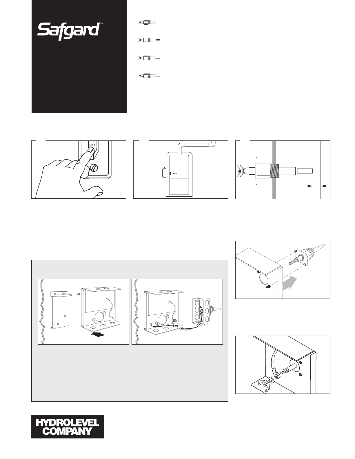
HOW TO INSTALL
1 2 3
SAFE
WATER
LINE
WARNING – To prevent electrical shock or
equipment damage, power must be off during
installation or servicing of the control. To prevent serious burns, the boiler should be thoroughly cooled before installing or servicing control. Only qualified personnel may install or service the control in accordance with local codes
and ordinances. Read instructions completely
before proceeding.
The probe may be installed in the boiler above
the lowest safe water level established by the
boiler manufacturer. Most manufacturers provide a suitable opening in the side of the boiler.
1/4"
Allow 1/4" clearance from the probe to any boiler
surface, tube or baffle. NOTE: Excessive use of
Teflon tape to seal probe piping threads may
insulate the control from boiler ground. This
could result in the control not operating.
4
R E M O T E M O U N T E D M O D E L S O N L Y
BA
A. To secure mounting plate to boiler jacket,* pre-drill two 3/32" pilot holes using the mounting plate as a template. Secure plate with sheet metal screws provided. Attach control to
mounting plate by slipping keyholes in back of chassis over pre-mounted screws on plate.
Tighten screws.
B. Using a wire nut, attach a wire (min 90°C) to the pigtail lead in the control box. Attach the
other end to the probe terminal in the remote probe housing. Attach a second wire between
the ground screw on the control chassis and one of the four screws in the remote probe
housing. Note: Wires and wire nuts not provided.
*Or other suitable surface
P.O. Box 1847
New Haven, CT 06508
Phone: (203) 776-0473
FAX: (203) 773-1019
Loosen the two control cover binding head
screws and remove the cover. Assemble the
chassis to the probe flange and secure with the
screws provided with the probe.
5
Connect the ring terminal wire lead to the probe
terminal stud and secure with the lock washer
and wing nut provided. With the power
removed, proceed with installation and wiring
according to the instructions on page 2. Upon
completion of wiring replace control cover.
Page 2
24VAC
HOT
COMMON
+
0
LIMIT
CONTROLS
AP2P112
BURNER
CIRCUIT
WATER
FEEDER
BURNER
POWER
SOURCE
24VAC
HOT
COMMON
BURNER
CIRCUIT
AP2P112
BURNER
POWER
SOURCE
BURNER
POWER
SOURCE
24
V
AC
+
0
LIMIT
CONTROLS
AP2P112
HOT
COMMON
BURNER
CIRCUIT
BURNER
POWER
SOURCE
24
V
AC
AP2P112
FACTORY
INSTALLED
JUMPER
COMMON
HOT
BURNER
POWER
SOURCE
24
V
AC
+
0
LIMIT
CONTROLS
AP2P112
BURNER
CIRCUIT
WATER
FEEDER
24VAC
AP2P112
REMOVE
JUMPER
24VAC
+
0
LIMIT
CONTROLS
AP2P112
BURNER
CIRCUIT
HOT
COMMON
BURNER
POWER
SOURCE
P2
2
1
AP2P112
AP2P112
WATER
FEEDER
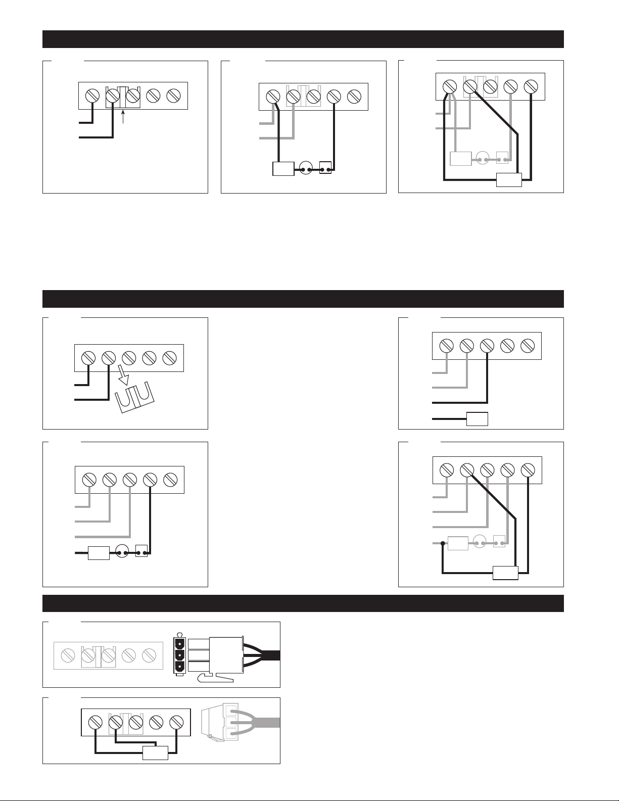
WIRING METHOD A: SAME POWER SOURCE FOR CONTROL AND BURNER CIRCUIT.
A1 A2
A1 Connect input voltage (24 VAC, 60 HZ) to
terminals 1 and 2. 24 VAC, 60 HZ must be supplied
to terminals 1 and 2 for internal operation of the
control.
WIRING METHOD B: SEPARATE POWER SOURCE FOR CONTROL AND BURNER CIRCUIT.
B1
B3
A2 Connect terminal 2 to burner circuit com-
mon. Connect terminal P2 to burner Circuit in
series with other limit controls. Consult boiler
manufacturer instructions for proper terminal connections. Control should be wired in series with
and before other limit controls.
䊴
B1Remove jumper between terminals 1
and P1. Connect input voltage (24 VAC, 60 HZ) to
terminals 1 and 2. 24 VAC 60 HZ must be supplied
to terminals 1 and 2 for internal operation of the
control.
Connect hot lead from the burner B2
control circuit to terminal P1. This terminal supplies power to terminal P2 in normal operating
conditions when water is at the probe. Connect
common to burner circuit. Note: Consult boiler
manufacturer instructions for proper terminal connections.
䊴
B3 Connect terminal P2 to burner circuit in
series with and before other limit controls.
Optional water feeder connection. B4
Connect feeder H to terminal 1. Connect feeder
“FEED” or “W” to terminal A. Connect terminal N to
common of the burner circuit supply. For feeders
with two leads, connect feeder hot to terminal A
and connect feeder common to common of the
burner circuit supply. Note: Use of solenoid valve
or McDonnell & Miller model 101A water feeder
may cause flooding and is not recommended for
use with this low water cut-off.
䊳䊳
䊳䊳
A3
A3 Optional water feeder connection. Connect
feeder N to terminal 2. Connect Feeder H to terminal 1. Connect feeder “FEED” or “W” to terminal A.
For water feeders with 2 leads, connect feeder
common to terminal 2 and feeder hot to terminal A.
Note: Use of a solenoid valve or McDonnell &
Miller Model 101A water feeder may cause flooding and is not recommended for use with this low
water cut-off.
B2
B4
WIRING METHOD C: PLUG CONNECTOR.
C1
C2
䊴
C1Plug wire harness connector into matching end on circuit board. IMPOR-
TANT: Factory installed jumper must be in place between
terminals 1 and P1.
䊴
C2 Optional water feeder connection. Connect feeder N to terminal 2.
Connect Feeder H to terminal 1. Connect feeder “FEED” or “W” to terminal A.
For water feeders with 2 leads, connect feeder common to terminal 2 and feeder hot
to terminal A. Note: Use of a solenoid valve or McDonnell & Miller Model 101A
water feeder may cause flooding and is not recommended for use with this low
water cut-off.
Page 3

CYCLEGARD
LOW-WATER
CUT-OFF
CYCLEGARD
LOW-WATER
CUT-OFF
Principle of Operation
P1
BURNER
POWER
P2
P1
BURNER
POWER
P2
Hydrolevel controls are electrically operated. A probe is installed in the boiler shell and connected to the control unit. Water is used as a conductor to
complete a circuit from the probe to the control unit. The control unit provides switching contacts to complete the burner control circuit and to operate an
optional alarm or water feeder.
NORMAL OPERATION
With water present at the probe, the control circuit is complete.
Contact between terminals P1 and P2 completes the burner circuit,
allowing for normal operation of the burner.
Operating Instructions
LOW WATER CONDITION
Whenever the water falls below the probe, a time delay is activated
in the control. After 15 seconds of a low water condition, the control
interrupts the burner circuit and shuts down the boiler. This time
delay feature prevents short cycling of the burner circuit during temporary low water levels common in turbulent steam boiler environments.
NOTE
For proper low water cut-off operation, the boiler should be cleaned at
initial installation and periodically thereafter. Refer to the boiler manufacturer’s instructions for cleaning procedures.
OPERATING TEST PROCEDURE
1. After installation, bring the boiler water to a safe operating level, turn
on power and set the thermostat to call for heat. The amber LED
lamp should be off. The boiler will fire after a 30 second delay.
2. Slowly
lower the boiler water to a point below the probe. The amber
LED lamp on the control will light. The lamp may begin to flicker
with the bouncing water level. Stop draining the boiler when the
lamp glows steadily. NOTE: The water should not be lowered
beyond a visible point in the gauge glass.
3. The boiler will shut down within 15 seconds.
IF BURNER DOES NOT SHUT DOWN IN LOW WATER
1. Check terminal block wiring to insure that all connections are
correct.
Maintenance
2. Check the probe installation to insure that there is 1/4" clearance
from any surface within the boiler or pipe. (Refer to Step 3 on page
1 of this instruction sheet.
3. Clean the boiler in accordance to the manufacturer’s instructions.
Machining oils, grease, rust and other contaminants in the boiler
water can cause foaming or surging and make a low water condition
difficult to detect during burner operation.
IF THE AMBER LED LAMP IS ON
The amber LED lamp indicates that the water is below the probe. If the
gauge glass shows that the water is at the correct operating level and
the amber LED is lit check the following:
1. Check for plugged gauge glass.
2. Make sure probe lead wire is properly secured to the terminal.
3. Check for proper ground between probe and boiler shell. Excessive
use of Teflon tape or sealing compound may isolate the probe from
the boiler shell.
4. Remove probe and examine for oily residue. Clean probe with steel
wool and skim boiler.
To ensure optimum performance remove and inspect probe annually. Clean any sediment or scale from the probe using a scouring pad or steel
wool. Re-install the probe and perform the Operating Test Procedure described above.
Page 4

2"
SQUARE
17/8"
313/16"
15
/16"
1"
3
/4" NPT
5
/16"
2"
SQUARE
17/8"
49/16"
1"
3
/4" NPT
5
/16"
111/16"
225/32
37/8
15/8
11/8
15/8
23/8
BOTTOM
59/16
51/2
1.00
BACK
11/8
23/8
15/8
TOP
VXT WATER FEEDER
PROBES
Test Pressure: 1000 PSI, All Models
EL1214 – STANDARD MODEL – 3/4" NPT
For 1/2”, order Model No. EL-1220
The VXT Water Feeder (available separately) can be installed with Hydrolevel or
other low water cut-offs to automatically
replenish boiler water in the event of a low
water condition. The VXT offers programmable
feed amount
and
feed delay
settings. These can easily be set to ensure
the proper feed amount and to provide
adequate time for condensate to return to
EL1214-P – 3/4" NPT
the boiler before starting a feed cycle. The
VXT Feederʼs
Digital Feed Counter
tracks
the amount of water added to the boiler
exposing system leaks, which can significantly shorten the life of a cast iron boiler.
Additional features including a manual feed
button, underfeed and flood protection
make the VXT an ideal choice for safety
and convenience.
EL1214-R
REMOTE PROBE
THE PROBE MAKES THE DIFFERENCE
The probe used in all Hydrolevel controls offers
you distinctive advantages. Unlike float devices,
there are no moving parts to wear stick, or
“hang-up” the in harsh boiler environment .
LIMITED MANUFACTURERʼS WARRANTY
We wa rran t pr oduc ts manu f act u red b y
Hydrolevel Company to be free from defects in
material and workmanship for a period of two
years from the date of manufacture or one year
from the date of installation, whichever occurs
first. In the event of any claim under this warranty or otherwise with respect to our products
which is made within such period, we will, at our
option, repair or replace such products or refund
the purchase price paid to us by you for such
products. In no event shall Hydrolevel Company
A stuck or “hung-up” float can cause dangerous
low water conditions. And if suddenly released, a
float can feed cold water into overheated tubes
or plates and cause explosive results.
be liable for any other loss or damage, whether
direct, indirect, incidental or consequential. This
warranty is your EXCLUSIVE remedy and shall be
IN PLACE OF any other warranty or guarantee,
express or implied, including, without limitation,
any warranty of MERCHANTABILITY or fitness
for a particular purpose. This warranty may not
be assigned or transferred and any unauthorized
transfer or assignment thereof shall be void and
of no force or effect.
The Hydrolevel control has no float bowl so sediment cannot collect. The reliable solid state circuitry and low maintenance probe are designed
to provide years of troublefree operation.
MAXIMUM PRESSURE: 15 PSI
INPUT VOLTAGE: 24 VAC, 60 HZ
SWITCH CONTACTS: SPDT
SWITCH RATINGS
AND ALARM CIRCUIT: 50 VA @ 24 VAC
Pilot Duty
P.O. Box 1847
New Haven, CT 06508
Phone: (203) 776-0473
FAX: (203) 773-1019
 Loading...