

Page 1
MODEL 3100
Combination Low Water
Cut-Off & Universal
Temperature Limit Control
for Gas Boilers
PATENTS PENDING
• Dual Function Design – HydroStat performs both high temperature limit and low
water cut-off functions when installed with a Hydrolevel Electro-Well™.
Replaces Common Aquastat
•
wells to replace both cold-start and triple-action Aquastats
*
odels – Can be installed on existing immersion
M
®
. Industry standard
wiring designations make change-outs quick and easy.
• Digital Display – Easy to read LED continually displays boiler temperature. Also
isplays temperature limit and differential settings during adjustment.
d
• Easy to Set – Dials for setting temperature limits and differentials eliminate
complicated programming.
Advanced Micro-Controller Design – Utilizes dual thermistor technology for
•
better accuracy, response and reliability.
*Aquastat is a registered trademark of Honeywell International, Inc.
•
Electrical shock hazard. To prevent electrical shock, death or
WARNING
installing or servicing control. Only qualified personnel may install or service this control in
accordance with local codes and ordinances. Read instructions completely before proceeding.
quipment damage, disconnect power supply before
e
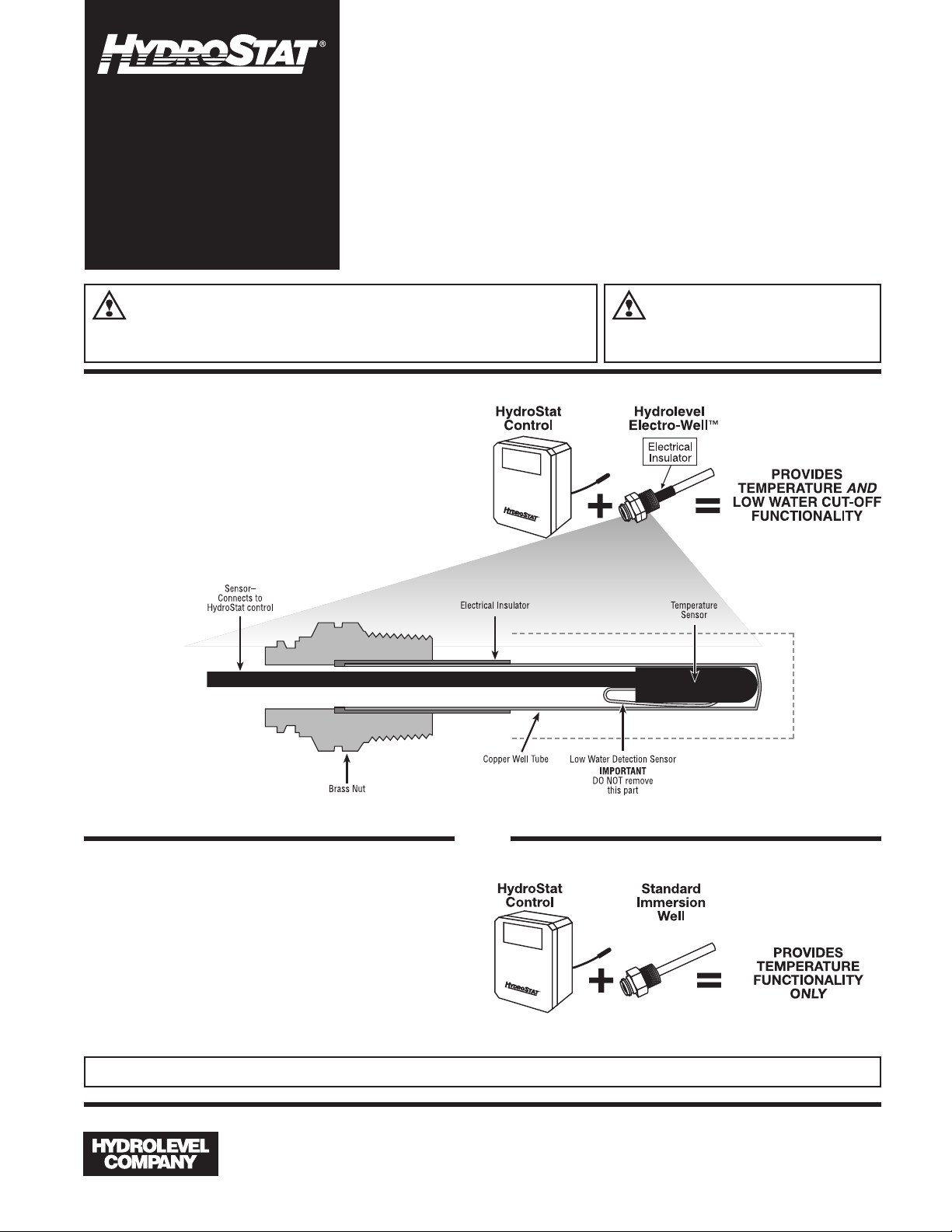
HydroStat installed
with Electro-Well™
When installed with the Hydrolevel Electro-Well,
HydroStat will provide
cut-off functionality. If the control was supplied by the
boiler manufacturer, it was installed with an ElectroWell. The Electro-Well is available separately for field
installations. See Electro-Well models on page 8.
both
temperature and low water
/2" CLEARANCE
1
/2" CLEARANCE
1
To prevent serious
CAUTION
should be thoroughly cooled before installing or
servicing control.
urns, boiler
b
IIMMPPOORRTTAANNTT::
For proper operation of the low
water cut-off function, there must
be a minimum of
½" clearance
between the cop-
1/2" CLEARANCE
per well tube and
any surface within
the boiler.
OR
HydroStat installed with
a standard immersion well
For field replacement of common Aquastat®models,
HydroStat can be installed with the immersion well
already on the boiler. In this configuration, HydroStat
will provide the temperature functionality of the control
being replaced, but will not provide low water cut-off
functionality. The “LWCO Active” LED will not illuminate.
IMPORTANT When installed on a standard immersion well, HydroStat will not provide low water cut-off functionality.
83 Water Street • New Haven, CT 06511 • Phone (203) 776-0473 • FAX (203) 773-1019 • www.hydrolevel.com
1
Page 2
MOUNTING THE CONTROL
IMPORTANT Make sure that the immersion well or Electro-Well™ is installed on the boiler manufacturerʼs
designated temperature limit control tapping. Note: If installing an Electro-Well, pipe sealing compound should be
used. Teflon tape is not recommended.
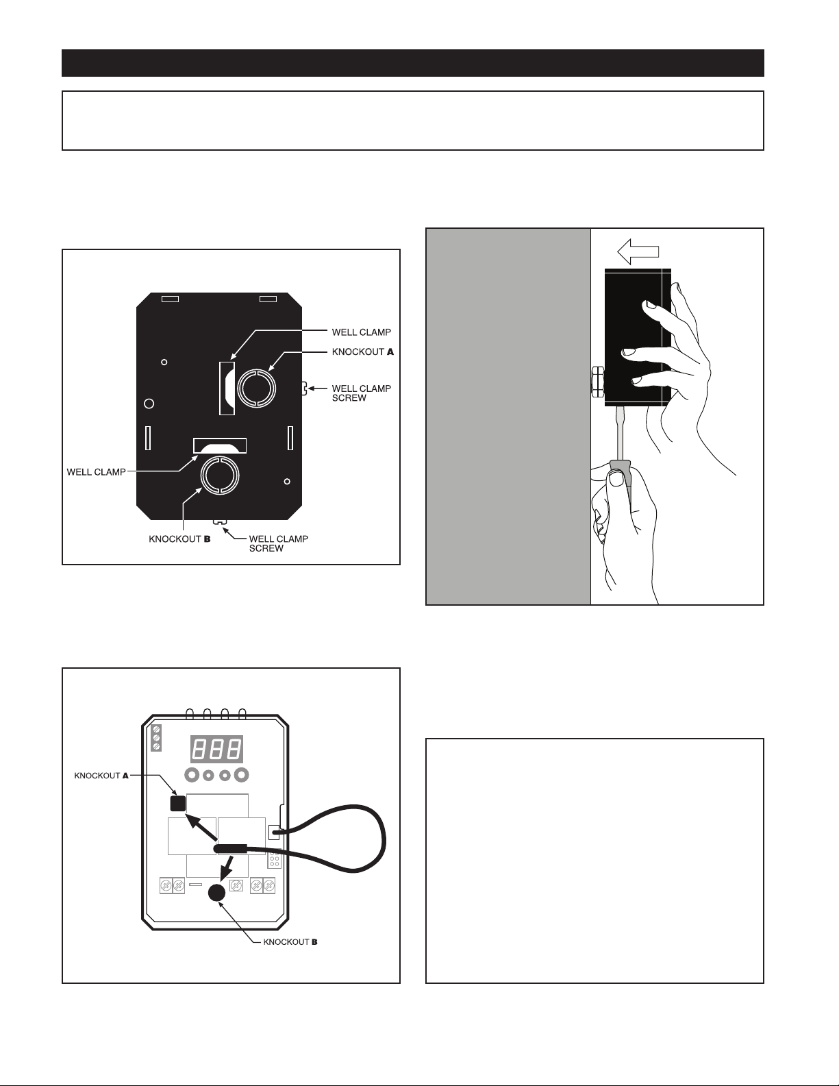
STEP 1
back of the control (Fig. 1). Select which of the two positions
(2 knockouts) is best for the location of the control. Remove
he knockout.
t
FIG. 1
Two mounting positions are available on the
BACK OF HYDROSTAT BOX
STEP 2 Place control on the well. While holding box
against well nut, tighten well clamp screw. (Fig. 2)
STEP 3 Insert sensor ALL THE WAY into well through
the knockout (A or B) you have chosen. (Fig. 3)
FIG. 3
FIG. 2
NOTE: In the case of space restrictions, the HydroStat control may be mounted in a horizontal orientation without any
loss of function. Hydrolevel recommends vertical mounting,
when possible, for proper orientation of LED display.
REMOTE MOUNTING
The following kits are available separately for mounting
the HydroStat control box in a remote location. Each kit
includes mounting hardware and a remote sensor.
Part No. Description
48-101 Wall/Jacket Mounting Kit with 2' sensor cord
48-102 Wall/Jacket Mounting Kit with 4' sensor cord
48-103 Wall/Jacket Mounting Kit with 10' sensor cord
48-104 Wall/Jacket Mounting Kit with 20' sensor cord
48-121 Pipe Mounting Kit with 4' sensor cord
2
Page 3
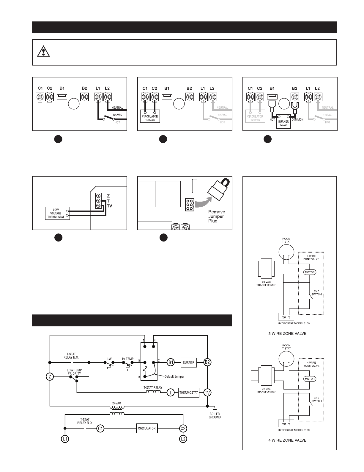
WIRING
WARNING
STEP 1
to terminal L1. Connect 120 VAC
Neutral to terminal L2. Disconnect
means and overload protection as
required (provided by others).
Connect 120 VAC Hot
Electrical shock hazard. To prevent electrical shock, death or equipment damage, disconnect power supply before
installing or servicing this control.
STEP 4 Connect wires from Low
Voltage Thermostat to T and TV.
STEP 2 Connect the circulator to
C1 and C2 (C2 is neutral).
STEP 5 If the boiler is equipped
with a plug-in style vent damper,
unplug the factory installed jumper
from the receptacle on the circuit board
and replace it with the vent damper
plug. NOTE: Once a vent damper plug
is connected to the HydroStat, the control is permanently altered and will no
longer function when the vent damper
plug is disconnected.
STEP 3 Connect wire from 24
VAC Burner Circuit to B1(quick connect). Connect wire from 24 VAC
Burner Circuit common to B2 (fork).
ZONE VALVE WIRING
MPORTANT: Use a separate transformer to
I
power zone valves. Connecting zone valves to
Z-TV may overload the HydroStat and cause a
lock-out condition (see
for more information). The total load, including the
burner circuit, vent damper, and Z-TV connections
must not exceed 1.2 amps (30 VA). Connect zone
valve end-switch to T-TV as shown below.
Troubleshooting
on page 6
SCHEMATIC/LADDER DIAGRAM
3
Page 4

SETTING THE CONTROL
WARM START
(maintains temperature for domestic hot water)
Low Limit Switch = ON
COLD START
Low Limit Switch = OFF
Example
High Limit = 180°
Differential = 10°
On a call for heat, the burner will
shut off at 180° and restart at
170° (180°-10°). The circulator
will run as long as there is a call
for heat.
High Temperature Limit
(Adjustable 100° to 220°F)
De-energizes burner at HIGH
LIMIT setting
High Temperature Limit
(Adjustable 100° to 220°F)
De-energizes burner at HIGH
LIMIT setting
High Temperature
Differential
(Adjustable 10° to 30°F)
Re-energizes burner when
temperature falls to the HIGH
LIMIT DIFFERENTIAL set point
High Temperature
Differential
(Adjustable 10° to 30°F)
Re-energizes burner when
temperature falls to the HIGH
LIMIT DIFFERENTIAL set point
Low Temperature Limit
(Adjustable 110° to 200°F)
De-energizes burner at LOW
LIMIT setting
Low Temperature
Differential
(Adjustable 10° to 30°F)
Re-energizes burner when
temperature falls to the LOW
LIMIT DIFFERENTIAL set point
Example
High Limit = 180°
Differential = 10°
On a call for heat, the burner will
shut off at 180° and restart at
170° (180°-10°). The circulator
will run as long as there is a call
for heat.
Example
Low Limit = 150°
Differential = 10°
When there is no call for heat,
the burner fires at 140°
(150°-10°) to maintain boiler
temperature. Burner shuts off
at 150°.
NOTE: To prioritize domestic hot
water the HydroStat control will
not allow the c irculator to
operate at any time the
temperature is below the low
limit setting.
Dynamic
Display
ater Temperature
W
and Real Time
Verification of
etting Adjustments.
S
All Settings are
Displayed Every
ime Control is
T
Powered Up
Low Temperature
Limit Setting
OFF or 110°-200°F)
(
actory OFF
F
ow Temperature
L
Differential Setting
(10°-30°F)
Factory 10°F
iagnostic LEDs
D
High Temperature
Limit Setting
100°-220°F)
(
actory 190°F
F
igh Temperature
H
Differential Setting
(10°-30°F)
Factory 10°F
NOTE: Be careful not to select overlapping temperature settings.
For example: If the HIGH TEMPERATURE LIMIT is set at
190°F with a HIGH TEMPERATURE DIFFERENTIAL set at 20°F,
then the LOW TEMPERATURE LIMIT needs to be set at 170°F
(190°F - 20°F = 170°F) or below.
IMPORTANT: To prevent flue gas condensation and reduce fatigue
caused by thermal cycling on conventional (non-condensing) boilers,
both HIGH and LOW LIMIT set points should be 150°F or above
(Limit Setting - Differential Setting ≥ 150°F). Boiler manufacturerʼs
temperature requirements supercede these recommendations.
To set COLD START operation
Operates on call for heat only.
Low Temperature Limit
Make sure Low Temperature Limit is turned fully counterclockwise (OFF position).
Low Temperature Differential
No change is required.
High Temperature Limit
factory setting = 190°F)
(
Adjust setting until desired temperature is displayed.
High Temperature Differential
factory setting = 10°F)
(
Using a small screwdriver, adjust setting until desired differential is displayed.
To set WARM START operation
Maintains temperature for domestic hot water.
Low Temperature Limit
Adjust setting until desired temperature is displayed.
Low Temperature Differential
Using a small screwdriver, adjust setting until desired differential is displayed.
High Temperature Limit
(factory setting = 190°F)
Adjust setting until desired temperature is displayed.
High Temperature Differential
(factory setting = 10°F)
Using a small screwdriver, adjust setting until desired differential is displayed.
OPERATION
4
Page 5

LED LEGEND
remain lit until the water temperature
falls below the high limit setting less
the differential setting. The HydroStat
control will prevent burner operation
while this LED is on.
NOTE: This LED illuminates regularly
during normal boiler operation.
LWCO ACTIVE Indicates that
the low water cut-off (LWCO) function
TEMP ACTIVE Indicates that
he HydroStat control is powered and
t
that the temperature function is active.
TEMP HIGH TEMP Illuminates
when the boiler water temperature
reaches the high limit setting. It will
of the HydroStat control is active.
When the control is installed with a
ydrolevel Electro-Well, this LED will
H
be on at all times when the control is
powered.
NOTE: If the control was installed with
a well other than the Electro-Well, this
TROUBLESHOOTING
Burner Will Not Fire See Flow Chart 1, page 6
Burner Will Not Shut Down See Flow Chart 2, page 7
Temperature Display Exceeds
High Limit Setting
Under normal operation, boiler temperature will continue to rise after the control shuts off
the burner. This condition, known as “thermal stacking”, results from hot boiler surfaces
continuing to release heat into the boiler water.
LED will not illuminate. This indicates
that the control is providing
temperature function only.
LWCO LOW WATER Indicates
that the boiler is in a low water
condition. The HydroStat control will
revent burner operation during this
p
condition.
IMPORTANT:
The system must be checked by a
qualified heating professional prior to
esuming operation.
r
WARNING: ALLOW THE BOILER TO
FULLY COOL BEFORE ADDING
WATER.
Red Light on Circuit Board
is Flashing
No Domestic Hot Water
Boiler Will Not Maintain
Low Limit Temperature
Temperature Display
Differs from Boiler
T&P Gauge Temperature
Reading
LWCO “Active” Light
(Green LED) Is Not On
Low Water Light
(Red LED) Is On
The red light to the left of the temperature display will flash if the transformer has been
overloaded. (See top portion of troubleshooting flow chart on page 6.)
If the boiler is equipped with a tankless coil, make sure the low limit setting on the
HydroStat is set properly. NOTE: If the low limit setting is dialed fully counter clockwise, it
will shut off the low temperature maintenance feature.
Check for overlapping high temperature setting. If the high limit setting is set below the
low limit setting, the control will default to the high limit setting and the corresponding
high limit differential setting.
Temperature variances can result from differing water temperatures within the boiler or
different reaction times of the two devices. If the HydroStat temperature is significantly
below the T&P gauge temperature, make sure the thermistor is inserted all the way to
the end of the well. If installed in an existing conventional well, check that hardened heat
conducting grease has not impeded the insertion of the thermistor. Clean or replace the
well to ensure proper insertion of the sensor.
When Installed on Standard Immersion Well: This is a normal condition. The control
will provide temperature functionality only. The HydroStat must be installed on a
Hydrolevel Electro-Well for low water cut-off functionality.
When Installed on a Hydrolevel Electro-Well: The control is detecting unusually high
conductivity. Check for minimum ½" clearance between the copper well tube and any
surface within the boiler.
WARNING: A low water condition is a serious and potentially dangerous condition. Do
not attempt to add water to a hot boiler. Allow the boiler to fully cool before adding water.
1. If the heating system is filled with water, pull the sensor out of the well and inspect it.
Make sure that the metal clip on the sensor is intact. This metal clip must be in contact
with the inside of the copper well in order for the control to sense the presence of
water. Check that the well does not have excessive build-up of heat transfer grease
that may interfere with clip contacting the well.
2. Remove well and examine for excessive residue build-up. Clean and re-install.
5
Page 6

Troubleshooting Flow Chart 1 – Burner Will Not Fire
The burner will not fire until overload condition is corrected.
Is the
Red LED on
the Circuit Board
lashing?
f
NO
YES
The Load on
he Transformer
t
Exceeds 30 VA.
Recheck wiring – Terminal TV is electrically connected to boiler
ground. If wiring to TV & Z is reversed, there could be a short
across the transformer.
Make sure that the total load, including the burner circuit, vent
damper and Z & TV connections does not exceed 30 VA.
Is the
reen LED
G
(TEMP ACTIVE)
On?
YES
Is the
Red LED
On?
NO
Is the
Yellow LED
On?
N
O
Is the
Thermostat
(T-TV) Calling
for Heat?
YES
NO
YES
YES
NO
The Control is
Not Powered.
The Control is
Sensing
Low Water.
The Control is
Sensing High
Temperature.
Is the
Low Limit Dial
Set to OFF?
NO
he Temp Active LED will be on at all times when the control is
T
powered.
Check for 120 VAC on terminals L1 and L2.
CAUTION – ALWAYS ALLOW A BOILER TO COOL BEFORE ADDING WATER
The burner will not fire until the low water condition is satisfied.
Check that the system is filled with water.
Check that the sensor is inserted correctly into well.
Note: The use of heat-conductive grease may interfere with the
contact between the spring clip and the copper well tube.
Check that the control is tightly clamped to the well.
The burner will not fire until the boiler water has dropped to the
high limit differential set-point. See HydroStat Settings chart.
Check that the high temperature setting is correct.
When the low temperature
setting is set to OFF, the
HydroStat will act as a cold
YES
start control. The burner will
not fire unless there is a call
from the thermostat (T-TV).
Set thermostat to call for
heat. Burner should fire.
If the boiler has a tank-
less coil, set the Low
Temperature Limit to
maintain temperature.
Is There
24 VAC
Between B1
and B2?
NO
Replace
Control
YES
The Control
is Operating
Properly.
HydroStat is supplying 24 VAC to the burner circuit.
Recheck wiring and operation of burner and other limit controls.
If both the red and yellow LEDs are off and
there is a call to fire the burner, there will be
24 VAC on terminals B1 and B2.
If 24 VAC is not present, the control should
be replaced.
6
Page 7

Troubleshooting Flow Chart 2 – Burner Will Not Shut Down
s the
I
Red LED
n?
O
NO
Is the
Yellow LED
On?
NO
Is the
hermostat
T
(T-TV) Calling
for Heat?
NO
Is the
Low Limit Dial
Set to OFF?
YES
YES
Y
N
he Control is
T
Sensing
ow Water.
L
The Control is
Sensing High
Temperature.
The Control is
ES
Operating
Normally.
Check temperature display. When the Low Limit is
O
set, the HydroStat will fire the burner until the
temperature reaches the Low Limit Setting.
WARNING!
URN OFF POWER TO BURNER IMMEDIATELY!
T
CAUTION – ALWAYS ALLOW A BOILER TO FULLY COOL
BEFORE ADDING WATER.
Recheck wiring. Make sure that burner is wired to
1. Burner should never fire when red or yellow
B
LED is lit.
The burner will continue to fire when there is a call
from the thermostat.
YES
Is there
24 VAC between
B1 and B2?
YES
Replace
Control.
NO
Recheck
Wiring.
When there is no call to fire the burner, the voltage
should be 0 volts between B1 and B2.
Make sure the burner is wired to B1.
If there is no call for heat (from T-TV or Low Limit),
there should be 0 VAC between B1-B2.
If there is voltage between B1-B2, the control
should be replaced.
7
Page 8

LOW WATER CUT-OFF TEST PROCEDURE
HydroStatʼs low water cut-off function is active when the control is installed on a Hydrolevel Electro-Well. To test the low water
cut-off function:
to simulate a low water condition.
should not fire.
ACTIVE light should illuminate and the burner should
NOTE: Do not remove the sensor from the well while the control is powered.
Turn OFF power to the control.Set the thermostat to call for heat.Gently slide the sensor out of the well
Turn ON power to the control. The red LOW WATER light should come on and the burner
Turn OFF power again and reinstall the sensor in the well.Turn ON power to the control. The green LWCO
fire.
MAINTENANCE
Remove the Electro-Well from the heating system every five years and clean any scale or sediment deposits from all parts that
are exposed to the boiler water. After cleaning, reinstall the well using pipe sealing compound. Teflon tape is not recommended.
ELECTRO-WELLS
DIMENSIONS
SPECIFICATIONS
Input voltage 120 VAC, 60 HZ
Burner contacts 30 VA@24 VAC
Circulator contacts 5.8 FLA, 34.8 LRA@120 VAC
Operating range – low limit Off or 110°F - 200°F
Operating range – high limit 100°F - 220°F
Operating range – differential 10°F - 30°F
HYDROSTAT MODEL 3100
LIMITED MANUFACTURERʼS WARRANTY
We warrant products manufactured by Hydrolevel Company to be free from defects in
material and workmanship for a period of two years from the date of manufacture or
one year from the date of installation, whichever occurs first. In the event of any claim
under this warranty or otherwise with respect to our products which is made within
such period, we will, at our option, repair or replace such products or refund the purchase price paid to us by you for such products. In no event shall Hydrolevel Company
83 Water Street • New Haven, CT 06511 • Phone (203) 776-0473 • FAX (203) 773-1019 • www.hydrolevel.com
be liable for any other loss or damage, whether direct, indirect, incidental or consequential. This warranty is your EXCLUSIVE remedy and shall be IN PLACE OF any other
warranty or guarantee, express or implied, including, without limitation, any warranty
of MERCHANTABILITY or fitness for a particular purpose. This warranty may not be
assigned or transferred and any unauthorized transfer or assignment thereof shall be
void and of no force or effect.
8
 Loading...