

Page 1
No moving parts to stick, wear or hang-up.
250 Series
Pump Control Low Water
Cut-Off Combination
120 VAC Operating Voltage
Max. Pressure 250 psi
LISTED
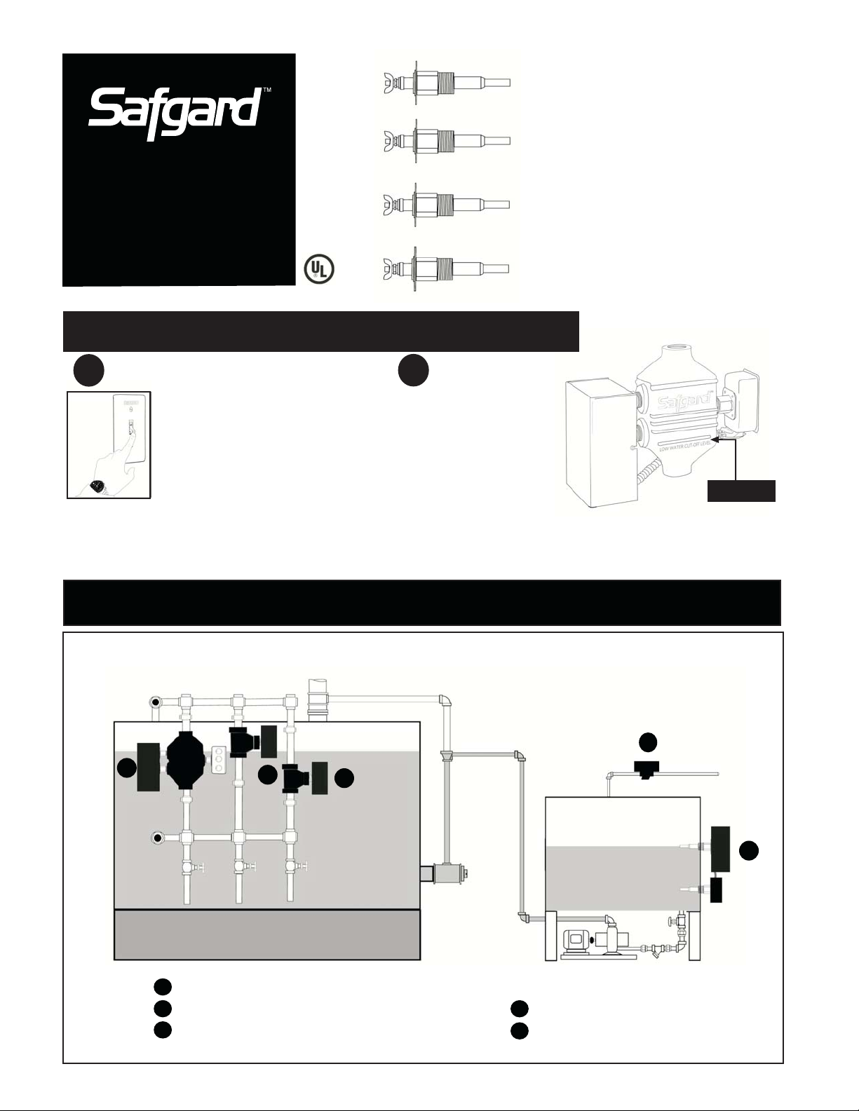
HOW TO INSTALL
WARNING!
1
WARNING: To prevent electrical shock
and equipment damage, power must
be off during installation or servicing of
the control. To prevent serious burns
the boiler should be thoroughly cooled
before installing or servicing control.
Only qualified personnel may install or service the control
in accordance with local codes and ordinances.
Read instructions completely before proceeding.
No replacement or rebuilding of floats or
mechanical parts.
Reliable Electronic Design
Made in the U.S.A
LOCATION
2
Install the Safgard 250 in a
1" equalizing line equipped
with a blow-down valve
meeting applicable state
and local codes. The control
should be located so that
the "LOW WATER CUT-OFF LEVEL marked on the control casting
is at least 1/2 above the lowest permissible water level as specified
by the boiler manufacturer.
LOW WATER CUT-OFF
LEVEL INDICATOR
TYPICAL APPLICATIONS
1
Safgard 250 Pump Controller LWCO Combination
1
Safgard 270 High Water Limit/Alarm
2
3
Safgard 550 or 750 as Secondary LWCO
2
3
Safgard VF-120 Solenoid Valve
4
5
Safgard 727 Tank Control
4
INCOMING WATER LINE
5
Page 2
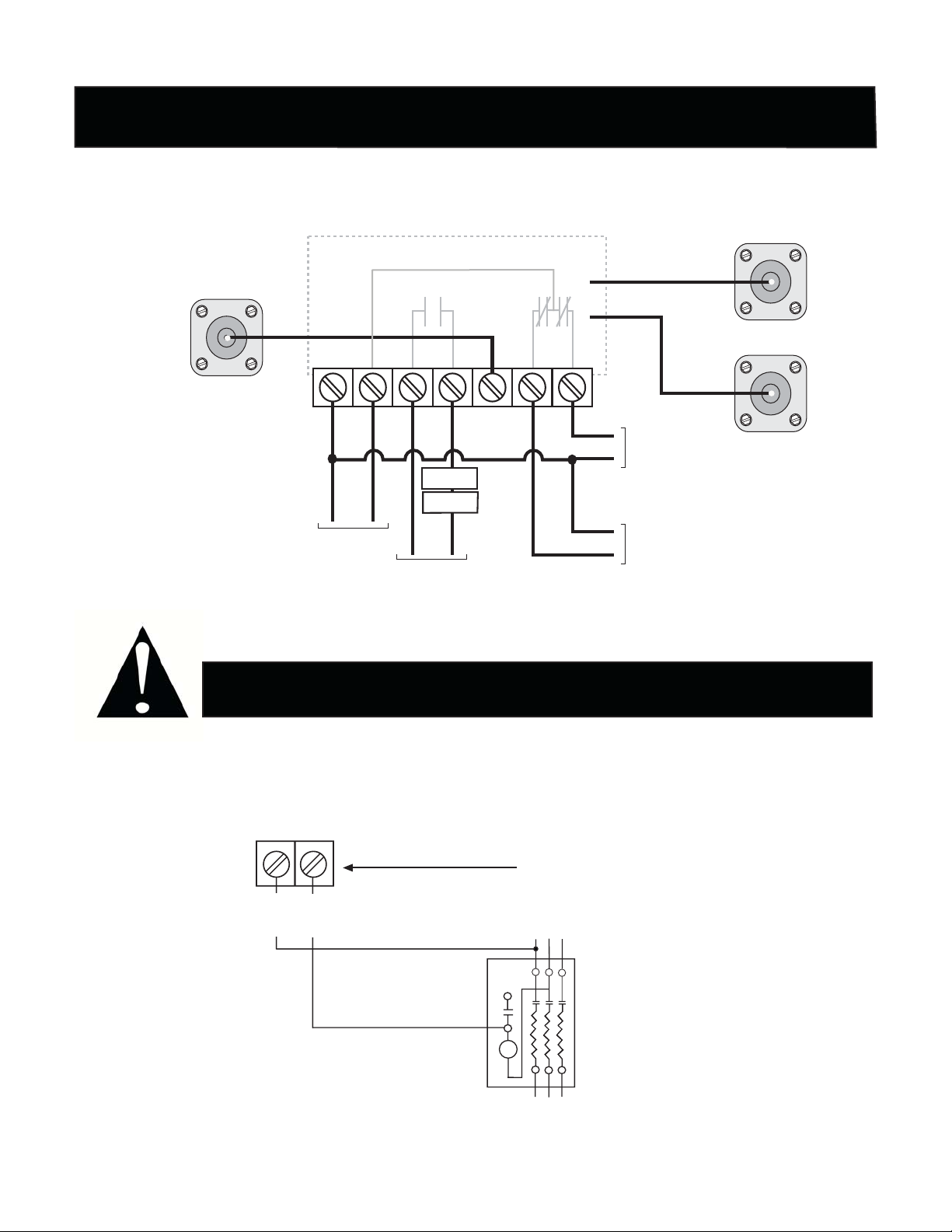
WIRING
HOTHOT
COMMONCOMMON
HOTHOT
NEUTRALNEUTRAL
H H
PP
PPPFEFEFEAA
VV
MODEL 250 Low Water Cut-Off and Pump Control
ALL WIRING SHALL
BE NEC CLASS I
OPEN CIRCUIT
VOLTAGE TO PROBE
140 VAC
FEED
PROBE
(FEED ON)
MAXIMUM PRESSURE: 250 PSI
INTERNAL WIRING
GGG
NEUTRAL
H
HOT
120 VAC 60 HZ
INCOMING
POWER
P
LIMIT
BURNER
HOT
COMMON
BURNER POWER
SOURCE
5.8 FLA 34.8 LRA
BLUE
WHITE
UPPER PROBE
(FEED OFF)
A
V
TO FEED
PUMP CONTROL
CIRCUIT
125 VA PILOT DUTY
TO ALARM CIRCUIT
120 VA, 60 HZ, 10A
LOWER
PROBE
(LWCO)
The Safgard 250 requires connection to a 120VAC power source to enable the control to operate.
IMPORTANT!
The Safgard 250 is intended as a pilot control only and must be installed with a relay
between it and both the condensate pump and burner circuit. Direct wiring of the control
to either the burner circuit or condensate pump can result in failure of the control.
250 PUMP TERMINALS
A
V
LINE
TYPICAL PUMP STARTER WIRING. SEE RELAY MANUFACTURERS
INSTRUCTIONS FOR MORE COMPLETE INFORMATION.
Page 3
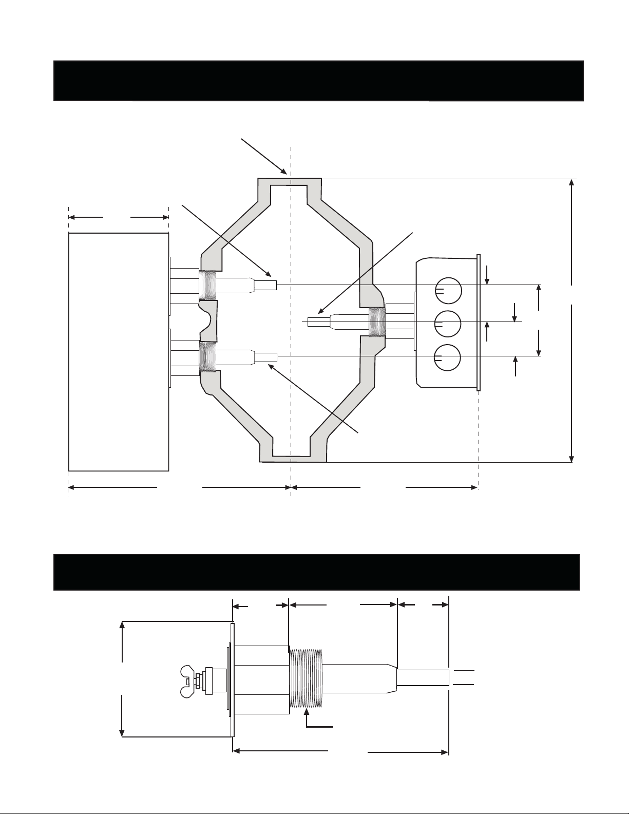
DIMENSIONAL DATA
1 NPT (BOTH ENDS)
PUMP OFF
1/4
3
PUMP ON
1
1/16
1
3/16
1/2
8
1/4
2
7 MAX
PROBE DATA
2
SQUARE
LOW WATER CUT-OFF
6 MAX
Maximum Steam Pressure 250 PSI
15/16
7/8
1
3/4 NPT
1
5/16
13/16
3
Probe Test Pressure 1000 PSI
Page 4

BLOW-DOWN & TEST PROCEDURE
CAUTION!- Blow down valve should be piped to a proper drain connection to avoid exposure to
steam discharge. Severe injury could result from failure to follow these instructions.
Blow down the 250 Series control when the water level is at its normal operating level (between middle and upper
probe) - with the the burner on.
Slowly open the column blow-down valve. The water level should begin to drop in the site glass. When water falls below
the middle probe, the pump or valve should energize. Continue draining the blow down column until water has fallen
below the bottom probe. Boiler should shut down immediately. Close the blow-down valve. Water should begin to rise
in the site glass. The burner should refire after covering the bottom probe and water should continue to rise in the site
glass. When water reaches the top probe the burner should continue to fire and the pump or valve should de-energize.
If the control fails to react as described above recheck wiring and/or probes for sludge or sediment buildup.
MAINTENANCE
In addition to the blow-down and test procedure above, the probes should be removed and examined annually. The
probes can usually be cleaned with a soft cloth although they are rugged enough to be cleaned with steel wool or a
scouring pad if a more crystaline or solid buildup is present. Probes should be inspected and cleaned more often on
systems with high make-up water or untreated boiler water.
MANUAL RESET FEATURE (Model 250M)
The Safgard 250M manual reset incorporates a 90-second time delay that prevents nuisance lockouts. During
temporary low water conditions such as column blow-down, excessive surge or slow condensate return, the burner
will shut down immediately but will not lock out for 90 seconds. The burner will restart automatically if the water
returns to a safe level within 90 seconds. The manual reset does not require resetting after a power failure.
Likewise, power interruptions will not reset the manual reset once engaged. With the Safgard manual reset design,
a genuine low water condition must be detected before reset is actuated and the only procedure for resetting a
tripped reset involves operator contact.
LIMITED MANUFACTURERS WARRANTY
We warrant products manufactured by
Hydrolevel Company to be free from defects
in material and workmanship for a period of
two years from the date of manufacture or
one year from the date of installation,
whichever occurs first. In the event of any
claim under this warranty or otherwise with
respect to our products which is made within
such period, we will, at our option, repair or
replace such products or refund the purchase
price paid to us by you for such products
FRONT
Top of Control
SLIDE MANUAL RESET TOWARD FRONT OF CONTROL TO RESET
In no event shall Hydrolevel Company be liable
for any other loss or damage, whether direct,
indirect, incidental or consequential. This
warranty is your EXCLUSIVE remedy and shall
be IN PLACE OF any other warranty or
guarantee, express or implied, including, without
limitation, any warranty of MERCHANTIBILITY
or fitness for a particular purpose. This warranty
may not be assigned or transferred and any
unauthorized transfer or assignment thereof
shall be void and of no force or effect.
.
MANUAL
RESET
BUTTON
.
P.O. Box 1847
New Haven, CT 06508
Phone: (203) 776-0473
Fax: (203) 773-1019
www.hydrolevel.com
Page 5

No moving parts to stick, wear or hang-up.
250WC Series
Pump Control Low Water
Cut-Off Combination
120 VAC Operating Voltage
Max. Pressure 250 psi
LISTED
HOW TO INSTALL
WARNING!
1
To prevent electrical shock and
equipment damage, power must be off
during installation, inspection or servicing
of the control.
To prevent serious burns the boiler
should be thoroughly cooled before
installing or servicing control.
Only qualified personnel may install or service the control
in accordance with local codes and ordinances. Read
instructions completely before proceeding.
No replacement or rebuilding of floats or
mechanical parts.
Reliable electronic design.
Made in the U.S.A.
LOCATION
2
Install the Safgard 250WC
in a 1" equalizing line
equipped with a blow-down
valve meeting applicable
state and local codes. The
control should be located
so that the "LOW WATER CUT-OFF LEVEL marked on the control
casting is at least 1/2 above the lowest permissible water level as
specified by the boiler manufacturer.
LOW WATER CUT-OFF
LEVEL INDICATOR
TYPICAL APPLICATIONS
1
2
Safgard 250 Pump Controller LWCO Combination
1
Safgard 270 High Water Alarm
2
3
Safgard 550 or 750 as Secondary LWCO
3
Safgard VF-120 Solenoid Valve
4
5
Safgard 727 Tank Control
4
Incoming Water Line
5
Page 6

WIRING
HOTHOT
COMMONCOMMON
HOTHOT
NEUTRALNEUTRAL
H H
PP
PPPFEFEFEAAAVV
MODEL 250WC Low Water Cut-Off and Pump Control
MAXIMUM PRESSURE: 250 PSI
INTERNAL WIRING
BLUE
WHITE
FEED
PROBE
(FEED ON)
ALL WIRING SHALL
BE NEC CLASS I
OPEN CIRCUIT
VOLTAGE TO PROBE
140 VAC
GGG
NEUTRAL
120 VAC 60 HZ
INCOMING
POWER
H
HOT
P
LIMIT
BURNER
HOT
COMMON
BURNER POWER
SOURCE
5.8 FLA 34.8 LRA
V
TO FEED
PUMP CONTROL
CIRCUIT
125 VA PILOT DUTY
TO ALARM CIRCUIT
120 VA, 60 HZ, 10A
UPPER PROBE
(FEED OFF)
LOWER
PROBE
(LWCO)
The Safgard 250WC requires connection to a 120VAC power source to enable the control to operate.
IMPORTANT!
The Safgard 250WC is intended as a pilot control only and must be installed with a relay
between it and both the condensate pump and burner circuit. Direct wiring of the control
to either the burner circuit or condensate pump can result in failure of the control.
250WC PUMP TERMINALS
A
V
LINE
TYPICAL PUMP STARTER WIRING. SEE RELAY MANUFACTURERS
INSTRUCTIONS FOR MORE COMPLETE INFORMATION.
Page 7

DIMENSIONAL DATA
UPPER PROBE
(PUMP OFF)
LOW WATER CUT-OFF PROBE
7/8”
10
1/8”
8
3/8”
7
3/4”
5
LOW
WATER
LEVEL
1” NPT
(TYP. BOTH ENDS)
1/2” NPT
(TYP 2 PLACES)
FOR SIGHT GLASS
(NOT SUPPLIED)
1/2”
9
15/16”
6
15
3/4”
1/2” NPT
TYP. 3 PLACES
ON FAR SIDE
FOR TRI-COCKS
PROBE DATA
2”
SQUARE
7/8”
3
1/8”
3
6”
MAX
6”
MAX
LOWER PROBE
250 PSI Steam Pressure
7/8
15/16”
1 ”
1”
(PUMP ON)
5/16”
3/4” NPT
13/16
3 ”
Probe Test Pressure 1000 PSI
Page 8

BLOW-DOWN & TEST PROCEDURE
CAUTION!- Blow down valve should be piped to a proper drain connection to avoid exposure to
steam discharge. Severe injury could result from failure to follow these instructions.
Blow down the 250WC Series control when the water level is at its normal operating level (between middle and upper
probe) - with the the burner on.
Slowly open the column blow-down valve. The water level should begin to drop in the site glass. When water falls
below the middle probe, the pump or valve should energize. Continue draining the blow down column until water has
fallen below the bottom probe. Boiler should shut down immediately. Close the blow-down valve. Water should begin
to rise in the site glass. The burner should refire after covering the bottom probe and water should continue to rise in
the site glass. When water reaches the top probe the burner should continue to fire and the pump or valve should deenergize. If the control fails to react as described above recheck wiring and/or probes for sludge or sediment buildup.
MAINTENANCE
In addition to the blow-down and test procedure above, the probes should be removed and examined annually. The
probes can usually be cleaned with a soft cloth although they are rugged enough to be cleaned with steel wool or a
scouring pad if a more crystaline or solid buildup is present. Probes should be inspected and cleaned more often on
systems with high make-up water or untreated boiler water.
MANUAL RESET FEATURE (Model 250MWC)
The Safgard 250MWC manual reset incorporates a 90-second time delay that prevents nuisance lockouts. During
temporary low water conditions such as column blow-down, excessive surge or slow condensate return, the burner
will shut down immediately but will not lock out for 90 seconds. The burner will restart automatically if the water
returns to a safe level within 90 seconds. The manual reset does not require resetting after a power failure.
Likewise, power interruptions will not reset the manual reset once engaged. With the Safgard manual reset design,
a genuine low water condition must be detected before reset is actuated and the only procedure for resetting a
tripped reset involves operator contact.
LIMITED MANUFACTURER’S WARRANTY
We warrant products manufactured by
Hydrolevel Company to be free from defects
in material and workmanship for a period of
two years from the date of manufacture or
one year from the date of installation,
whichever occurs first. In the event of any
claim under this warranty or otherwise with
respect to our products which is made within
such period, we will, at our option, repair or
replace such products or refund the purchase
price paid to us by you for such products.
FRONT
Top of Control
SLIDE MANUAL RESET TOWARD FRONT OF CONTROL TO RESET.
In no event shall Hydrolevel Company be liable
for any other loss or damage, whether direct,
indirect, incidental or consequential. This
warranty is your EXCLUSIVE remedy and shall
be IN PLACE OF any other warranty or
guarantee, express or implied, including, without
limitation, any warranty of MERCHANTIBILITY
or fitness for a particular purpose. This warranty
may not be assigned or transferred and any
unauthorized transfer or assignment thereof
shall be void and of no force or effect.
MANUAL
RESET
BUTTON
P.O. Box 1847
New Haven, CT 06508
Phone: (203) 776-0473
Fax: (203) 773-1019
www.hydrolevel.com
 Loading...