

Page 1
170 Series
Low Water Cut-Off
120 VAC Operating Voltage
Heavy-duty electro-mechanical design for long life.
Automatically shuts off burner in a low water condition to
prevent boiler damage.
Low maintenance. No moving parts to wear stick or hang up,
as in float devices.
Rugged construction. Designed for the heating professional.
WARNING: To prevent
electrical shock or equip-
ment damage, power must
be off during installation or servicing
of the control. To prevent serious
burns, the boiler should be thoroughly cooled before installing or servicing control. Only qualified personnel
may install or service the control in
accordance with local codes and
ordinances. Read instructions completely before proceeding.
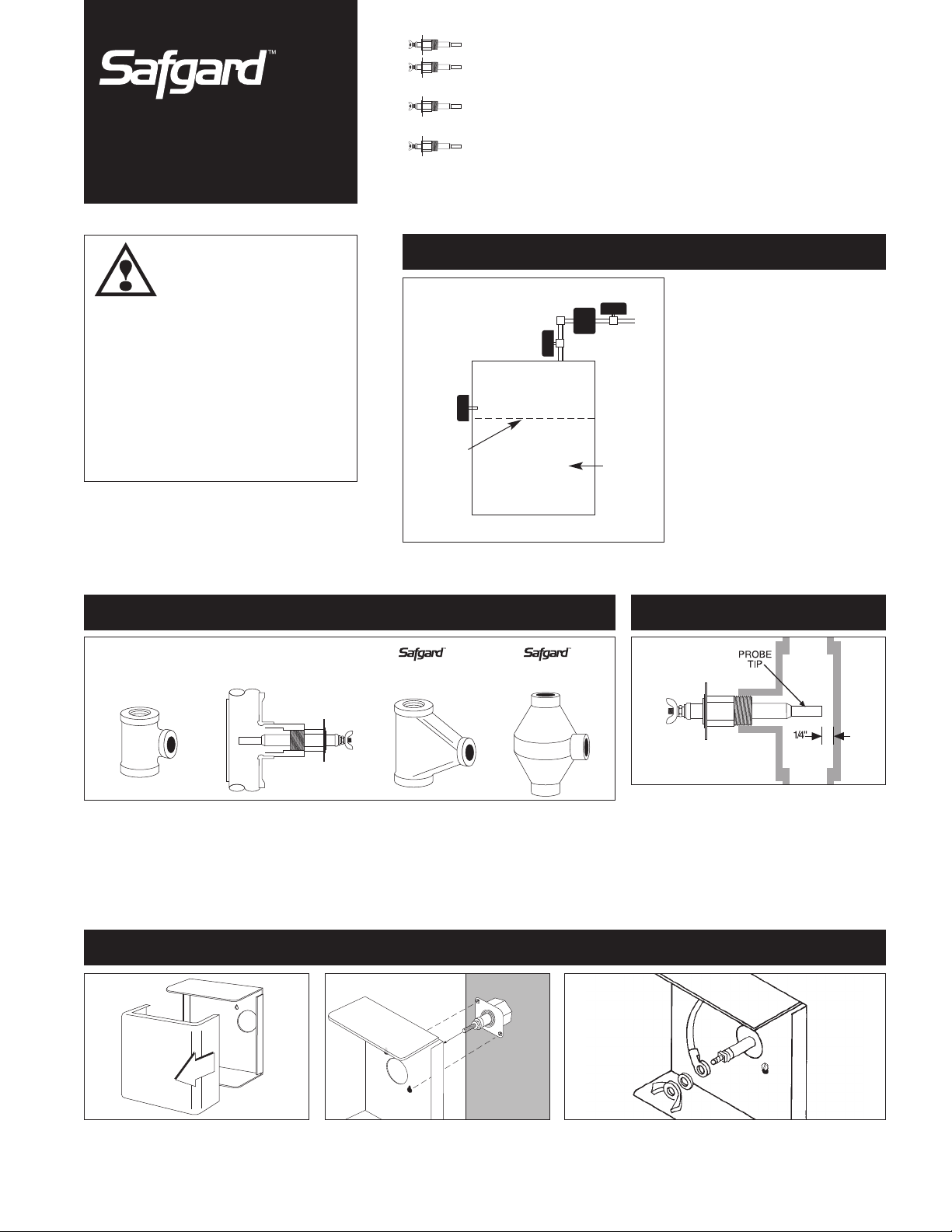
2. Tee Options
STANDARD
REDUCING TEE
(SV Models Only)
FABRICATED TEE
1. Where To Install
HOT WATER BOILER
INSTALLATIONS
B
A
MINIMUM
WATER LEVEL
FOEM-TEE
(160psi)
1214C-2 TEE
(250psi)
C
D
HOT WATER
BOILER
HOT WATER BOILERS: Probe must be
installed at or above the minimum safe
water level established by the boiler
manufacturer. The probe may be
installed directly in the boiler if a suitable tapping is available (A), in the riser
(B), or in the header (C) or (D).
IMPORTANT: To assure proper
drainage, pipe diameter should be no
less than 1" on installations in vertical
piping and no less that 1
tions in horizontal piping.
3. Probe Installation
1
⁄4" on installa-
TEE MOUNTING: If a field fabricated tee is used, make sure that the tee drains thoroughly when the
water level falls below it, and that it conforms to the spacing requirements described in Step 3.
Models equipped with the shorter EL1214-SV probe can be installed in most standard reducing tees.
Safgard cast iron tees are also available to accommodate all probe models (See page 4).
4. Control Mounting
Loosen the two control box cover binding head screws and remove the cover.
Slide keyhole slots over probe mounting
screws and tighten screws (with either a
1/4" hex head driver or flat screwdriver).
Connect the ring terminal wire lead to the probe terminal
stud and secure with the lock washer and wing nut provided.
With the power removed, proceed with installation and
wiring according to Method A or B described on next page.
Check to insure 1/4" clearance from probe to
any surface within the boiler or tee. When
installed in a tee, the probe tip should extend
fully into the pipe run. Apply pipe sealing compound to threads.
Note: Use of Teflon tape is not recommended.
Page 2
P1 P2 A
+
0
LIMIT
CONTROLS
BURNER
CIRCUIT
NEUTRAL
HOT
2
1
ALARM
P1 P2 A
HOT
BURNER
CIRCUIT
NEUTRAL
2
1
BURNER
POWER
SOURCE
(
24 or
120VAC)
P1 P2 A
NEUTRAL
HOT
BURNER
+
0
LIMIT
CONTROLS
2
1
2
P1 P2
A
BURNER
POWER
SOURCE
24 V
AC
1
NEUTRAL
HOT
FACTORY
INSTALLED
JUMPER
1
P1P2 A
ALARM
2
P2 A
24V
AC
1
NEUTRAL
HOT
P1
P1 P2 A
+
0
LIMIT
CONTROLS
BURNER
CIRCUIT
HOT
NEUTRAL
2
1
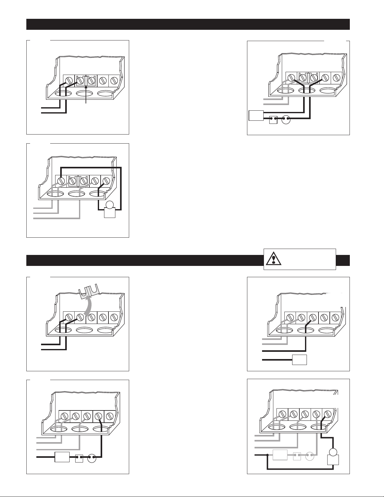
WIRING METHOD A: SAME POWER SOURCE FOR CONTROL AND BURNER CIRCUIT.
A1
A3
䊴
A1 Connect the hot lead of the input volt-
age (24 VAC, 60 HZ) to terminal 1. Connect the
neutral lead to terminal 2. 24 VAC, 60 HZ must
be supplied to terminals 1 and 2 for internal
operation of the control.
䊳䊳
Connect terminal 2 to burner
A2
circuit neutral. Connect terminal P2 to burner
circuit in series with other limit controls.
Consult boiler manufacturer instructions for
proper terminal connections. Control should be
wired in series with and before other circuits.
䊴
A3 Optional alarm connection. Connect
alarm common to terminal 2. Connect alarm hot
to terminal A.
Upon completion of wiring, replace control
box cover.
A2
WIRING METHOD B: SEPARATE POWER SOURCE FOR CONTROL AND BURNER CIRCUIT.
B1
B3
䊴
B1 WARNING! Remove the jumper
between 1 and P1. Connect the hot lead of the
input voltage (24 VAC, 60 HZ) to terminal 1.
Connect the neutral lead to terminal 2. 24 VAC,
60 HZ must be supplied to terminals 1 and 2 for
internal operation of the control.
Connect hot lead from the 24 VAC
B2
䊳䊳
or 120 VAC burner power source to terminal P1.
This terminal supplies power to terminal P2 in
normal operating conditions when water is at
the probe. Connect neutral to burner circuit.
Note: consult boiler manufacturer instructions
for proper terminal connections.
䊴
B3 Connect terminal P2 to burner
circuit in series with and before other limit controls.
Optional alarm connection. Connect
B4
䊳䊳
alarm hot to terminal A. Connect alarm common
to neutral of the burner power source.
Upon completion of wiring, replace control
box cover.
WARNING: Be sure to
remove the jumper
between 1 and P1.
B2
B4
Page 3

OPERATIONAL TEST PROCEDURE
Important: Do not run boiler unattended until the following procedure is completed.
1. After wiring is complete and prior to raising the water level above the probe set the thermostat to call for heat. The burner should not fire. IMPORTANT:
If the boiler fires with no water at the probe, immediately shut down the boiler and refer to Trouble Shooting Instructions below.
2. Proceed to fill the system with water. When water reaches probe position burner should fire. If burner does not fire with water at the probe refer to
Trouble Shooting Instructions below.
MAINTENANCE
When installed on a residential hot water heating system, the probe should be removed and cleaned every five years. When installed on a commercial
application, the probe should be removed and cleaned annually. After cleaning the probe, perform the Operational Test Procedure described above.
TROUBLE SHOOTING
IF THE BURNER DOES NOT SHUT DOWN WHEN WATER DROPS BELOW THE PROBE.
1. Remove power immediately and re-check wiring.
2. Remove power and check for adequate clearance from the probe to any surface within the boiler or tee.
IF THE BURNER DOES NOT FIRE.
1. Make sure water is at the probe and probe lead wire is properly secured to probe.
2. Check for proper ground between probe and boiler shell. Excessive use of Teflon tape or sealing compound may insulate the probe from the
boiler shell.
3. Check to insure probe is not surrounded by an air pocket. Slowly loosen, but do not remove, the probe with a wrench. Allow any air to escape.
When water begins to seep past probe threads, retighten probe.
4. Re-check wiring and test for correct incoming voltage.
A
NEW
VXT Water Feeder with
Digital Feed Counter
D
B
Hydrolevel...
The Safe Choice
C
E
for Every Boiler!
Hydrolevel offers a complete line of electronic
low water cut-offs and liquid level controls,
including the NEW VXT water feeder with
digital feed counter… everything to give you
peace of mind on all
Whether it’s hot water or steam, residential or
commercial, Hydrolevel makes the right control
to complete your installation with safety.
P.O. Box 1847 • New Haven, CT 06508
(203) 776-0473 • Fax (203) 773-1019
TOLL FREE 800-654-0768
www.hydrolevel.com
AA..
el 550 Low Water Cut-Off for hot water boilers,
Mod
dential hot water boilers,
DD..
el VXT-24 Programmable Water Feeder,
Mod
your installations.
BB..
CC..
CG400 foam-compensating Low Water Cut-Off for steam boilers,
Model
Model 170SV Low Water Cut-Off for resi-
EE ..
Model 250WC Pump Contoller/Low Water Cut-Off.
Page 4

FITTINGS
2"
SQUARE
17/8"
313/16"
15
/16"
1"
3
/4" NPT
5
/16"
2"
SQUARE
11/16"
3"
15
/16"
1"
3
/4" NPT
5
/16"
2"
SQUARE
17/8"
49/16"
1"
3
/4" NPT
5
/16"
111/16"
59/16
11/16
51/2
31/16
BACK
37/8
15/8
11/8
15/8
23/8
BOTTOM
Controls equipped with the EL1214-SV Probe can be mounted in standard reducing tees (supplied by others). Safgard manifolds, listed below, can be used
with all probe models.
MODEL PSI SIZE
FOEM-1 160 1 1/2" x 1 1/2" x 3/4"NPT
FOEM-2 160 1" x 1" x 3/4"NPT
FOEM-3 160 1 1/4" x 1 1/4" x 3/4"NPT
1214C-2 TEE 250 1" x 1" x 3/4"NPT
FOEM MANIFOLD 1214C-2 TEE
PROBE DATA
Test Pressure: 1000 PSI, All Models
EL1214 – STANDARD MODEL – 3/4" NPT
For 1/2", order Model EL1220
EL1214-SV – 3/4" NPT
For 1/2", order No. EL1220-SV
EL1214-P – 3/4" NPT
CAUTION: When installing probe, make sure there is a minimum of 1/4" clearance from probe tip to any surface.
DIMENSIONS SPECIFICATIONS
MAXIMUM PRESSURE: 160 PSI
INPUT VOLTAGE: 24 VAC, 60 HZ
SWITCH RATINGS: 5.8 FLA, 34.8 LRA
SWITCH CONTACTS: SPDT
ALARM CIRCUIT: 50 VA @ 24 VAC
LIMITED MANUFACTURERʼS WARRANTY
We wa rra nt pro duc ts man ufa ctu red by
Hydrolevel Company to be free from defects in
material and workmanship for a period of two
years from the date of manufacture or one year
from the date of installation, whichever occurs
first. In the event of any claim under this warranty or otherwise with respect to our products
which is made within such period, we will, at our
option, repair or replace such products or refund
the purchase price paid to us by you for such
products. In no event shall Hydrolevel Company
be liable for any other loss or damage, whether
direct, indirect, incidental or consequential. This
warranty is your EXCLUSIVE remedy and shall be
IN PLACE OF any other warranty or guarantee,
express or implied, including, without limitation,
any warranty of MERCHANTABILITY or fitness
for a particular purpose. This warranty may not
be assigned or transferred and any unauthorized
transfer or assignment thereof shall be void and
of no force or effect.
P.O. Box 1847
New Haven, CT 06508
Phone: (203) 776-0473
FAX: (203) 773-1019
Pilot Duty
45-2400
 Loading...