

Page 1
Model 1150
• ADVANCED SOLID STATE DESIGN
• TEST BUTTON FOR EASY DIAGNOSTICS
• POWER AND LOW WATER LED INDICATORS
Low Water Cut-Off
For Residential
Hot Water Boilers
120 VAC Operating Voltage
WARNING: To prevent electrical shock or equipment damage, power must be off during installation or servicing of the control. To prevent serious burns, the boiler should be thoroughly cooled before installing or servicing control. Only qualified personnel may install or
service the control in accordance with local codes and ordinances. Read instructions completely before proceeding.
Step
• COMPACT SIZE ALLOWS FOR MOUNTING IN TIGHT SPACES
• DESIGNED FOR GAS AND OIL FIRED BOILERS
Step
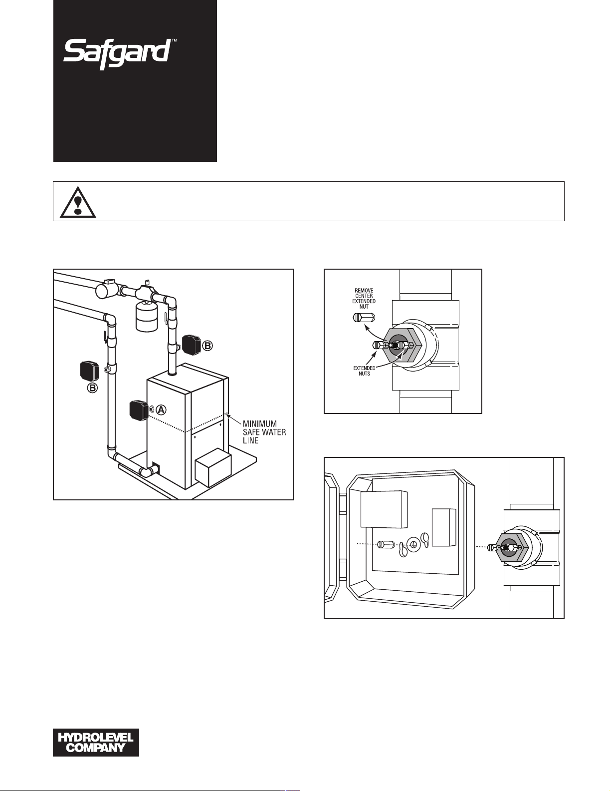
Remove center
extended nut.
Apply pipe
sealing
compound to
probe threads
and install in
boiler or tee.
Tighten so that
the two smaller
extended nuts
are horizontally
aligned.
Determine Mounting Location
The Safgard 1150 must be installed at or above the
minimum safe water level established by the boiler
manufacturer. The 1150 can be installed directly into
the boiler if a suitable tapping is available훽. The
1150 can also be installed in the boiler piping using a
standard 3/4" tee훾.
IMPORTANT: Check for adequate clearance
(minimum 1/4") from metal probe sensor to any
surface inside the boiler or pipe.
Do not install in a location that could hold or trap
water in the event of a low water condition.
Step
Mount the control box on the probe by aligning the
keyhole slots with the two extended nuts. Replace
the center extended nut. Secure the control box by
tightening all three extended nuts.
IMPORTANT: Extended nuts must be tightened
securely for proper grounding.
83 Water St. • New Haven, CT 06511 • Phone: (203) 776-0473 • FAX: (203) 773-1019 • www.hydrolevel.com
Page 2
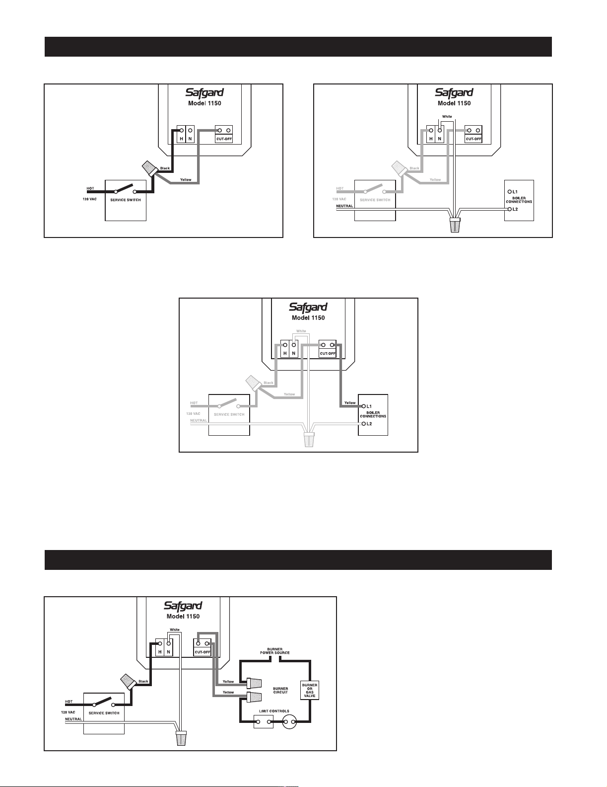
STANDARD WIRING METHOD
This wiring method will shut down all power to the boiler in the event of a low water condition.
USE WIRE NUTS FOR ALL CONNECTIONS
Step Connect the black wire (H) and one of
the yellow wires (CUT-OFF) from the Safgard 1150 to
the hot 120 VAC lead coming from the service switch.
Step Connect the white wire (N) from the
Safgard 1150 to the neutral 120 VAC lead and to the
(L2) boiler connection.
Step Connect the second yellow wire
(CUT-OFF) from the Safgard 1150 to the (L1) boiler
connection.
OPTIONAL WIRING METHOD
This wiring method will interrupt power only to the burner circuit in the event of a low water condition.
USE WIRE NUTS FOR ALL CONNECTIONS
Connect the black wire (H) from the Safgard
1150 to the hot 120 VAC lead coming from
the service switch. Connect the white wire (N)
to the neutral 120 VAC lead. Locate and
break into the burner circuit. Connect the yellow wires (CUT-OFF) from the Safgard 1150
in series with other limit controls as shown.
Page 3

OPERATIONAL TEST PROCEDURE
IMPORTANT: Do not run boiler unattended until the following procedure is completed
1. Before raising the water level above the Model 1150, turn on power to the boiler and set the thermostat to call for heat. Both
the green “POWER” LED and amber “LOW WATER” LED should illuminate. The burner should not fire. IMPORTANT: If the
burner fires with no water at the probe, immediately shut down power to the boiler and refer to the Trouble Shooting instructions below.
2. Proceed to fill the boiler with water. When water reaches the LWCO position, the burner should fire. If the burner does not
fire, refer to the Trouble Shooting instructions below.
3. Turn off the power to the boiler and finish filling the system.
4. Before leaving the job, power up the system and push the TEST button on the Model 1150 to simulate a low water condition.
The amber “LOW WATER” LED should illuminate and the burner should shut down.
MAINTENANCE
EVERY YEAR Check control operation annually by pressing the TEST button. The amber “LOW WATER” LED should illu-
minate and the burner should shut down.
5 YEARS Remove the low water cut-off every five years and clean all surfaces in contact with water.
TROUBLE SHOOTING
IF THE BURNER DOES NOT SHUT DOWN
(when water is below the probe or when the TEST button is pressed)
1. Turn off boiler power immediately and re-check wiring.
2. Turn off boiler power and drain system. Remove low water cut-off and check for adequate clearance – no metal should be in
contact with the controlʼs metal probe tip.
IF THE BURNER DOES NOT FIRE
1. Make sure water has reached the level of the control.
2. Check for proper ground. The 1150 grounds through the probe to the boiler shell or pipe tee. The control box mounting
screws ground the circuit board to the probe. Check to ensure that both mounting screws are tightened securely and that the
probe is not insulated from the boiler shell or tee with excessive use of Teflon tape or sealing compound.
3. Check to ensure the controlʼs metal probe tip is not surrounded by an air pocket. Shut down power to the boiler and
slowly loosen, but do not remove, the control. Allow any air to escape. When water begins to seep past threads, retighten
the control.
4. Re-check wiring and check for correct incoming voltage.
Page 4

DIMENSIONS
SPECIFICATIONS
VOLTAGE 120 VAC, 60 HZ
BURNER CONTACTS 5.8 FLA, 34.8 LRA, 125 VA pilot duty @ 120 VAC, 60 HZ
MAX PRESSURE 160 PSI
MAX WATER TEMPERATURE 250°F (121°C)
LIMITED MANUFACTURERʼS WARRANTY
We warrant products manufactured by Hydrolevel Company to
be free from defects in material and workmanship for a period
of two years from the date of manufacture or one year from
the date of installation, whichever occurs first. In the event of
any claim under this warranty or otherwise with respect to our
products which is made within such period, we will, at our
option, repair or replace such products or refund the purchase
price paid to us by you for such products. In no event shall
83 Water St. • New Haven, CT 06511 • Phone: (203) 776-0473 • FAX: (203) 773-1019 • www.hydrolevel.com
Hydrolevel Company be liable for any other loss or damage,
whether direct, indirect, incidental or consequential. This warranty is your EXCLUSIVE remedy and shall be IN PLACE OF
any other warranty or guarantee, express or implied, including, without limitation, any warranty of MERCHANTABILITY or
fitness for a particular purpose. This warranty may not be
assigned or transferred and any unauthorized transfer or
assignment thereof shall be void and of no force or effect.
 Loading...