

Hydro Leduc TXV Indexable Instruction Manual
HYDRO LEDUC HYDRO LEDUC GmbH HYDRO LEDUC N.A., Inc. HYDRO LEDUC AB
Siège social et usine Haselwander Str. 5 19416 Park Row - Suite 170 Betongvägen 11
BP 9 - F-54122 AZERAILLES (FRANCE) D-77746 SCHUTTERWALD (DEUTSCHLAND) HOUSTON , TEXAS 77084 (USA) 461 38 Trollhättan
Tél. +33 (0)3 83 76 77 40 Tel. +49 (0) 781-9482590 Tel. +1 281 679 9654 +46 (0)520-10 820
Fax +49 (0) 781-9482592 Fax +1 281 596 0903
EN_TXV_INDEXABLE_2016_06
Instructions TXV Indexable
Read before installation of the pump
IMPORTANT!
1 2
3
4
5
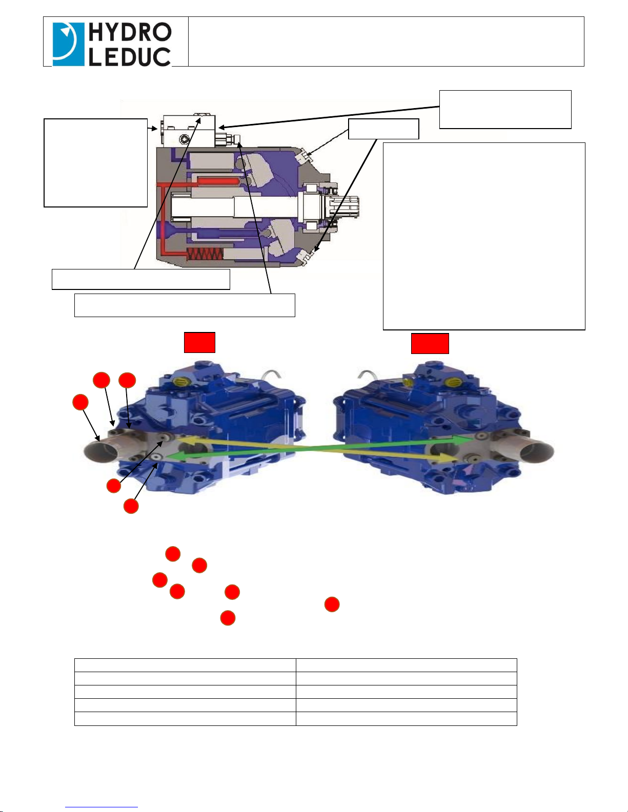
HOW TO CHANGE ROTATION DIRECTION ON THE PUMP:
Remove the 4 screws. 1
Remove the 2 flange halves 2
Remove the fitting 3
Switch place on screw 4 and plug 5 and reassemble fitting on the other port
NOTE: Do not rotate the pump shaft before the set screw 4 is in place.
NOTE: Rotation adjustment screw 4 is always the output side of the pump.
Calculation of suction hose:
Flow
Size suction hose
0-65
1 ½” / 38 mm
0-120 l/min
2” / 50 mm
120-160 l/min
2 ½” / 63 mm
160-250 l/min
3” / 76 mm
This is valid when tank is place above the pump.
When tank is placed beside or under the pump the max flow/ hose size should be reduced.
LS Drainage:
Connect at least
10 mm (½ ") hose
direct to tank to
prevent back
pressure.
Pressure limit. Factory set at ~100bar
Stand-by Pressure control. Factory set at 30 Bar
Connect all hoses to the pump.
The pump should get oil through the
drainage hose. Make sure the pump has oil
using the bleed screw.
Open the bleed screw (don’t unscrew
completely) and check if oil comes out.
If no oil comes, remove the screw
completely and manually fill the pump
with oil. Mount the screw and tighten.
Start up the hydraulic system on low speed
Start an operation to evacuate any
remaining air in the tubing and pump.
Bleed the LS line.
Bleed Screw
LS Connection on opposite
side of regulator
CCW
CW
HYDRO LEDUC HYDRO LEDUC GmbH HYDRO LEDUC N.A., Inc. HYDRO LEDUC AB
Siège social et usine Haselwander Str. 5 19416 Park Row - Suite 170 Betongvägen 11
BP 9 - F-54122 AZERAILLES (FRANCE) D-77746 SCHUTTERWALD (DEUTSCHLAND) HOUSTON , TEXAS 77084 (USA) 461 38 Trollhättan
Tél. +33 (0)3 83 76 77 40 Tel. +49 (0) 781-9482590 Tel. +1 281 679 9654 +46 (0)520-10 820
Fax +49 (0) 781-9482592 Fax +1 281 596 0903
EN_TXV_INDEXABLE_2016_06
Instructions TXV Indexable
Read before installation of the pump
Selection of Oil:
Please consider the following recommendations
mineral oil
Start-up and adjustment of TXV Pump:
Ensure that the technical parameters of the PTO are compatible with the use of indexable TXV pump (necessary
torque, continuous operation, weight torque.
See HYDRO LEDUC variable displacement Pump Catalogue for the pump characteristics.
Check the direction of rotation of the pump according to the PTO. If you look at the front of the PTO, the rotation is
clockwise, then the pump rotation must be counter-clockwise (and vice versa).
Installation of pump onto PTO:
Make sure there is a front square seal placed correctly in its groove. Do not use paper seals.
- If no recommendation from the PTO Manufacturer, lube the splines with graphite grease.
- Install the pump on the PTO and ensure the tightening torque of all bolts conforms to the PTO manufacturer's
recommendation.
Use cylindrical connectors provided with a seal to ensure perfect tightness. ‘
P G1 ¼”
Drain G ½”
LS G ¼”
Suction TXV Flange
The inner diameter of the suction pipe must be in accordance with the table on the first page.
This supply line should be as short as possible to facilitate the oil supply to the pump.
The drain line from the LS valve assembly should be properly sized and must be connected directly to the tank
The pump should always be below the oil level in the tank.
This is to ensure that no air intake is possible when the pump is not used for some time.
Connect the LS port on the pump directly to the LS port on the proportional valve.
The plastic tube on the front of the pump should be attached to a hydraulic hose. Be careful not to bend it,
It identifies any leaks in the shaft seals.
Settings on the pump:
■ Standby setting: The TXV pumps supplied from the factory has a standby pressure of 30bar
(Adjustable on request from 25 to 60 bar).
■ Maximum pressure: pressure cap (PC) must match the maximum working pressure of your installation.
- Either: Enter the PC pressure you need when you order - or the pump will come standard pressure
setting of 100 bar, when installing, adjusting screw to set the desired pressure.
■ valve in the intake plate of the proportional valve: Must be set 25 to 30 bar higher than the chosen PC
pressure.
Periodic inspection (1 or 2 times per year):
- Periodically check the tightness pump on the PTO;
- Regularly check the absence of oil in the air valve connected to the pump.
For environmental oil Please contact HLAB for verification.
Viscosity
20 to 40 cst
Minimum Viscosity
5 cst
Viscosity of the optimal operation
Values above 400 cst can damage the pump
10 to 400 cst
Cleaness class
class 9 NAs 1638
class 6 SAE
class 20/18/15 ISO ISO/DIS 4406
Max temperature
100°C
 Loading...