

Hydro Instruments HC-220 Operation And Maintenance Manual

HC-220 PID Controller
Operation and Maintenance Manual
The information contained in this manual was current at the time of printing. The most current versions of all
Hydro Instruments manuals can be found on our website: www.hydroinstruments.com
HC-220 Rev. 11/1/18
1

HC-220 PID Controller
Operation & Maintenance
Manual
Table of Contents
Safety Precautions .............................................................................................................3
I. Overview ...........................................................................................................................3
II. Control Features ................................................................................................................4
III. Confi guration Mode ..........................................................................................................7
IV. Input And Output Calibration ...........................................................................................9
V. Operation Mode ..............................................................................................................11
VI. Alarm & Output Features ................................................................................................12
VII. Reference Terms .............................................................................................................13
VIII. Troubleshooting ..............................................................................................................15
Flow Charts and Drawings
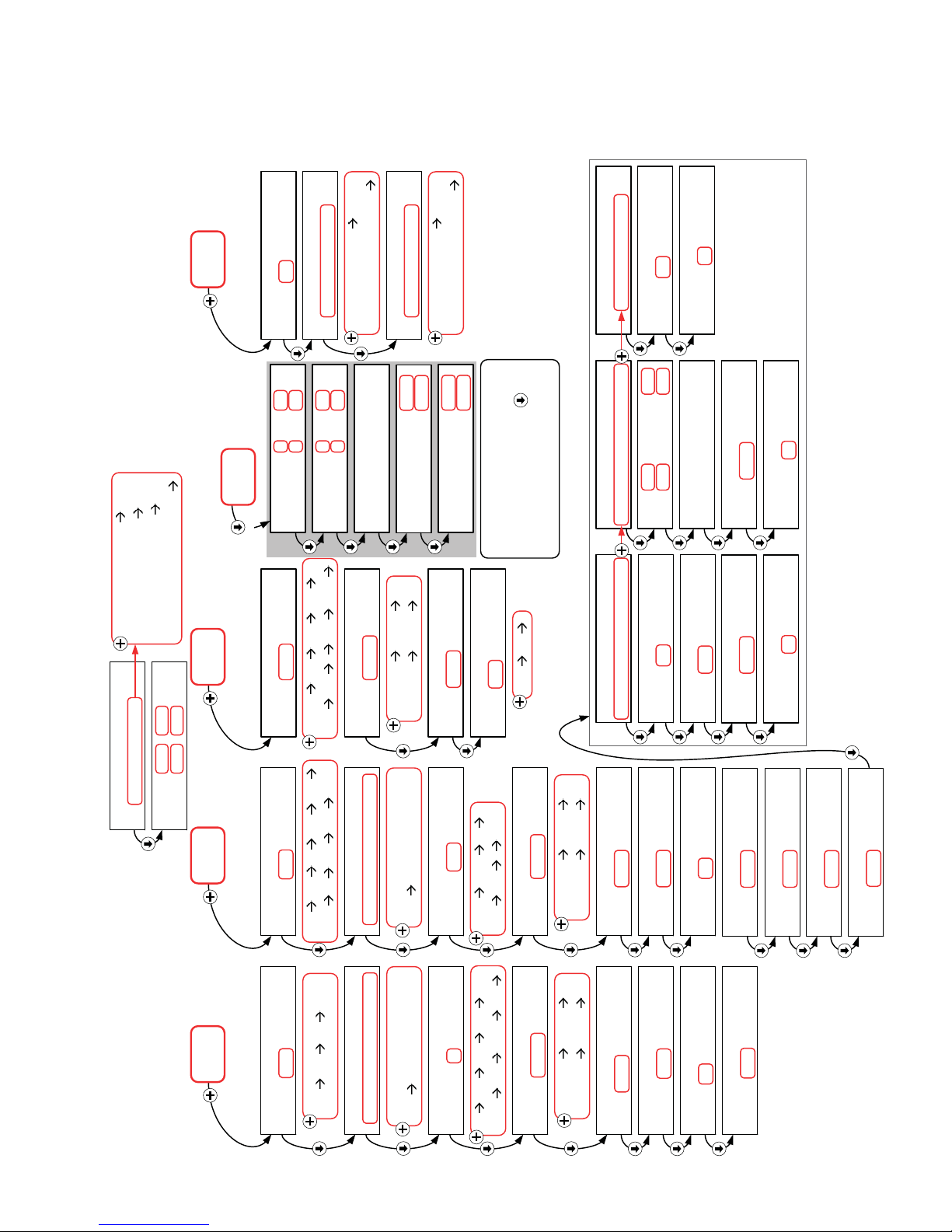
Figure 1 Confi guration Mode Flow Chart ...............................................................5
Figure 2 Hidden Screens .........................................................................................6
Figure 3 Operation Mode Flow Chart ...................................................................10
Figure 4 Circuit Board Drawing ............................................................................16
RIGHT TO REVISE: Hydro Instruments reserves the right to make engineering
revisions and improvements at any time. Please contact Hydro Instruments if there
is any discrepancy between the literature and the product provided.
2

SAFETY PRECAUTIONS
GENERAL: Be sure to follow all applicable and prudent safety precautions when working with chemicals
and electrical equipment.
ELECTRICAL: The circuit board and incoming A/C power line do include electrical shock risk. Take care
to avoid electrical shocks and do not touch any part of the circuit board or A/C power line unless you are certain
that A/C power has been disconnected from the system.
When connecting A/C power to the instrument, it is imperative that the A/C source be well grounded. Insuffi cient
A/C grounding will disrupt proper operation of the instrument.
CHECK FOR DAMAGE: Before removing the product from the shipping packaging, carefully check the
equipment for damage. If any product is found damaged, do not put it into operation or install it. Contact
Hydro Instruments to discuss repair or replacement of the damaged equipment.
I. OVERVIEW
1. Modes of the HC-220 – The HC-220 PID Controller has 2 modes that can be accessed. These modes are
as follows:
a. Confi guration Mode – This mode is used to set up the control and display parameters. (Flow Meter
range, Control type, Display units, alarms, etc…)
b. Operation Mode – This is the mode used during operation of the HC-220 PID Controller. It allows for
Dosage and Set Point Adjustments as well as manual control of the chemical feed rate.
2. Switching Between Modes – The Confi guration Mode is password protected. The password is 220.
This can be entered by using the
a. Operation Mode – This is the HC-220 standard mode. This can be reached from either of the other
two modes by repeatedly pressing the “up arrow”
b. Confi guration Mode – This mode is accessed from the Operation Mode by pressing the “down arrow”
key until the password screen is reached. Then enter the password “220” and then press the “down
arrow”
3. Menus & Display – Within each “Mode” there is a set of “Parameters”. Parameters are represented by
the blocks in the following fl ow charts. To move between these parameters, use the “up arrow” and
“down arrow”
4. Control Methods – The HC-220 offers four different control methods. They are Flow Pacing (Propor-
tional), Residual/ORP, Compound Loop Control, and Manual Control. The method is selected within the
“Confi guration Mode”. (See Section III.)
key.
keys.
and buttons.
key.
5. Electrical Inputs – The HC-220 offers two analog input channels standard. The PV1 input channel is
used only for a Flow (e.g. proportional) signal. The PV2 input channel is used only for a Residual (e.g.
set point) signal. A third, optional analog input is sometimes included. The optional PV3 input channel is
used only for remote adjustment of the Set Point setting. Each channel can be set to accept either 4-20mA
or Modbus RS-485 signals. Each of the process variable inputs are individually selectable to be read over
any of the four analog input channels AI1, AI2, AI3, or AI4 and also over Modbus.
3

NOTE: The HC-220 can power the 4-20mA source via 24VDC for both the PV1 and PV2 inputs (e.g.
loop powered input). This will change how these inputs are connected. Refer to Figure 3 for additional
details.
PV1(Flow)
AI1/V- = Source powered 4-20mA input.
AI1/V+ = Loop powered 4-20mA input.
PV2 (Residual)
AI2/V- = Source powered 4-20mA input.
AI2/V+ = Loop powered 4-20mA input.
6. Electrical Outputs – The following outputs are available:
a. The HC-220 includes two (2) SPDT alarm relays. Each relay can be independently selected as either
representing normal alarms or whether the HC-220 is in AUTO or Manual mode.
b. 4-20mA Output – The HC-220 is equipped with two (2) 4-20mA outputs which are used to control
chemical feed rate.
7. RS-485 Modbus Communication – This feature allows the HC-220 to be monitored and controlled by a
computer. See Hydro Instruments’ Modbus Communication Setup document for further details.
II. CONTROL FEATURES
1. Keypad Operation – The keypad is used in all three modes of the HC-220. Generally the keys are used
as outlined here below. However, detailed instructions will follow.
a.
b.
2. Dip Switches – These switches are used to select whether the analog input channels are to be used for
0-10 Volts or 4-20mA.
a. Switches 1 and 2 on the MB124 circuit board are used for the PV1 (Flow) input channel.
4-20mA: 1 = On, 2 = Off
0-10V: 1 = Off, 2 = On
b. Switches 3 and 4 on the MB124 circuit board are used for the PV2 (Residual) input channel.
4-20mA: 3 = On, 4 = Off
0-10V: 3 = Off, 4 = On
& keys – These keys are used to cycle through the various display screens. These keys will be
referred to as “up arrow” and “down arrow”.
& keys – These keys are generally used to adjust settings and values within the screen being
displayed. These keys will be referred to as “plus” and “minus”.
4
ALM
OUT
HOLD
Alarm Delay Time
AI1 Cal: 4 mA 20 mA
FIGURE 1
CONFIGURATION MODE
Normal Alarms
10 secs
AI2 Cal: 4 mA 20 mA
Output Relay 1 Usage
AI3 Cal: 4 mA 20 mA
Auto(Off)/Manl(On)
Normal Alarms
Input Value
Was Changed!
AI4 Cal: 4 mA 20 mA
Output Relay 2 Usage
Normal Alarms
A01 Cal: 4mA= 803
20mA= 3992
Normal Alarms
A02 Cal: 4mA= 800
Auto(Off)/Manl(On)
20mA= 4000
are hidden screens,
accessed by holding -
Screens shown with grey border
at the appropriate screen
nd
to last in the branch)
(typically 2
Lag Time Mode
Lag Time Mode
Fixed Lag Time
Res Lag Time
60 secs
Res Reset Value
0 GPM
2 Point Var Lag Time
FA1= 50% TA1= 60s
FA2= 75% TA2= 40s
A= 0.0 F= 0
B= 0.0 T= 60
Maximum Lag Time
1800 secs
Res Reset Value
0 GPM
Flow Pacing
Control Type
Residual/ORP
Compound Loop
Dual Input Feed Fwd
10.0 KG/H
PPM
Out Gas Feed Type
PPM MG/L mV
2
Cl
pH NTU %
Cl2 SO2
Res Decimal Posn
Lag Time Mode
1 Point Var Lag Time
00.00 0.000
00000 000.0
00.00
Res Full Scale
5.00 PPM
Flow at Variable Lag
60 secs
0.00 PPM
Res Filter Time
500 GPM
10 secs
Maximum Lag Time
Res Low Set
1800 secs
0.00 PPM
Res Reset Value
Res High Set
0 GPM
5.00 PPM
Res Dead Band
0.10 PPM
Res Integral Value
20.0 %
Res Lag Time
Res Minimum Value
OUT
000.0 00.00
Output Units
KG/H
SETUP: FLO RES
OUT ALM
Flow Pacing
Res Input Name
RES
KG/H GPH GPM GPD
RES ORP pH Ch1 SCM
O PRO
Output Decimal Posn
LPM LPH % PPD GR/H
TDS DO CON TUR PV2
Input Signal Loss
2
0.000 00000
000.0
Maintain Valve Posn
Maintain Valve Posn
Output Full Scale
Close Valve
Res Units
FLO RES
Flow Input Name
FLO
Close Valve
FLO PV1 H
Maintain Valve Posn
Input Signal Loss
Maintain Valve Posn
Flow Input Units
%
% GPM MGD LPM
MLD GPD M3/H LPH
Flow Decimal Posn
000.0
000.0 00.00
0.000 00000
Flow Full Scale
10.0 %
Flow Threshold
0.0 %
Flow Filter Time
10 secs
Flow Low Set
0.0 %
5
 Loading...