

Page 1
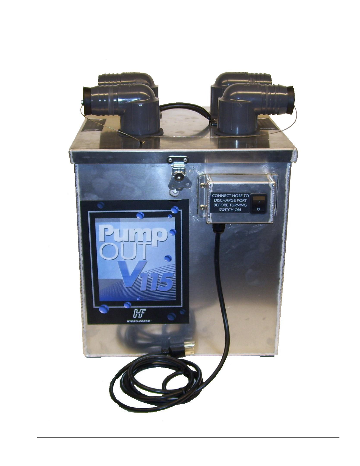
V115 PUMP OUT MANUAL
AC12H
REVISED: 03.14.2019
Page 2

2
Introduction
Congratulations on your purchase of the Hydro-Force V115 Pump-out. The V115
is designed to give performance combined with versatility. Years of experience,
engineering, and planning have gone into the design and manufacturing of the
V115. We take a great deal of pride in the V115 Pump-out; our goal is no less than
your complete satisfaction.
This manual will provide users with the knowledge required to operate the V115
Pump-out safely, to understand how to properly operate and maintain the
machine, and to ensure that the equipment operates at its maximum performance
level.
All users must read and understand this manual completely before
operating the machine.
Always maintain this manual in legible condition adjacent to the V115 Pump-out,
or place in a secure location for future reference.
Any questions pertaining to the operating or servicing of this unit should be
directed to your nearest Hydro-Force distributor.
This manual is written specifically for the V115 Pump-out units manufactured by:
Aramsco
4282 S 590 W
Salt Lake City, UT 84123
801-268-2673
801-268-3856 FAX
Information in this manual is subject to change without notice and does not
represent a commitment on the part of Hydro-Force or its parent or affiliated
companies.
Page 3
3
Technical Specifications
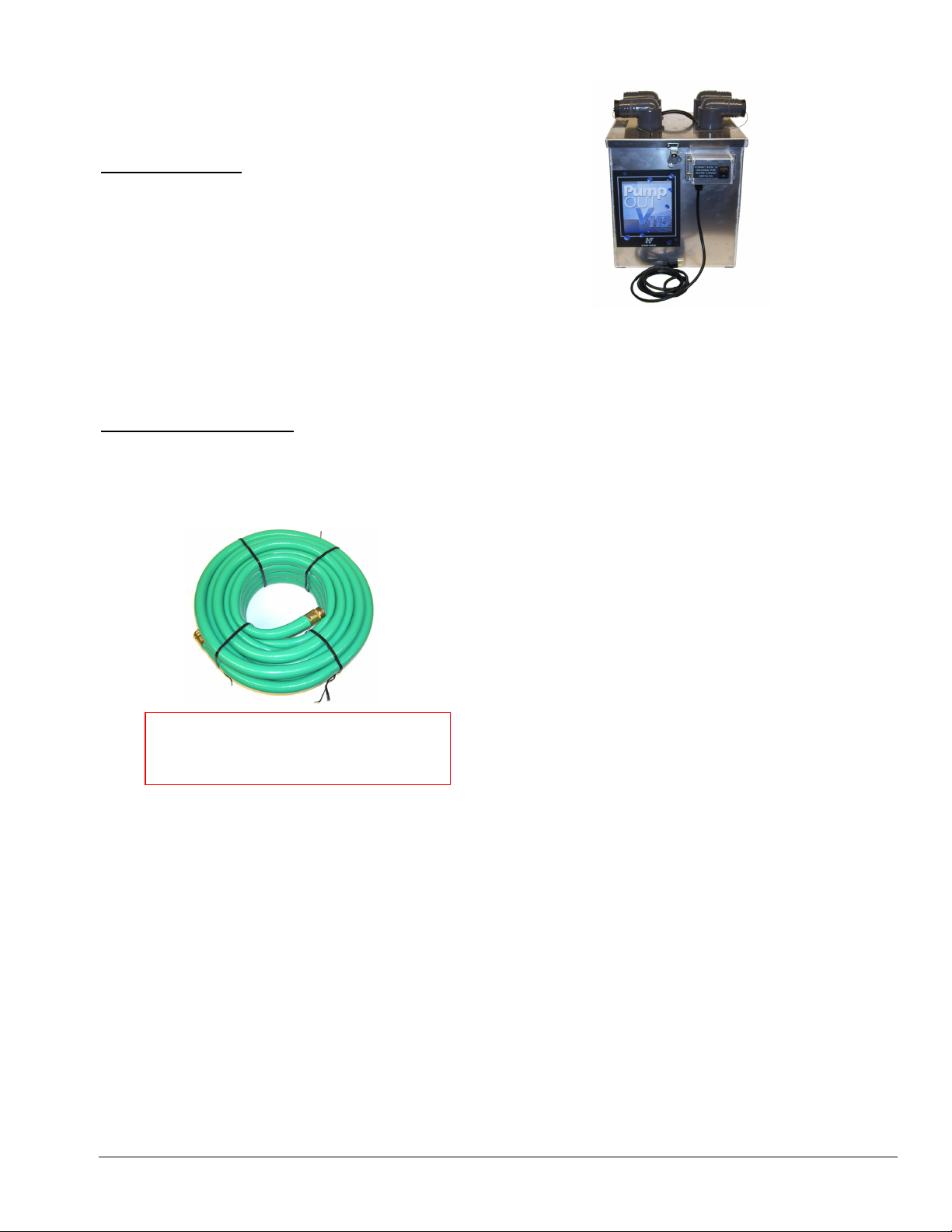
AH65
V115 Pump-out
Height: 18-1/2”
Length: 15”
Width: 14-3/8”
Weight: 28.4lbs.
Tank Capacity: 11 gallons
Pump-out Pump: Little Giant 115VAC 8-20 gpm
Maximum psi 11.4 – Maximum pumping height 26 ft.
Power Draw: 5.00amps Waste Pump
andard Equipment
St
V115 Pump-out Tank Unit
Pump-out Hose: 50’ x 3/4” with male & female garden hose fittings
50’ X 3/4” Pump Out Hose
Page 4
4
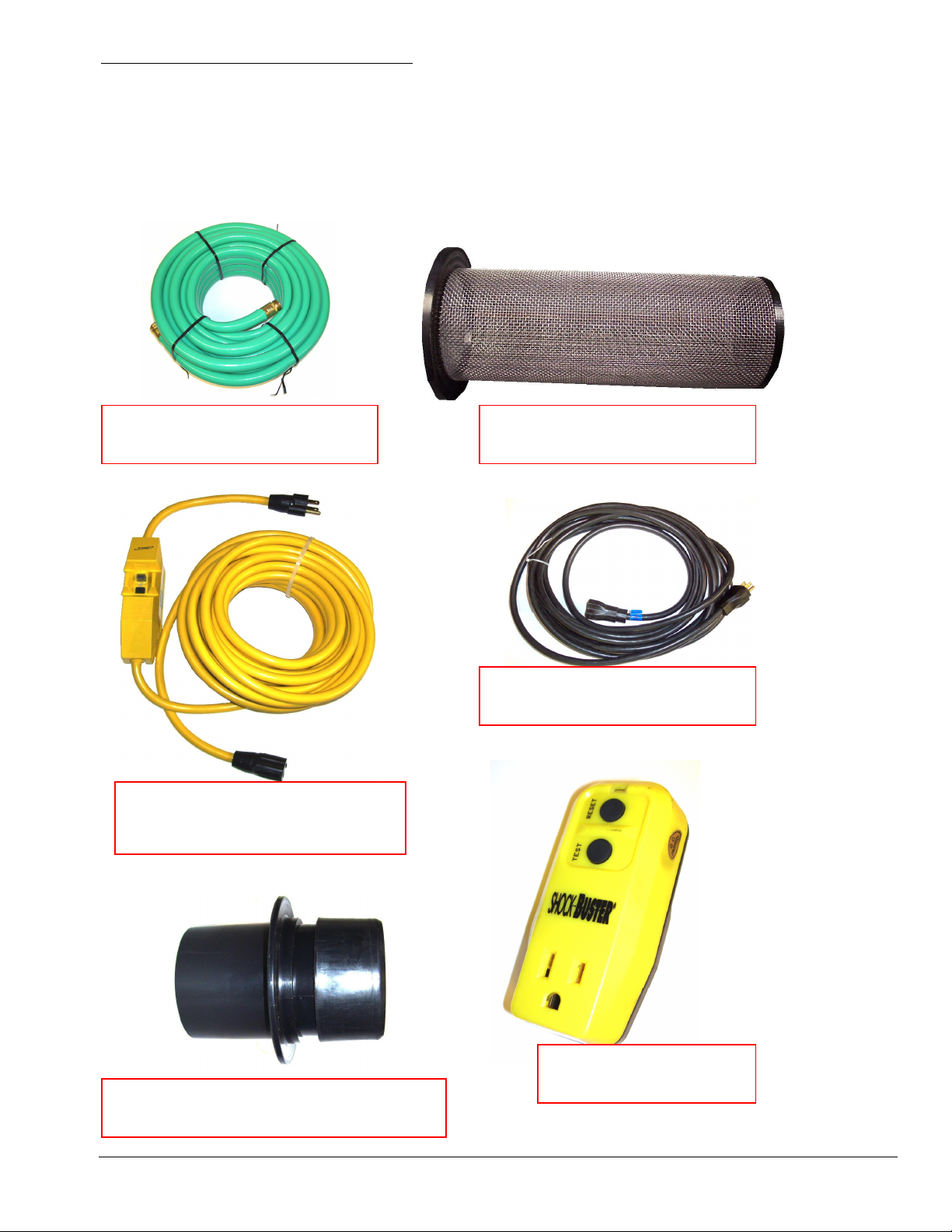
Additional / Optional Equipment
Extra Pump-Out Hose 3/4” x 50’: AH65
Replacement SS Filter: AC11S
GFCI Protected Extension cord 12/3 x 50’: NM4407
Extension Cord 12/3 x 50’: AX33
Shockbuster - External GFCI Protector: AX126
2” Flash Cuff Male Starter Cuff AH203
AH65
50’ X 3/4” PUMP OUT HOSE
NM4407
50’ X 12/3 CORD WITH GFCI
AC11S
SS FILTER SCREEN
AX33
50’ X 12/3 EXTENSION CORD
AX126
SHOCKBUSTER GFCI
AH203
2” FLASH CUFF MALE STARTER
Page 5

5
Safety
Section
1
CAUTION! This machine is an electrical appliance. Care must be
taken to reduce the risk of electrical shock.
• READ AND UNDERSTAND ALL INSTRUCTIONS BEFORE OPERATING THE V115 Pumpout.
• To reduce the risk of property damage or injury, repairs to electrical systems should only be performed by
experienced technicians. Contact your distributor for assistance.
• Unplug machine power cord from outlet before performing any repairs on the pump-out.
• Plug unit into grounded outlets only. Do not remove
Interrupting (GFCI) device will reduce the risk of electrical shock.
• Do not use the V115 Pump-out in standing water or on wet surfaces.
• Do not store the V115 Pump-out in wet conditions.
• If V115 Pump-out is leaking, unplug power cord from outlets before approaching or touching machine.
• Do not unplug power cord by pulling on the cord. Grasp the plug when unplugging the cord.
• Do not pull the V115 Pump-out by the cord.
• If cord or plug is damaged, do not use cord. Replace with new cord or repair as needed before use.
ground prong from plug. Use of a Ground Fault Circuit
Page 6

6
WARNING! This machine must be protected from conditions which may
damage the pump, tank, hoses and other components.
• Freezing of water in this machine will cause serious damage. The V115 Pump-out and hoses must be
protected from freezing temperature. Store, transport, and use this equipment only in temperatures well above
freezing. (32ºF or 0ºC). If you suspect the V115 Pump-out has been frozen, do not plug in or turn on machine
until you are sure it has thawed completely.
• If the equipment cannot be stored or transported in a warm environment, it can be guarded from freezing by
running an anti-freeze solution through the pump. The V115 Pump-out is filled at the factory with anti-freeze
to eliminate damage during shipment in cold weather.
• The V115 Pump-out must not be used to pump flammable
these materials may be present.
• Rinse the V115 Pump-out tank and pump with fresh water after each day’s use.
• Do not allow pump to run dry. Do not by-pass the float switch to operate the pump.
• Examine the pump-out hose before each use and replace or repair hose as needed.
• Clean the V115 Pump-out tank daily to keep pump-out pump from becoming clogged.
• Keep Vacuum Filters clean and check float switch for proper operation.
• Drain V115 Pump-out tank before moving unit. Lift using only the handle or support tank from underneath.
• Water may be spilled, drip, or be exhausted from discharge port or hose connections during operation. Place
unit in area where water will not cause damage or use drop cloth to protect surfaces.
or combustible materials or used in areas where
Page 7
7
Operation Procedures
Section
2
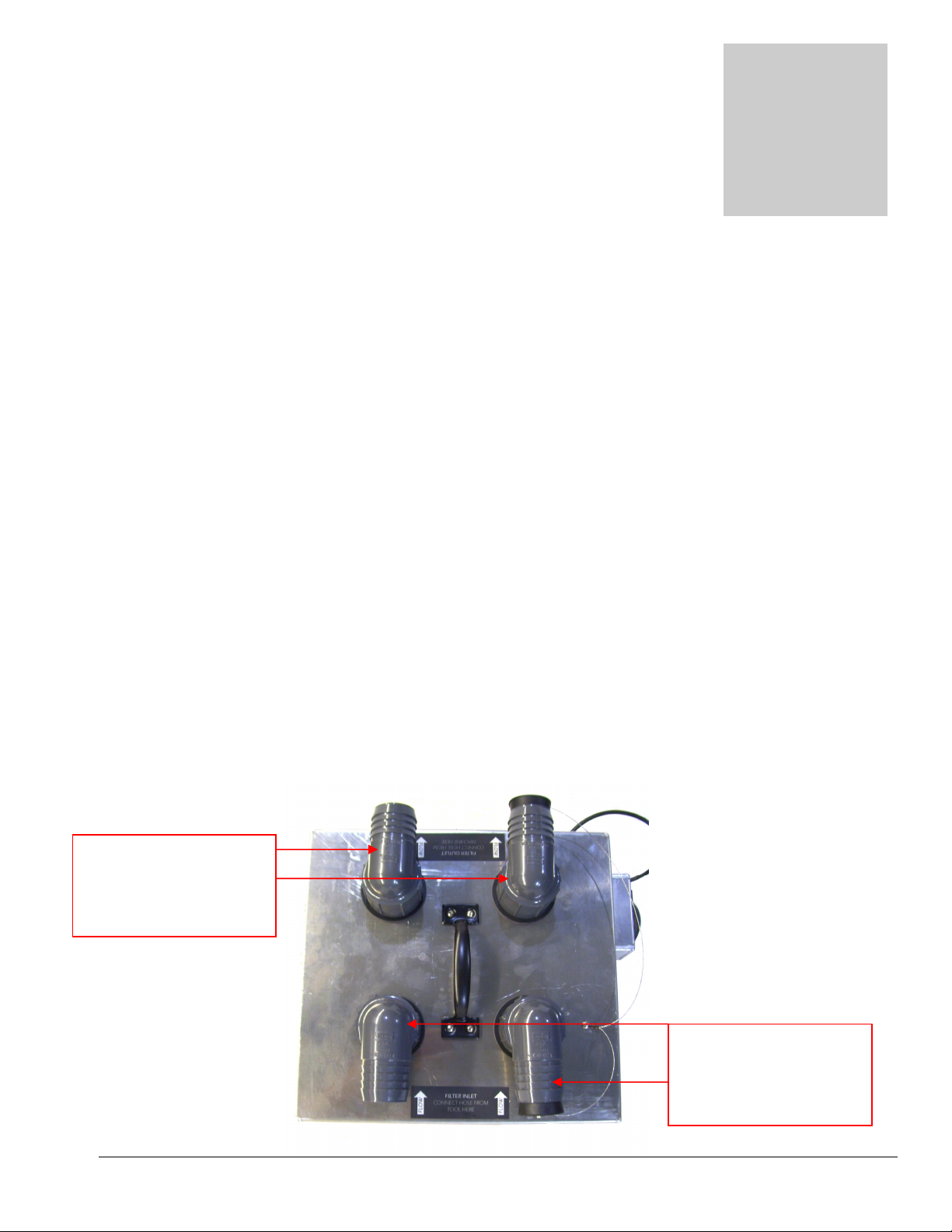
OUTLET SIDE
–
INLET SIDE
–
Knowledge of the proper operation of the V115 Pump-out is required to
ensure user safety and efficient performance of the extractor.
SET UP AND OPERATION
Vacuum Hose Connection:
Connect the hose cuff from the 2” vacuum hose coming from the cleaning tool to one of the 2” hose barbs
on the inlet side of the V115 Pump-out. If you are using two tools the second hose can be connected to the
other barb. If you are only using one tool keep the rubber stopper in the second barb. Arrows indicate the
direction of the airflow from the tool to the extractor.
Connect the hose cuff from the 2” vacuum hose coming from the extractor to one of the 2” hose barbs on
the outlet side of the V115 Pump-out. If you are using two tools the second hose can be connected to the
other barb. If you are only using one tool keep the rubber stopper in the second barb.
For “4 to the Door” operation connect two 2” vacuum hoses to t
V115 Pump-out tank. A single 2” vacuum hose can run from one inlet port to the tool.
Starter Cuffs can be used to connect Flash Cuffs to the V115 Pump-out. Connect 2” Flash Cuff Male Starter
Cuffs (AH203) to the 2” hose barbs on the inlet side of the V115 Pump-out. Then connect your 2” Female
Flash cuffs. Standard 2” hose cuffs can still be used on the outlet side of the V115 Pump-out.
Connect this side
to EXTRACTOR
he barbs on the outlet side of the
Connect this side
to the TOOL
Page 8
8
Electrical Connection:
Plug an extension cord into an 115v AC wall outlet. Use a GFCI protected outlet, a GFCI protected cord or
an external GFCI device to reduce the risk of electrical shock.
The V115 Pump-out only draws 5amps of power so most household outlets will safely handle the load.
If a circuit breaker trips during operation, reset the breaker and move the cord to another outlet as needed.
Connection of Pump-out Hose:
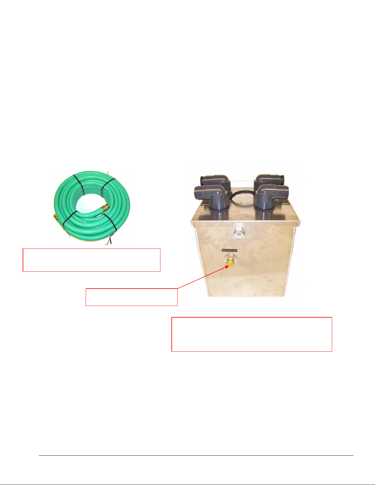
The pump-out hose is a 50’ section of 3/4” garden hose.
• Remove the cap from the pump-out discharge port fitting on the side of the tank.
• Connect the pump-out hose to the discharge port fitti
• Place the other end of the hose in a commode or drain connected to the sanitary sewer system.
• Secure hose end to prevent movement during pumping.
When ready to begin cleaning, turn the V115 Pump-out power switch to the ON position.
• Do not turn on waste pump switch unless pump-out hose is connected and has been routed
to a proper drain.
ng.
Pump-out Hose – AH65
3/4” id X 50’ with M-F Garden Hose Fittings
DISCHARGE PORT
Connect the Female Garden Hose Fitting end of the
Pump-out Hose to the pump-out discharge port fitting
on the side of the tank. Place the other end of the
pump-out hose in a sanitary drain.
Page 9

9
Shutdown Procedures:
Turn the V115 Pump-out power switch to the OFF position and disconnect the power cord.
Disconnect the pump-out hose from the discharge port fitting and replace the cap.
Roll up the pump-out hose toward drain to remove remaining water from hose.
Connect ends of hose together to prevent dirty water from dripping from hose during transport.
Disconnect the vacuum hoses.
Clean the filter screens as needed. Replacement filter screens are available (AC11S.)
Empty the remaining water from the tank and rinse out the tank.
• Disconnect the power cords from the outlets and from
• Roll up all hoses and cords. Collect and store V115 Pump-out, all tools, and accessories.
the machine.
Page 10
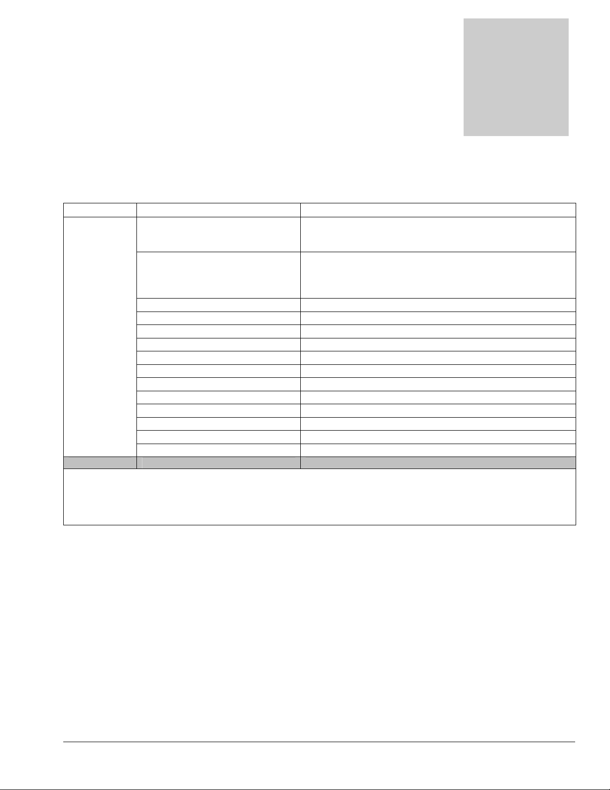
Problem
Cause
Solution
Section
2
Troubleshooting
Troubleshooting –
V115 Pump-out
Pump-out not
working Building circuit breaker tripped.
GFCI tripped
Faulty power cord Replace cord (AX33 or NM4407)
Faulty switches or internal wiring Check wiring & test switch - Repair as needed * (NM5008)
Pump-out pump faulty Replace pump-out pump (NM5053)
Pump-out pump clogged Clean pump-out – Clean filter screens - Keep tank clean
Outlet check valve stuck Clean or replace check valve
Discharge hose restricted Un-kink, clean out or replace hose
Float switch stuck Clean switch make sure float slides up & down easily
Float switch faulty Replace float switch (NM5054)
Reset breakers or move cords to other outlets. Repeated
tripping of breaker may indicate a short circuit. Check cord
and unit wiring and repair before using pump-out.*
Reset GFCI, replace GFCI or move to other outlet
Repeated tripping of GFCI may indicate a short circuit.
Check cord and unit wiring and repair before using pumpout.*
* To reduce the risk of fire electrical shock or injury repairs to wiring should only be performed by
experienced service technicians.
If you are not experienced in checking electrical wiring contact your nearest authorized service
center to perform tests and repairs to cords, wiring and switch.
• Contact your distributor for additional troubleshooting
assistance, to order parts, or for advice and assistance in
performing necessary repairs.
10
Page 11
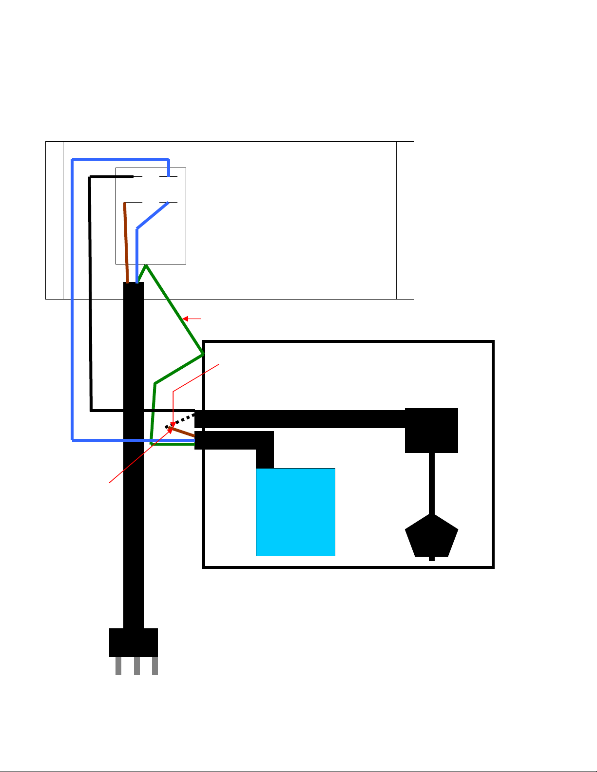
V115 Pump-out
BLACK
BLUE BLUE BROWN
GREEN
Wiring Diagram
BLUE
BROWN
WHITE
GREEN
PUMP
11
Page 12

Maintenance
Section
3
Proper maintenance is required to keep the V115 Pump-out operating properly,
prevent downtime and to extend the life of your equipment.
WARNING: Disconnect electrical power before performing any service or
maintenance inside switch box or before testing or repairing the pump, switches or
power cord. Failure to do so may result in severe personal injury or death.
CLEAN THE FILTERS:
Build-up of debris in the Stainless Steel filters will reduce the vacuum air flow and may cause a significant
decrease in water recovery. A damaged filter screen will allow debris past the filter and into the pump-out
tank. This debris can clog the Waste Pump and the Float Switch Assembly. Clean the filter screens after each
use and replace the filters if damaged.
CLEAN THE TANK:
Build-up of fine silt and debris can damage the Waste Pump. Clean out the tank on a regular basis to extend
the life of these components as well as keep the tank looking and smelling better.
• Remove the tank lid and lay the tank on its side near
• Use a hose to rinse the dirt and debris out of the recovery tank.
• Close the drain valve and spray the tank with a deodorizer or disinfectant.
• Dispose of the dirty water and debris.
• Clean the outside surface of the tank.
• Wipe off the cord and hose. Examine hose and cord after each use and repair or replace as needed.
a drain.
CLEAN WASTE PUMP-OUT PUMP:
Build-up of fine silt inside the Waste Pump can clog the pump.
• After cleaning out the tank, remove the cap from the discharge port and connect the Pump-Out hose
to the discharge port fitting on the side of the tank; run the hose to a drain..
• With the cord plugged in, turn the Pump-out power switch to the ON position.
• Use a hose to fill the tank to the point where the float switch turns the Waste Pump ON.
• Let the pump run until it pumps the level down to the point when the float switch shuts off the Waste
Pump.
• Unplug the cord and turn the Pump-out power switch OF
• Disconnect the hose and place the cap on the discharge port fitting.
• Tip the tank over and drain out the remaining water. Scoop out and dispose of the debris.
F.
12
Page 13

Storage Prep and Freeze Protection Procedures:
Your V115 Pump-out must be protected from freezing. Freezing can cause serious damage to the pump, and
any other component containing water. If the V115 Pump-out is transported or stored in freezing
temperatures, the following procedures should be performed.
1. In the Pump-out tank mix 1/2 gallon of water with 1/2 gallon of non-toxic RV anti-freeze.
(Propylene glycol)
2. Remove the cap from the discharge port fitting on the side of the tank. Connect a hose to a drain or hold
a bucket up to the fitting to catch the pump-out flow.
3. Remove the lid from the Pump-out. Turn the Pump-out p
float switch to engage the pump-out. Lower the float and turn off the Waste Pump Switch as soon as you
see anti-freeze flowing from the outlet fitting or hose.
4. Drain the remaining anti-freeze solution from the tank. Remove the hose and place the cap back on the
discharge port fitting and the V115 Pump-out is ready for storage.
To return the V115 Pump-out to service, the anti-freeze does not need to be flushed from the machine. The
small amount of remaining anti-freeze will be removed with the waste water during operation.
ower switch to the ON position and lift the
13
Page 14
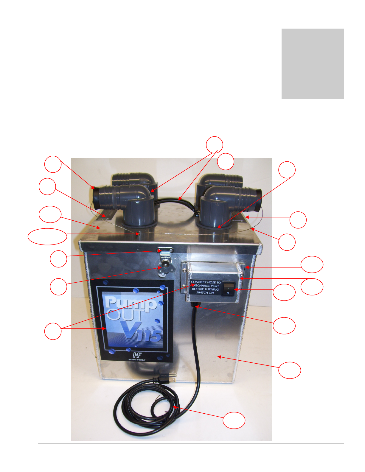
Parts
Section
3
1 2
4 3 5
7 8 9
9
10 11
12
13
9
14
15
16
Replacement parts available for repair of your V115 Pump-out.
6 & 6A
14
Page 15

PARTS SHOWN ON PAGE #14
PART #p DESCRIPTION
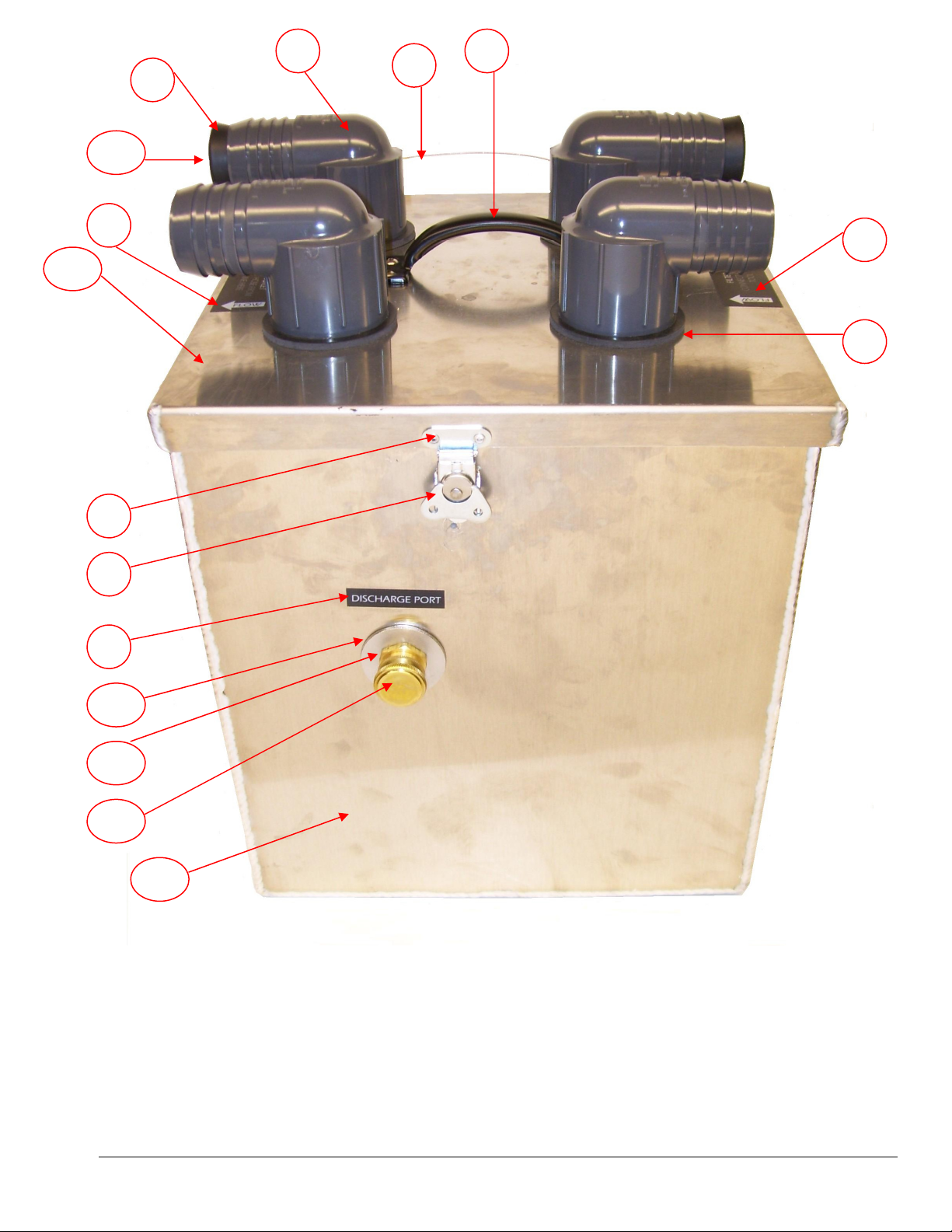
1 PHY052-222 ELBOW 90° 2” FPT X 2” BARB (QTY 4)
NS PHY052-219 ADAPTER 2” MPT X 2” SLIP PVC (QTY 4)
2 PHY106-028 PLUG VAC STOPPER (QTY 2)
2A NM4263 SCREW TEK #10 X 5/8” SS (QTY 2)
3 NA041 HANDLE (QTY 1)
NS NM4061 SCREW 10-32 X 1/2” SS BHCS (4 for Handle)
NS NM4081 NUT 10-32 HEX NYLOCK SS (4 for Handle)
4 PHY052-015 GASKET ADAPTER ELBOW (QTY 4)
5 NM4460 CABLE - Sold per foot (QTY 2.5 ft)
NS NM4462 CABLE CRIMPS (QTY 3)
6 NM4061 SCREW 10-32 X 1/2” SS BHCS (1 for Cable)
6A NM4081 NUT 10-32 HEX NYLOCK SS (1 for Cable)
7 NS121 LATCH HOOK (QTY 2)
8 NS120 LATCH (QTY 2)
NS NS116 RIVETS 1/8” (QTY 8)
9 LAC12H LABEL SET – 5 PIECES
10
NM5714
ROCKER SWITCH – DPST (QTY 1)
11 NM5051 STRAIN RELIEF 3/8” MPT (QTY 3)
NS NM5239B NUT STRAIN RELIEF 3/8” FPT (QTY 3)
13
14
NS
NM4456
NM4464
GASKET SWITCH BOX (QTY 1)
PUMP OUT TANK – ALUMINUM (QTY 1)
1” X 4” ADHESIVE PADS (QTY 6)
15 SWITCH BOX – ALUMINUM (QTY 1)
16
NS
NS
PP05-008002
PUMP OUT LID – ALUMINUM (QTY 1)
GASKET – Sold per Foot (QTY 5.25 ft)
ADHESIVE FOR LID GASKET – 10.3 fl oz
15
Page 16
16 7 8
9 17 18 19
9 1 3 5 9 2
4
2A
14
16
Page 17

PARTS SHOWN ON PAGE #16
PART # DESCRIPTION
1 PHY052-222 ELBOW 90° 2” FPT X 2” BARB PVC (QTY 4)
NS PHY052-219 ADAPTER 2” MPT X 2” SLIP PVC (QTY 4)
2 PHY106-028 PLUG VAC STOPPER (QTY 2)
2A NM4263 SCREW TEK #10 X 5/8” SS (QTY 2)
3 NA041 HANDLE (QTY 1)
NS NM4061 SCREW 10-32 X 1/2” SS BHCS (4 for Handle)
NS NM4081 NUT 10-32 HEX NYLOCK SS (4 for Handle)
4 PHY052-015 GASKET ADAPTER ELBOW (QTY 4)
5 NM4460 CABLE - Sold per foot (QTY 2.5 ft)
NS NM4462 CABLE CRIMPS (QTY 3)
7 NS121 LATCH HOOK (QTY 2)
8 NS120 LATCH (QTY 2)
NS NS116 RIVETS 1/8” (QTY 8)
9 LAC12H LABEL SET – 5 PIECES
14 PUMP OUT TANK – ALUMINUM (QTY 1)
NS NM4464 1” X 4” ADHESIVE PADS (QTY 6)
15 SWITCH BOX – ALUMINUM (QTY 1)
16 PUMP OUT LID – ALUMINUM (QTY 1)
NS GASKET – Sold per Foot (QTY 5.25 ft)
NS PP05-008002 ADHESIVE FOR LID GASKET – 10.3 fl oz
17 NM4264 WASHER 2” X 1” SS (QTY 1)
18 BR319 ADAPTER MGH X 3/4” MPT (QTY 1)
19 BR325 CAP GARDEN HOSE (QTY 1)
NS BR600 RUBBER WASHER (QTY 1)
17
Page 18
14
20 21 22
11
23
24 25
PARTS SHOWN ON PAGE #18
PART # DESCRIPTION
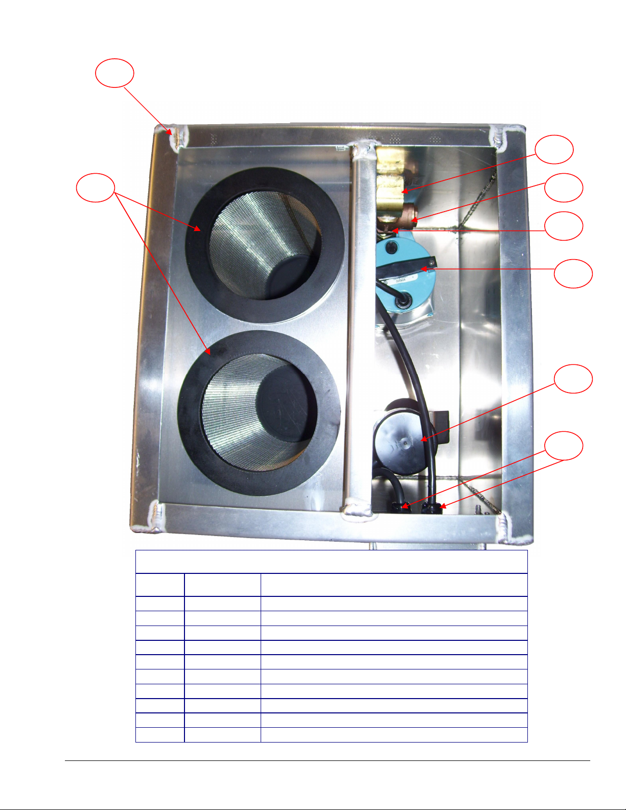
11 NM5051 STRAIN RELIEF 3/8” MPT (QTY 3)
NS NM5239B NUT STRAIN RELIEF 3/8” FPT (QTY 3)
14 PUMP OUT TANK – ALUMINUM (QTY 1)
NS NM4464 1” X 4” ADHESIVE PADS (QTY 6)
20 AC11S SS FILTER SCREEN (QTY 2)
21 NM5053 PUMP OUT PUMP (QTY 1)
22 NM5054 FLOAT SWITCH ASSEMBLY (QTY 1)
23 NM5094 ELBOW 90° 3/4” STREET (QTY 1)
24 NM5052 CHECK VALVE 3/4” FPT (QTY 1)
25 BR078 NIPPLE 3/4” HEX (QTY 1)
18
Page 19

Section
4
Limited Warranty
Your V115 Pump-out is designed to give you years of reliable service. If a problem should arise use the
troubleshooting section in the operation manual to diagnose and correct the problem if possible.
If you are unable to determine the cause or solution to the problem contact your distributor or Hydro-Force
for assistance.
All components of the V115 Pump-out are warranted to be free of defects in material and workmanship for
one year from the date of purchase.
During the warranty period, Hydro-Force will, at its option repair or replace components which prove to be
defective. This warranty does not provide for replacement of complete units due to defective components.
Any costs for transportation or related service labor are not covered in this warranty. Replacement parts are
warranted only for the remainder of the original warranty period.
This warranty shall not apply to defects resulting from improper operation, lack of maintenance,
unauthorized modification, chemical incompatibility, misuse, abuse or exposure to freezing temperature
conditions. It does not cover normal wear items such as filter screens, hoses, cords or other items which
require replacement as a result of ordinary usage.
To obtain warranty service for the V115 Pump-out, contact your distributor or Hydro-Force. If the unit must
be returned to Hydro-Force or an authorized service center, the purchaser shall prepay shipping charges for
products returned for warranty service. No returned items will be accepted by Hydro-Force without prior
authorization. All returns must have a return authorization number, issued by Hydro-Force, clearly marked on
the exterior of the package.
Hydro-Force makes no other warranty either expressed or implied with respect to this product.
The remedies provided herein are the purchaser’s sole and exclusive remedies. In no event shall Hydro-Force
be liable for any direct, indirect, special, incidental or consequential damages.
This warranty gives you specific legal rights. You may also have other rights which vary from jurisdiction to
jurisdiction.
19
 Loading...