

Page 1

Copyright © 2005 by Hydro-Force
LIMITED WARRANTY
Your Omni-Pro Sprayer is designed to give you years of reliable service. If
a problem should arise, use the troubleshooting section in the operation
manual to diagnose and correct the problem if possible.
If you are unable to determine the cause or solution to the problem,
contact your distributor or Hydro-Force for assistance.
Hydro-Force warrants the Omni-Pro Sprayer to be free of defects in
material and workmanship. This warranty shall extend for one year from
the date of purchase.
During the warranty period, Hydro-Force will, at its option, repair or
replace components which prove to be defective. This warranty does not
provide for replacement of complete units due to defective components.
Any costs for transportation or related service labor are not covered in this
warranty. Replacement parts are warranted only for the remainder of the
original warranty period.
This warranty shall not apply to defects resulting from improper operation,
lack of maintenance, unauthorized modification, chemical incompatibility,
misuse, abuse, or exposure to freezing temperature conditions. It does
not cover normal wear items such as o-rings, valve seals, pump seals,
hoses, jets, cords, batteries, chemical bottles, or other items which require
replacement as a result of ordinary usage.
To obtain warranty service for the Omni-Pro Sprayer, contact your
distributor or Hydro-Force. If the sprayer must be returned to HydroForce or an authorized service center, the purchaser shall prepay shipping
charges for products returned for warranty service. All returns must have
a Return Authorization number, issued by Hydro-Force, clearly marked on
the exterior of the package. No returned items will be accepted by HydroForce without prior authorization.
Hydro-Force makes no other warranty, either expressed or implied, with
respect to this product.
The remedies provided herein are the purchaser’s sole and exclusive
remedies. In no event shall Hydro-Force be liable for any direct, indirect,
special, incidental, or consequential damages.
This warranty gives you specific legal rights. You may also have other rights
which vary from jurisdiction to jurisdiction.
12 Volt Sprayer
Page 2

Table of Contents
Feature and Benets .......................................... 3
Specications .....................................................3
Complete Sprayer Diagram ..............................4
Complete Sprayer Parts List ..............................5
Sprayer Body and Gun Diagram .......................6
Sprayer Body and Gun Parts List ......................7
Sprayer Base Diagram .......................................8
Sprayer Base Parts List ......................................9
Wiring - Omni Pro AS75 .................................10
Omni Pro Chargers .........................................11
Safety and General Maintenance ....................12
Charging ................................................. 12 & 13
Operation ........................................................13
Troubleshooting ..............................................14
Warranty Information .....................................16
Notes
15
Page 3

Wide Bottom: prevents the sprayer from tipping over
Translucent Bottle: make it easy to see the level of chemical
2 1/2 Gallon Bottle: the sprayer holds more chemical, allowing less
frequent relling.
Removable Bottle: allows for quick chemical switching
Large cap: enables easy rells and less chance of spills
15 Feet of Coiled Hose: Prespray upholstery with sprayer in one position
Built In Extension Holder: Keep out of the way on truck
Large Wheels: Easy movement on commercial jobs or large rooms
Extendable Handle: for easy transportation and movement
Extra Jets Easily Attached: move from carpet prespray to upholstery
prespray to protector with dierent jets
Easy Priming and Rinsing of Lines: removable jets
Easy to Recharge: cigarette lighter to battery to outlet; charges overnight
using a “live” accessory outlet. Plug in to “top-o” charge between jobs.
Also available:
• Optional 110v recharger (Hydro-Force part # NM4108).
• Continuously powered 12 volt accessory adapter (Hydro-Force part #
NM4118)
See “Charging” section for specics.
Length of Charge: sprays up to 60 gallons on full charge
Easy to Fix: remove 6 screws to service pump or battery
Sealed Cavity: pump and battery protected from spills
Flojet Water Pump: durable, easy to maintain, self-priming
Rotomolded Plastic: proven to last for years
Features and Benets
Hose
Length: 15’
Diameter: 3/8”
Charger
Battery
Sealed, Rechargable
Volts: 12.0
Amperage: 7.0
Fuse
Amps: 10
Specications
Pump
Flow: 1 gallon/minute
Pressure: 50 psi
Voltage: 12 VDC
Amperage: 4.0
Jets
Pre-spray:
Veejet, Hydro-Force
part # B281, size = 8005
Protectant:
Teejet, Hydro-Force
part # B006, size = 6501
Troubleshooting
Pump not turning
on - No power
Battery not
charging
Not spraying
properly
Solution dripping
from jet with
valve closed
Problem Cause Solution
Battery not charged
Fuse Blown
Battery faulty
Faulty switches or internal wiring
Pump motor faulty
Pump seized
Recharge battery - (see Charging)
Check fuses - Replace as needed
Replace battery
Check wiring & test switches - repair
as needed
Replace pump motor
Repair or replace pump head &
bearing - Check motor
Failure to follow Charging
instructions
Power source out
Fuse blown
Battery faulty
Charger faulty
Faulty internal wiring
Review Charging section
Check fuses - Replace as needed
Find a different power source
Replace fuse & check for shorts
Replace battery
Replace charger & check fuse
Check wiring - Repair as needed
Jet clogged
Jet worn
Chemical hose not submerged
in jug
Chemcial filter clogged (intake)
Air leak in chemical hose (intake)
Chemical hose restricted (intake)
Chemical jug not vented
Spray hose restricted (outlet)
Spray valve faulty
Debris in pump head
Pump faulty
Battery not charged
Battery faulty
Faulty switches or internal wiring
Chemcial to thick to pump
properly
Clean or replace jet
Replace jet
Make sure end of chemical hose
with filter is in the chemical
Clean or replace filter
Repair or replace hose
Un-kink, clean out or replace hose
Remove cap - enlarge hole in cap
for hose
Un-kink, clean out or replace hose
Repair or replace valve
Clean out pump head - Replace
valves as needed
Repair or replace pump
Recharge battery
Replace battery
Check wiring & test switches
Charge chemicals - Must be similar
in viscosity to water
Spray valve faulty
Check valve faulty
Jet worn
Extension faulty
Rapair or replace valve
Replace check valve
Replace jet
Replace extension
314
Page 4
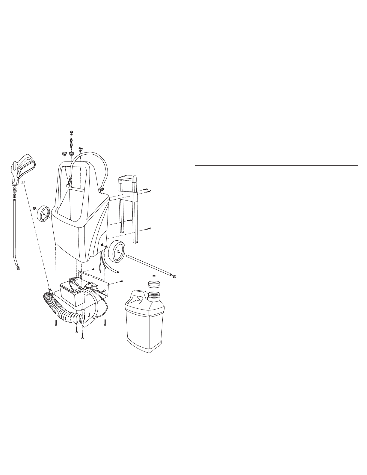
Complete Sprayer Diagram
*lid is included
Unused batteries can lose their charge . Test the sprayer before using on
a job to ensure that the battery is charged. See the “Charging” section for
instructions on how to charge the battery.
1. Fill chemical container with desired chemical and place container in
the OmniPro Sprayer.
2. Place the chemical feed hose into the chemical container and secure
the cap.
3. Turn the switch to the ON position and spray into a container until
pump is primed. Turn the switch to the OFF position.
(Properly dispose of the sprayed chemical.)
4. Place the proper size jet on the spray gun for the present application.
5. Move the sprayer to the location where the sprayer is to be used.
6. Turn the switch to the ON position and spray chemical as needed.
7. When the job is completed, turn the switch to the OFF position.
8. Return the sprayer to your van.
9. Remove the chemical feed hose from the chemical container and
replace the solid cap for storage.
10. Place the chemical feed hose into a container filled with water.
11. Turn the switch to the ON position and spray into a container until
the chemical is flushed out of the pump and hoses.
(Properly dispose of the sprayed chemical and water.)
12. Turn the switch to the OFF position and return the sprayer to its storage spot in your van.
13. Connect the charger to the sprayer and plug the charger into the van
power source.
Operation
• The optional 110 volt wall charger (Hydro-Force part # NM4108) can be
used for a maximum of 12 hours. Overheating of the battery will occur
with longer charges, with the result being reduced battery life (or, with
extreme cases, battery failure.)
We are 100% confident that, by following these procedures, users will find
the Omni Pro to be the most reliable and durable sprayer available.
Charging (continued)
134
Page 5

PART # DESCRIPTION QUANTITY
AP21 Water Pump 1
NM4100 Battery 1
NM5082 Coil Hose 15 feet
NA030 Spray Gun Valve 1
NA0833 Extension 1
B281 Veejet 8005 ¼” FPT 1
NM4102 Bottle 1
NM4103 Cap 1
NA0840 Strainer 1
NA0839 Barb Nylon 1
XAF1 Tubing ¼” ID 48”
BR013 Barb 1/4Fx1/4 1
NM4104 Axle Cap 2
NM4105 Wheel 1
NM4107 Handle Extendable 1
NM4106 Base Plate 1
NS123 Hose Clamps 2
NS162 Elbow Barbs 2
NS126 Power Recepticle 1
NM4111 Switch Rocker 1
NM4017 Connectors 4
NM4020 Wire Black 2 feet
NM5020 Wire Red 2 feet
NM4110 Axle 1
NM4113 Molded Plastic 1
BR335 Quick Male 2
BR337 Quick Female 1
B006 Upholstery TeeJet 6501 1
NM4116 Rubber Bushing 3/8” 3
NM4061 Base Plate Screws 10
NM4080 Handle Screws 2
BR112 Coupling ¼” FXF 1
NM5034 Pump Base Bolts 2
NM4003 Pump Base Nuts 2
NM5066 Pump Base Washers 2
NA0802 Strainer Body 1
NA0803 Strainer 1
NA0826 Teejet Cap 1
NM4074 Double Stick Tape 4 inches
NM4109A Car Charger (included) 1
NM4108A Wall Charger (not included) optional
NM4117 Rubber Bushing 3/4” 2
NM4064 Washer Spacer 2
PLF-AGC10 Fuse 1
NS177 Fuse Casing 1
NM4118 Car Charger Adapter w/ Aligator Clips optional
PKGA10 Diode 1
Complete List of Parts
• Run fresh water through the sprayer after each day of use to flush
chemical from the pump and hoses.
• Keep chemical containers and strainer screen clean.
• Keep charger connected to sprayer and plugged into to van power
supply when not in use to maintain fully charged battery. See
Charging section for details.
• While sprayer and pump are made with chemical resistant materials,
and can handle a wide range of chemicals, do not assume chemical
compatibility.
• Contact your distributor or the manfacturer if you have questions
regarding your chemicals compatibility.
• No warranty, expressed or implied, can be considered where
component failure is caused by chemical effects.
• Label all containers to properly identify chemicals.
• Do not use to spray liquids with temperatures above 160°F. (71°C)
• Do not use to spray flammable or combustable liquids.
• Do not use sprayer where flammable vapors are present.
• Pump can run dry without damage.
• If stored in possible freezing conditions the sprayer must be liquid free
or winterized with anti-freezing chemical.
• Do not operate without inlet strainer.
The Omni-Pro Sprayer is the strongest, best-built 12 volt sprayer on the
market. With proper use, the Omni-Pro’s robust “non-memory” battery
and charging system will give long, reliable service.
The following facts apply to ANY 12-volt charging device (cell phones,
ipods, and sprayers included):
• The 12 volt vehicle accessory outlet charger is a “trickle” charger and
takes 10 or more hours to fully charge a discharged battery. The vehicle charger can “top-off” the battery between jobs.
• The vehicle’s accessory/lighter outlet MUST be “live” in order for the
charger to do its job. Many accessory outlets are NOT powered when
the vehicle’s ignition is “off”.
• If the accessory/cigarette plug is NOT powered when the ignition is
“off”, an accessory outlet with alligator clip ends is available (HydroForce part # NM4118). This cord can be attached directly to the terminals of a truckmount or van battery, and will enable the charger to be
“on” and constantly charging the battery.
Safety and General Maintenance
Charging
512
Page 6
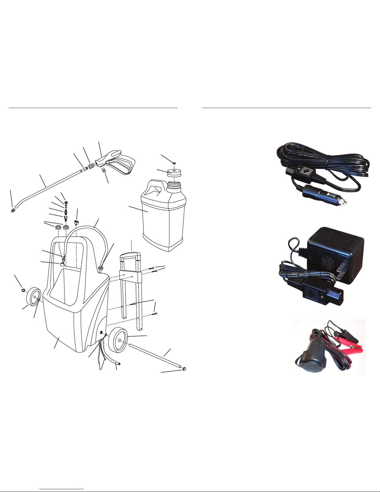
Sprayer Body and Gun Diagram
A
B
C
D
E
F
A
B
C
A
B
C
D
E
F
G
H
I
J
K
L
K
G
I
M
N
O
P
Q
R
S
T
B
OmniPro Battery Chargers
NM4109A
Car Charger 12 Volt
Cigarette Lighter Plug
(Included with Omni Pro
Sprayer)
NM4108A
Charger 110 Volt
Wall Plug
(Optional Accessory)
NM4118
Adapter w/ Alligator Clips
For Cigarette Lighter Plug
(Optional Accessory)
116
Page 7
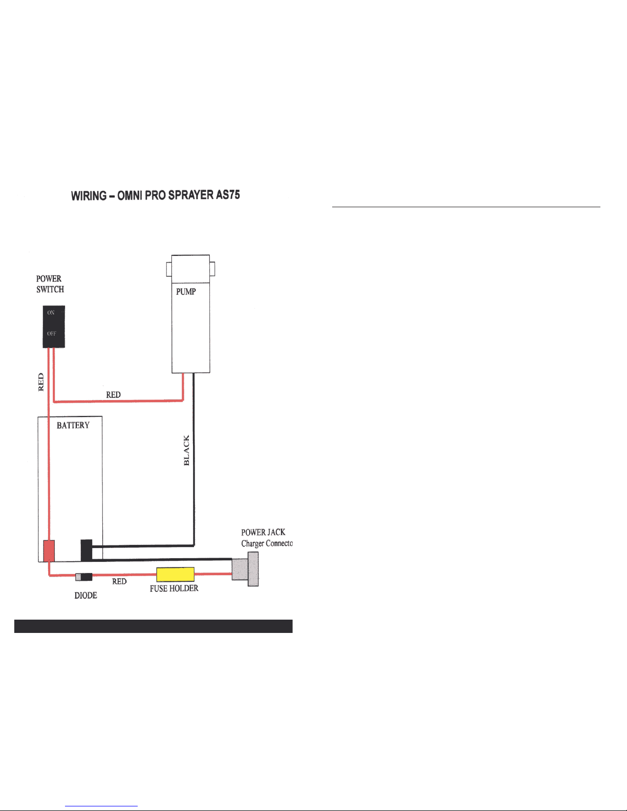
NUMBER PART # DESCRIPTION QUANTITY
Gun Diagram
A B281 Veejet 8005 ¼” FPT 1
B NA0833 Extension 1
C BR335 Quick Connect Male 1
D BR337 Quick Connect Female 1
E NA030 Spray Gun - Valve 1
F BR112 Coupling ¼” FXF 1
Bottle Diagram
A NM4116 Rubber Bushings 1
B NM4103 Cap 1
C NM4101 Bottle with Lid 1
Sprayer Body Diagram
A NM4111 Switch Rocker 1
B XAF1 Tubing 48”
C NM4116 Rubber Bushings 3/8” 3
D NM4107 Handle Extendable 1
E NM4061 Base Plate Screws 10
F NM4080 Handle Screws 2
G NM4105 Wheel 2
H NM4110 Axle 1
I NM4104 Axle Cap 2
J NM5020 Wire Red 2 feet
K NM4064 Washer Spacer 4
L NM4113 Molded Plastic 1
M NA0840 Strainer 1
N NA0839 Barb Nylon 1
O NM4117 Rubber Bushing 3/4” 2
P BR335 Quick Connect Male 1
Q NA0802 Strainer Body 1
R NA0803 Strainer 1
S B006 Upholstery TeeJet 6501 1
T NA0826 Teejet Cap 1
710
Page 8
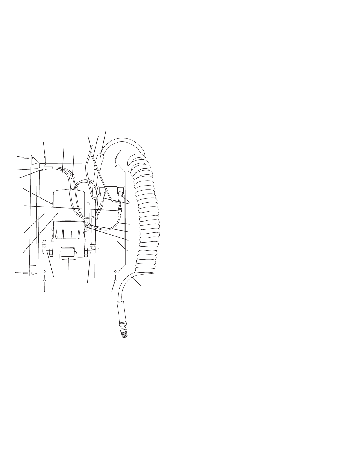
Sprayer Base Diagram
Back of Sprayer
A
A
B
C
D
E
F
A
D
G
H
I
A
K
L
M
L
A
A
P
Q
N
O
J
R
S
T
NUMBER PART # DESCRIPTION QUANTITY
A NM4061 Base Plate Screws 10
B NM4106 Base Plate 1
C NM5049 Splicer Wire - Yellow 4 inches
D NM5020 Wire Red 2 feet
E NS144 Tube Black PVC 1/2 IDX 5/8 OD 5 inches
F NM4017 Connectors 4
G NM5066 Pump Base Washers 2
H NM4003 Pump Base Nuts 2
I NM4100 Battery 1
J NM5082 Coil Hose 15 feet
K NS123 Hose Clamps 3/8” 2
L NS162 Elbow Barbs 2
M AP21 Water Pump 1
N NM4020 Wire Black 2 feet
O NM4011 Heat Shrink Tube 3/8 1 inch
P NS126 Power Recepticle 1
Q NM5034 Pump Base Bolts 2
R NM4074 Double Stick Tape 4 inches
PLF-AGC10 Fuse 10 amp (not shown) 1
S NS177 Fuse Casing 1
T PKGA10 Diode 1
98
 Loading...