

Page 1
1
Extractor
Hydro
-
Force
R
evised:
10-08-2014
Operating Manual
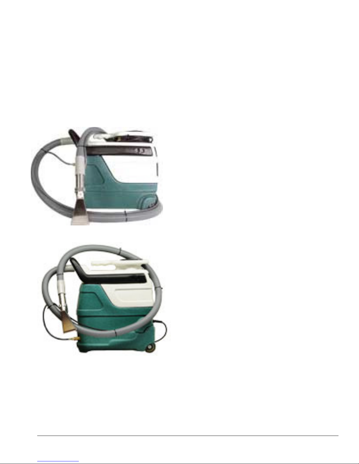
Power X Pro Spot
MA51
Power X Pro Spot
Extractor
MA51H
Power X Pro Spot
Extractor with Heat
4282 South 590 West
Salt Lake City, UT 84123
801-268-2673
801-268-3856 FAX
Page 2

2
Power X Pro Spot Extractor Operating Manual
TABLE OF CONTENTS
TOPIC PAGE #
• Introduction 3
• Technical Specifications 4
SECTION 1: Operational Safety
• Electrical Safety 5
• Mechanical Safety 6
SECTION 2: Operation Procedures
• Electrical Supply 7
• Water Supply & Chemicals 7
• Solution & Vacuum Hoses 7
• Starting System - Switches 8
• Shutdown Procedures 9
• Troubleshooting 10-11
• Solution Flow Path MA51 12
• Solution Flow Path MA51H 13
• Wiring Diagrams MA51 14
• Wiring Diagrams MA51H 16
SECTION 3: Maintenance/ Technical
• Maintenance 18
• Parts 21
o MA51 22
o MA51H 27
o Hoses & Tool 34
• Warranty 35
Page 3

3
Introduction
Congratulations on your purchase of the Hydro-Force Power X Pro Spot
Extractor. The Power X Pro Spot Extractor is designed to combine versatility
with ease of transport. Years of experience, engineering, and planning have gone
into the design and manufacturing of the Power X Pro Spot Extractor. We take a
great deal of pride in the Power X Pro Spot Extractor; our goal is no less than
your complete satisfaction.
This manual will provide users with the knowledge required to operate the Power
X Pro Spot Extractor safely, to understand how to properly operate and maintain
the machine, and to ensure that the equipment operates at its maximum
performance level.
All users must read and understand this manual completely before
operating the machine.
Always maintain this manual in legible condition adjacent to the Power X Pro
Spot Extractor, or place in a secure location for future reference.
Any questions pertaining to the operating or servicing of this unit should be
directed to your nearest Hydro-Force distributor.
This manual is written specifically for the Power X Pro Spot Extractor units
manufactured by:
Hydro-Force
4282 South 590 West
Salt Lake City, UT 84123
801-268-2673
801-268-3856 FAX
Information in this manual is subject to change without notice and does not
represent a commitment on the part of Hydro-Force or its parent or affiliated
companies.
Page 4

4
Technical Specifications
Power X Pro Spot Extractor Model MA51
Height: 19”
Length: 21”
Width: 10”
Weight: 18lbs.
Solution Tank Capacity: 3 gallon
Recovery Tank Capacity: 3 gallon
Power Cord: 20 foot – 16/3
Solution Outlet 1/4” Male Quick Connect
Solution Pump: Flojet ET508224-HP pump
55 psi – 0.37gpm
Vacuum Motor: AMETEK Lamb 4.8” Diameter – Peripheral discharge
Two Stage 87.7cfm – 76.5” WC
Power Draw: 6.42 / 7.3 amps
Power X Pro Spot Extractor with Heater Model MA51H
Height: 24”
Length: 21”
Width: 10”
Weight: 30lbs.
Solution Tank Capacity: 3 gallon
Recovery Tank Capacity: 3 gallon
Power Cord: 20 foot 16/3
Solution Outlet 1/4” Male Quick Connect
Solution Pump: Flojet ET508224-HP pump
55 psi – 0.37gpm
Vacuum Motor: AMETEK Lamb 4.8” Diameter – Peripheral discharge
Two Stage 87.7cfm – 76.5” WC
Heater: 600 Watt
Power Draw: 11.7 / 12.3 amps
Standard Equipment
Tool: PA205 - Stainless Steel 3.5” Detail Tool
Vacuum Hose: 7’ X 1-1/4” with 1-1/2” cuffs
HP Solution Hose: 8’ x 3/16” with 1/4” female quick connect
Page 5
5
Safety
Section
1
CAUTION! This machine is an electrical appliance. Care must be
taken to reduce the risk of electrical shock.
• READ AND UNDERSTAND ALL INSTRUCTIONS BEFORE OPERATING THE POWER X
PRO SPOT EXTRACTOR.
• To reduce the risk of property damage or injury, repairs to electrical systems should only be performed by
experienced technicians. Contact your distributor for assistance. Unplug machine power cord from outlet
before performing any repairs on the extractor.
• This machine shall be grounded while in use to protect the operator from electric shock. The machine is
provided with a three-conductor cord and a three-contact grounding type attachment plug to fit the
proper grounding type receptacle. The green (or green and yellow) conductor in the cord is the grounding
wire. Never connect this wire to other than the grounding pin of the attachment plug.
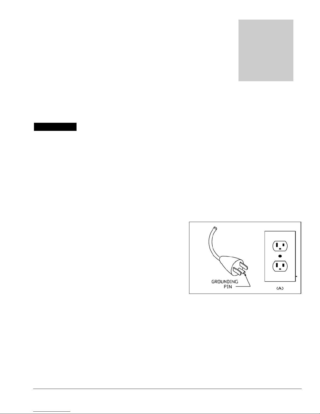
• This machine is for use on a nominal 120-volt circuit and
has a grounding plug that resembles the plug illustrated in
the sketch to the right. Make sure that the machine is
connected to an outlet having the same configuration as
the plug. No plug adapter should be used with this
machine.
• The power cord supplied with this machine is properly
sized to handle the electrical load of this machine and
properly grounded as described above. Any extension
cords used with this machine must be similarly sized and
grounded to assure safe operation. A properly sized
GFCI protected cord can be used for additional protection.
• Do not use the POWER X PRO SPOT EXTRACTOR outdoors, in standing water or on wet surfaces. Do
not store the POWER X PRO SPOT EXTRACTOR in wet conditions. If extractor is leaking, unplug machine
power cords from outlets before approaching or touching machine.
• Do not unplug power cord by pulling on the cord. Grasp the plug end when unplugging the cord. Do not pull
the extractor by the cord. If cord or plug is damaged, do not use cord. Replace with new cord or repair as
needed before use.
• Overloaded circuit may not always trip circuit breaker. Reduced voltage to machine on overloaded circuit will
prevent components from operating properly.
Page 6

6
WARNING! This machine must be protected from conditions which may
damage the pump, tank, hoses and other components.
• Freezing of water in this machine will cause serious damage. The POWER X PRO SPOT
EXTRACTOR, solution hoses, and tools must be protected from freezing temperature. Store, transport, and
use this equipment only in temperatures well above freezing. (32ºF or 0ºC). If you suspect the POWER X
PRO SPOT EXTRACTOR has been frozen, do not plug in or turn on machine until you are sure it has thawed
completely.
• If the equipment cannot be stored or transported in a warm environment, it can be guarded from freezing by
running an anti-freeze solution through the incoming water lines, chemical feed system, solution pump, solution
lines, tools and pump-out pump. The machine is filled at the factory with anti-freeze to eliminate damage during
shipment in cold weather.
o The anti-freeze solution must be completely flushed from the machine before it is returned to service.
• The POWER X PRO SPOT EXTRACTOR must not be used to pick up flammable or combustible materials
or used in areas where these materials may be present.
• Solvent-based or water-based solutions containing solvents may damage the pump, hoses, and other
components. Do not assume chemical compatibility. Contact your distributor or Hydro-Force if you have
questions regarding the compatibility of your chemicals with the machine.
• Do not clean with solutions that are at temperatures above 100ºF.
• Rinse the solution tank, chemical system, and pump with fresh water after each day’s use.
• Do not allow pump to run dry. Always maintain adequate solution level to supply solution pump.
• Solution hoses may rupture if worn or damaged. Do not use solution hoses if hose covering is cut, bulging, or
otherwise damaged. Examine solution hoses daily and replace or repair hoses as needed.
• Keep Vacuum Filter Cap clean and check float for proper operation. Do not operate the POWER X PRO
SPOT EXTRACTOR without the Vacuum Filter Cap in place. Use defoamer to eliminate foam build-up
during cleaning and prevent foam/moisture from entering vacuum.
***Use common sense to protect yourself and others while using this equipment.***
• Keep pets and children away from the machine when in use.
• Keep all body parts, hair, and loose clothing away from openings and moving parts. Always wear appropriate
clothing and safety equipment when operating unit.
• Use extra care when cleaning on stairs. Wet carpet on stairs can be slippery.
• Secure latch before moving. Lift using only the appropriate handle.
• Water may be spilled, drip, or be exhausted from vacuums during operation. Place unit in area where water will
not cause damage or use drop cloth to protect surfaces.
Page 7

7
Operation Procedures
Section
2
Knowledge of the proper operation of the Power X Pro Spot Extractor is
required to ensure user safety and efficient performance of the extractor.
Prior to using the Power X Pro Spot Extractor for the first time the Anti-Freeze
used to protect the unit during shipping must be flushed from pump, hoses & tool.
Pour one quart of clean water into the solution tank, connect cord, hoses & tool.
Spray the tool into a bucket or sink to flush out the ant-freeze before using the
Power X Pro Spot Extractor for cleaning.
SET UP AND OPERATION
1. Electrical Cord:
Plug the power cord into the 120volt wall outlet. Make sure the circuit can handle the power load the
operation of the Power X Pro Spot Extractor will place on the circuit.
2. Water Supply & Chemical Mixing– Manual Fill:
• Pour up to 3 gallons of hot water into the solution tank at the front of the machine. This will fill the tank
to a level approximately 4 inches from the top of the tank.
The water temperature should not exceed 120°°°°F.
• Measure and add the appropriate amount of the desired liquid chemical to the water in the solution tank.
The amount of chemical will vary depending on the type of chemical used, the amount of water in the
tank, and the material being cleaned; consult the chemical packaging for specific mixture ratios.
• Powdered chemicals should be dissolved in water in a separate container before being added to the water
in the solution tank.
3. Connection of Hose:
Connect the solution hose to the solution outlet male quick connect on the front of the machine. The other
end of the hose should always be connected to the cleaning tool.
The Vacuum Hose is connected to the barb on the recovery tank of the Power X Pro Spot Extractor. The 11/2” cuff on the vacuum hose is simply pushed onto the barb. The 1-1/2” cuff on other end is connected to
the cleaning tool. Add defoamer to the recovery tank to prevent foam build-up in recovery tank during
cleaning and to keep foam/moisture from entering vacuum.
Page 8

8
4. Starting the Spotter - Power Switches:
MA51
The new style MA51 without heat has two switches, one to turn on the vacuum motor & one to turn on the
solution pump.
(Older Power X Pro Spot Extractors without heat only had one switch for both the vacuum and the pump.)
When you are ready to start cleaning, turn the switches to the ON position. For standard cleaning turn on
both switches. For extraction only, you can turn on just the Vacuum Switch. The FloJet solution pump,
standard on the Power X Pro Spot Extractor is self-priming and usually additional priming procedures are not
required.
If the pump does not prime by itself, or if flow is low or unsteady, check the hose from the solution tank to
the pump and the filter screen for clogging, kinks, or restrictions. Clean or replace hose and/or filter and.
Turn switch ON. Check the valve operation and the jet on the tool for flow restriction that can affect
solution flow.
If you are having trouble with the pump, refer to the trouble shooting guide or contact your distributor for
advice or assistance.
MA51H
The MA51H with heat has three switches one to turn on the vacuum motor, one for the solution pump &
one for the heater.
When you are ready to start cleaning, you should first turn the vacuum switch to the ON position. If you are
extracting only you do not need to turn on the solution pump switch or the heater switch.
If you will be spraying solution, turn the solution pump switch ON. The Flojet solution pump, standard on
the Power X Pro Spot Extractor is self-priming and usually additional priming procedures are not required.
If the pump does not prime by itself, or if flow is low or unsteady, check the hose from the solution tank to
the pump and the filter screen for clogging, kinks, or restrictions. Clean or replace hose and/or filter and.
Turn switch ON. Check the valve operation and the jet on the tool for flow restriction that can affect
solution flow.
If you are having trouble with the pump, refer to the trouble shooting guide or contact your distributor for
advice or assistance.
Once you have solution flow to the tool, you can turn the heater switch ON. Let the heater heat the solution
for about five minutes before you start spraying. For the best heater performance and maximum heat output
use the water slowly and take extra drying passes between spraying passes to give the water more time to heat
up.
5. Spotter Operation:
As you operate the spotter the water and soil you vacuum up will collect in the recovery tank. The Power X
Pro Spot Extractor is equipped with a Float Shutoff assembly which will block the vacuum air flow when the
tank is filled. The float rises with the water level in the recovery tank until it gets to the top, blocking the
vacuum air flow. When this happens you will notice a change in the sound of the vacuum motor. This is your
signal to turn off the unit and empty the recovery tank. Disconnect the hoses and drain the tank by pouring
the water out of the vacuum barb. Do not attempt to drain the recovery tank from the hatch cover opening.
Do not use the same bucket to drain the unit that you use to fill the solution tank. Add more defoamer to the
recovery tank before you resume cleaning.
After draining the tank, before you place the recovery tank back onto the spotter base, check the water level
in the solution tank and add more water and detergent as needed to complete your cleaning. Then place the
recovery tank back onto the solution tank, reconnect the hoses and resume cleaning.
Page 9

9
Shutdown Procedures:
(MA51H only) If you are using the heater turn the heater off before you make the last few cleaning passes
or spray the tool into a bucket for a minute to cool off the heater, before you turn the pump switch off.
When finished cleaning, turn off all switches.
Disconnect the power cord from the outlet.
Disconnect the solution hose and vacuum hose from the Power X Pro Spot Extractor. Pull valve trigger
to release pressure from the hose before disconnecting solution hose.
Drain any remaining water from the solution tank and the recovery tank and dispose in sanitary drain.
Drain the recovery tank by pouring the water out of the vacuum barb. Do not attempt to pour the water
out the recovery tank hatch cover opening. Do not use the same bucket to drain the tank that you use to
fill the tank.
Remove the float shutoff assembly from the recovery tank and clean filter & float as needed.
Replace shutoff assembly and tank lid.
Roll up power cord. Collect and store Power X Pro Spot Extractor, hoses, tool, and any other accessories.
Page 10
Section
2
Problem
Cause
Solution
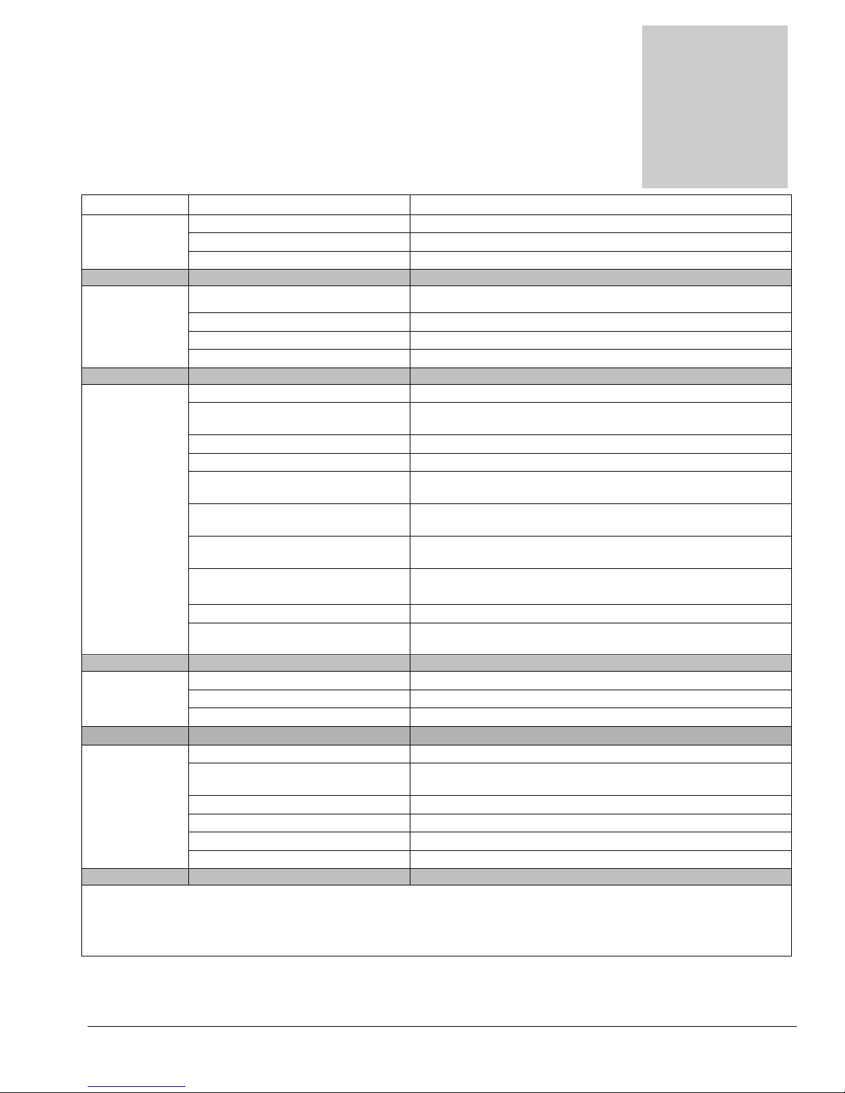
Troubleshooting
Troubleshooting –
Power X Pro Spot Extractor
Machine not Building circuit breaker tripped. Reset breaker or move cord to other outlet
turning on - Faulty power cord Replace cord
No power Faulty switches or internal wiring Check wiring & test switches - Repair as needed *
Solution Building circuit breaker tripped. Reset breaker or move cord to other outlet.
Pump Faulty power cord Replace cord
not running Faulty switches or internal wiring Check wiring & test switches - Repair as needed *
Pump faulty Replace Pump (AP30)
Low Solution Jet too large for pressure desired Check jet size & flow rates use smaller jets
Pressure
and/or Jet worn allowing too much flow Replace jet
Pulsation Solution inlet filter plugged Clean or replace filter
Hose from solution tank restricted Repair or replace hose
Heater Restricted with scale
Solution tank empty Add water to tank - Check & repair auto fill assembly
Pump faulty Repair or replace pump (AP30)
Tool valve faulty Repair or replace valve
Can't connect Pressure in lines Turn off pump - Release pressure
solution hose Quick connects faulty Replace quick connects (AH101B, AH102B)
to machine Wrong style/size quick connects Replace quick connects to match connects on machine
Heater not Faulty switches or internal wiring Check wiring & test switches - Repair as needed *
Heating
(MA51H Only) Temperature Switch tripped Reset manual reset temperature switch.
Faulty temperature switches Replace temperature switches on heater
Faulty Heater Replace heater
Flow too high for proper heating Use smaller jet or slow use of water
Water Starting out too cold Heat water before filling tank – Maximum 120˚F
experienced service technicians.
If you are not experienced in checking electrical wiring contact your nearest authorized service
center to perform tests and repairs to wiring and switches.
(MA51H Only) De-scale or replace the heater
Pressure Relief valve stuck open
(MA51H Only) Replace the pressure relief valve
Pump intake hose or fittings
leaking Repair or replace hose. Tighten clamps or replace fittings
Quick connects or hoses
restricted Clean out or replace quick connects and/or hoses
* To reduce the risk of fire electrical shock or injury repairs to wiring should only be performed by
10
Page 11
Problem
Cause
Solution
Vacuum Building circuit breaker tripped. Reset breaker or move cord to other outlet
Motor Faulty power cord Replace cord
not running Faulty switch or internal wiring Check wiring & test switch - Repair as needed *
Vacuum motor faulty Replace vacuum motor (AV06)
Loss of Vacuum motor faulty Replace vacuum motor (AV06)
Vacuum Vacuum motor gasket damaged Replace gasket (PS10-1030)
Recovery tank lid gasket damaged Replace lid assembly or gasket
Vacuum hose or tool clogged Clean out vacuum hoses and tool
Vacuum hoses or cuffs leaking Replace vacuum hoses, cuffs & connectors as needed
Recovery tank full Drain tank
Float shutoff filter clogged Clean float shutoff filter
Float shutoff stuck Repair or replace float shutoff
Recovery tank damaged Replace recovery tank
Tool won't Jet clogged Clean out or replace jet
spray - low or Inline filter clogged Clean out or replace filter if so equipped
uneven spray Jet worn Replace jet
Jet not aligned properly Re-align jet
Tool valve faulty Repair or replace valve
Quick connects or hoses restricted Clean out or replace quick connects and/or hoses
Pump not pumping See Troubleshooting sections relating to solution pump
* To reduce the risk of fire electrical shock or injury repairs to wiring should only be performed by
experienced service technicians.
If you are not experienced in checking electrical wiring contact your nearest authorized service
center to perform tests and repairs to wiring and switches.
•
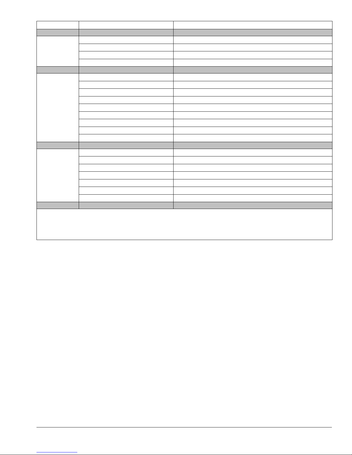
Contact your distributor for additional troubleshooting
assistance, to order parts, or for advice and assistance in
performing necessary repairs.
11
Page 12
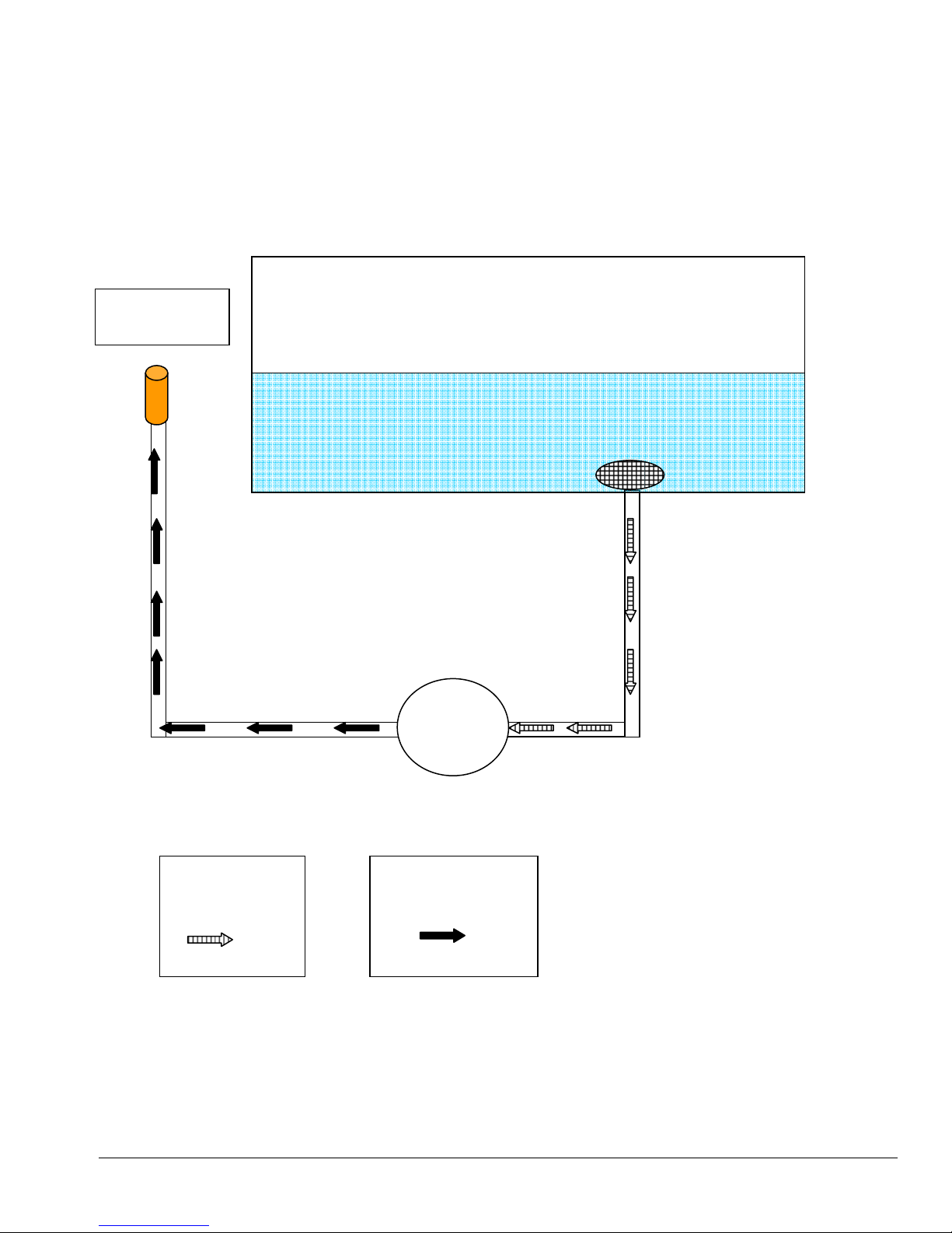
Solution Tank
Pump
MA51
Solution Flow Path
Outlet Quick
Connect
Denotes
incoming water
flow
AP30
Denotes Water
flow in pressure
hose
12
Page 13
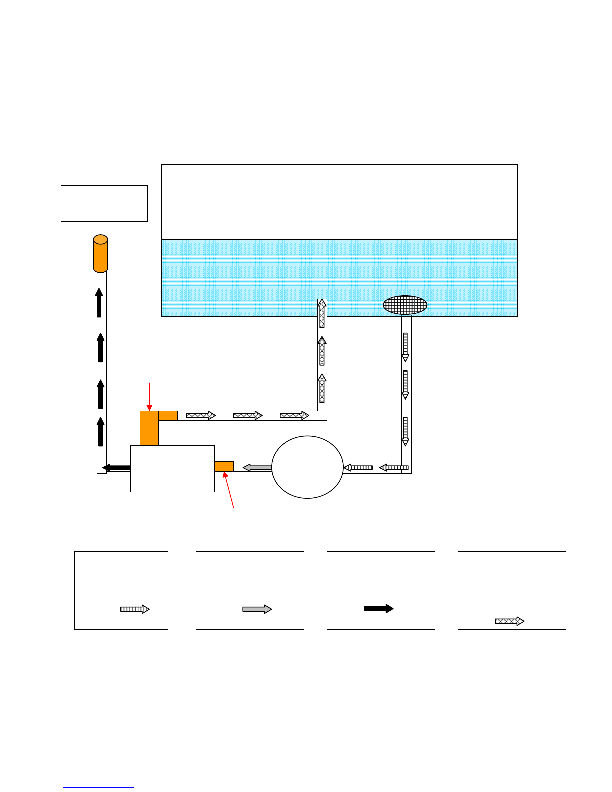
Solution Tank
Pump
HEATER
V
ALVE
CHECK VALVE
MA51H
Solution Flow Path
Outlet Quick
Connect
Denotes
incoming water
flow
PRESSURE
RELIEF
Denotes Cold
Water flow in
pressure hose
AP30
Denotes Heated
Water flow in
pressure hose
13
Denotes Heated
Water by-pass flow
from heater
pressure relief
Page 14
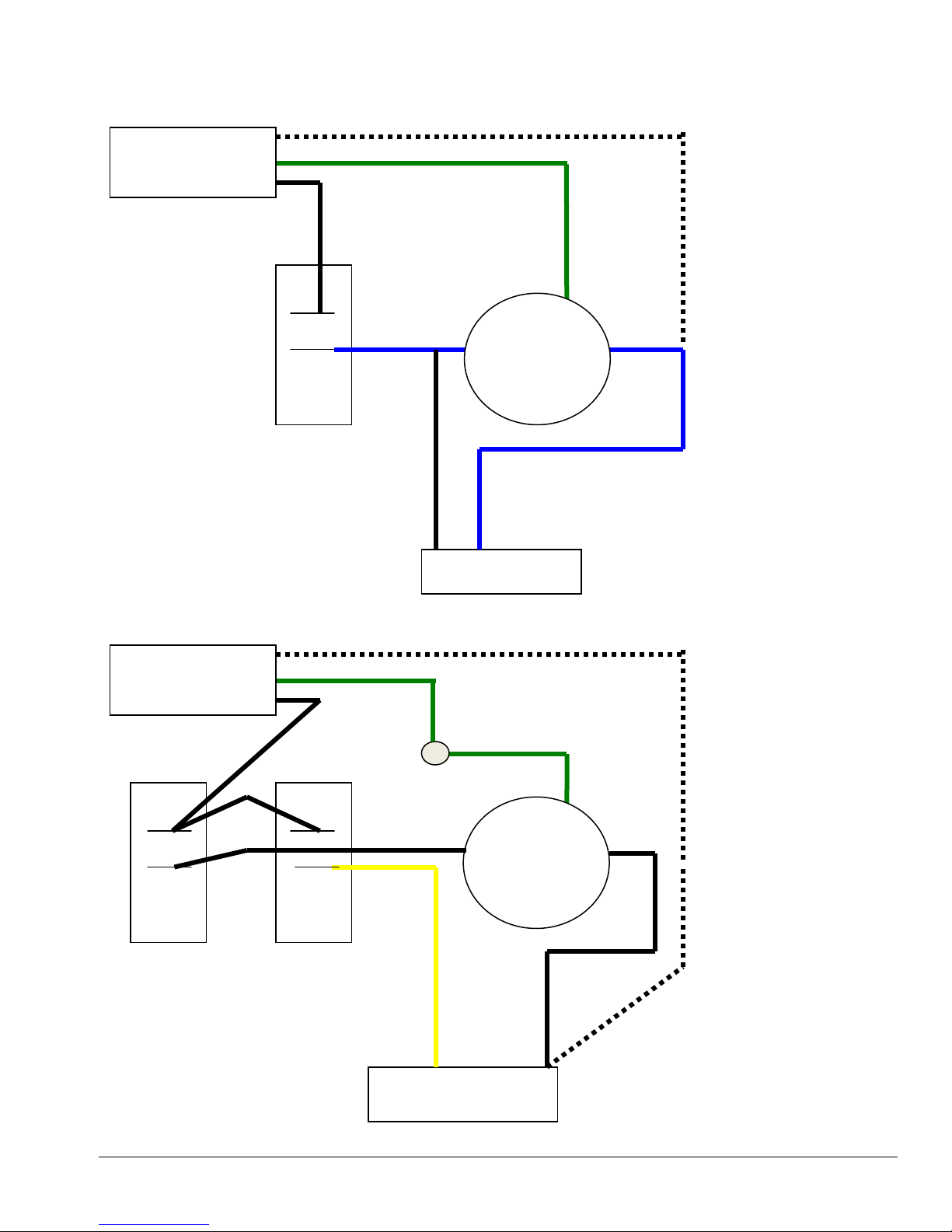
MA51
Wiring Diagram
- Standard
PUMP
YELLOW
WHITE
GREEN
GROUND SCREW
POWER CORD
OLD STYLE
POWER CORD
NEW STYLE
Vacuum
Switch
Power
Switch
Pump
Switch
PUMP
VACUUM
AV06
VACUUM
AV06
14
Page 15
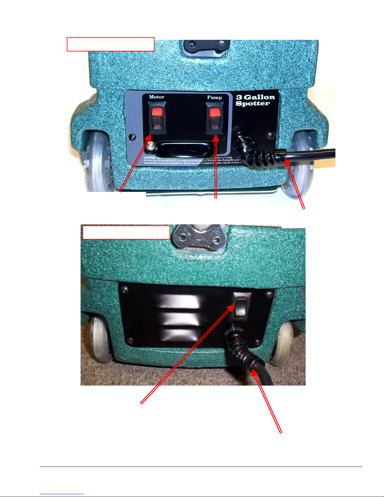
MA51 STANDARD SWITCH PANEL:
Power Cord
New Style – Dual Switch
Vacuum Switch
Solution Pump Switch
Power Cord
Old Style – Single Switch
Solution Pump Switch & Vacuum Switch
When the switch is turned to the ON position
power is supplied to the solution pump motor and
vacuum motor.
15
Page 16
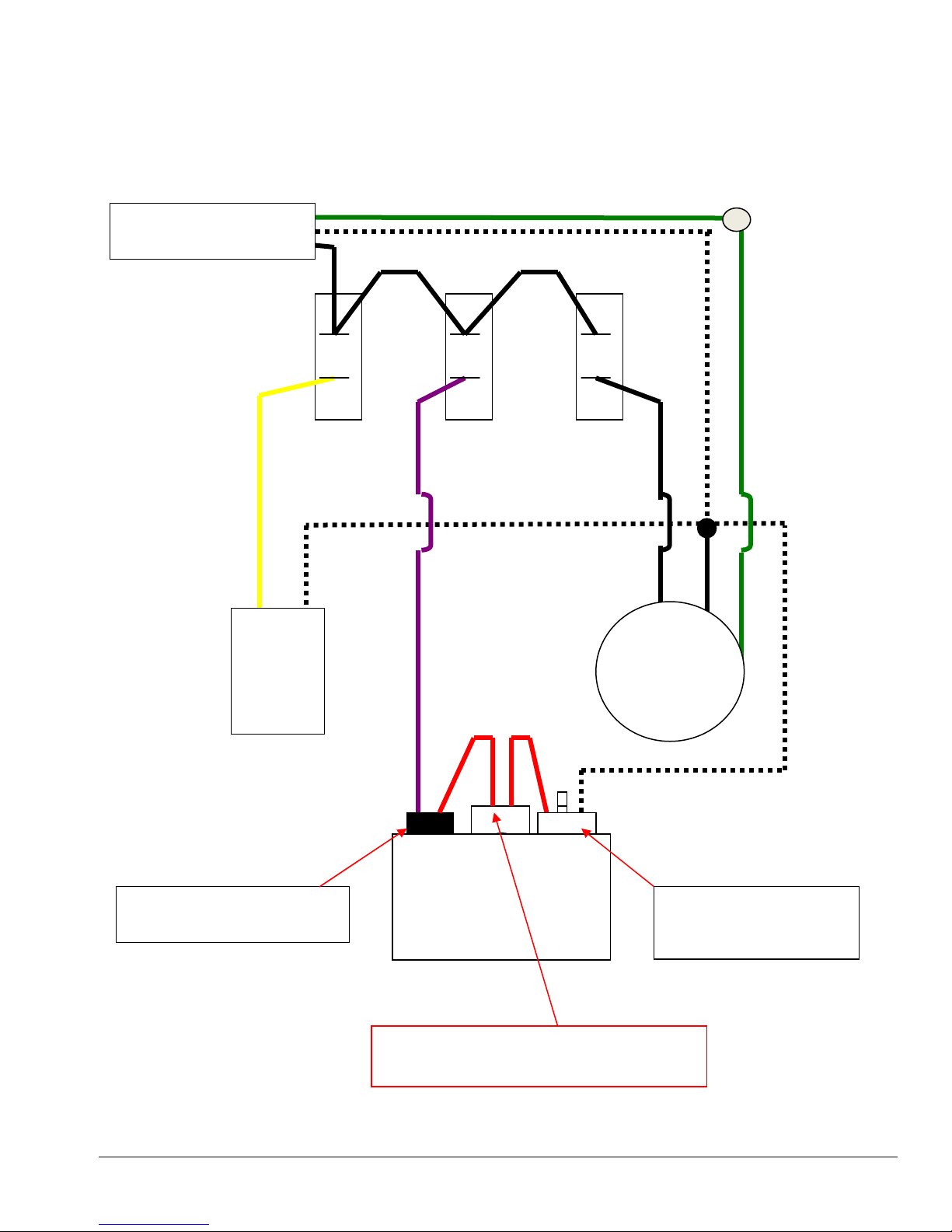
10-0814
-B
GROUND SCREW
MA51H
Wiring Diagram with Heater
POWER CORD
Auto Reset Temperature
PUMP
Control Switch 10-0814
Pump
Switch
Heater
Switch
HEATER
600w
Vacuum
Switch
VACUUM
AV06
Manual Reset Hi-Limit
Temperature Switch
HEATER ELEMENT – PSA101500B
New Style Heater Only
16
Page 17
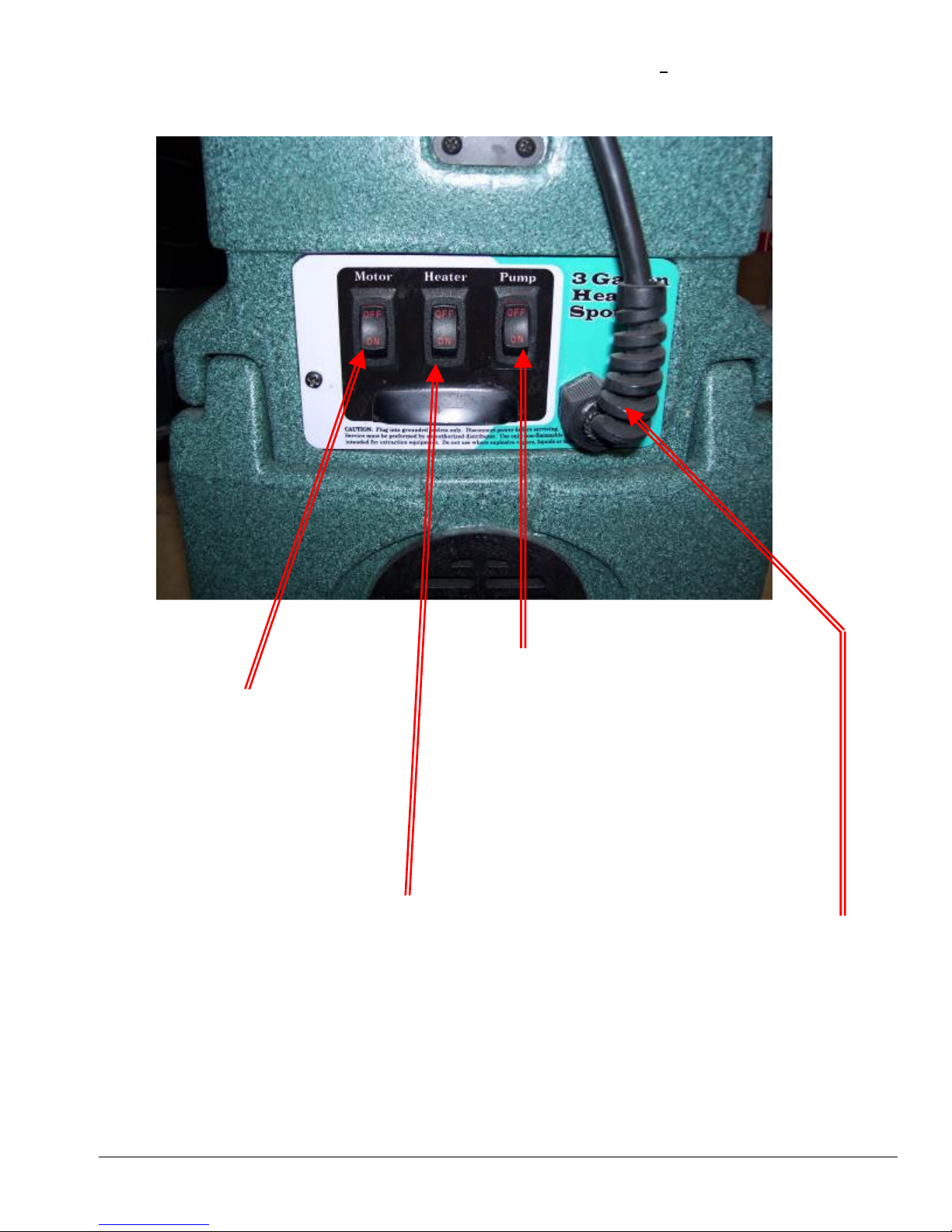
MA51H with HEATER SWITCH PANEL:
Solution Pump Switch
When the switch is turned to the ON position
Vacuum Switch
When the switch is turned to the ON
position power is supplied to the vacuum
motor only.
Heater Switch
When the switch is turned to the ON position power is
supplied to the solution heater only. Always turn pump
switch on first and be sure water is flowing to the tool before
turning heater ON.
Turn heater off and spray tool for a minute to cool off
heater before turning pump off.
When not using solution (Extracting only), do not turn this
switch ON.
power is supplied to the solution pump motor
only.
When not using solution (Extracting only), do not
turn this switch ON.
Power Cord
17
Page 18

Daily
– After Each Job
19
Daily
19
Daily
19
Daily
19
As needed
20
As needed
20
As needed
20
Section
3
Maintenance
Proper maintenance is required to keep the Power X Pro Spot Extractor operating
properly, prevent downtime and to extend the life of your equipment.
WARNING: Disconnect electrical power before performing any service or
maintenance inside machine base or before testing or repairing switches or power
cords. Failure to do so may result in severe personal injury or death.
OPERATION INTERVAL Page #
CLEAN VACUUM SHUTOFF ASSEMBLY
RINSE OUT RECOVERY TANK
FLUSH SOLUTION TANK AND PUMP
CLEAN PUMP-INLET FILTER
DESCALING HEATER – MA51H ONLY
REMOVING BASE TO ACCESS HEATER – MA51H ONLY
STORAGE PREP – FREEZE PROTECTION
18
Page 19

CLEAN VACUUM SHUTOFF ASSEMBLY:
Inside the recovery tank, on top of the stand pipe, is the Vacuum Shutoff Assembly. It functions to prevent
debris and water from being sucked into the vacuum motors. Operating the Power X Pro Spot Extractor
without the Vacuum Shutoff Assembly or with a poorly maintained assembly will greatly decrease the life of
the vacuum motors and will void the warranty.
If debris builds up on this filter, it will reduce the vacuum air flow and may cause a significant decrease in the
rate of water recovery. If debris prevents the float from moving or seating inside the assembly, it may not
stop the airflow when the tank fill with water, and the water will be sucked into the vacuum and blown out
the exhaust. Always use defoamer to prevent foam or moisture from entering vacuums.
To clean:
1. Twist to loosen and pull the assembly off of the stand pipe.
2. Pull fibers and lint off and rinse with clean water.
3. Push the assembly back onto the stand pipe and replace the recovery tank lid.
RINSE OUT RECOVERY TANK:
Clean out the tank on a regular basis to extend the life of vacuum & recovery components as well as keep the
tank smelling better.
1. Remove the recovery tank lid.
2. Use a hose to rinse the dirt and debris out of the recovery tank.
3. Spray the tank with a deodorizer or disinfectant.
4. Replace the recovery tank lid.
5. Dispose of the dirty water and debris.
FLUSH SOLUTION TANK AND PUMP:
1. Pour one gallon of clean water into the solution tank. Slosh the water around in the tank to clean tank
and pour water out and dispose of the dirty water.
2. Pour another gallon of clean water into the tank.
3. With Cord plugged in, connect the solution hose& tool to the solution outlet male quick connect.
4. Direct the tool into a bucket or sink and turn the solution pump ON.
5. Spray the tool into the bucket or sink until most of the water has been pumped out of the solution tank
6. Turn the pump OFF and disconnect the solution hose and tool.
7. Drain the remaining water out of the solution tank and dispose of the dirty water.
If there is a heavy chemical build-up in the machine, hoses, or tools, a mild acid can be added to the rinse
water in the previous procedure.
CLEAN PUMP INLET FILTER
A restricted Pump Inlet Filter can prevent the solution pump from providing adequate pressure for cleaning.
• Remove the stainless steel filter screen and clean as needed.
• Do not operate the machine without the pump inlet filter in place.
• Replace filter, hose & barb as needed.
19
Page 20
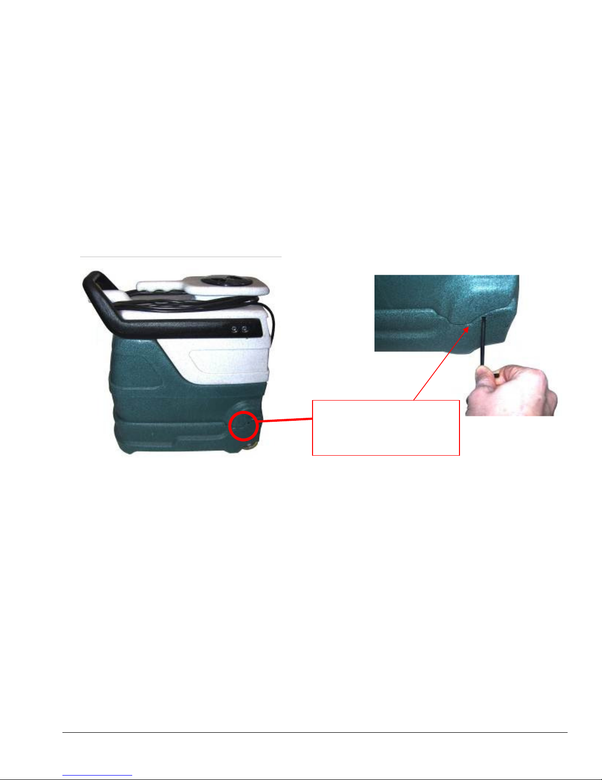
Descaling Heater – MA51H Only:
Insert 3/16” Allen wrench here to remove
1. Pour one gallon of descaling solution into the solution tank. For light scale build-up a mild acid solution
may be sufficient. Heavier build-up may require a stronger descaling solution.
2. With Cord plugged in, connect the solution hose& tool to the solution outlet male quick connect.
3. Direct the tool into a bucket or sink and turn the Solution Pump ON. Once you have solution at the
tool, turn the Heater ON and turn the Solution Pump OFF. Wait about 5-10 minutes and turn the
Heater OFF and turn the Solution Pump ON.
4. Spray the tool into the bucket or sink until most of the descaling solution has been pumped out of the
solution tank. Turn the pump OFF and disconnect the solution hose and tool.
5. Repeat the descaling process as needed to remove heavier scale build-up. Drain the remaining descaling
solution out of the solution tank. Rinse the solution tank, pump & heater with clean water and dispose of
the descaling solution and dirty water.
Removing Base to Access Heater – MA51H Only
To remove the base of the MA51H to access the heater, use a 3/16” Allen wrench to remove the two screws
holding the base to the solution tank. One screw is located on each side of the Power X Pro Spot Extractor.
screw and remove base from solution tank.
Also remove screw on other side of base.
Storage Prep and Freeze Protection Procedures:
Your Power X Pro Spot Extractor must be protected from freezing. Freezing can cause serious damage to the
pump, pump-out, auto-fill float valve, and any other component containing water. If the Power X Pro Spot
Extractor is transported or stored in freezing temperatures, the following procedures should be performed.
1. In a separate container mix 1 pint of water with 1 pint of automotive radiator anti-freeze. (Ethylene glycol
type). Mix well and pour into the solution tank.
2. Connect the solution hose to the solution outlet male quick connect and hold the tool over a bucket.
3. Turn the solution pump switch to the ON position. Spray the tool into the bucket until you see the anti-
freeze solution coming out of the jet into the bucket.
4. Turn the solution pump off.
5. Drain the remaining anti-freeze solution from the solution tank and the machine is ready for storage.
RETURNING THE POWER X PRO SPOT EXTRACTOR TO SERVICE
AFTER STORAGE OR FREEZE PROTECTION:
To return the Power X Pro Spot Extractor to service, the anti-freeze must be flushed from the machine.
Flush the anti-freeze out of the machine by repeating the procedure above using one quart of clean water in
place of the anti-freeze solution.
20
Page 21
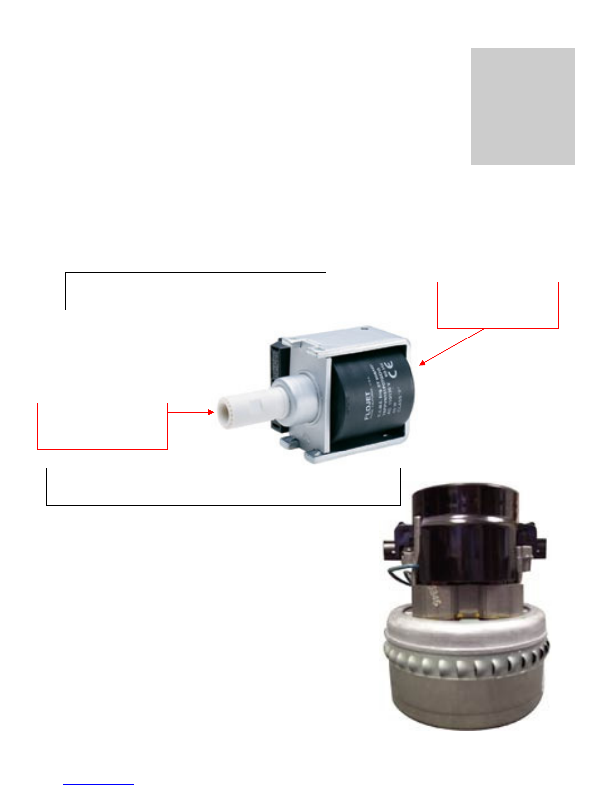
Parts
Section
3
Replacement parts available for repair of your Power X Pro Spot Extractor.
Power X Spotter Pump – AP30
SOLUTION OUTLET
1/8” FPT
Power X Spotter Vacuum Motor – AV06
SOLUTION INLET
1/8” FPT
21
Page 22

Item #
MA51 Component Description
Qty Needed
NM5090-ST Solution Tank 1
NM5090-RT Recovery Tank 1
10-0383 6/32 x ¼ Phil Pan Blk Screw (Latch & Switch Plate) 8* / 6**
10-0400-D Latch 1
10-0412 C Channel For Spotter 2
10-0414 Rivet For Spotter Handle 4
10-0384 .125 Thick Nylon Washer 4
10-0385 .06 Thick Nylon Washer 4
NM5032 Flat Washer #8 SAE 5
10-0216 Allen Head Screw 4
10-0379 8-32 x 3/8" Screw 4
10-0405 1½" PVC SCH40 Slip Thread 1
10-0302-A Gasket Tank Lid 1
10-0416-A ABS Stand Pipe Black 1½" 1
10-0304 Spotter Cap And Float Assembly 1
10-0302 Tank Hatch & Rim Assembly Only 1
10-0419 Screw For Spotter Hatch 6
SP-3-H-BLK Handle - Black 1
NM5090-HANDLE Handle Assembly (Includes hardware) 1
10-0406 Nylon Barb 90 1/8 NPT ¼ 2
PP11-800091 1/8” NPT Bulkhead Fitting (80-0017-2) 1
BR130 Nipple Reducing 1/4” x 1/8” Hex 1**
BR070 Nipple 1/8” Hex 1*
AH102B Quick Connect 1/4” Male 1**
PAF03 Quick Connect 1/8” Male 1*
10-0434 Threaded Hose for Spotter 2.5
NA0839 Barb Nylon Straight 1/8 NPT X 4
NA0840 1/8" Strainer for Spotter 1
AP30 Pump For Spotter 1
10-0301 L Bracket For Spotter 1
10-0435 Oetiker Clamp 5
10-0303 Roller Blade Wheel 2
10-0387 5/16 x 1" Socket Head Bolt (For Wheels) 2
10-0022 Screw 1
10-0017 Deflector Screw 1
10-1028 Bottom Base Plate for Spotter 1
10-0492 Screw for Bottom Plate 4* / 2**
10-0014 Motor Mount Screws 2
10-0380 Vac Motor Plate Screw 10-32 x 3/8” 2
10-1024 Vac Motor Mounting Plate 1
AV06 Vacuum Motor 1
10-0386 Stamped Motor Screen 1
PS10-1030 Spotter Motor Gasket 1
10-0027-A Strain Relief Nut For Spotter 1
10-1025 Back Switch Plate (no heater) 1
10-0027 Pigtail Strain Relief Spotter 1
10-0448-B 20 Ft. Spotter/Air Mover Cord 1
PDRI01 On/Off Rocker Switch 1* / 2**
10-0400-C Latch Keeper 10-0400-C 1
NM4061 Screw 10-32 x 1/2” BH SOC SS 1
NM4081 NUT 10-32 NYLOCK SS 1
* For older style units / ** For newer style units
22
Page 23
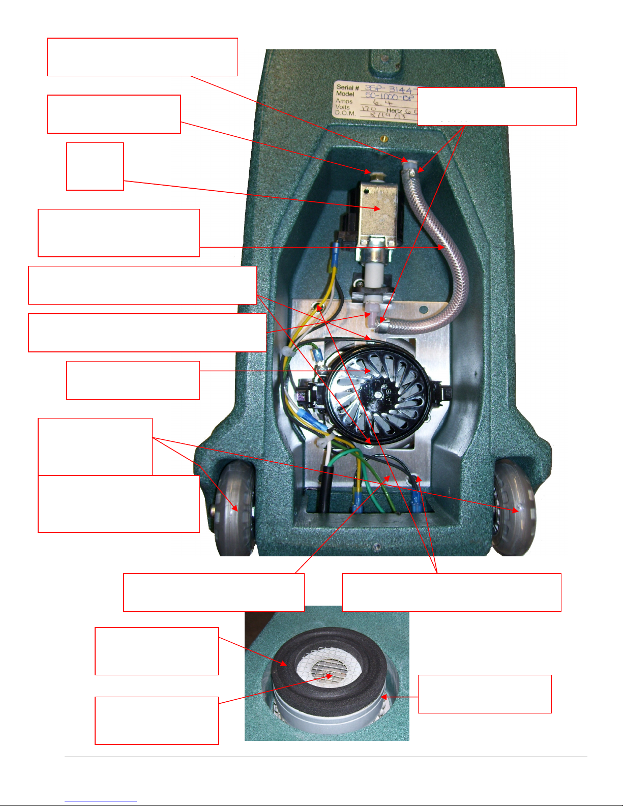
1/4” NYLON BARB X 1/8” MPT
NA0839
1/8” HEX NIPPLE
BR070
PUMP
AP30
1/4” ID THREADED HOSE
10-0434
SCREW VAC MOTOR MOUNT (QTY 2)
10-0014
1/4” NYLON BARB/ ELBOW – 1/8” MPT
10-0406
VACUUM MOTOR
AV06
WHEELS (QTY 2)
10-0303
SCREW 5/16 X 1” SOC HD
FOR WHEEL MOUNT
10-0387 (QTY 2)
MA51
OETIKER HOSE CLAMP
10-0435
PLATE VAC MOTOR MOUNT
10-1024
VACUUM GASKET
PS10-1030
VACUUM SCREEN
10-0386
SCREW VAC MOUNT PLATE (QTY 2)
10-0380
VACUUM MOTOR
AV06
23
Page 24
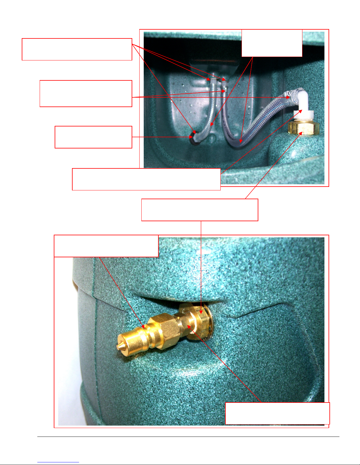
MA51
1/4” NYLON BARB X 1/8” MPT
NA0839
OETIKER HOSE CLAMP
10-0435
ACORN STRAINER
NA0840
1/4” NYLON BARB/ ELBOW 1/8” MPT
10-0406
1/4” ID HOSE
10-0434
1/8” NPT BULKHEAD FITTING
PP11-800091
1/4” MALE QUICK CONNECT
AH102B
24
1/4” X 1/8” HEX NIPPLE
BR130
Page 25
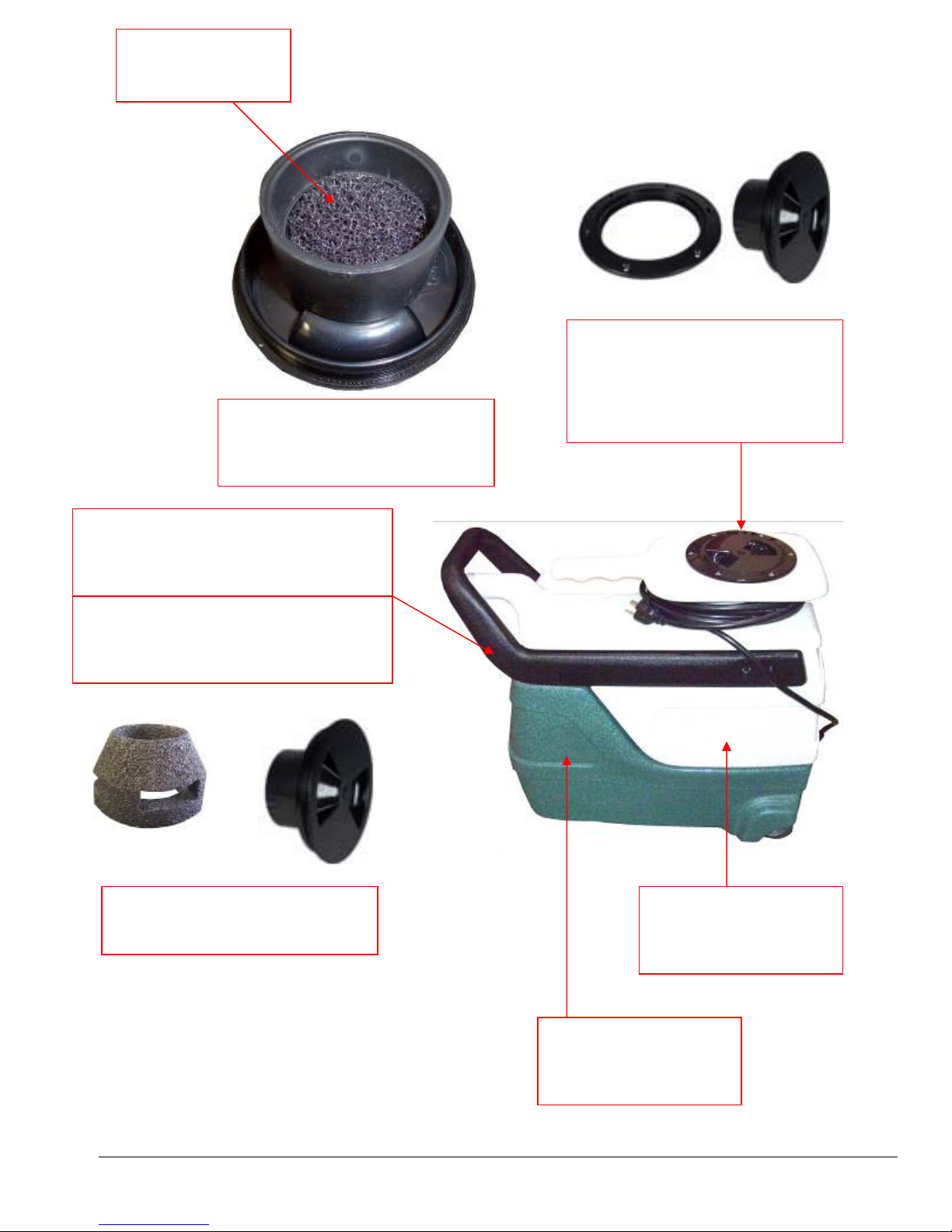
VACUUM FILTER
10-0431
MA51
SPOTTER HATCH COVER
BOTTOM VIEW
SPOTTER HANDLE ASSEMBLY
NM5090-HANDLE
HANDLE SLIDE ASSEMBLY
50-0001A
SPOTTER HATCH & COVER
10-0302
GASKET – 10-0302-A
SCREWS – 10-0419 (QTY 6)
SPOTTER COVER & FLOAT
10-0304
25
RECOVERY TANK
NM5090-RT
SOLUTION TANK
NM5090-ST
Page 26
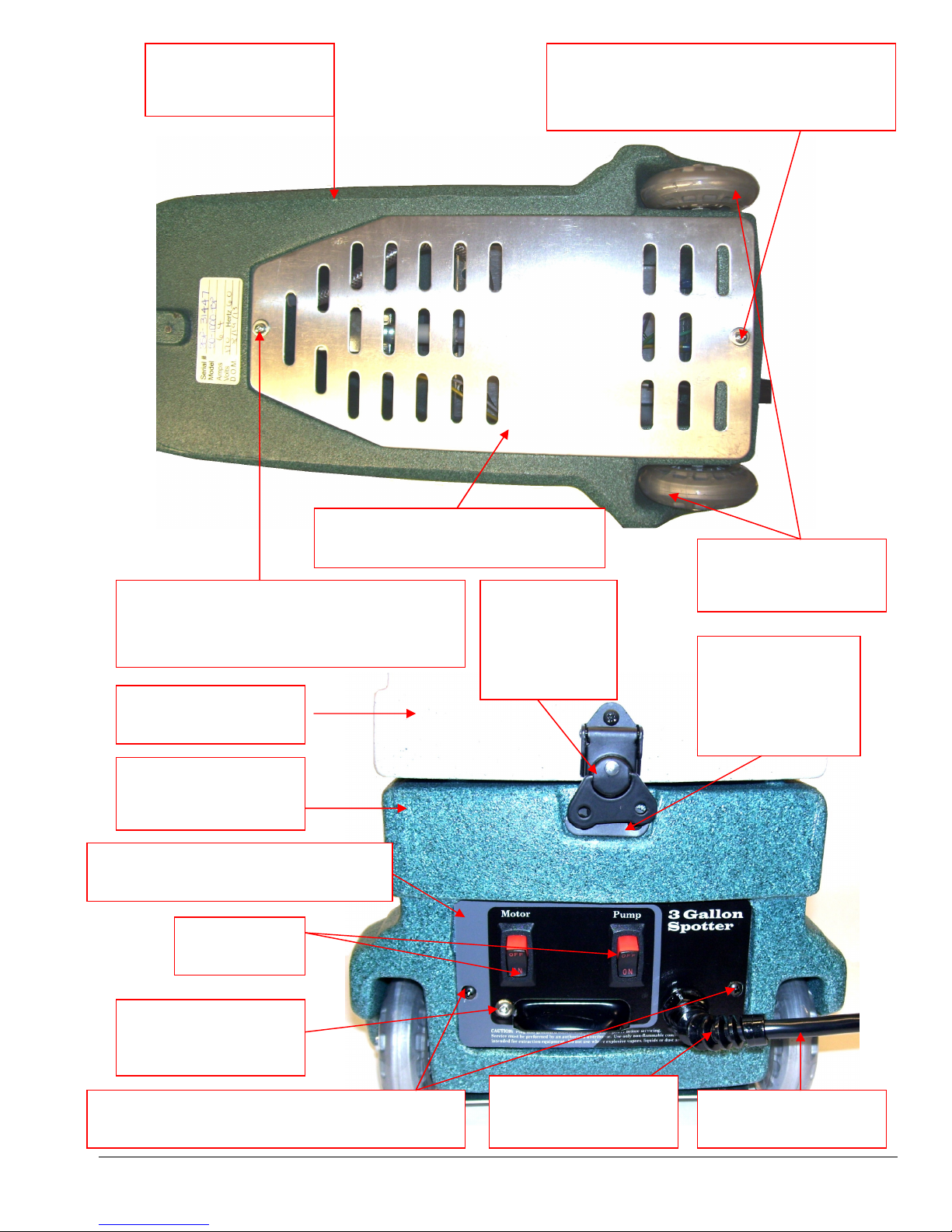
MA51
SCREWS
– 10-0387
NUT
– 10-0027
-A
SOLUTION TANK
NM5090-ST
SCREW FOR BASE PLATE - 10-0482
FLAT WASHER – NM5032
(Old style -4) (New Style – 2)
BOTTOM BASE PLATE MA51
10-1028
SCREW FOR BASE PLATE - 10-0482
FLAT WASHER – NM5032
(Old style -4) (New Style – 2)
RECOVERY TANK
NM5090-RT
SOLUTION TANK
NM5090-ST
MA51 BACK / SWITCH PLATE
10-1025
SWITCH
PDRI01
LATCH
10-0400D
SCREWS
10-0383 (QTY
WHEELS (QTY 2)
10-0303
LATCH KEEPER
10-0400C
SCREWS
10-0383 (QTY 2)
GROUND SCREW
NM4061
NUT – NM4081
SCREW 6-32 X 1/4”
10-0383 - (Old style -4) (New Style – 2)
STRAIN RELIEF
10-0027
26
POWER CORD
10-0448-B
Page 27

Item #
MA5
1H
Component Description
Qty Needed
NM5090-ST Solution Tank 1
NM5090-RT Recovery Tank 1
10-0383 6/32 x ¼ Phil Pan Blk Screw (Latch & Switch Plate) 6
10-0400-D Latch 1
10-0412 C Channel For Spotter 2
10-0414 Rivet For Spotter Handle 4
10-0384 .125 Thick Nylon Washer 4
10-0385 .06 Thick Nylon Washer 4
NM5032 Flat Washer #8 SAE 5
10-0216 Allen Head Screw 4
10-0379 8-32 x 3/8" Screw 4
10-0405 1½" PVC SCH40 Slip Thread 1
10-0302-A Gasket Tank Hatch 1
10-0416-A ABS Stand Pipe Black 1½" 1
10-0304 Spotter Cap And Float Assembly 1
10-0302 Tank Hatch & Rim Assembly Only 1
10-0419 Screw For Spotter Hatch 6
SP-3-HS-GRNGRAN Base Spotter Skirt w/ Heat 1
10-0831 S/R Bracket 1
10-0832 S/R Strap Bolts 2
AP30 Pump For Spotter 1
BR070 Nipple 1/8” Hex Brass 1
PSA100901 Pressure Relief Valve 175psi 1
BR220 Brass Plug 1/8” 1
NM5087 Bulkhead Fitting 1/4” Brass 2
BR020 Barb 3/8” x 1/4” MPT Brass 4
PH07 Hose Clamp 6
10-0843 Hose 3/8” ID Black LP 1
10-0434 Threaded Hose for Spotter 1
NA0839 Barb Nylon Straight 1/8 NPT X 1/4” Barb 4
NA0840 1/8" Strainer for Spotter 1
10-0301 L Bracket For Spotter 1
10-0828 90 Deg Brass Elbow 1/8” MPT 1
10-0022 Screw 3
10-0017 Deflector Screw 1
PA076 Female Spade Connector Insulated – Blue 10
T-WPUR Purple Wire
BR282 Elbow 90 Deg 1/4” Street M-F 1
BR252 Tee 1/4” Street M-F-F 1
10-0843 Hose 3/8” ID Black LP – Sold per inch 24
BR292 Elbow 90 Deg 1/4” F-F 1
NM5069 Check Valve 1/4” MPT 1
80-0014 Elbow 90 Deg 1/4” FPT x 3/8” barb 1
BR082 1/4” Close Nipple Brass 1
AH102B 1/4” Male Quick Connect 1
PSA101500B Heater – Element Only 1
10-0814 Temperature Switch Auto Reset 1
10-0814-B Temperature Switch Manual Reset 1
10-0907 Strain Relief for Heater 1
27
Page 28

Item #
MA51
H Component De
scription
Qty Needed
10-0906 Heater Box Only 1
10-0900 Heater Body Only 1
10-0801-G Insulation for Heater Box 1
PSA100910 Heater Assembly Complete with all Fittings & Temperature Switches 1
PSA001 High Pressure – High Temperature Hose Assembly 1
SP-3-H-BLK Handle - Black 1
NM5090-HANDLE Handle Assembly (Includes hardware) 1
10-0387 5/16 x 1" Socket Head Bolt (For Wheels) 2
10-0303 Roller Blade Wheel 2
10-0822 Exhaust Grate 2
10-0419-A Screw For Exhaust Grate 2
10-0014 Motor Screws 2
10-0380 Screw 10-32 x 3/8” 2
10-1024 Vac Motor Mounting Plate 1
AV06 Vacuum Motor 1
10-0386 Stamped Motor Screen 1
PS10-1030 Spotter Motor Gasket 1
10-0027-A Strain Relief Nut For Spotter 1
T-WBLA Black Wire
10-0027 Pigtail Strain Relief Spotter 1
10-0448-B 20 Ft. Spotter/Air Mover Cord 1
PDRI01 On/Off Rocker Switch 3
10-1026 Back Switch Plate (with heater) 1
10-0400-C Latch Keeper 10-0400-C 1
NM4061 Screw 10-32 x 1/2” BH SOC SS 3
NM4255 Washer Flat #10 SS 2
NM4081 NUT 10-32 NYLOCK SS 1
28
Page 29
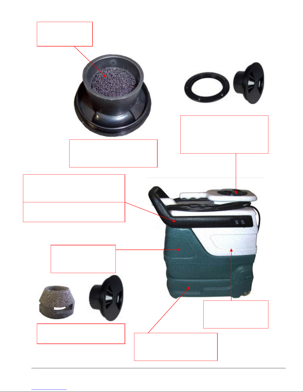
VACUUM FILTER
10-0431
MA51H
SPOTTER HATCH COVER
BOTTOM VIEW
SPOTTER HANDLE ASSEMBLY
NM5090-HANDLE
HANDLE SLIDE ASSEMBLY
50-0001A
SOLUTION TANK
NM5090-ST
SPOTTER HATCH & COVER
10-0302
GASKET – 10-0302-A
SCREWS – 10-0419 (QTY 6)
SPOTTER COVER & FLOAT
10-0304
SPOTTER BASE W/ HEAT
SP-3-HS-GRNGRAN
29
RECOVERY TANK
NM5090-RT
Page 30
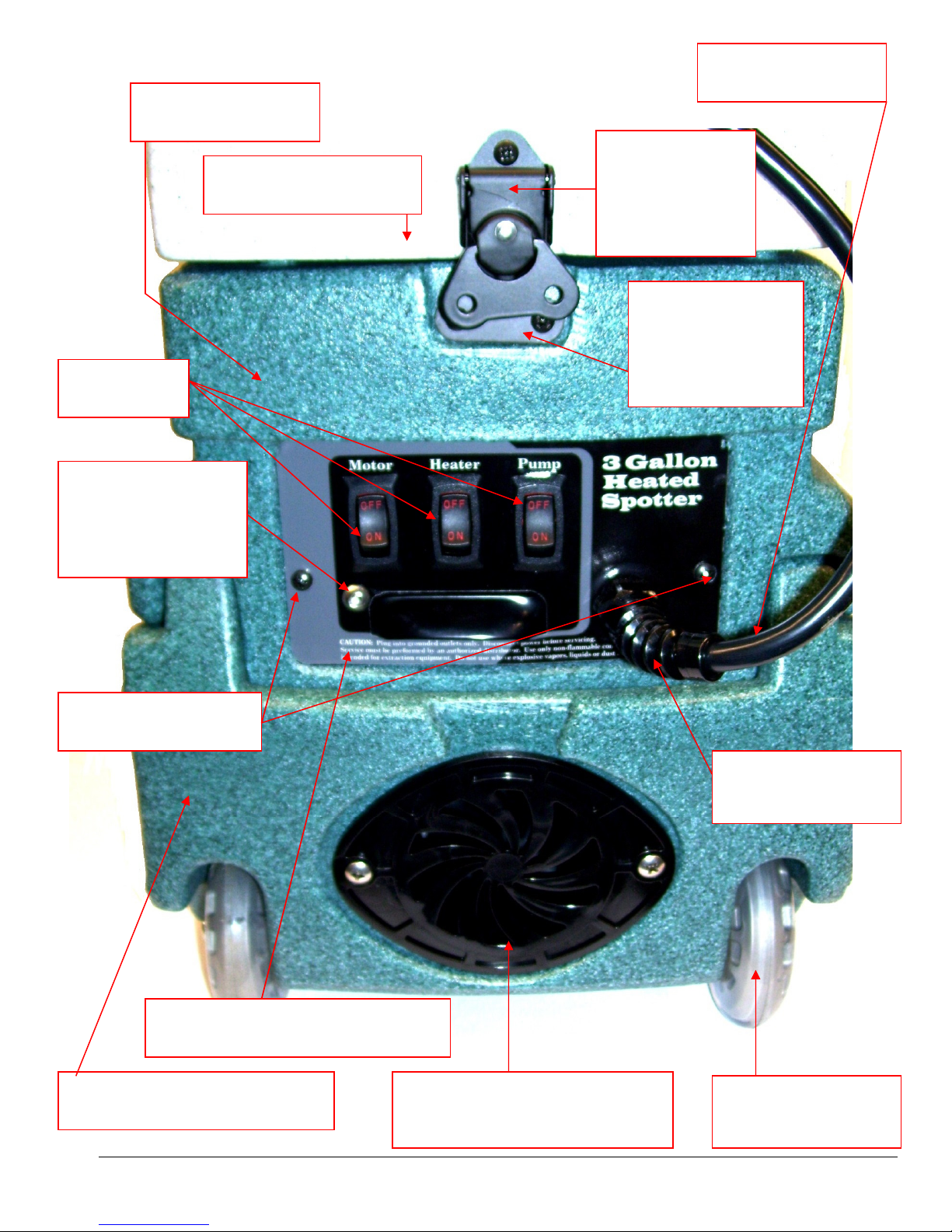
NUT 10
-
0027
-A
SCREWS
– 10-0387
NM4081
SOLUTION TANK
NM5090-ST
SWITCH
PDRI01
GROUND SCREW
NM4061
NUT
RECOVERY TANK
NM5090-RT
POWER CORD
10-00448-B
MA51H
LATCH
10-0400-D
SCREWS
10-0383 (QTY 2)
LATCH KEEPER
10-0400-C
SCREWS
10-0383 (QTY 2)
SCREW 6-32 X 1/4”
10-0383
MA51H BACK / SWITCH PLATE
10-1026
SPOTTER BASE MA51H
SP-3-HS-GRNGRAN
VENT GRATE
SCREWS 10-0419-A (QTY 2)
STRAIN RELIEF
10-0027
WHEELS (QTY 2)
10-0303
30
Page 31
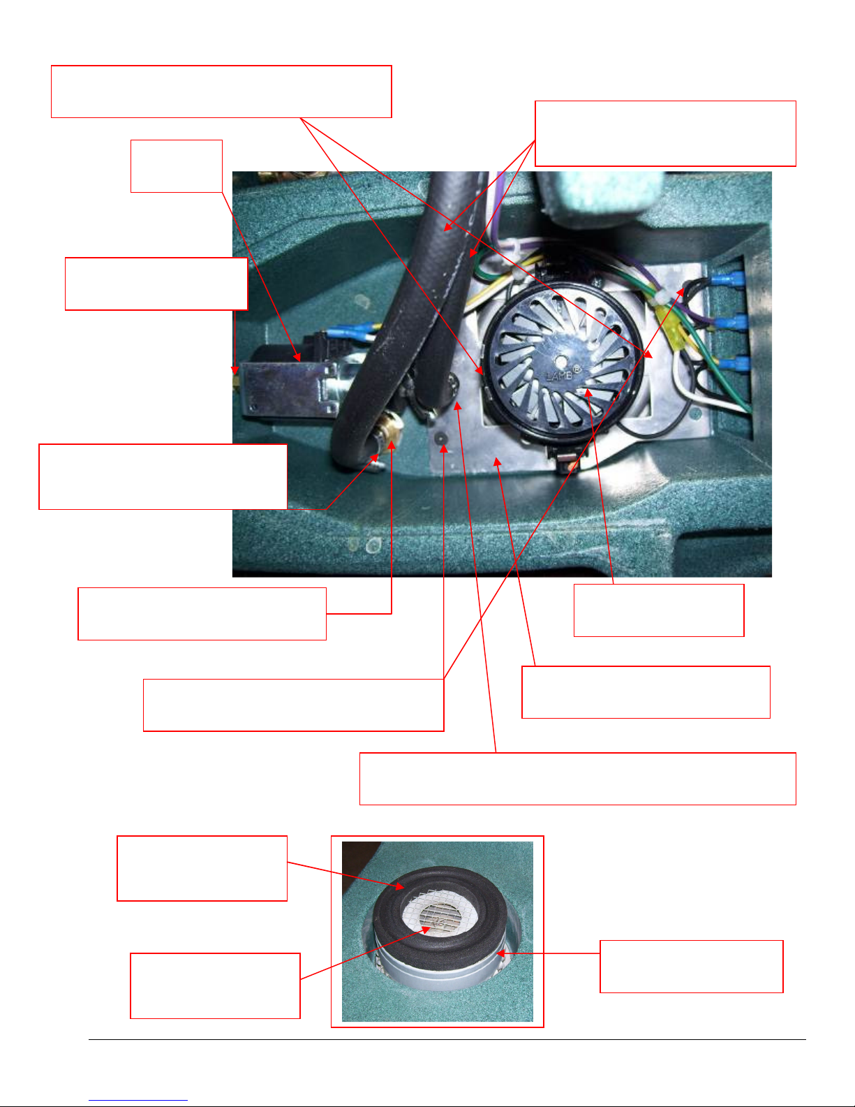
SCREW VAC MOTOR MOUNT (QTY 2)
10-0014
PUMP
AP30
1/8” HEX NIPPLE
BR070
MA51H
HOSE 3/8” ID HI-TEMP BLACK
BARB 3/8” X 1/4” MPT
BR020
BULKHEAD FITTING 1/4”
NM5087
SCREW VAC MOUNT PLATE (QTY 2)
10-0380
VACUUM GASKET
PS10-1030
VACUUM MOTOR
AV06
PLATE VAC MOTOR MOUNT
90 DEGREE BRASS ELBOW 3/8” BARB X 1/8” MPT
10-0828
VACUUM SCREEN
10-0386
31
VACUUM MOTOR
AV06
Page 32
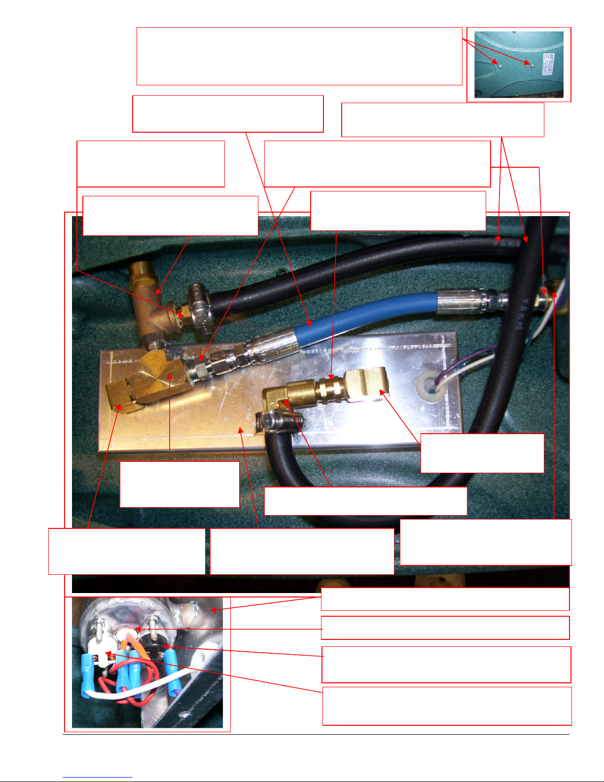
10-0843 (Sold per inch)
MA51H
COMPLETE WITH FITTINGS
Heater
Assembly
Heater is secured to Spotter Base with two screws & Flat Washers:
2 - SCREW 10-32 x 1/2” BH SOC SS – NM4061
2 – WASHER FLAT #10 SS – NM4255
BARB 3/8” X 1/4” MPT
BR020
PRESSURE RELIEF VALVE
PSA100901
HOSE HP 1/4”ID HI-TEMP BLUE
1/4” JIC FITTINGS – PSA001
HOSE LP 3/8” ID HI-TEMP BLACK
ADAPTER 1/4” MPT X 1/4T M FLARE
BR126
CHECK VALVE 1/4” MPT
NM5069
TEE 1/4” STREET
BR252
ELBOW 90˚ 1/4” STREET
BR282
ELBOW 90˚ 1/4” FPT X 3/8” BARB
HEATER 600W
PSA100910
ELBOW 90˚ 1/4” F-F
BR292
BULKHEAD FITTING 1/4”
NM5087
HEATER OUTER SHELL ONLY – PSA100900
HEATER ELEMENT ONLY – PSA101500B
TEMPERATURE SWITCH AUTO RESET
10-0814
TEMPERATURE SWITCH MANUAL RESET
10-0814-B
32
Page 33
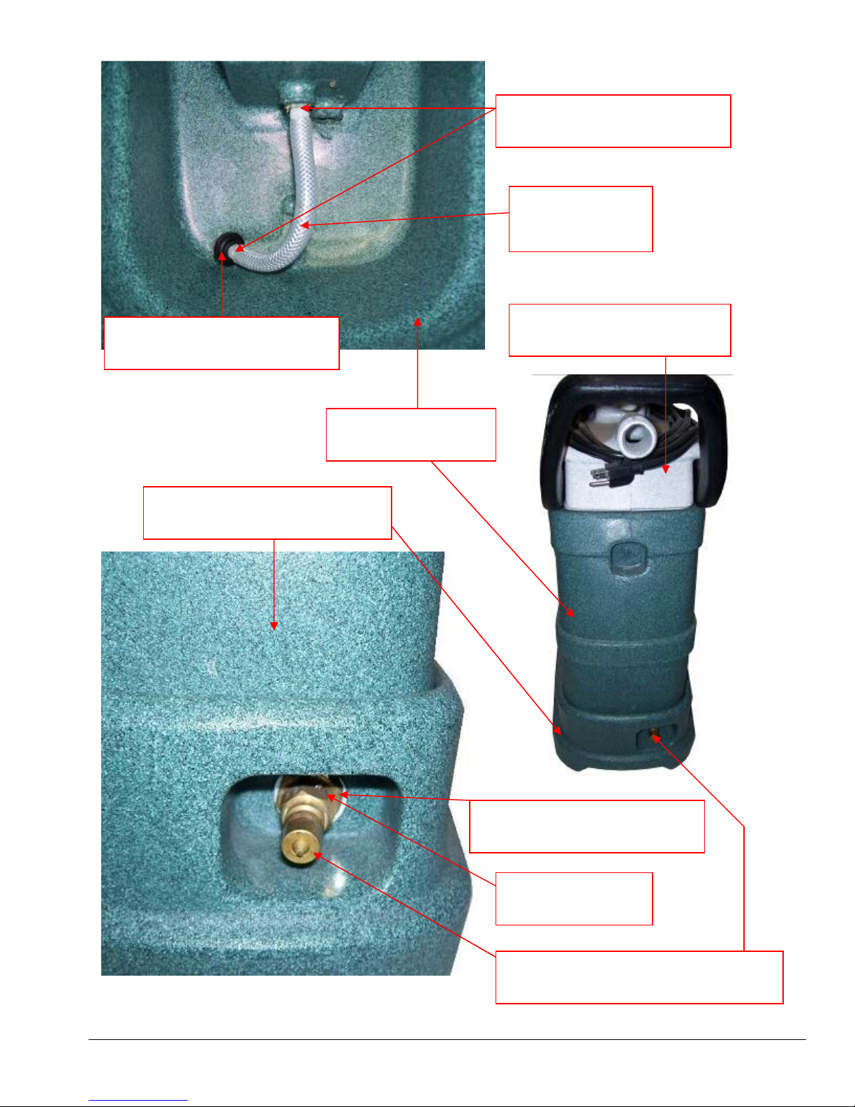
ACORN STRAINER 1/8” FPT
NA0840
SPOTTER BASE MA51H
SP-3-HS-GRNGRAN
SOLUTION TANK
NM5090-ST
33
MA51H
BARB 1/4” X 1/8” MPT
NA0839
1/4” ID HOSE
10-0434
RECOVERY TANK
NM5090-RT
BULKHEAD FITTING 1/4”
NM5087
NIPPLE 1/4” HEX
BR072
1/4” MALE QUICK CONNECT
AH102B
Page 34
1
11
10
2
3
13
12
5
7
4
6
9 3
8
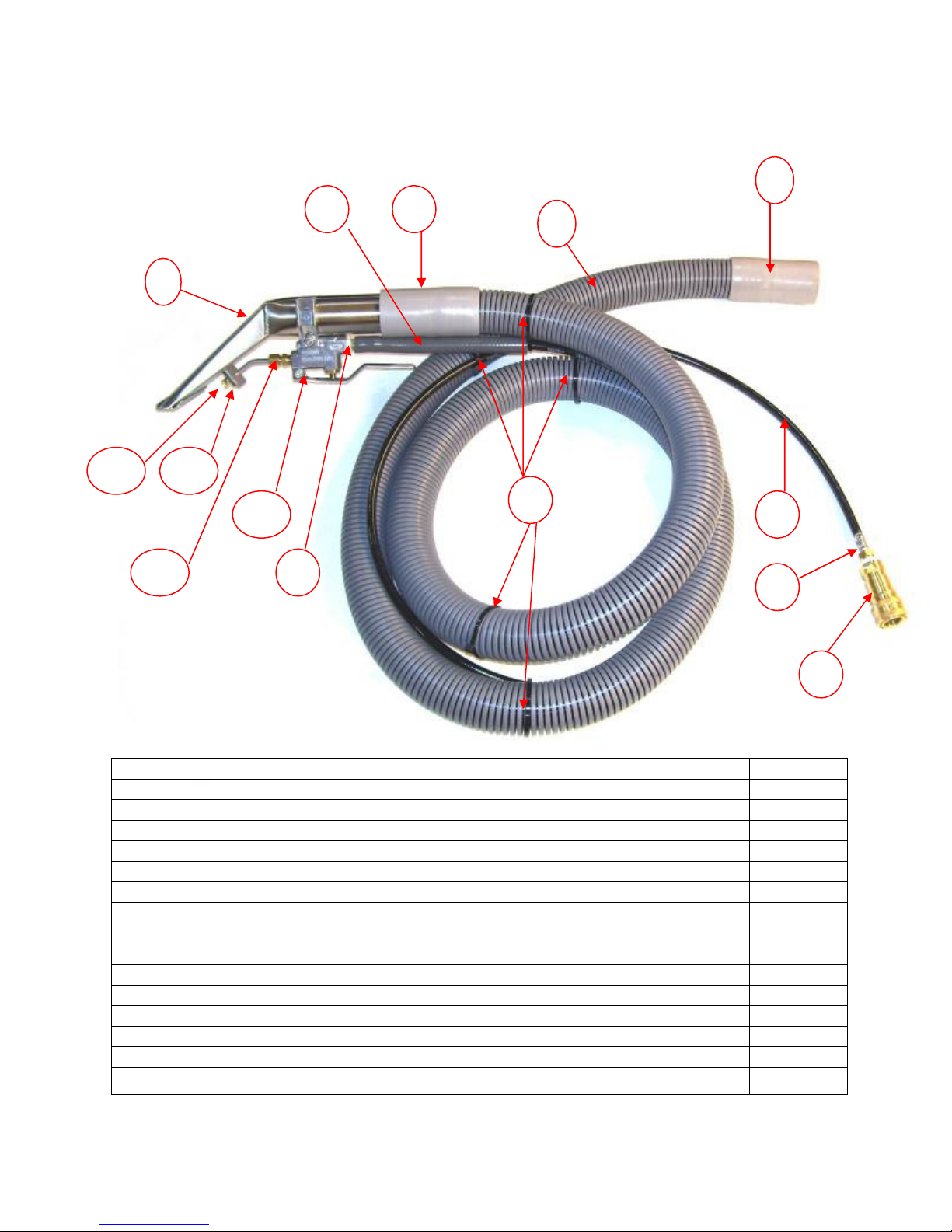
AW55H HOSE & TOOL ASSEMBLY
1
2
3
4
5
6
7
8
9
10
11
12
13
NS
ITEM# Description QTY
PA205
AH35
PP08-805088
AH101B
NA40A
AH01
AH02
100003
AH90
PMV124V5
PMF8002
PMF011
BR304
PMV124V5B
1-1/4" Gray Vacuum Hose (Sold per foot) 7'
3/16" HP Black Solution Hose (Sold per Inch) 96"
3/8" LP Gray Solution Hose (Sold per foot) 0.5
Solution Valve with lever & mounting bracket 1
3.5" SS Upholstery Tool 1
1-1/4" Hose Cuff 2
1/4" QD Female 1
1/8" Hose End for 3/16" hose 1
1/4" Hose End for 3/16" hose 1
Wire Tie Black 7" 5
Tee Jet for hand tool 8002 1
Retaining Plate for jet on hand tool 1
Compression fitting 1/8” MPT 1
Valve Repair Kit 1
34
Page 35

Section
4
Limited Warranty
Your Power X Pro Spot Extractor is designed to give you years of reliable service. If a problem should arise
use the troubleshooting section in the operation manual to diagnose and correct the problem if possible.
If you are unable to determine the cause or solution to the problem contact your distributor or Hydro-Force
for assistance.
Hydro-Force warrants the roto-molded tanks and base of the Power X Pro Spot Extractor to be free from
defects in material or workmanship for five years from the date of purchase.
All other components of the Power X Pro Spot Extractor are warranted to be free of defects in material and
workmanship for one year from the date of purchase.
During the warranty period, Hydro-Force will, at its option repair or replace components which prove to be
defective. This warranty does not provide for replacement of complete units due to defective components.
Any costs for transportation or related service labor are not covered in this warranty. Replacement parts are
warranted only for the remainder of the original warranty period.
This warranty shall not apply to defects resulting from improper operation, lack of maintenance,
unauthorized modification, chemical incompatibility, misuse, abuse or exposure to freezing temperature
conditions. It does not cover normal wear items such as o-rings, valve seals, pump seals, hoses, jets, cords,
batteries, or other items which require replacement as a result of ordinary usage.
To obtain warranty service for the Power X Pro Spot Extractor, contact your distributor or Hydro-Force. If
the spotter must be returned to Hydro-Force or an authorized service center, the purchaser shall prepay
shipping charges for products returned for warranty service. No returned items will be accepted by HydroForce without prior authorization. All returns must have a return authorization number, issued by HydroForce, clearly marked on the exterior of the package.
Hydro-Force makes no other warranty either expressed or implied with respect to this product.
The remedies provided herein are the purchaser’s sole and exclusive remedies. In no event shall Hydro-Force
be liable for any direct, indirect, special, incidental or consequential damages.
This warranty gives you specific legal rights. You may also have other rights which vary from jurisdiction to
jurisdiction.
35
 Loading...