

Page 1
1
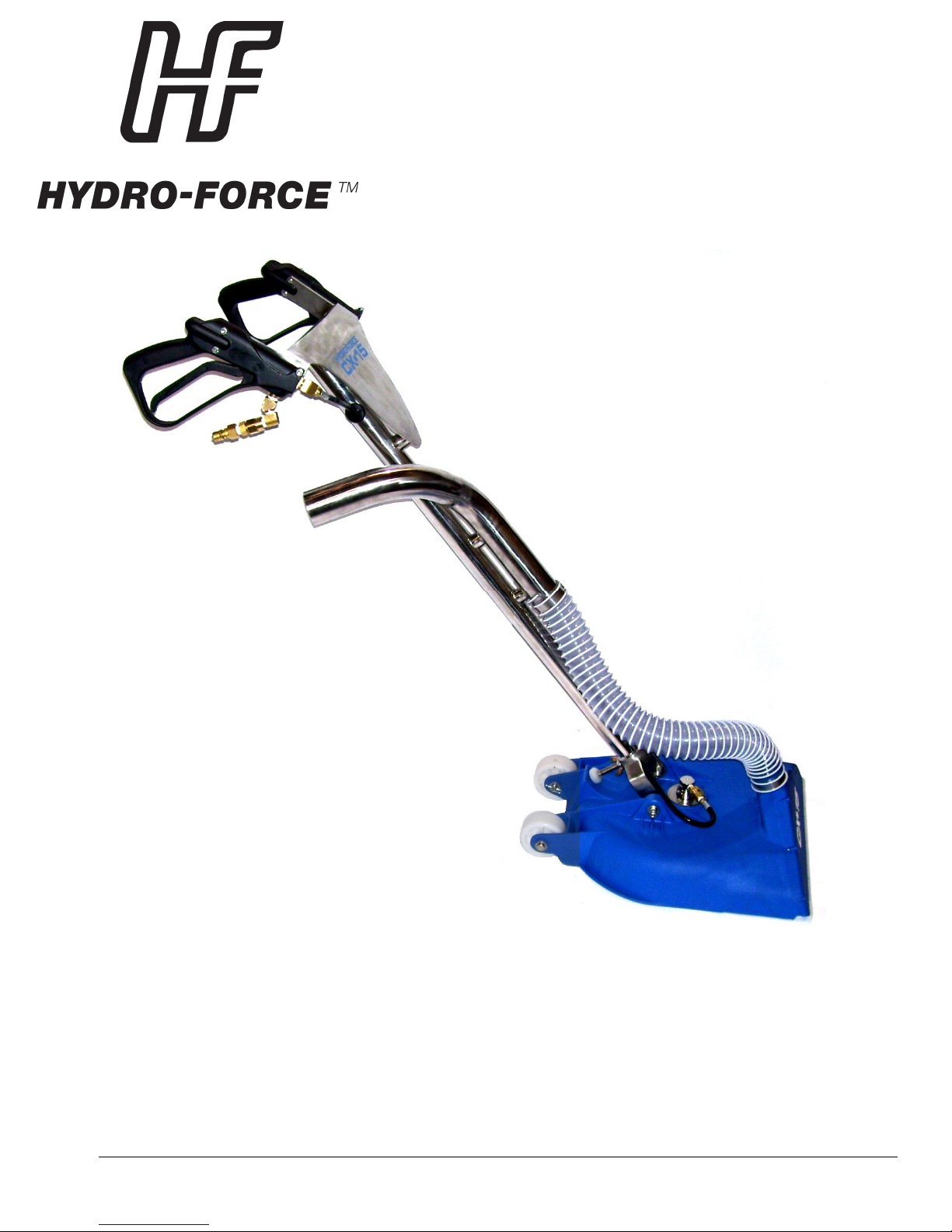
CX-15 ROTARY CARPET
EXTRACTOR
OPERATOR’S MANUAL
Hydro-Force
4282 South 590 West
Salt Lake City, UT 84123
801-268-2673
801-268-3856 FAX
LMANAW115
Revised: 08-26-2014
Page 2
2
CX-15 Operator’s Manual
TABLE OF CONTENTS
TOPIC PAGE #
• Introduction 3
• Technical Specifications 4
SECTION 1: Operational Safety
• Safety 5
SECTION 2: Operation Procedures
• Spray Bar & Jet Selection 6
• Pressure & Flow Requirements 7
• Handle Adjustment 7
• Hose Connection 7
• Cleaning Procedures 8
• Shutdown Procedure 9
SECTION 3: Maintenance/ Technical
• Troubleshooting 10
• Maintenance 11
• Drawings & Parts Lists 15
• Warranty 24
Page 3

3
Introduction
Congratulations on your purchase of the Hydro-Force CX-15 Rotary Carpet
Extractor. The CX-15 is designed to give professional cleaning performance with
either truck mounted or portable extractors. Years of experience, engineering, and
planning have gone into the design and manufacturing of the CX-15. We take a
great deal of pride in the CX-15; our goal is no less than your complete
satisfaction.
This manual will provide users with the knowledge required to operate the Hydro
-Force CX-15 safely, to understand how to properly operate and maintain the
machine, and to ensure that the equipment operates at its maximum performance
level.
All users must read and understand this manual completely before
operating the machine. Place this manual in a secure location for future
reference.
Always maintain this manual in legible condition adjacent to the Hydro-Force CX15, or place in a secure location for future reference.
Any questions pertaining to the operating or servicing of this unit should be
directed to your nearest Hydro-Force distributor.
This manual is written specifically for the Hydro-Force CX-15 rotary extractor
units manufactured by:
Hydro-Force
4282 South 590 West
Salt Lake City, UT 84123
801-268-2673
801-268-3856 FAX
Information in this manual is subject to change without notice and does not
represent a commitment on the part of Hydro-Force or its parent or affiliated
companies.
Page 4
4
Technical Specifications
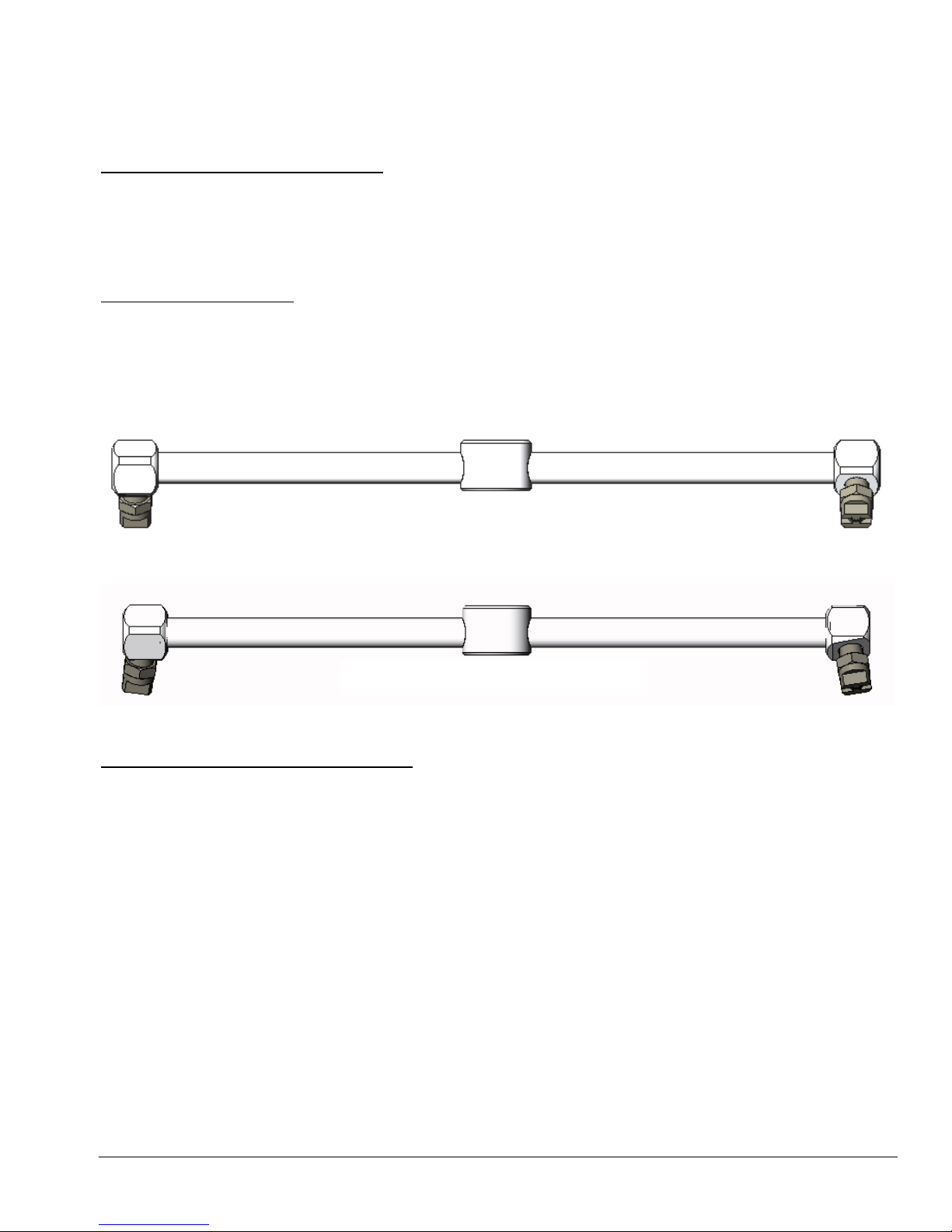
RESIDENTIAL SPRAY BAR
C
OMM
ERCIAL SPRAY BAR
CX-15 Rotary Carpet Extractor
Height: 46.3” with handle
Length: 19”
Width: 17.3”
Weight: 15.8 lbs.
Standard Equipment
CX-15 Carpet Cleaning Tool
Spray Bars: Residential 40° Drive Angle* / 0° Kick Angle**/ 11002 SS Jets
Commercial 30° Drive Angle* / 7.5° Kick Angle**/ 1502 SS Jets
*See Operation Procedure Section on page 6 for the definition of Drive Angle.
**See Operation Procedure Section on page 6 for the definition of Kick Angle.
Additional / Optional Equipment
Hydro-Force Pro Solution Hose 1/4” x 25’ Blue: (w/o Quick Connects) AH170
Hydro-Force Pro Solution Hose 1/4” x 50’ Blue: (w/o Quick Connects) AH176
Hydro-Force Pro Solution Hose 1/4” x 100’ Blue: (w/o Quick Connects) AH172
Hydro-Force Pro Solution Hose 1/4” x 150’ Blue: (w/o Quick Connects) AH174
1/4” Male Quick Connect: AH102B
1/4” Female Quick Connect: AH101B
Ball Valve 1/4” M-F AH54
Vacuum Hose 2” x 50’ with Cuffs – Blue AH32H
Vacuum Hose 2” x 50’ with Cuffs – Orange AH30H
Vacuum Hose 2” x 50’ with Cuffs – Grey AH34
Vacuum Hose 1.5” x 50’ with Cuffs – Blue AH38CH
Vacuum Hose 1.5” x 50’ with Cuffs – Orange AH31H
Vacuum Hose 1.5” x 50’ with Cuffs – Grey AH36BH
Vacuum Hose 1.5” x 25’ with Cuffs – Blue AH38BH
Vacuum Hose 1.5” x 25’ with Cuffs – Orange AH29H
Vacuum Hose 1.5” x 25’ with Cuffs – Grey AH36BH
Cuff 2” for 1.5” Hose AH46
Page 5
5
Safety
Section
1
WARNING! This tool must be protected from freezing conditions which may
damage the valves, swivels, hoses and other components.
• Freezing of water in this tool will cause damage. The CX-15 must be protected from freezing temperature.
Store, transport, and use this equipment only in temperatures well above freezing. (32ºF or 0ºC). If you suspect
the CX-15 has been frozen, do not try to operate until you are sure it has thawed completely.
• If the tool cannot be stored or transported in a warm environment, it can be guarded from freezing by running
an anti-freeze solution through the tool or using compressed air to blow the water out of the tool. If anti-freeze
is used, the anti-freeze solution must be completely flushed from the tool before it is returned to service.
WARNING! Rotating Spray Bar can cause Injury
• Keep Hands & Feet away from CX-15 head while operating tool.
• Keep all body parts, hair, and loose clothing away from openings and moving parts. Always wear appropriate
clothing and safety equipment when operating unit.
• Disconnect Solution Hose from CX-15 before attempting to change Spray Bars.
WARNING!
• Do not clean with solutions that are at temperatures above 250ºF.
• HP hoses may rupture if worn or damaged. Do not use tool if solution hose covering is cut, bulging, or
otherwise damaged. Examine HP solution hoses daily and replace or repair hoses as needed.
***Use common sense to protect yourself and others while using this equipment.***
• Keep pets and children away from the machine when in use.
High Pressure water at high temperatures can cause Injury
Page 6
6
Operation Procedures
Section
2
SET UP AND OPERATION
1. Spray Bar Selection:
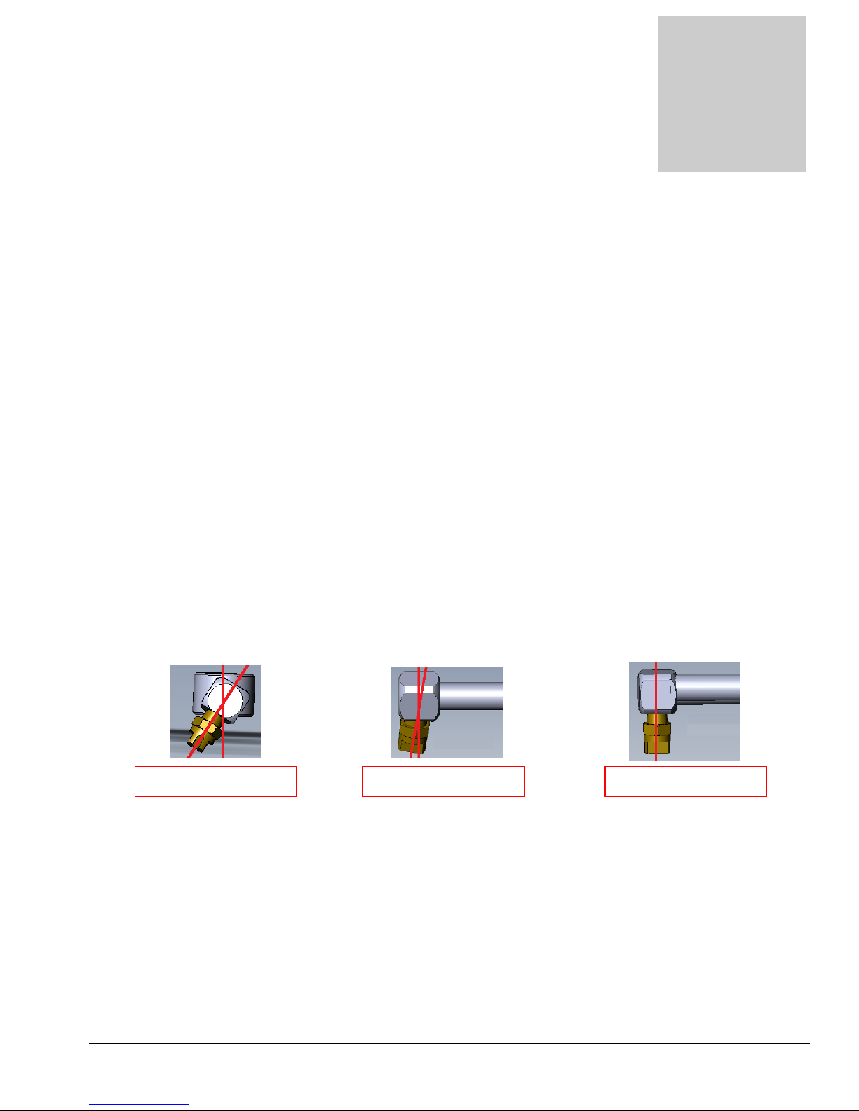
The different spray bars are designed for different carpet types. Two different Spray Bars are included
with the CX-15:
Residential Spray Bar: 40° Drive Angle / 0° Kick Angle / 11002 SS Jets
Commercial Spray Bar: 30° Drive Angle / 7.5° Kick Angle/ 1502 SS Jets
Spray Bars are stamped with an R for Residential or C for Commercial for easy identification.
The
Drive Angle
along with the spray jet and water pressure in determining the spray impact and rotation speed of the CX-15
Spray Bar. A Drive angle of 0° would point straight down at the floor. While a Spray Bar with a 0° Drive
angle would have high spray impact, the Spray Bar would not rotate. A Spray Bar with a 90° Drive Angle
would rotate very fast, but would have no spray impact. Extensive testing was run to find the optimum Drive
Angle, jet and pressure combination for maximum performance.
The
Kick Angle
Angle is a major factor along with the spray jet and water pressure in determining the cleaning area covered
by the CX-15. A Kick Angle of 0° points straight down. A jet with a wide spray pattern can be used with a 0°
Kick Angle. A more narrow spray pattern jet must be used with a Spray Bar with a greater Kick Angle to
attain coverage of the maximum cleaning area.
We recommend using the different Spray Bars only on the following carpet types:
RESIDENTIAL SPRAY BAR: Carpet with the potential to “bloom”. Cut Pile Carpets such as Saxony,
Plush Piles, Sculptured or Textured Carpets & Frieze Carpets.
COMMERCIAL SPRAY BAR: Durable Closed Loop type carpets.
Install the correct Spray Bar for the type of carpet you will be cleaning.
If you are unsure of which Spray Bar to use, select the Residential Spray Bar.
The Residential Spray Bar is less likely to cause fiber damage.
Refer to the Spray Bar Installation Instructions on Page 12.
is the angle of the spray jet in relation to the floor. The Drive Angle is a major factor
is the angle of the spray jet out from the center axis of the Spray Bar rotation. The Kick
7.5° KICK ANGLE 0° KICK ANGLE DRIVE ANGLE
CAUTION:
o Using the Commercial Spray Bar on Cut Pile carpets may cause damage to carpet fibers.
o Using different jet sizes than those noted above may cause damage to the carpet fibers.
Page 7
7
2. Water Pressure & Flow Requirements:
The solution pump providing the water pressure to operate the CX-15 requires the following:
Adjust your system solution pressure for the best cleaning performance on the type of carpet you will
be cleaning.
Required Pump Flow & Pressure: 1.80gpm @ 800psi
Recommended pressure for Residential Spray Bar on Cut Loop Carpet – 400psi
Recommended pressure for Commercial Spray Bar of Closed Loop Carpet – 500-800psi
Operation with a lower pressure setting will slow the Spray Bar rotation and may require more
time to clean the carpet properly.
Operation with a higher pressure setting may cause the Spray Bar to spin too fast, exceeding the
recommended operation speed of the swivel. The increased agitation at higher pressures may
damage carpet fibers.
CAUTION:
o Exceeding the recommended pressure may cause damage to carpet fibers.
o Exceeding the recommended pressure may over spin the jet bar and damage the swivel.
3. Connection of Solution Hose:
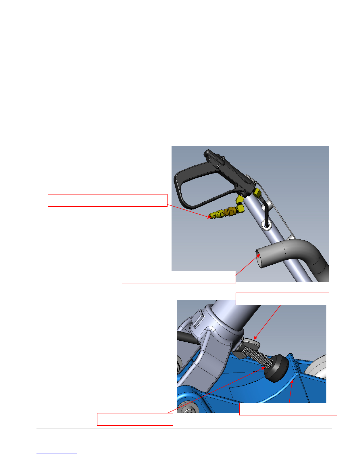
Connect the solution hose from your
extractor to the 1/4” Male Quick
connect on the Spray Gun Assembly on
the right side handle of the CX-15.
CONNECT SOLUTION HOSE HERE
4. Connection of Vacuum Hoses:
Connect the vacuum hose from your
extractor to the 2” Vacuum pipe on the
handle of the CX-15. A 2” cuff is
recommended and will fit over the
outside of the pipe. A 1-1/2” cuff can
be used. It will fit inside the pipe, but
may not seal as well.
5. Adjusting The Handle Stop:
The Handle Stop can be adjusted to set the
CX-15 handle height for comfortable
operation.
Loosen the Handle Stop Wing Nut.
Turn the Handle Stop Bolt IN or OUT as
needed to change the position of the handle
when the Handle Stop Bolt contacts the
Handle Stop on the CX-15 Main Body. The
CX-15 Handle should be adjusted such that
your arms are in a comfortable position
while keeping the CX-15 head level and the
Glide Plate on the carpet while pulling the
CX-15 back during each cleaning pass. Once
set, tighten the Handle Stop Wing Nut to
lock the Handle Stop Bolt in place.
HANDLE STOP BOLT
CONNECT VACUUM HOSE HERE
HANDLE STOP WING NUT
MAIN BODY HANDLE STOP
Page 8

8
6. Cleaning Procedure:
Determine Spray Bar to Use
It is up to the operator to ascertain which spray bar (residential or commercial) will be used, and the
solution pressure to use. See #1 above for information about this decision. If unsure of the proper spray
bar to use, clean the carpet in an inconspicuous area and inspect to make sure there is no fiber damage;
default to using the Residential Spray Bar if you’re still unsure.
Adjust Handle Stop
The handle stop’s purpose is to allow forward movement with the CX-15. On some carpet types, because
of pile type, or lay of the nap, the CX-15 is unable to be pushed forward. The design of the glide permits
extreme water removal when moving backwards, but can sometimes “suck down” when moving forward.
To break this vacuum seal, the operator pushes down on the handle, the handle stop bolt contacts the top
of the CX-15 deck and the front of the CX-15 is raised off the carpet – breaking the vacuum seal.
Vacuum Carpet
Vacuum the carpet or use a counter rotating brush machine to remove debris and dry soil from the
carpet.
Prespray Carpet
Prespray the carpet with your selected cleaning solution. Allow it to dwell for 5 or 10 minutes but do not
allow it to dry before applying the extraction process using the CX-15.
Clean and Extract with CX-15
Pull the handle back to tilt the CX-15 back onto its wheels and roll the CX-15 into position to make the
first cleaning pass.
Simultaneously squeeze the trigger on the spray gun and pull the CX-15 back. This achieves the cleaning
and extraction stroke. Note: Holding the solution on and not moving the tool at the same time will result
in a “clean circle” being created on the carpet. These can be very difficult to remove. If done to the
extreme it may also damage the carpet fibers. When depressing the trigger always maintain movement to
prevent clean circles.
As you near the end of the cleaning pass, release the trigger on the Spray gun to stop the solution spray.
Continue to pull the CX-15 back until you have vacuumed over the entire sprayed section of carpet.
If needed, you can now make a drying pass with no solution flow by either pushing the CX-15 forward, or
turn around and make a cleaning pass back in the other direction over the same path or a new path
adjacent to the first path, overlapping slightly.
Repeat with as many cleaning and drying passes as needed to clean the entire area.
NOTE: The CX-15 uses high-pressure solution and a spray bar with jets at each end that are angled so as
to cause the spray bar to spin at a high speed. The direct impact of the solution spray, combined with
cleaning chemistry that may be applied, acts to agitate the fibers, dislodge, rinse and extract the spent
solution in one step. By drawing the CX-15 rotary extractor over the carpet in a continuous backward
motion, the carpet fibers are impacted from different angles creating an amazing cleaning result. At the
discretion of the operator, the CX-15 may be used in a frontward and backward scrub motion while
maintaining the solution spray in the on position. This will generally only be useful on a low pile
commercial carpet and then caution must be exercised to avoid over agitation of the carpet fiber and over
wetting.
Note: Check the vacuum glide on a regular basis to make sure no debris is stuck in the slot. A clogged
glide could result in uneven removal of the solution.
Page 9

9
7. Shutdown Procedure:
a. Turn the extractor solution pump off.
b. Squeeze the trigger of the CX-15 Spray Gun to release the pressure.
c. Pull the CX-15 over the area where the jets sprayed when the pressure was released to recover the
water.
d. Disconnect the solution hose and vacuum hose.
e. Use the vacuum hose to remove any fibers, dirt and debris under the CX-15.
f. Turn the extractor vacuums off.
g. Rinse off the glide and underside of CX-15 to remove hair, fibers and dirt.
h. Collect the CX-15 and hoses and return them to your van or other storage area.
Page 10
Section
3
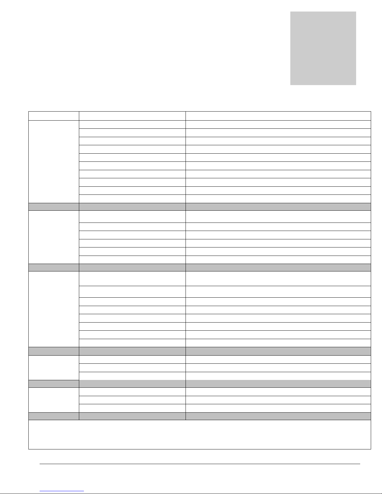
Problem
Cause
Solution
Troubleshooting
Troubleshooting –
Hydro-Force CX-15
No water Solution Hose not connected Connect Solution hose to CX-15
Spraying Ball Valve Closed on Solution Hose Open Ball Valve
Spray Gun Valve Stuck Shut Repair or replace Spray Gun Valve
Defective Quick Connect Repair or replace quick connect
Filter Screen Plugged Clean or replace filter screen
Spray Jets plugged Clean out or replace jets
Extractor Pump turned Off Turn Pump On
Extractor Pump not pumping Check pump operation & flow – Repair or Replace
Solution Hoses Disconnected Check & re-connect all connections between sections of hose
Solution Hose Plugged Check & clean out or replace hoses
Spray Bar Pressure too low Check Pump rating & operation – Repair or replace
not Spinning Flow Rate too low Check Pump rating & operation – Repair or replace
Filter Screen Plugged Clean or replace filter screen
No water spraying See previous section on No Water Spraying
Jets Plugged Clean Out or Replace Jets
Bad Swivel Replace Swivel
Not picking up
water Vacuum Hose not connected Connect Vacuum hose to CX-15
Vacuum Glide Plugged Clean out Vacuum Glide Slot
Lid off extractor waste tank Replace lid
Extractor Drain Valve Open Close Valve
Tank Full – Vac Shutoff Engaged Drain Tank
Filter clogged Clean Filter
Vacuum Hose plugged or leaking Clean Out, Repair or replace vacuum hoses
Vacuums not running Check Extractor & repair as needed
Glide Glide Worn Replace Glide
Catching on Screws on glide loose Tighten or replace screws
carpet Debris embedded in Glide Clean off or replace Glide
Handle lock Handle Lock Nut Loose Readjust Handle Lock & tighten Wing Nut
Does not Handle Lock out of adjustment Readjust Handle Lock & tighten Wing Nut
Hold handle up Handle Lock Stop Damaged Replace Main Body of CX-15
Contact your distributor for additional troubleshooting assistance, to order parts or for advice
and assistance in performing necessary repairs.
10
Page 11
Section
3
Maintenance
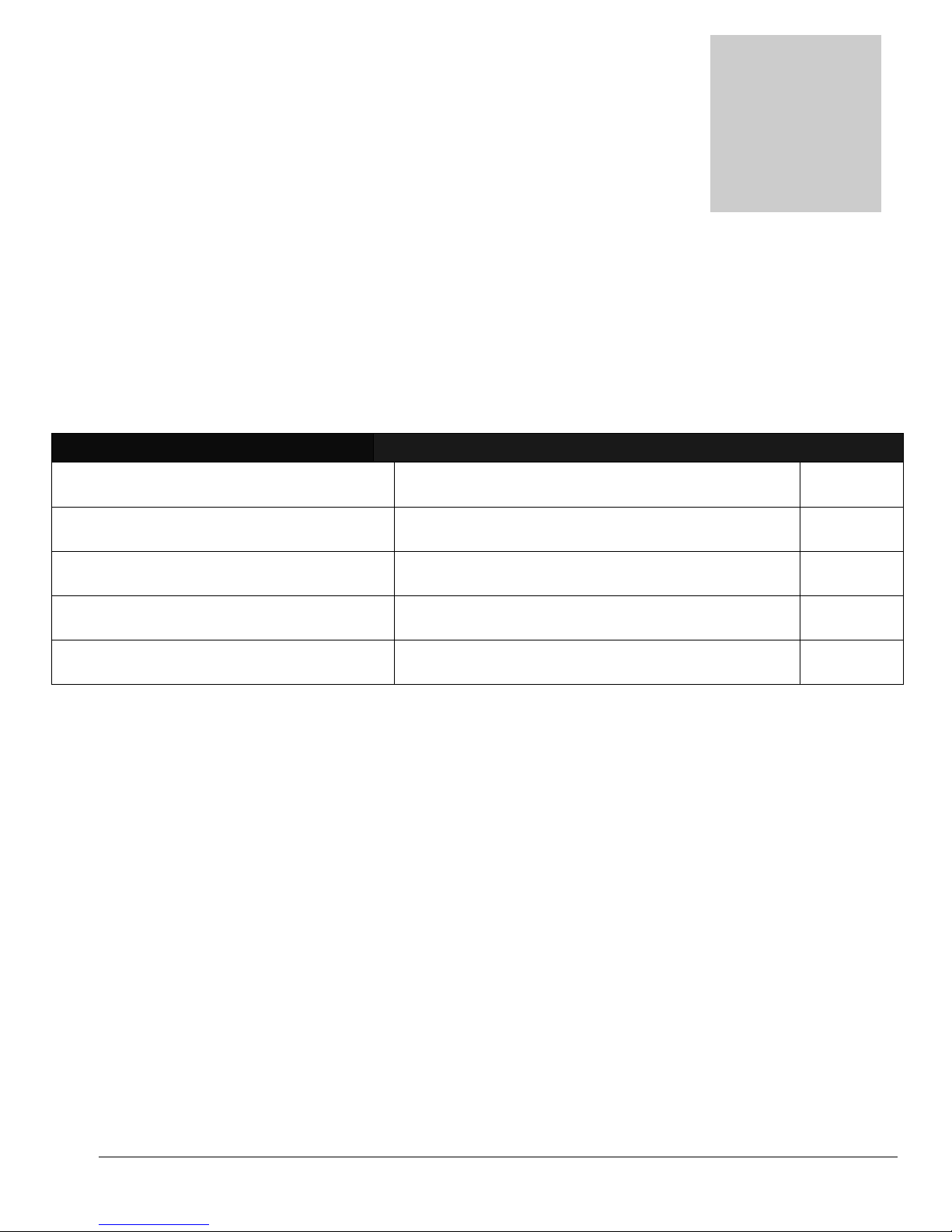
Proper maintenance is required to keep the CX-15 operating properly, prevent
downtime and to extend the life of your equipment.
WARNING: Disconnect solution hose before performing any service or maintenance
inside machine base, spray gun valve or solution filter.
OPERATION INTERVAL Page #
Cleaning the Solution Filter Once a month or more often as needed 12
Changing the Spray Bar Assembly Before each job as needed 13
Inspect Glide Plate Before each job 13
Replace Glide Plate As Needed 13
Freeze Protection Before storage as needed. 14
11
Page 12
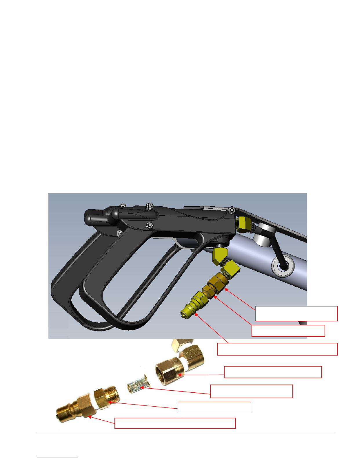
Cleaning the Solution Filter:
FILTER ADAPTER
– NA0804
FILTER BODY
– NA0802
1/4” MALE QUICK CONNECT
– AH102B
FILTER ADAPTER
– NA0804
FILTER BODY
– NA0802
FILTER SCREEN
– NA0803
1/4” MALE QUICK CONNECT
– AH102B
A dirty or clogged Solution Filter on the CX-15 will reduce the flow rate of water to the spray jets. This will
reduce the cleaning effectiveness of the CX-15 and prevent the Spray Bar from spinning at the proper speed.
The Solution Filter Screen NA0803 is in the Filter Body NA0802, between the 1/4” Male Quick Connect
AH102B and the Filter Adapter NA0804.
To remove the Solution Filter use a 13/16” wrench to hold the Filter Adapter and an 11/16” wrench to turn
the Filter Body.
Usually the filter screen will fall out or is easily pulled out of the Filter Body. If extremely dirty, you may need
to pry the filter screen out with a small flat head screwdriver.
Washout the filter screen or use an air gun to blow the debris off of the screen. If the screen is damaged it
should be replaced.
Place the Filter Screen back into the Filter Body. Apply Teflon Tape to the male threads of the Filter Body
and screw it back into the Filter Adapter and use your 13/16” & 11/16” wrenches to tighten the fittings.
Test the CX-15 operation before returning to service.
12
Page 13
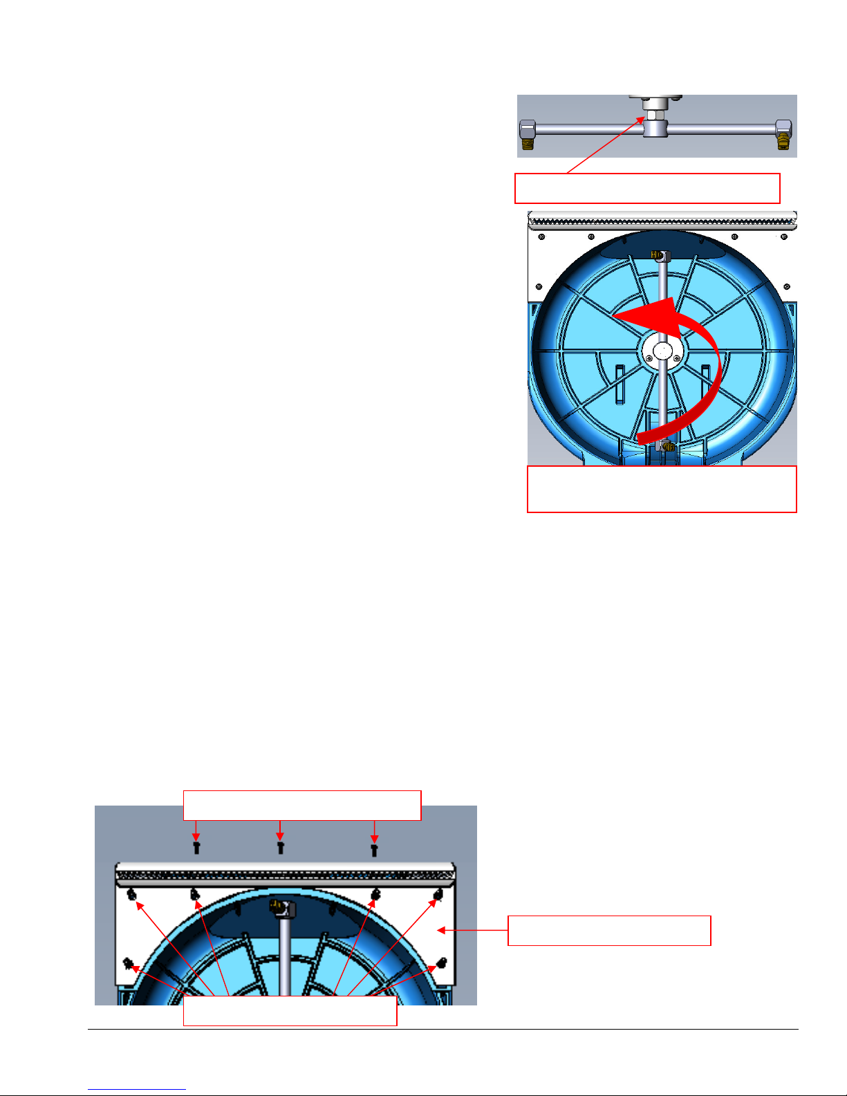
Changing the Spray Bar Assembly:
remove Spray Bar from Swivel
Six bottom screws
– NM5435
It is important that the correct Spray Bar be used for different
carpet types.
(See Spray Bar selection instructions on Page 6)
To clean different types of carpeting you will have to change
your Spray Bar Assembly.
Always disconnect the Solution Hose from the CX-15
before attempting to service or change the Spray Bar.
Use a 3/4” Wrench to hold the hex on the Swivel to prevent
the Swivel from turning. Use the heel of your hand to push on
one end of the Spray Bar to rotate the Spray Bar counterclockwise. Once it is loosened, you can then spin it to remove
it from the Swivel. The Spray Bar usually can be loosened with
just your hand, but in some cases, especially if you have not
changed the Spray Bar in a long time you may need to tap the
Spray Bar with a rubber mallet to loosen it.
Once you have selected the correct Spray Bar Assembly for
the type of carpet you are cleaning, hold the Swivel with the
3/4” wrench and spin the new Spray Bar clockwise onto the
Swivel. Use the heel of your hand to push on one end of the
Spray Bar to tighten it. Just make it snug, do not over tighten.
Hold Swivel Hex with 3/4” Wrench
Turn Spray Bar Counter-Clockwise to
Inspecting & Changing the Glide Plate:
With normal use, the Glide Plate will last for years, but as the carpet contact point for the CX-15, over time,
the Glide Plate may wear out or get damaged. Before each job, inspect the Glide Plate. Look for and remove
any debris or grit which may be imbedded in the Glide Plate surface. Check for rough edges or nicks which
could snap the carpet. A file, emery board or a fine grit sanding block can be used to smooth the Glide
surface. A worn glide may not seal as well or a damaged glide could snag the carpet.
To replace the Glide Plate, first remove the three screws from the front bottom of the CX-15 head, then flip
the tool over and remove the six screws on the bottom of the Glide Plate.
(Do not mix up the screws. The front screws & bottom screws are different.)
Place the new Glide Plate NM6004 onto the bottom of the CX-15 body assembly and replace the nine
screws. Test the CX-15 operation before returning to service.
Three front screws – NM6012
GLIDE PLATE – NM6004
13
Page 14

Freeze Protection Procedure:
Your Hydro-Force CX-15 must be protected from freezing. Freezing can cause serious damage to any
component containing water. If the CX-15 is transported or stored in freezing temperatures, the following
procedures should be performed:
Anti-Freeze Solution Method:
It is recommended that a non-toxic anti-freeze such as propylene glycol be used to freeze guard this tool.
Follow all local and federal laws regarding the disposal of any anti-freeze solution.
Pour an anti-freeze solution into the solution tank or water box of your extractor.
(Refer to your extractor operator’s manual section regarding freeze guard instructions for the extractor to
determine the best method to run anti-freeze though your extractor.)
The solution must be of sufficient dilution to prevent freezing at the expected low temperatures in your area.
Refer to the anti-freeze container label or check with the manufacturer to determine the dilution rate required.
Connect the solution hose to the extractor and the 1/4” Male Quick Connect on CX-15 tool Spray Gun.
Turn on the extractor pump. (The pressure does not have to be high enough to spin the Spray Bar.)
Hold the CX-15 over a bucket to collect the water & anti-freeze sprayed from the tool.
Squeeze the trigger on the CX-15 Spray gun to spray water from the tool and continue to spray until you see
anti-freeze being sprayed from the CX-15 jets.
Turn off the extractor pump.
Disconnect the solution hose from the CX-15.
Compressed Air Method:
Connect a compressed air hose to the 1/4” Male Quick connect on the CX-15 Spray gun.
Hold the CX-15 over a bucket to collect the water sprayed from the tool.
Squeeze the trigger on the CX-15 Spray gun to spray water from the tool and continue to spray until you no
longer see water being sprayed from the CX-15 jets.
Disconnect the compressed air hose from the CX-15.
RETURNING THE CX-15 TO SERVICE AFTER STORAGE OR
FREEZE PROTECTION:
To return the CX-15 to service, the anti-freeze must be flushed from the machine. Flush the anti-freeze out
of the machine by repeating the procedures above using fresh water in place of anti-freeze.
14
Page 15
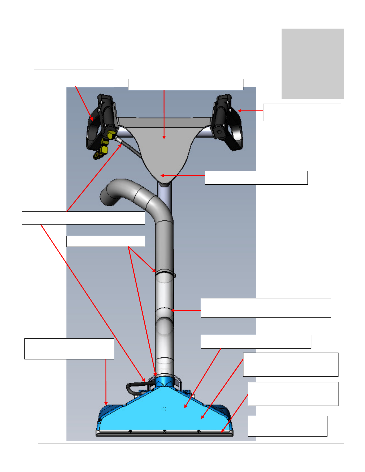
Section
3
PARTS
Gun Handle
– NA031B
DETAIL
- SEE PAGE
19
Label CX
-
15 Handle
– LBAW115H
HHHH
YDRO•
YDRO•YDRO•
YDRO•
FORCE
FORCEFORCE
FORCE
C
CC
C
X•
X•X•
X•
15
1515
15
PHY068
-
193 –
Clear Vacuum Hose
(2.1FT)
PA051
– 2” HOSE CLAMP
NM6000
– MAIN BODY
NM6002
– VAC FRONT
NM6004
– GLIDE
PLATE
SWIVEL & JET BAR
Spray Gun
– 100010
DETAIL
- SEE PAGE
20
Drawings Used to Identify Parts for your CX-15
CX•
CX•15
15
CX•CX•
1515
NM6008 – Handle Weldment
NM4088 - CX-15 Solution Hose
DETAIL – SEE PAGES 21-22
Assembly
(25 inches)
Label CX-15 FRONT – LBAW115F
DETAIL – SEE PAGES 21-22
15
DETAIL – SEE PAGES 21-22
DETAIL – SEE PAGE 23
Page 16
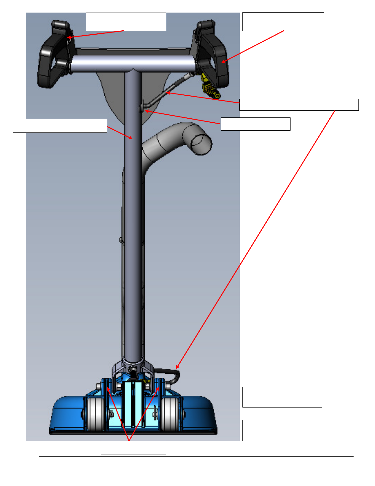
NM
6026
- CX-
15 Solution Hose
NM6000
– MAIN BODY
SWIVEL & JET BAR
Spray Gun
– 100010
DETAIL
- SEE PAGE
19
Gun Handle
–
NA031B
DETAIL
- SEE PAGE
20
NM6008 - Handle Weldment
NM5778 – Grommet
HANDLE MOUNTS
DETAIL – SEE PAGE 23
HANDLE MOUNTS
16
Page 17
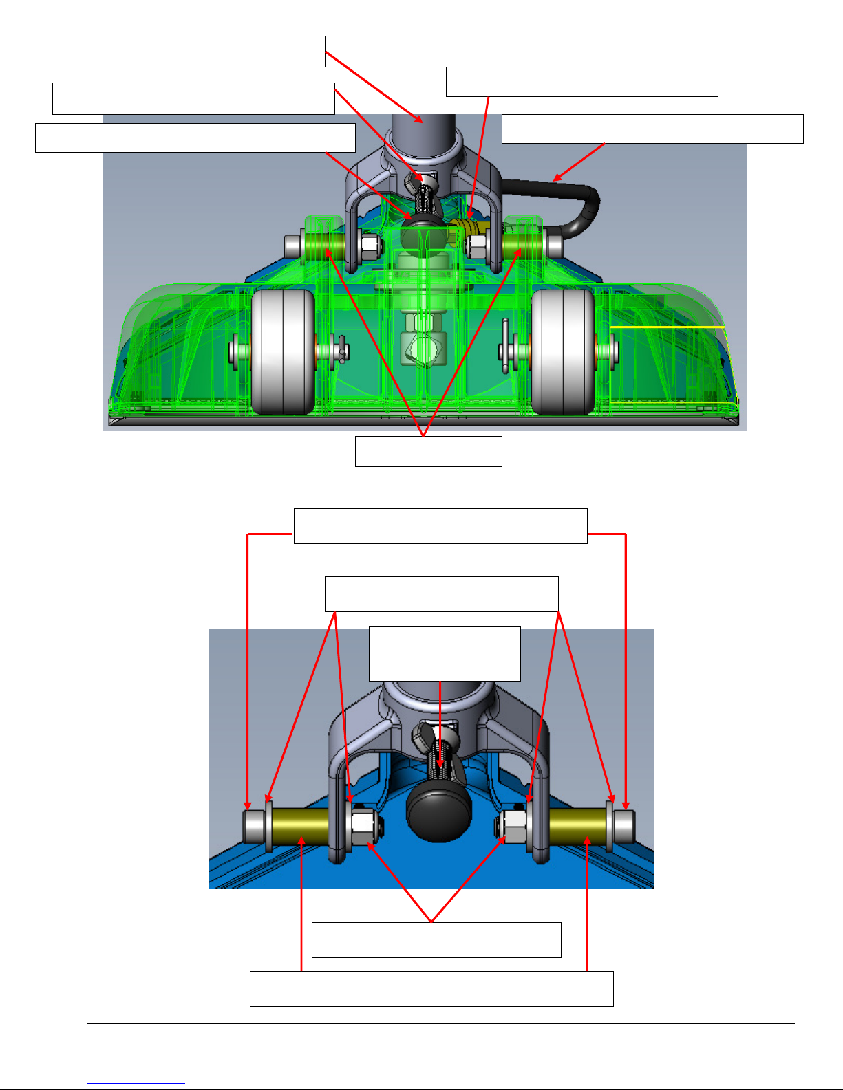
Handle Weldment – NM6008
HANDLE STOP
HANDLE STOP WING NUT – NM6010
HANDLE STOP SCREW ASSEMBLY - NM6020
NM5780 - Screw 3/8 -16 x 2" SOC HD SS
PA189 – 3/8” FLAT WASHER SS
NM4085 – NUT 3/8-16 NYLOCK SS
NM5770 – BUSHING 3/8” ID X 5/8” OD X 1” BRONZE
NA034 – 1/8” Female Quick Connect
HANDLE MOUNTS
SCREW
17
NM6026 - CX-15 Solution Hose Assembly
Page 18
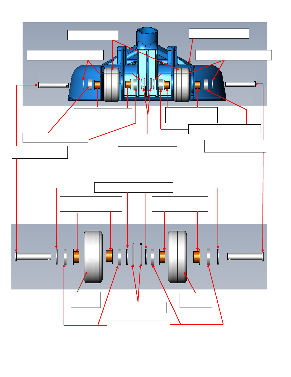
NM6016
CLEVIS PIN
NM6014 FLANGED
NM6014 FLANGED
NM6014 FLANGED
NM6006
NM6006
NM6014 FLANGED
PA189 3/8” FLAT WASHER SS
PA191 NYLON WASHER
NM6016 CLEVIS PIN
NM6006 WHEEL
BEARING
BEARING
WHEEL
NM6019 COTTER PIN
PA189 3/8” FLAT WASHER SS
BEARING
NM6019 COTTER PIN
PA191 NYLON WASHER
NM6000 MAIN BODY
PA189 3/8” FLAT WASHER SS
BEARING
PA191 NYLON WASHER
WHEEL
18
Page 19
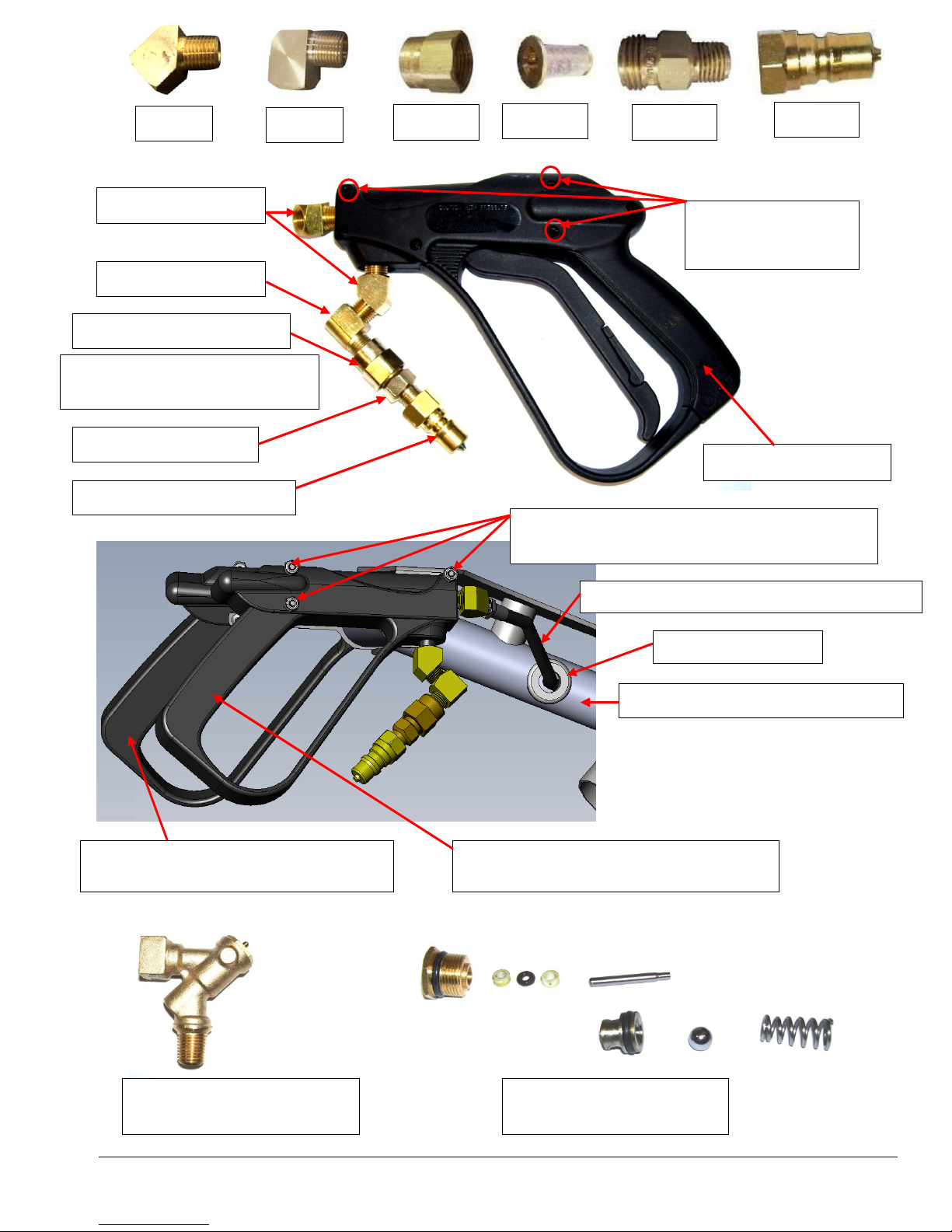
Spray Gun
– 100010
Replacement Valve
– NA033
Valve Repair Kit
– NA033A
NM4080
– Screw 10
-
32 x 1
-
5/8” SS BHSOC
Gun Handle
– No Valve
– NA031B
Filter Screen
- NA0803
Three 3/16” Hole
s
BR272
BR282
45° Elbow - BR272
90° Elbow - BR282
Filter Adapter - NA0804
(Not Shown inside Filter Body)
Filter Body - NA0802
1/4” Male QC - AH102B
(Modified for three mounting screws)
For Spray Gun 100010
NA0804
NA0803
NM4028 – Nut 10-32 Nylock
NM6026 - CX-15 Solution Hose Assembly
(Modified for three mounting screws)
For Spray Gun 100010
NA0802
drilled for Mounting
Screws
Spray Gun - 100010
NM5778 – Grommet
NM6008 – CX-15 Handle Weldment
AH102B
19
Page 20
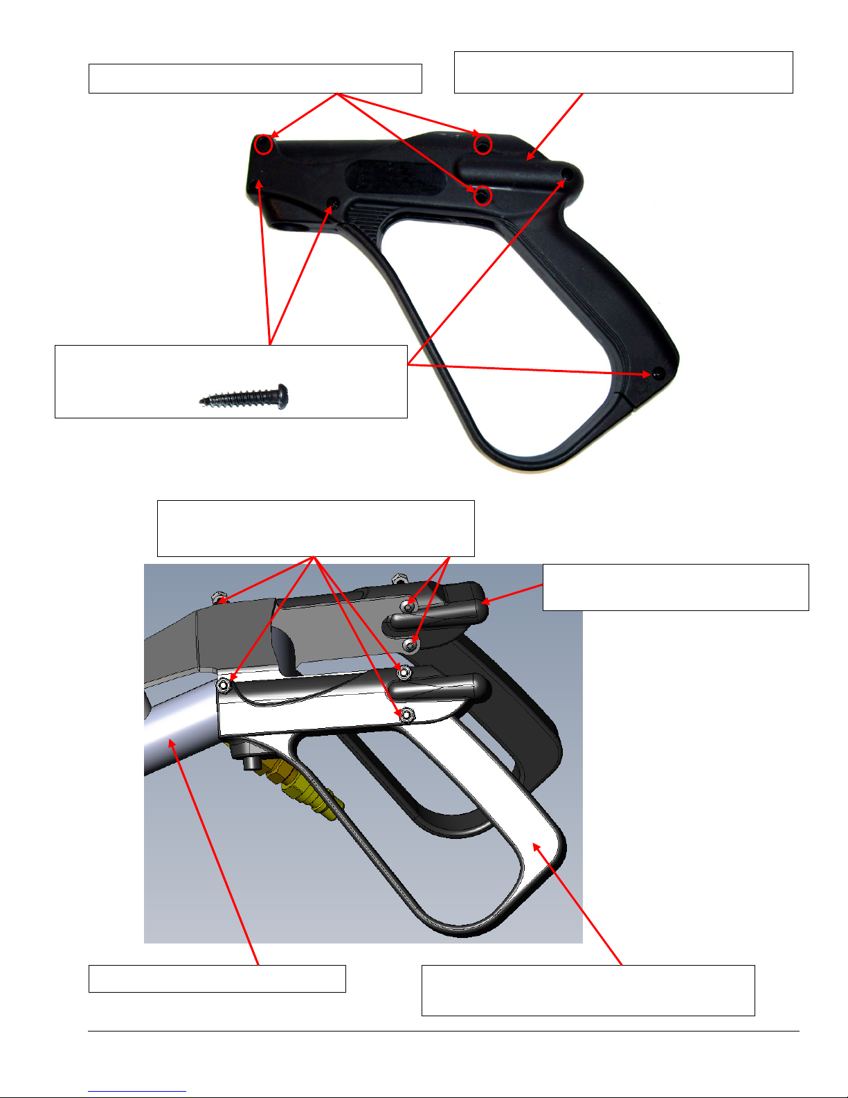
NM4080
– Screw 10
-
32 x 1-5/8” SS BHSOC
Gun Handle
– No Valve & No screws
– NA031B
(Modified for three mounting screws)
Gun Handle
– No Valve & No screws
– NA031B
NM6008
– CX-15 Handle Weldment
Spray Gun
– 100010
Three 3/16” Holes drilled for Mounting Screws
NM5629 - Screw 4mm x 20mm Self Tap PPH Black
NM4028 – Nut 10-32 Nylock
(Modified for three mounting screws)
(Modified for three mounting screws)
20
Page 21
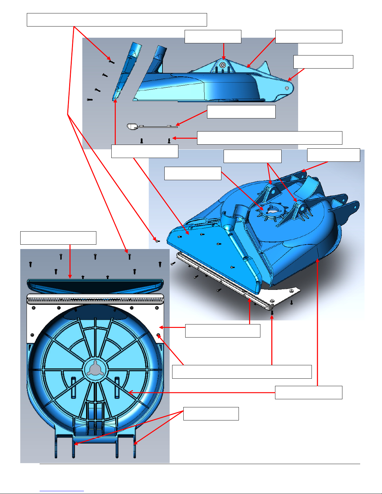
NM6012 6-18 x 7/16” Thread Forming SS Screw (Qty 9)
NM6002 Vac Front
Swivel Mount
NM6002 Vac Front
Handle Mounts
NM6004 Glide Plate
NM5435 6-32 x 7/16” PPH SS Screw (Qty 6)
Handle Mounts
NM6004 Glide Plate
NM5435 6-32 x 7/16” PPH SS Screw (Qty 6)
Wheel Mounts
NM6000 Main Body
Wheel Mounts
NM6000 Main Body
Wheel Mounts
21
Page 22
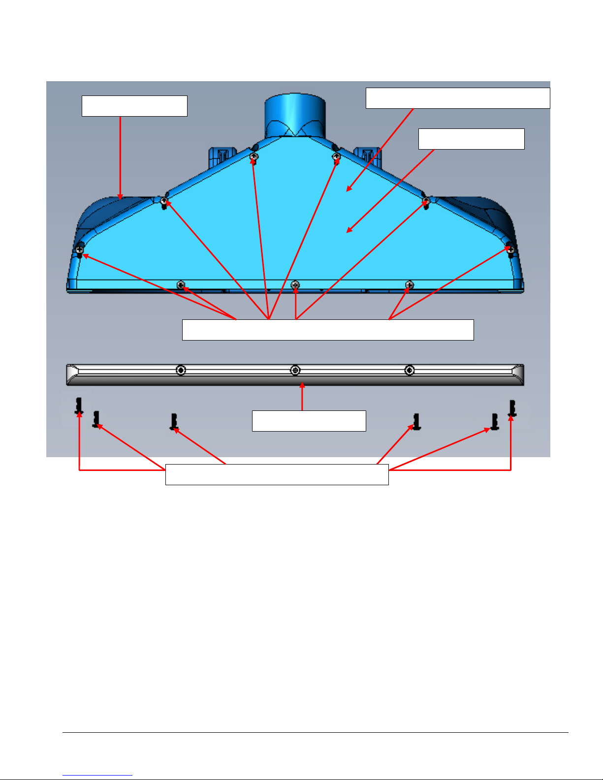
NM6000 Main Body
LABEL CX-15 FRONT – LBAW115F
NM6002 Vac Front
CX•15
NM6012 6-18 x 7/16” Thread Forming SS Screw (Qty 9)
NM6004 Glide Plate
NM5435 6-32 x 7/16” PPH SS Screw (Qty 6)
22
Page 23
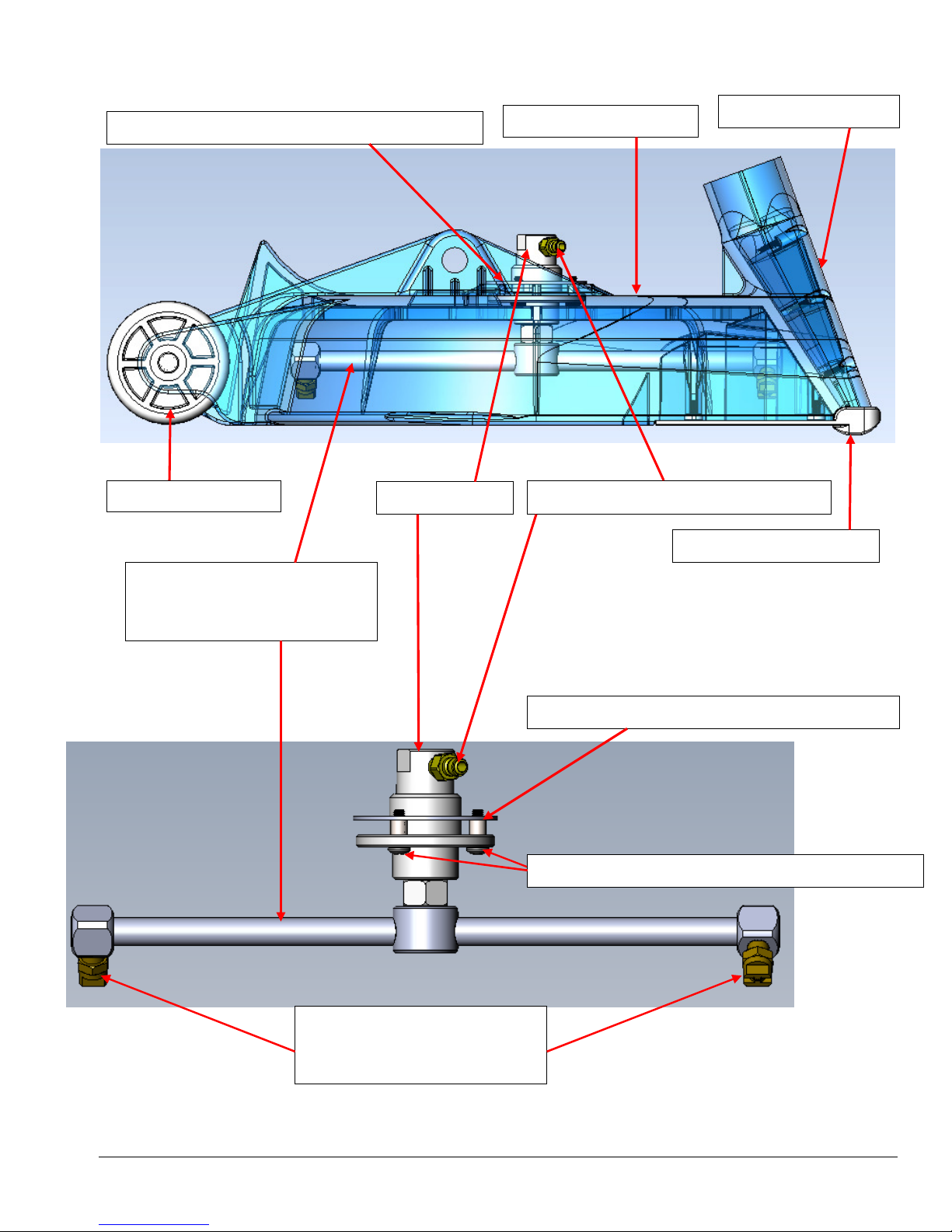
JET BAR:
SPRAY JETS 1/8” MPT SS:
NM5645 - ROTARY WASHER WITH PEM NUTS
NM6006 WHEEL
NX105 SWIVEL
COMMERCIAL – NM6024
RESIDENTIAL – NM6022
COMMERCIAL 1502 – B630
RESIDENTIAL 11002 – B344
NM6000 MAIN BODY
PKLF01 1/8” MALE QUICK CONNECT
NM5645 - ROTARY WASHER WITH PEM NUTS
NM5642 – SCREW 10-32 X .625” PPH SS (QTY 3)
NM6002 VAC FRONT
NM6004 GLIDE PLATE
23
Page 24

Section
4
Limited Warranty
Your Hydro-Force CX-15 Rotary Carpet Extractor is designed to give you years of reliable service. If a
problem should arise use the troubleshooting section in the operation manual to diagnose and correct the
problem if possible.
If you are unable to determine the cause or solution to the problem contact your distributor or Hydro-Force
for assistance.
Hydro-Force warrants the Hydro-Force CX-15 to be free from defects in material or workmanship for one
year from the date of purchase.
During the warranty period, Hydro-Force will, at its option repair or replace components which prove to be
defective. This warranty does not provide for replacement of complete units due to defective components.
Transportation or related service labor are covered for 1 year for non-wear items, e.g. stainless steel handle
and ST Nylon deck, but warranty work must be approved by Hydro-Force before work is started.
Replacement parts are warranted only for the remainder of the original warranty period.
This warranty shall not apply to defects resulting from improper operation, lack of maintenance,
unauthorized modification, chemical incompatibility, misuse, abuse or exposure to freezing temperature
conditions. It does not cover normal wear items such as filters, valve seals, hoses, jets, the Glide Plate or
other items which require replacement as a result of ordinary usage.
To obtain warranty service for the Hydro-Force CX-15, contact your distributor or Hydro-Force.
No returned items will be accepted by Hydro-Force without prior authorization. All returns must have a
return authorization number, issued by Hydro-Force, clearly marked on the exterior of the package.
Hydro-Force makes no other warranty either expressed or implied with respect to this product.
The remedies provided herein are the purchaser’s sole and exclusive remedies. In no event shall Hydro-Force
be liable for any direct, indirect, special, incidental or consequential damages.
This warranty gives you specific legal rights. You may also have other rights which vary from jurisdiction to
jurisdiction.
24
 Loading...