

Page 1
AIR WAVE
DUCT CLEANER
OPERATOR’S MANUAL
#LMANAC040 Air Wave Manual
www.hydroforce.com
Revised: 03.14.2019
Page 2
AC040 Duct Cleaner Operating Manual
TABLE OF CONTENTS
TOPIC PAGE #
Introduction 3
Standard Equipment 4
Compressor Requirements 4
Vacuum Requirements 4
Optional Equipment 5
SECTION 1: Operational Safety
Operation Safety 6
SECTION 2: OPERATION PROCEDURES
Set Up and HVAC System Cleaning 7
Special Cleaning Procedures 12
Extension Pole & Kick Plate Use 14
SECTION 3: Maintenance/ Technical
Drawings & Parts Lists 15
Warranty 23
2
Page 3

Introduction
Congratulations on your purchase of the Hydro-Force Air Wave Duct Cleaner.
Years of experience, engineering, and planning have gone into the design and
manufacturing of the Air Wave Duct Cleaner. We take a great deal of pride in
the Air Wave Duct Cleaner; our goal is no less than your complete satisfaction.
The Hydro-Force Air Wave Duct Cleaner is intended for commercial use only.
This manual will provide users with the knowledge required to properly operate
and maintain the Air Wave Duct Cleaner equipment.
All users must read and understand this manual
completely before operating the machine.
Always maintain this manual in legible condition adjacent to the Air Wave Duct
Cleaner, or place in a secure location for future reference.
Any questions pertaining to the operating or servicing of this equipment should
be directed to your nearest Hydro-Force distributor.
This manual is written specifically for the Air Wave Duct Cleaner AC040
manufactured by:
Aramsco
4282 South 590 West
Salt Lake City, UT 84123
801-268-2673
801-268-3856 FAX
www.hydroforce.com
Information in this manual is subject to change without notice and does not
represent a commitment on the part of Hydro-Force or its parent or affiliated
companies.
3
Page 4

Standard Equipment
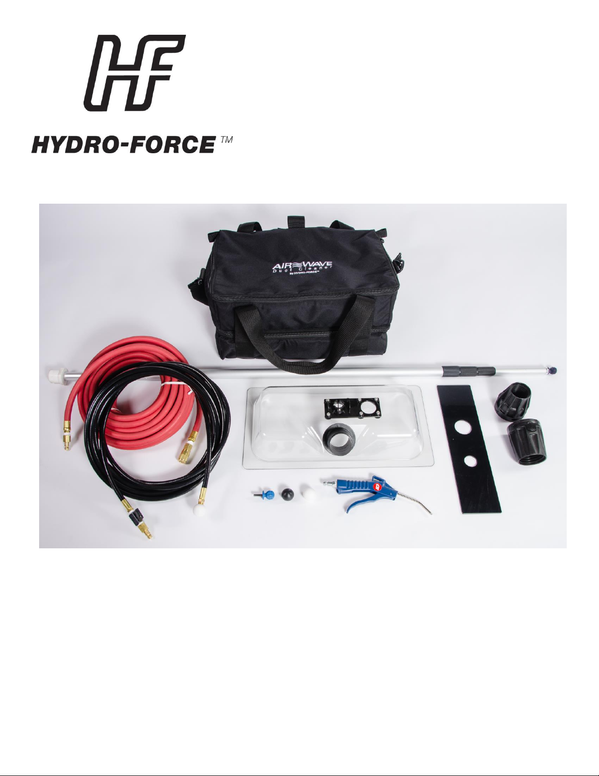
AC040 Air Wave Duct Cleaner
Standard Equipment
Vacuum Box Assembly (AC040B):
Includes: Vacuum Box (NM6100)
Dust Plug Gasket (NM6106)
Receiver Plate - Pole Mount with mounting hardware (NM6104)
2”Male Flash Cuff with 2” Male NPT with 2” Lock Nut (AH224 & NM6102)
LED Light with Adhesive Mounting Strip (AC043)
Toe Kick Adapter Plate (AC042)
Flash Cuff 2” Female for 2” Vacuum Hose (AH204)
Flash Cuff 2” Female for 1-1/2” Vacuum Hose (AH201)
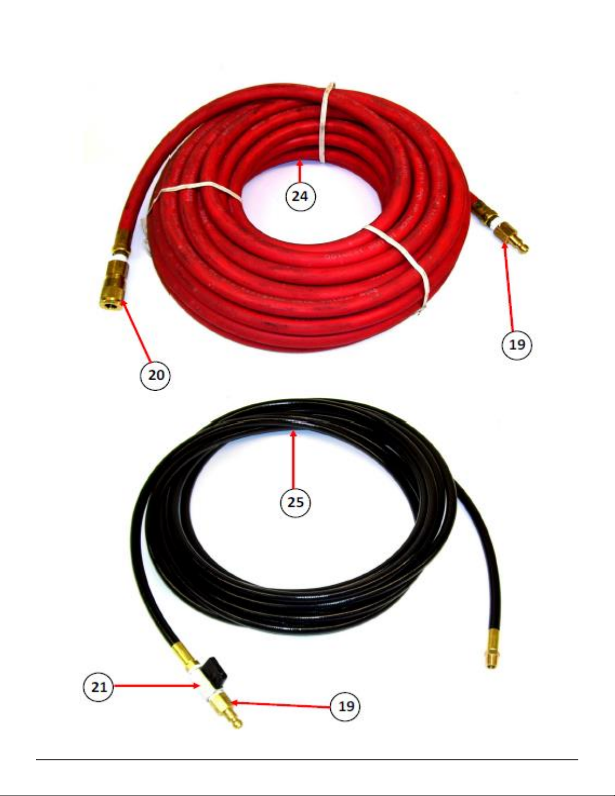
Cleaning Air Hose – 25FT. Black - Rigid 1/4” MPT ends (AH040)
Compressor Air Hose – 50FT. Red - Rubber 1/4” MPT ends (AC031A)
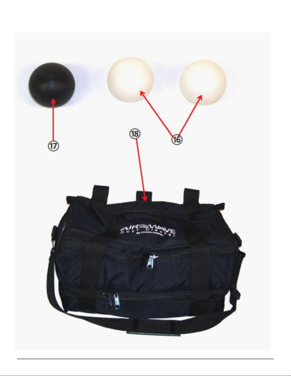
Pusher Ball – Black 1/4” FPT – Qty. 1 (NM6109)
Blaster Ball – White 1/4” FPT – Qty. 2 (NM6108)
Extension Pole - (AC049)
Extension Pole Ball End (just the ball)- (NM6110)
Air Gun – (AC047)
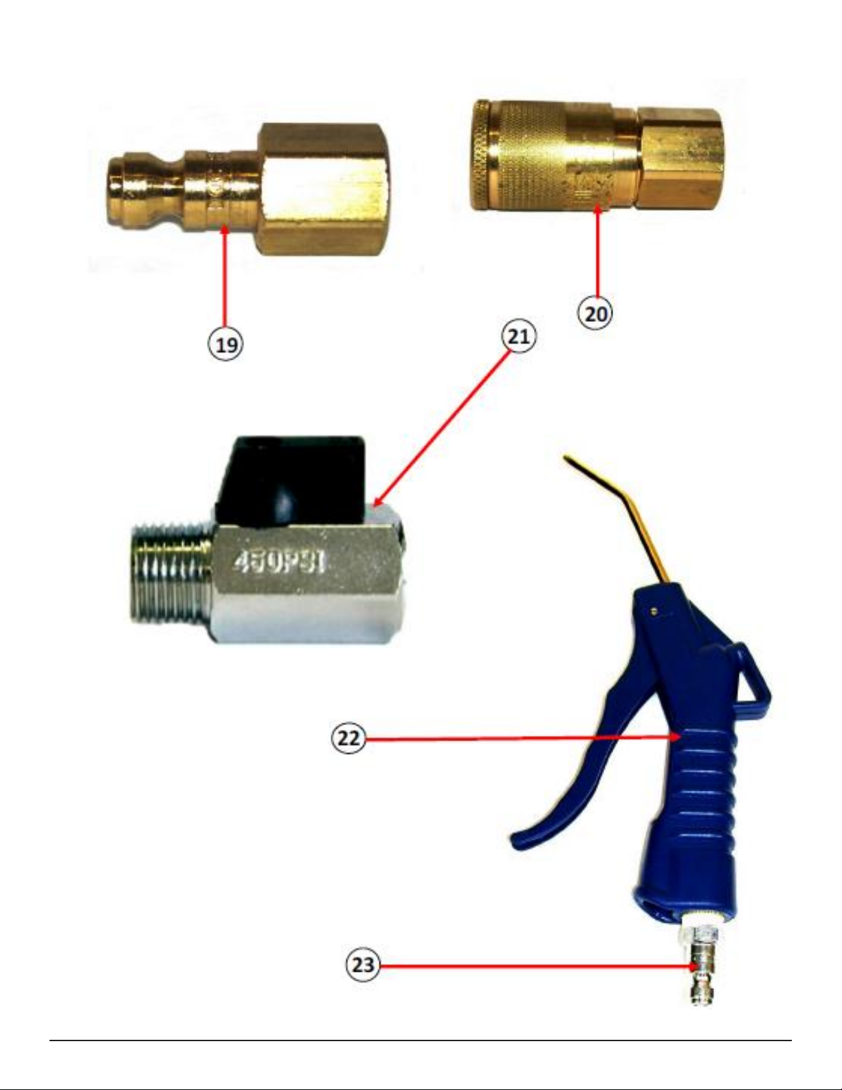
Air Shutoff Valve 1/4” FPT x 1/4” MPT (AH54)
Male Air Quick Connect – 1/4” FPT (PAF17)
Female Air Quick Connect – 1/4” FPT (PAF19)
Male Air Quick Connect – 1/4” MPT (PAF18)
Carry Bag – (AC046)
Operator’s Manual (LMANAC040)
AIR COMPRESSOR (Not included)
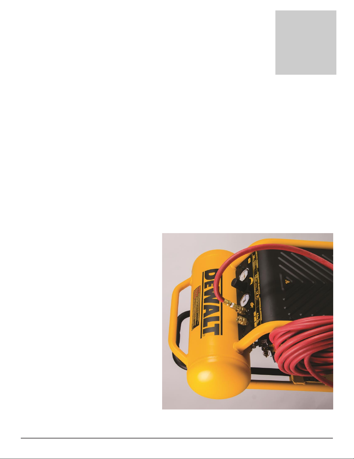
The air compressor to be used with the Duct Cleaner must meet these requirements:
Minimum 4 Gallon Air Tank Capacity
Maximum Pressure Output greater than 120 PSI
Must be able to maintain pressure for at least 10-15 seconds while cleaning each duct
Compressors with larger tanks and higher pressure will perform better but are not required.
The compressor CFM is not important as long as it meets the output pressure and tank
capacity requirements. Compressor Air Outlet should be fitted with 1/4” quick connects to
attach to the hoses supplied with the Air Wave Duct Cleaner.
We recommend the Dewalt 200 PSI air compressor, our part #MH90.
VACUUM SYSTEM (Not included)
Dry Vacuums, Portable or Truck Mounted Extractors with a minimum air flow of approximately
100 CFM air flow. Best results will be achieved using the vacuum system with the highest
powered system which maintains the highest Cubic Feet per Minute of air flow while
cleaning.
Must be setup to exhaust outdoors or have a HEPA filter if used indoors.
4
Page 5
Description
Part #
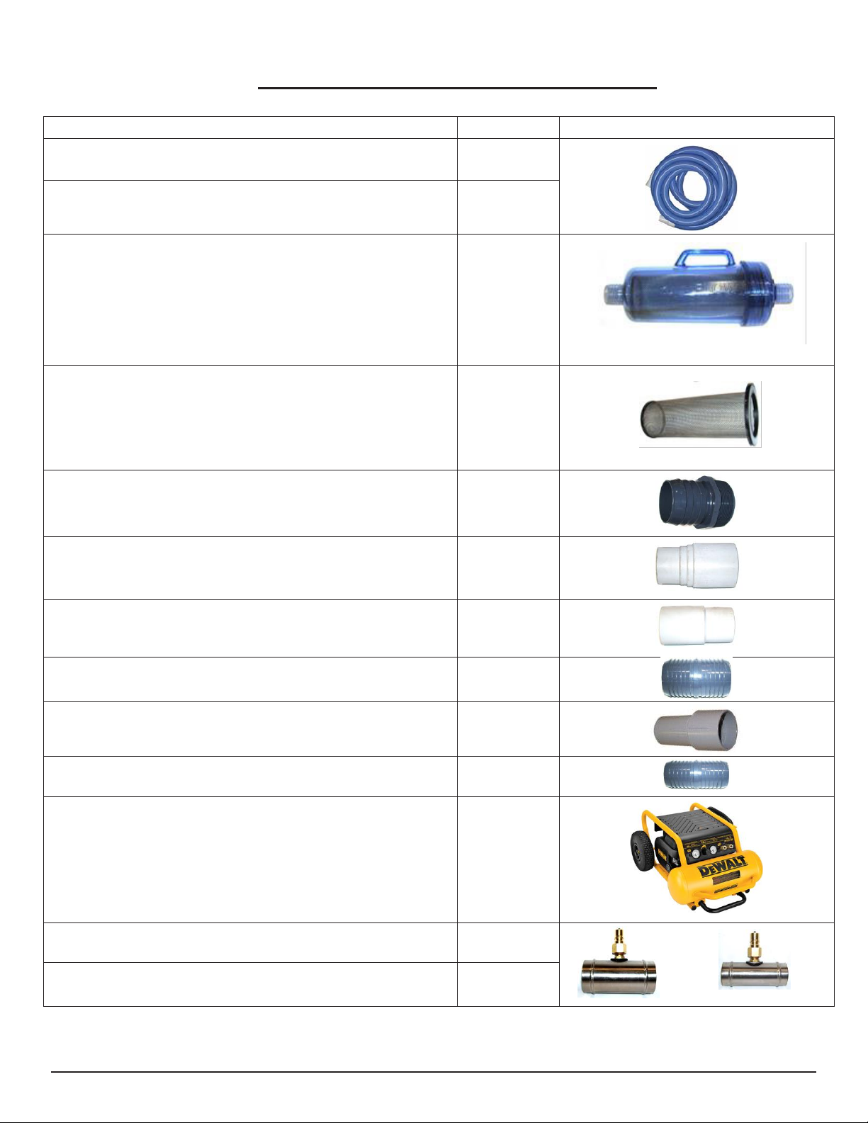
2” Vacuum Hose – 50FT. Blue with Vinyl Cuffs:
AH24
1-1/2” Vacuum Hose- 25FT. Blue with Vinyl Cuffs:
AH38BH
Hydro Filter II:
AC10
Replacement Screen for Hydro-Filter II:
AC10C
2” Hose Barb x 2” MPT PVC:
AH68
2” Hose Cuff – Vinyl for 2” Vacuum Hose
AH44
2” Hose Cuff – Vinyl for 1-1/2” Vac Hose:
AH46
2” Hose Connector PVC:
AH76
1-1/2” Hose Cuff – Vinyl for 1-1/2” Vac Hose:
AH42
1-1/2” Hose Connector PVC:
AH74
Dewalt 4.5 Gal 200 PSI Electric Air Compressor
MH90
Dry Vacuum DustDowner for 2” Hose
AH128
Dry Vacuum DustDowner for 1.5” Hose
AH127
Additional / Optional Equipment
5
Page 6

Safety
Section
1
READ AND UNDERSTAND ALL INSTRUCTIONS
BEFORE OPERATING THE AIR WAVE DUCT CLEANER.
If your vacuum system is not designed for dry soil removal you must use a Dust
Downer or other device to wet down the dust before it gets to your vacuum
system to protect your vacuums.
When using the Air Wave Duct Cleaner, it is highly recommended that your
vacuum system be exhausted outdoors. Any system which exhausts indoors
must utilize a HEPA filter, or use the Dust Downer to prevent blowing particulates
back into the environment.
Clean filters, grilles & vent covers outdoors whenever possible to avoid
contaminating the indoor air with dust & other particulates.
Wear eye protection while using the Air Wave Duct Cleaner.
Wear a dust mask or other type of respiratory protection from particulate
contaminates while using the Air Wave Duct Cleaner
Wear work gloves to protect your hands from sharp metal edges while using the
Air Wav e Duct Cleaner.
Use caution while cleaning the HVAC unit. Live electrical connections, moving
parts and sharp edges may cause injury
Turn off any pilot lights in the HVAC system and other appliances near the air
handling system before beginning the duct cleaning process.
.
6
Page 7
AIR WAVE DUCT CLEANER SET UP
Section
2
AIR HOSE & COMPRESSOR
1. Connect the red rubber air hose (AC031A) to the compressor.
2. Connect the red rubber air hose to the 25’ black air hose using the provided quick
connects. Close the Ball Valve on the air hose.
3. Plug the compressor power cord into a 15amp or 20amp 120 volt outlet and turn the
compressor on. The compressor will run approximately 2 minutes to fill the tank and
then shut off. (Other compressors may have different power requirement. Refer to
your compressor operator’s manual for power requirements.)
4. Set the compressor outlet pressure to your desired setting. The pressure setting should
be at least 120psi.
(The Dewalt compressor has a maximum outlet pressure of approximately 175psi.)
A higher pressure setting (150-
175psi) will provide a stronger
blast when the valve is first
opened but the line pressure
will drop below 60-90psi more
rapidly.
A lower pressure setting (120-
130psi) will maintain pressure
above 60-90psi for a longer
time while cleaning.
5. Connect either the Air Pusher Ball
or Air Blaster Ball to the black Air
Hose.
If cleaning the return air
system a ttach the Black Air
Pusher Ball (NM6109).
If cleaning the supply ducts
attach the White Air Blaster
Ball (NM6108).
7
Page 8
VACUUM HOSE
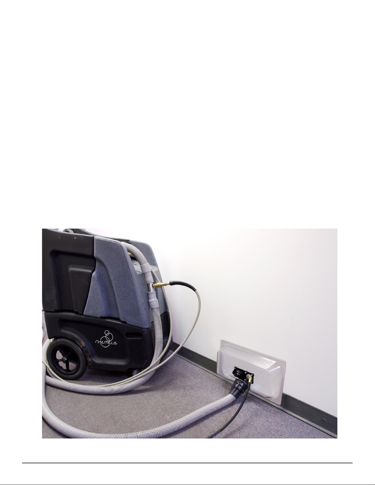
1. Attach a vacuum hose to your vacuum source. This may be either a portable
extractor, or truckmounted vacuum system. Attach a male vinyl cuff to the end of
your vacuum hose and attach to either a 1.5” DustDowner (AH127) or 2” DustDowner
(AH128).
2. Connect the DustDowner to another section of vacuum hose with male cuff attached.
This second hose will connect via female Flash Cuff (AH204) to the male Starter Flash
Cuff (AH224) on the vacuum box.
a. Note: some users like to run a long hose to the vacuum box, and then atta ch
the DustDowner with a short 3’ section so they are close to the ball valve tha t
controls water flow while working. This adds the weight of the solution hose and
brass to the end of your hose run and may make it more difficult to clean ceiling
ducts (since you have to pull both the vacuum hose and solution hose off the
floor). If most of the vents you clean are on the ground, then having the valve
closer to the vent might be preferable since you can reduce water
consumption because you don’t have to walk as far to reach the shut off valve.
3. Connect the DustDowner to your solution hose. Place a ball valve (AH54) on your
solution hose so you can control the flow of water.
8
Page 9

Operation Procedures
Section
3
STANDARD DUCT CLEANING PROCEDURE
I. Cleaning the Return Air System:
1. IMPORTANT: Before cleaning, ensure that both the heating and cooling systems function.
If there is a problem, make sure you alert the homeowner BEFORE doing any work. This
will help protect you and prevent the homeowner from blaming you for damaging their
HVAC system if there was a pre-existing condition.
2. Turn the HVAC fan ON. This will create a flow of air through the air supply and return
ducts. Ensure that the air filter is in place as this will capture the dust removed in the next
steps.
3. Remove the grilles from the air return openings and take them outside to clean. Some
grilles are hinged and not designed to be removed. If you cannot remove the grille, it
can be cleaned in place. Use your air gun (AC047) to blow the dust off the gri lle back
into the return duct.
4. Use a brush & your air gun to clean the return air duct behind the grille.
5. Attach the black Air Pusher ball (NM6109) to your air cleaning hose (AH040). The airflow
from the black Air Pusher ball pushes the dust and debris forward towards the air handler
air filter which can then be replaced or cleaned later. Connect the black cleaning air
hose to the red air compressor hose. Make sure the ball valve controlling airflow is turned
to the off position.
6. Insert the Air Pusher ball and cleaning air hose into the air return duct and open the air
valve. As you push the cleaning air hose into the return air duct the airflow will push the
dust & debris forward towards the HVAC filter. Turn the hose in a twisting motion as you
push it forward. As you move the hose, pull it back a little and then push it forward into
the duct. Once you have cleaned the entire length of the duct, close the air valve and
remove the cleaning air hose.
7. Replace the air return grille and use your vacuum system to clean up any dust and
debris remaining in the air return opening area. If you are using a truckmount or portable
extractor as your vacuum source, use a DustDowner to wet down the dust and debris in
the airflow back to the extractor.
9
Page 10
II. Cleaning the HVAC Air Filter & Fan:
1. Turn the power off to the HVAC system before beginning to clean.
2. Remove the filter from the HVAC system.
3. Remove the HVAC inspection cover to access the controls & fan. You’ll want to have a
vacuum on hand, preferably with a narrow attachment to reach into tight spaces, so
you can remove the dust that is blasted off the air handler. If you are using a truckmount
or portable extractor as your vacuum source, use a DustDowner to wet down the dust
and debris in the airflow back to the extractor.
4. Use your air gun & cleaning hose with the white Air Blaster ball attachment (NM6108) to
clean the plenum and the fan area inside the HVAC system.
5. Since your customer will have a hard time seeing many of the surfaces you will be
cleaning, it is very important that you clean the outside (visible) portions of the air
handler, grilles and registers. This will convey a strong message of thoroughness to your
customer and ensure them that you are a professional and that their ducts will actually
be cleaner when you are done.
6. Clean or replace the air filter as needed.
III. Cleaning the Air Supply Ducts:
1. Turn on the HVAC system to use the air handler’s high airflow to assist you in removing
dust from the vents.
2. Remove all the grilles in the house and use your vacuum to remove any dust on the
grilles. Use a good general purpose cleaner and towel to wipe off any dirt, oil or film on
the grille. If the grilles are especially dirty, and there is a risk of getting spots on your
customer’s carpet, take the gri lles outside to clean them.
3. Start the duct cleaning procedure at the highest point, farthest from the HVAC system.
4. Connect the white Air Blaster ball to your cleaning air hose.
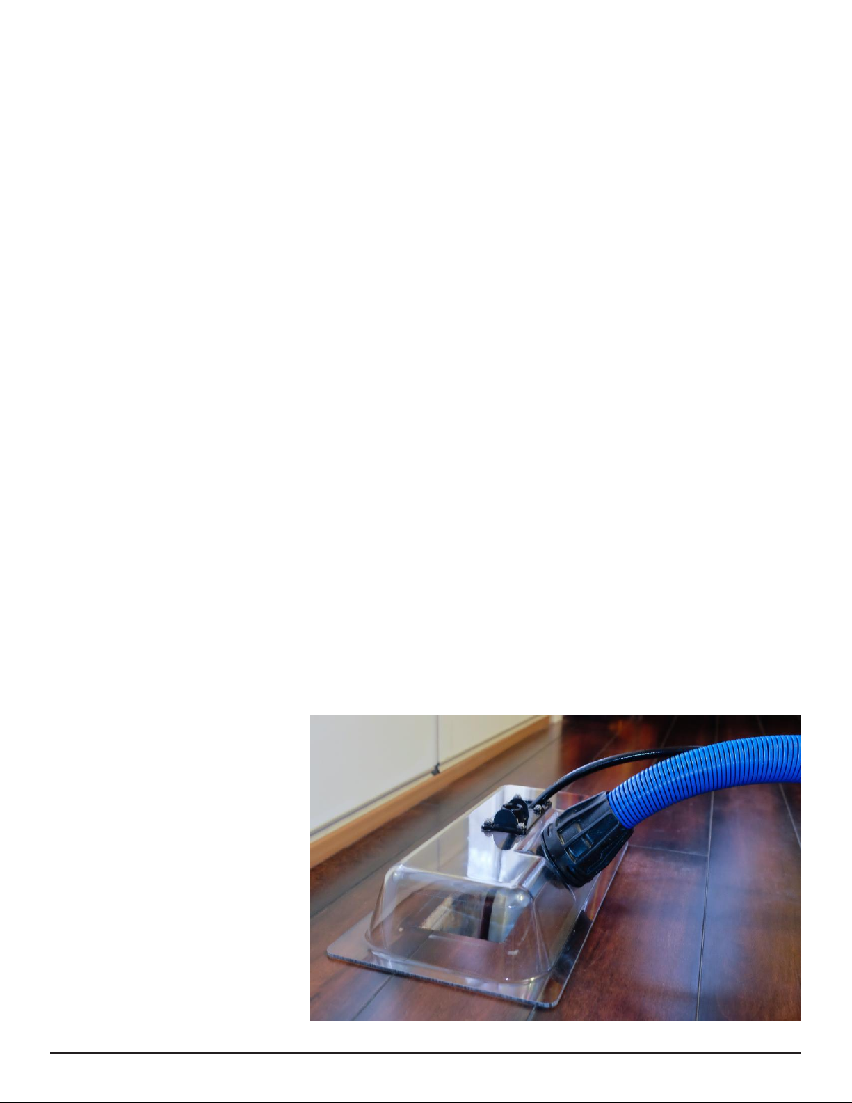
5. Turn the LED lights on in
the vacuum box so you
can more easily observe
dust removal. The LED
lights make it easier to see
the dust and debris you
remove from the
homeowner’s ducts. Show
the ho meowner the
amount of dirt being
removed from their ducts
and they’ll really
appreciate the work you
are doing.
10
Page 11

6. Connect your vacuum hose to your vacuum. Attach a Female Flash Cuff (AH204) to the
end of your vacuum hose and attach to the vacuum box.
7. Place the vacuum box over the vent opening.
8. With the air valve closed, push the white Air Blaster ball and the cleaning air hose
through the vacuum box and into the duct. Twist the hose as you push it into the duct
and continue pushing as far as the hose will go.
9. Turn on your vacuum source & open the air valve.
10. With the air pressure from the white Air Blaster Ball knocking loose the dust and debris, the
airflow from the HVAC fan, and the airflow from your vacuum hose, you should now see
the dust and debris flow into the Vacuum Box and be removed through your vacuum
hose.
11. Slowly pull the cleaning air hose back out of the duct. Pull it out some, push it back in a
little, and twist the hose as you pull it out some more and repeat the process to clean the
duct.
12. When the white Air Blaster ball reaches the vacuum box, close the air valve.
13. Disconnect the vacuum hose from the vacuum box and remove the vacuum box from
the duct opening.
14. Use your vacuum to remove any dust collected around the duct opening and any
remaining in the duct. Insert the vacuum hose down into the duct. Twist the hose as
needed to move it around inside the duct and push it in as far as you can. Pull it out
some, push it back in a little and twist the hose as you pull it out some more and repeat
the process to clean the duct.
15. Once the end of the vacuum hose is out of the duct, use the vacuum hose to clean up
the area around the duct opening.
16. Replace the vent cover and move to the closest vent and repeat the process. Work in a
pattern toward the HVAC unit until you have cleaned all of the vents and supply ducts.
IV.Final Clean Up:
1. Use your vacuum system to clean up any dust and debris remaining in the HVAC system
and vent areas.
2. Replace the HVAC system inspection cover.
3. Turn the HVAC fan setting back to its original setting for regular operation.
11
Page 12

SPECIAL DUCT CLEANING PROCEDURES
I. Mobile Home Duct Cleaning:
The different type of duct configuration in most mobile homes requires a different cleaning
procedure.
The duct system in a mobile home is constructed in an “H” shaped pattern, with the legs of
the “H” running along each side of the mobile home.
1. Start the cleaning process at the end of one leg of the duct system. Remove the vent
cover from the end vent and close all of the other vents on this leg.
2. Turn the HVAC system fan OFF.
3. Turn on the LED light located inside the vacuum box.
4. Place the vacuum box over the vent opening.
5. Connect your vacuum hose to the vacuum box. Turn on your vacuum.
6. With the air valve closed, connect the cleaning air hose to your compressor and push
the white Air Blaster Ball and hose through the vacuum box. Twist the hose as you push
it into the duct and continue pushing all the way to the end of the leg. Once you
reach the end turn the air valve on.
(An additional hose section may be required.)
7. With the combined air pressure from the white Air Blaster Ball knocking loose the dust
and debris, and the airflow from your vacuum hose, you should now see the dust and
debris flowing into the vacuum box and removed through your vacuum hose.
8. Slowly pull the cleaning air hose back out of the duct. Pull it out some, push it back in a
little and twist the hose as you pull it out some more, and repeat the process to clean
the duct.
9. When the white Air Blaster Ball reaches the vacuum box, close the air valve.
10. Disconnect the vacuum hose from the vacuum box. Remove the vacuum box from
the duct opening.
11. Insert the vacuum hose down into the duct. Twist the hose as needed to move it
around inside the duct and push it to the far end of the leg. Pull it out some, push it
back in a little and twist the hose as you pull it out some more and repeat the process
to clean the duct.
12. Once the end of the vacuum hose is out of the duct, use the vacuum hose to clean
up the area around the duct opening.
13. Replace the vent cover and move to the other side of the mobile home. Remove the
vent cover from the vent farthest from the HVAC system and repeat the process for
the second leg.
14. Remove the filter from the HVAC system.
15. Remove the HVAC inspection cover to access the controls & fan.
12
Page 13

16. Use your air gun & cleaning air hose with the black Air Pusher Ball attachment to clean
the plenum and the fan area inside the HVAC system.
17. Use your vacuum system to clean up any dust and debris remaining in the HVAC
system and vent areas.
18. Clean or replace the filter as needed.
19. Replace the HVAC system inspection cover.
20. Turn the HVAC fan setting back to its original setting for regular operation.
II. Dryer Duct Cleaning:
1. Locate the dryer vent opening on the inside and outside of the building.
2. Depending on the configuration of the dryer vent it may be easier to push the lint to
the outside from the inside using the black Air Pusher ball. Conversely, it might be
easiest to use the white Air Blaster ball from the outside and blast the lint towards you.
E.g. if the vent is located on the second story, and access is difficult, you can work
inside and push the lint to the outside and vacuum the lint that has fallen to the
ground.
3. Remove the outside vent cover if possible, or needed. Be careful not to damage the
cover.
4. If you’re working inside and want to push lint to the outside, connect the black Air
Pusher ball to your cleaning air hose.
a. Insert the cleaning air hose into the dryer vent opening.
b. Turn on the air valve and begin pushing the cleaning air hose into the dryer vent duct
using a twisting motion as you work.
c. When the cleaning air hose reaches the end of the duct, turn off the air valve and go
outside to vacuum up any lint that fell to the ground or that remains in the vent.
5. If you’re working outside and want to pull lint from the inside to the outside, connect
the white Air Blaster ball to your cleaning air hose.
a. Push the cleaning air hose into the dryer vent as far as it will go.
b. Open the air valve and slowly pull the cleaning air hose out of the dryer duct. Pull it out
some, push it back in a little and twist the hose as you pull it out some more and
repeat the process to clean the duct. Repeat the process until no more lint is being
removed from the duct. Turn off the air valve & remove the cleaning hose.
6. Clean up the lint and dust from the area around the dryer vent opening.
13
Page 14
EXTENSION POLE USE
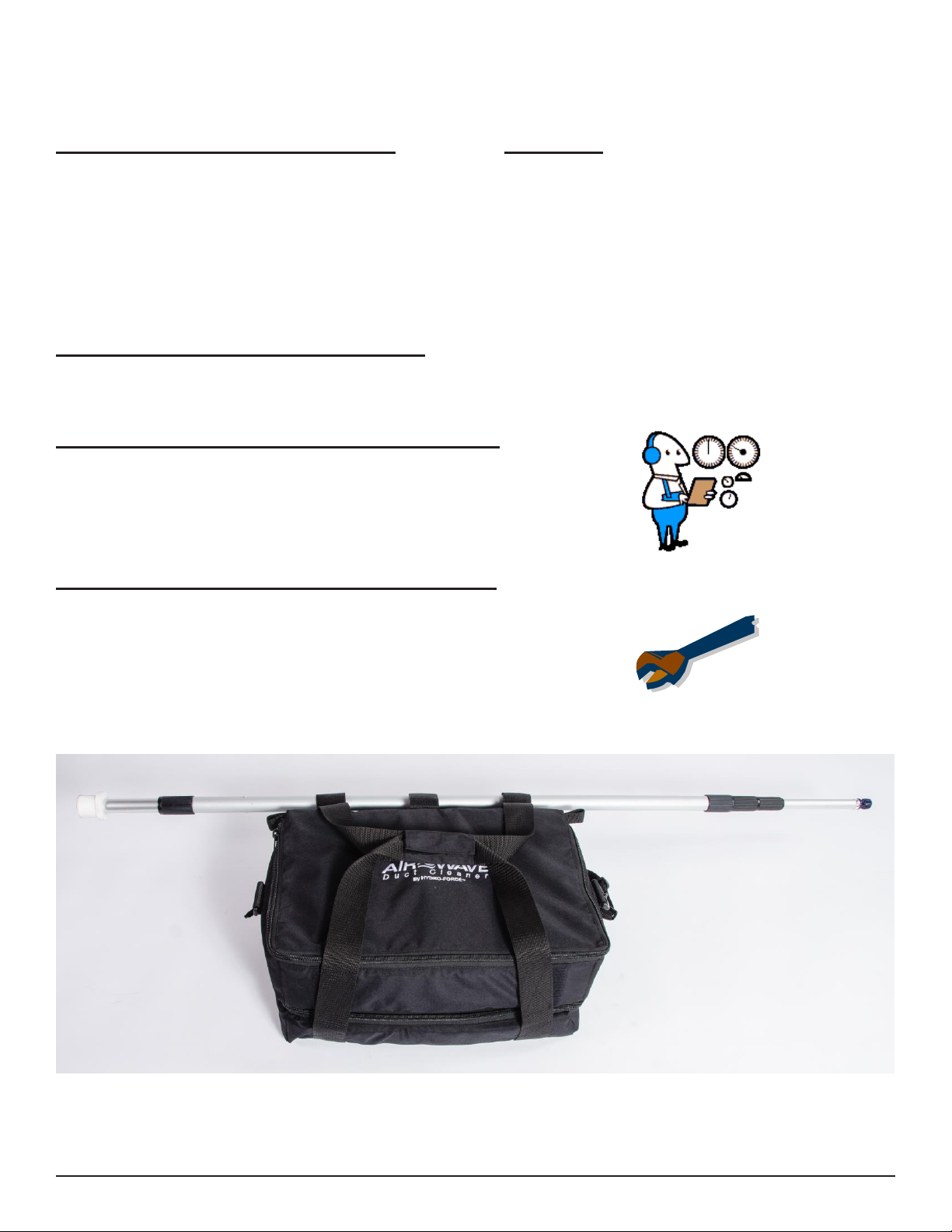
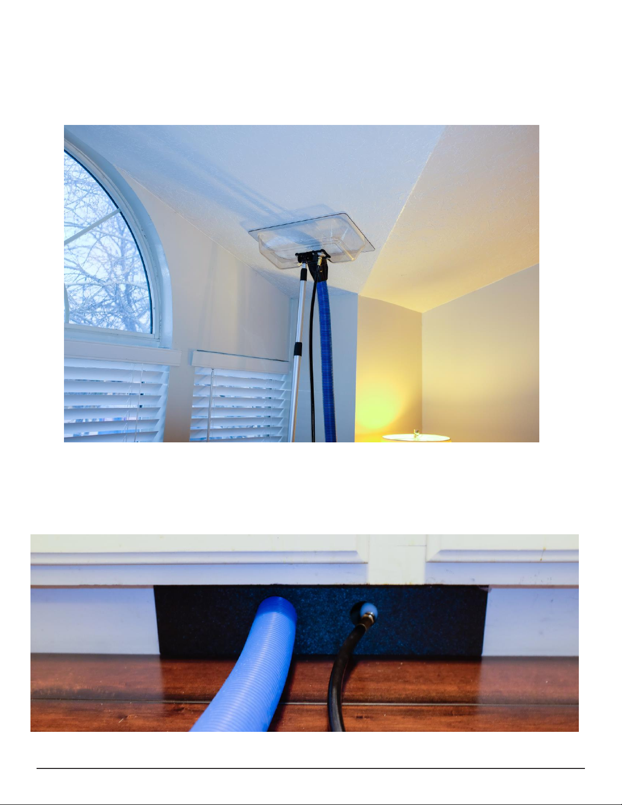
Your Air Wave Duct Cleaner comes with an extension pole to help you hold the Vacuum Box
over vent openings when these openings are located on the ceiling.
TOE KICK ADAPTER PLATE USE
Your Duct Cleaner comes with a Toe Kick Adapter Plate to help you make a seal over vent
openings when these opening are located under cabinets where there is not enough room to fit
the Vacuum Box.
14
Page 15
Key#
Part #
Description
QTY
1
NM6100
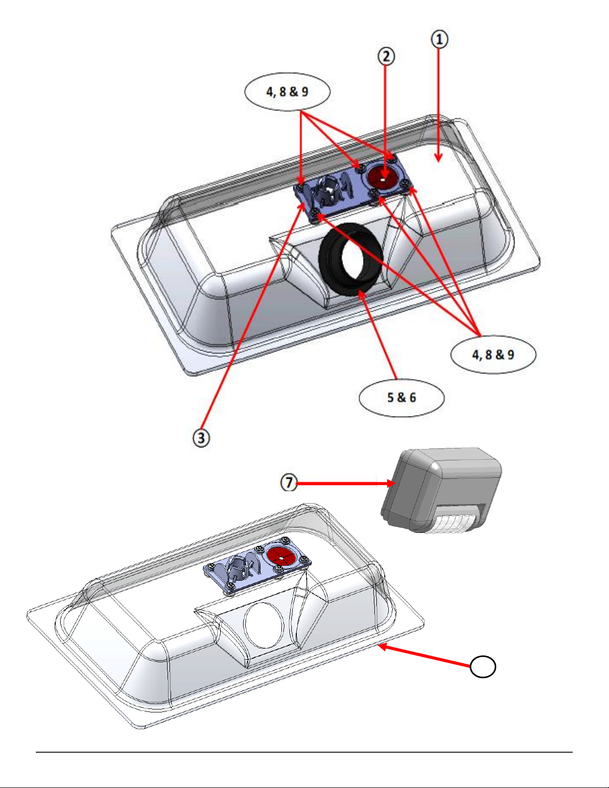
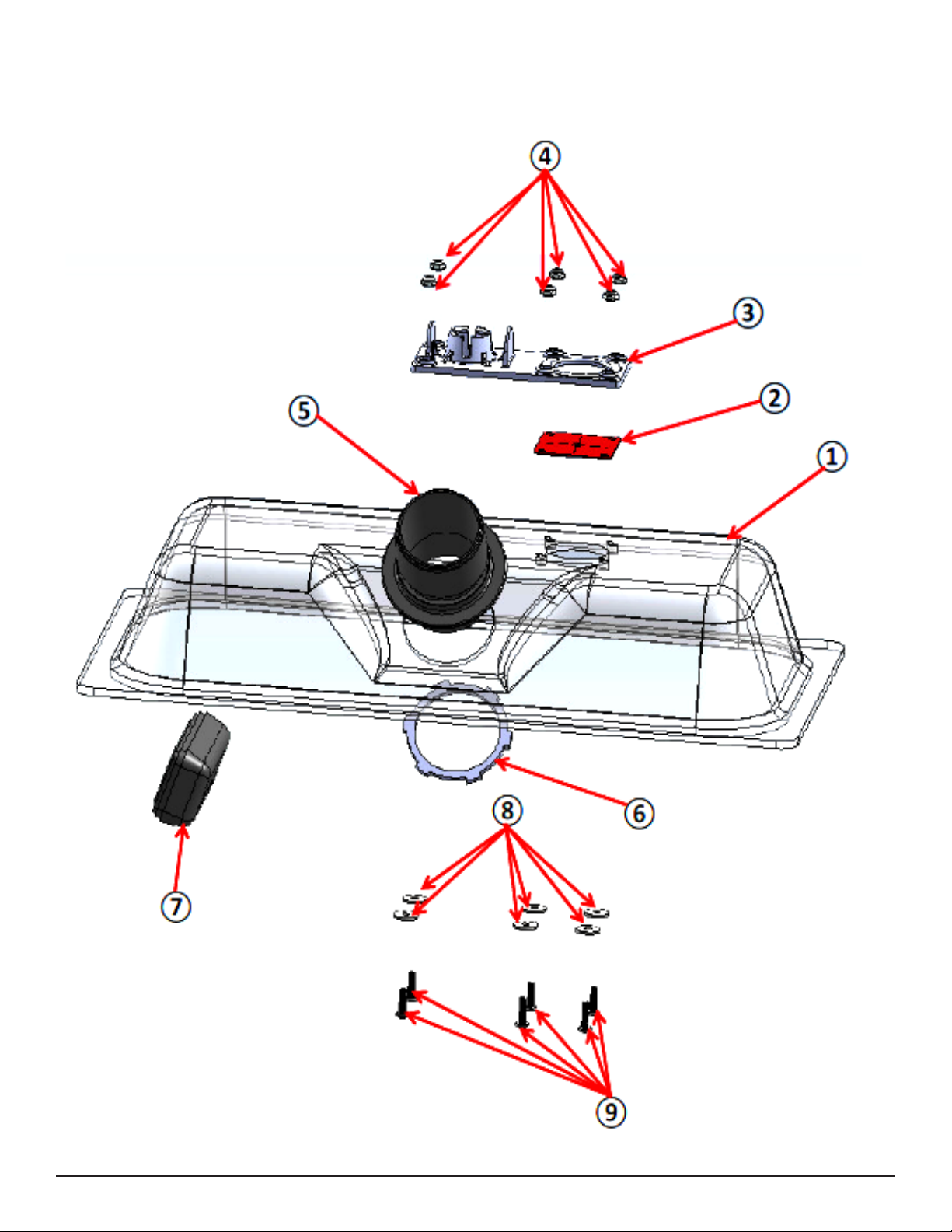
VACUUM BOX CLEAR PC – DUCT CLEANER
1
1A
VACUUM BOX ASSEMBLY (Includes Items #1, 2, 3, 4, 8 & 9)
1
2
DUST PLUG – DUCT CLEANER
1
3
NM6104
RECEIVER POLE MOUNT - PLASTIC
1
4
NM5793
NUT #8 NYLOCK
6
5
AH224
FLASHCUFF 2” MALE X 2” MPT
1
6
NM6102
NUT 2” FPT
1
7
AC043
LED LIGHT – DUCT CLEANER
1
8
NM6107
WASHER #8 FENDER SS
6
9
NM5723
SCREW 8-32 X .625” PPH SS
6
10
AC049
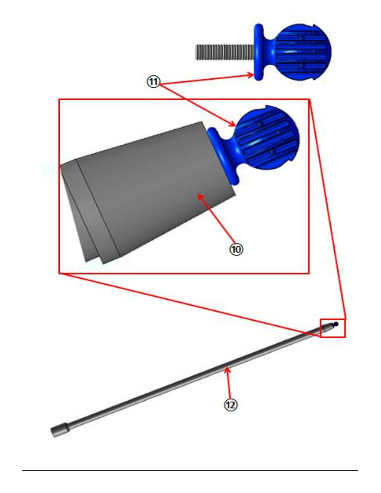
EXTENSION POLE
X
11
NM6110
BALL END – M6 THREADED
X
12
AC048
EXTENSION POLE W/ BALL END (Includes #10 & #11)
1
13
AC042
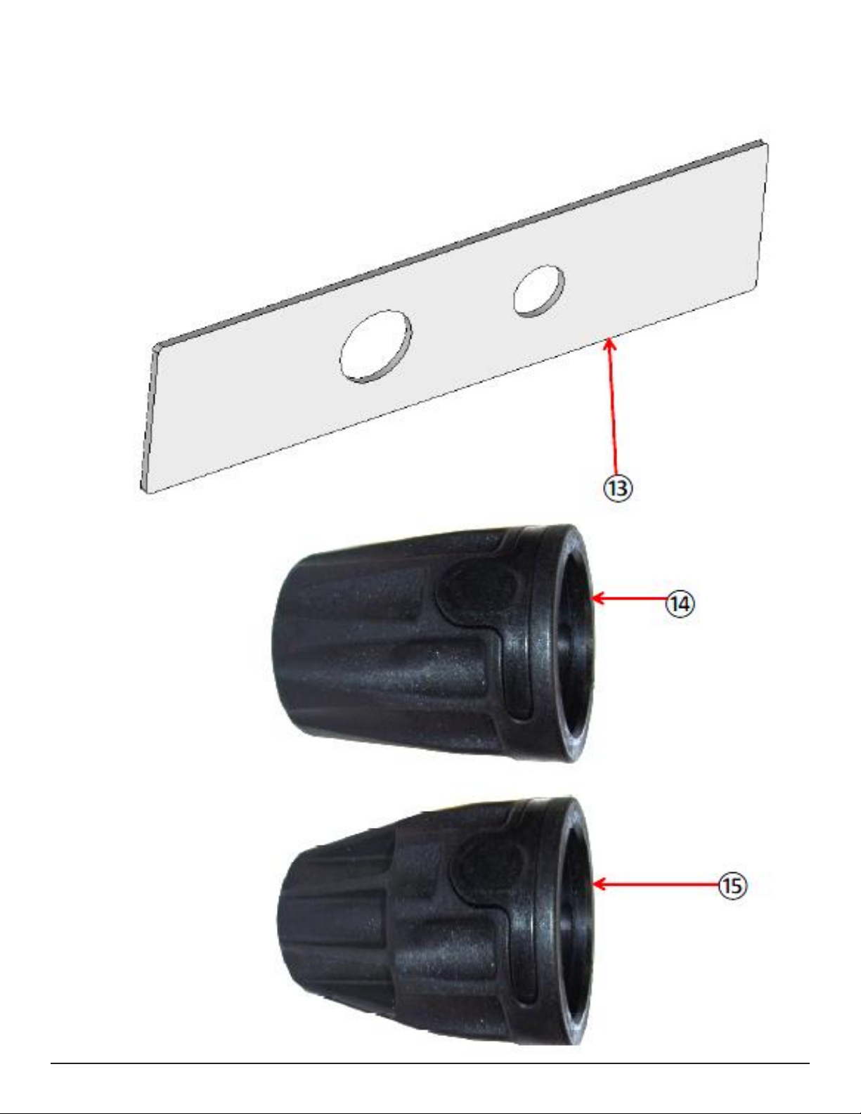
VACUUM PLATE TOE KICK – DUCT CLEANER
1
14
AH204
FLASHCUFF 2” FEMALE – FOR 2” VAC HOSE
1
15
AH201
FLASHCUFF 2” FEMALE – FOR 1.5” VAC HOSE
1
16
NM6108
AIR BLASTING BALL – WHITE 1/4” FPT
2
17
NM6109
AIR PUSHING BALL – BLACK 1/4” FPT
1
18
AC046
CARRYING BAG – DUCT CLEANER
1
19
PAF17
1/4” MALE AIR QUICK CONNECT – 1/4” FPT
2
20
PAF19
1/4” FEMALE AIR QUICK CONNECT – 1/4” FPT
1
21
AH54
BALL VALVE 1/4” MPT X 1/4” FPT
1
22
AC047
AIR BLOW GUN – PISTOL GRIP
1
23
PAF18
1/4” MALE AIR QUICK CONNECT – 1/4” MPT
1
24
AC031A
AIR HOSE RED RUBBER – 50 FT. 1/4” MPT ENDS
1
25
AH040
AIR HOSE RIGID BLACK – 25 FT. (1/4” MPT ENDS)
1
Section
3
Parts
AC041
1661-4834
15
Page 16
1A
16
Page 17
17
Page 18
18
Page 19
19
Page 20
20
Page 21
21
Page 22
22
Page 23

Limited Warranty
Your Hydro Force Duct Cleaner is designed to give you years of reliable service. If a problem
should arise use the troubleshooting section in the operation manual to diagnose and correct
the problem if possible.
If you are unable to determine the cause or solution to the problem contact your distributor
or Hydro-Force for assistance.
Hydro-Force warrants the AC040 Duct Cleaner to be free of defects in material and
workmanship for one year from the date of purchase.
During the warranty period, Hydro-Force will, at its option, repair or replace components
which prove to be defective. This warranty does not provide for replacement of complete
units due to defective components. Any costs for transportation or related service labor are
not covered in this warranty. Replacement parts are warranted only for the remainder of the
original warranty period.
This warranty shall not apply to defects resulting from improper operation, lack of
maintenance, unauthorized modification, chemical incompatibility, misuse, abuse or
neglect. It does not cover normal wear items such as o-rings, gaskets, valves, quick
connects, hoses, or other items which require replacement as a result of ordinary usage.
To obtain warranty service for the AC040 Duct Cleaner, contact your distributor or HydroForce. If the extractor must be returned to Hydro-Force or an authorized service center, the
purchaser shall prepay shipping charges for products returned for warranty service. No
returned items will be accepted by Hydro-Force without prior authorization. All returns must
have a return authorization number, issued by Hydro-Force, clearly marked on the exterior of
the package.
Hydro-Force makes no other warranty either expressed or implied with respect to this
product.
The remedies provided herein are the purchaser’s sole and exclusive remedies. In no event
shall Hydro-Force be liable for any direct, indirect, special, incidental or consequential
damages.
This warranty gives you specific legal rights. You may also have other rights which vary from
jurisdiction to jurisdiction.
23
 Loading...