

Page 1
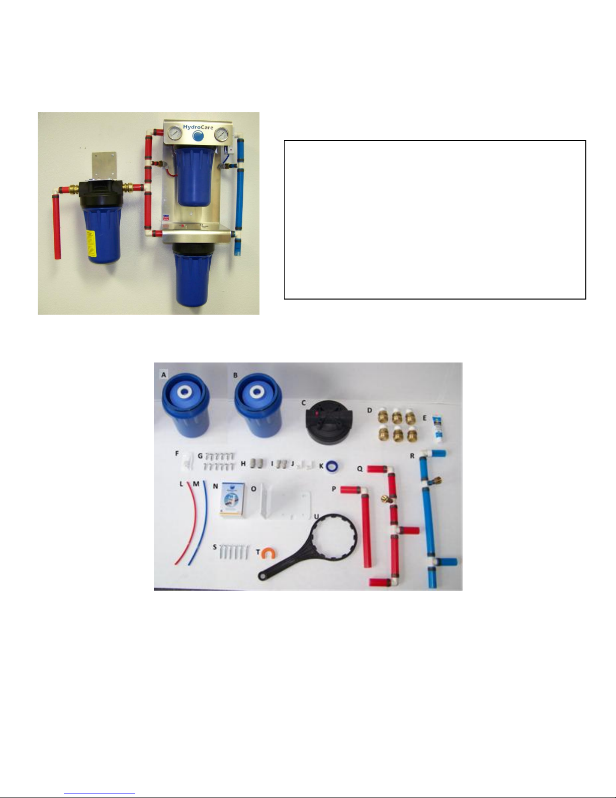
HydroCare Dual Action Water System
The HydroCare Dual Action Water System is the result of the finest
craftsmanship and the highest quality materials available. Its design
and manufacture is based on a unique modular concept which provides
higher quality water and higher flow rates while using less space and
less cost per gallon of water produced than conventional systems. The
pipe size is 1” throughout the entire unit and will adapt to household
plumbing with the use of a simple slip–on compression fitting. The
fittings recommended are available at most hardware stores and will
easily slip onto the following pipe types: PEX, Copper, or CPVC.
Other pipe types can also be adapted to the HydroCare Dual Action
Water System with the use of an additional adapter. These fittings are
available at most hardware stores. Installation must comply with any
existing state or local plumbing codes.
Installation, Use & Care Guide
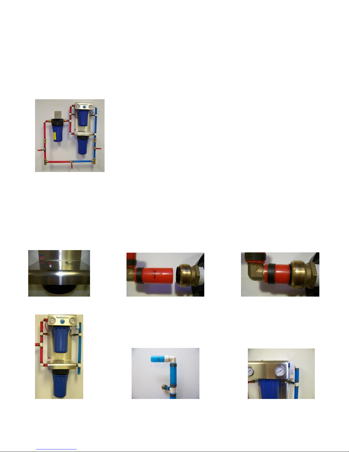
Parts & Material Included
A. 2 Canisters w/ Inserts H. 2 John Guest Males O. Wall Mount Bracket
B. Canister w/ Pre-filter Insert I. 2 John Guest Females P. Inlet Pipe Assembly
C. 3 Canister Heads J. 2 John Guest Adapters Q. Iron to DAWS Pipe Assembly
D. 6 SharkBites® K. Teflon Tape R. Outlet Pipe Assembly
E. Pipe Thread Compound L. ¼” Red Tube S. 6 Wall Mount Screws
F. Silicon M. ¼” Blue Tube T. SharkBite® Removal Tool
G. 12 Lag Bolts N. HydroCare U. Canister Wrench
Page 2
Tools & Parts Needed
■ Adjustable Wrench
■ Flathead Screwdriver
■ ½” Nut Driver
■ Optional ByPass Assembly. Obtain kit by
contacting location where your HydroCare
DAWS was purchased.
Installation Requirements
■ Properly tighten all fittings to ensure a leak-free assembly.
■ The system should be located after connection for the outside hose bibs,
sprinkler system(s), and/or irrigation line(s). These lines should be left
untreated.
■ Install in a location that is not susceptible to freezing temperatures as damage
to the Canister could occur.
■ Install away from direct sunlight as prolonged exposure to light can weaken
plastic components.
■ The system needs to be mounted to a solid surface using wall mount screws
(cover is drilled for 16 inches on center). For additional stability, use 2 X 6
board connected to studs and mount unit to boards.
■ Allow a minimum of 4” clear space below unit to facilitate insert change.
■ You may consider an optional ByPass Assembly with additional shutoff
valves for convenience when changing the inserts.
ByPass Assembly
Installation Instructions
Unscrew the Heads from the Canisters. Liberally apply the pipe thread compound to the taped SharkBites®. Place the SharkBites®
into the Canister Heads. Do not over tighten. Position the Heads with the Red Pressure Release Button on the left which is the Inlet
side. Attach the 10” Canister Heads to the Mounting Cover using the lag bolts. Position the cover to line up the bolt patterns and the
pressure release buttons (See Figure 1). (DO NOT OVER TIGHTEN)
Line up the Ion to DAWS Pipe Assembly to insert the pipe. Press the pipe in up to the mark on the pipe (See figure 2 and 3). Repeat
for the Blue Outlet Pipe Assembly. The Red Pipe will go on the left (See Figure 4).
Figure 1 Figure 2 Figure 3
Figure 4 Figure 5 Figure 6
- 2 -
Page 3
5. Plug the low voltage cable into the unit and connect
the transformer to the main power supply. Plug in and
test to see if red light glows brightly then unplug.
4. Withdraw the split pin.
1. Screw the mounting bracket
to the pipe with a screwdriver
2. Push the top section firmly
onto the bracket.
3. Clip on the lower section.
There are two ¼ inch tubes
included, 1 Red, 1 Blue.
They are push-in fittings.
The tubes are marked (See
figure 9). Insert the Red and
Blue tubes by pushing into
the fittings up to their marks
(See Figure 10). Attach the
tubes to the gauges as shown
here.
■ Attach the Iron Canister Head to the Wall Mount
Bracket.
■ Insert Iron to DAWS Pipe Assembly into the
Canister Head.
■ Mount Wall Mount Bracket.
■ Insert Outlet Pipe Assembly into Canister Head.
■ Hand screw Canisters into their Heads. Use Canister
Wrench to make snug.
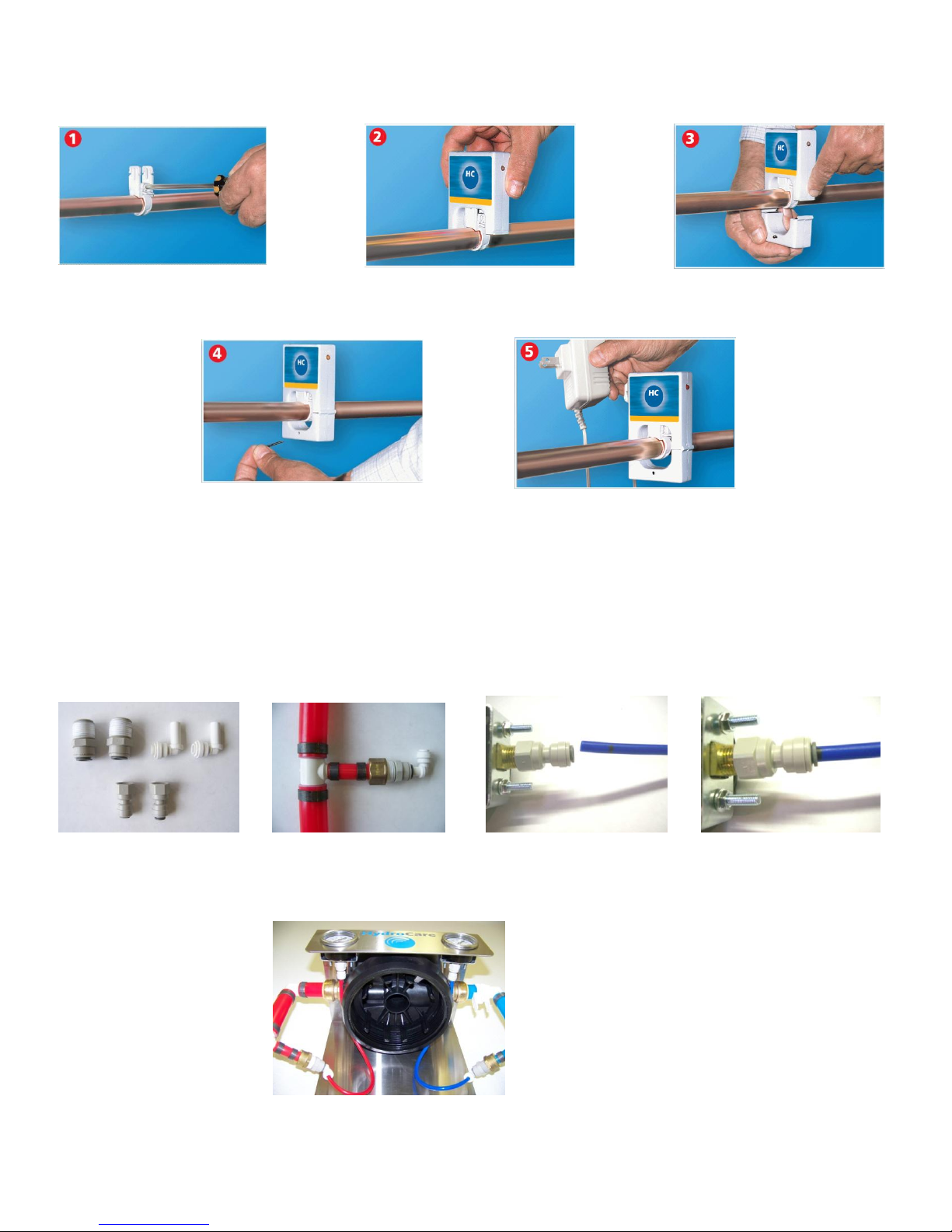
Locate the tape mark at the elbow (See figure 5). This is the location for the HydroCare strap connection. Attach the HydroCare Unit
with the light facing away from the pipe assembly (See Figure 6).
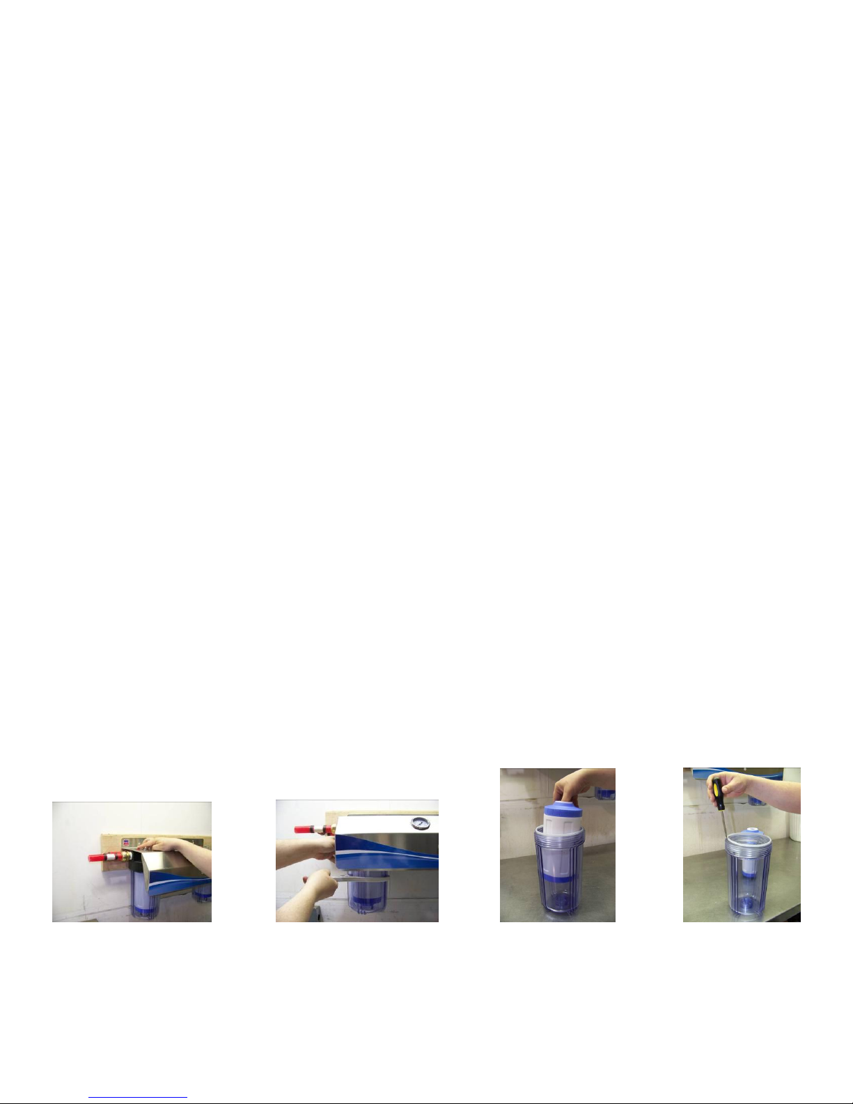
After the Cover is attached, turn the system over. Wrap the John Guest threads 4 times around with Teflon tape. Wrap the threads on
the pressure gauges in the same manner. Attach ½” male fittings into the brass adapters on both the Red & Blue pipe assemblies and
attach the adapters to the ½” male fittings (See Figure 8). Attach the ¼” female fittings into the pressure gauges (See Figure 9).
John Guest Fittings
Two ½” males w/ adapters Figure 8 Figure 9 Figure 10
Two ¼” females
- 3 -
Page 4
Connection Instructions
1. Installation of Water ShutOff Valve is recommended for filter changes and for emergency shut off of water.
2. Plug in the HydroCare. You should be able to see the light through the sight cover. (You may need to align the HydroCare
for best view of the light).
3. Turn off your water supply.
4. Turning off your water heater is recommended.
5. Release water pressure by opening a faucet.
6. Attach water source to the Red pipe (Inlet). Existing Inlet pipe size smaller or greater than 1” will require an additional
adapter.
7. Blue is for the purified water to your home (Outlet). Existing Outlet pipe size smaller or greater than 1” will require an
additional adapter.
8. You may now turn your water on. Go slowly and check for leaks.
9. Check and note your pressure gauges. Inlet pressure should not exceed 70 psi. If you exceed 70 psi, then you must install
a pressure regulator set at 65 psi or less.
10. Turn your water heater on.
11. Close open faucet.
Insert Replacement Instructions
1. A pressure differential between Inlet and Outlet Gauges of 0 to 5 psi is normal. Pressure loss of 10 psi or more indicates time
to change your Inserts. Depending on your water quality, your Inserts should last between 6-12 months
2. Shut off main water feed to filtration unit or use ByPass.
3. Open a cold water faucet.until water stops running. Leave faucet open.
4. Push red buttons on top of filter housings to relieve pressure (See Figure 11)
5. Place a water receptacle under the unit. ie. A bucket or a pan.
6. Use filter wrench, turning wrench to the left, to unscrew housing from lid (See Figure 12). Please note that they will weigh
approximately 11 lbs. each at this time.
7. Remove bottom of housings by lowering straight down.
8. Remove used inserts from housings by placing your thumb in the center and your fingers on the outside of the insert (See
figure 13).
9. Empty the water into your receptacle.
10. Use a blunt edge. ie. butter knife or flathead screwdriver to remove o-rings (See Figure 14).
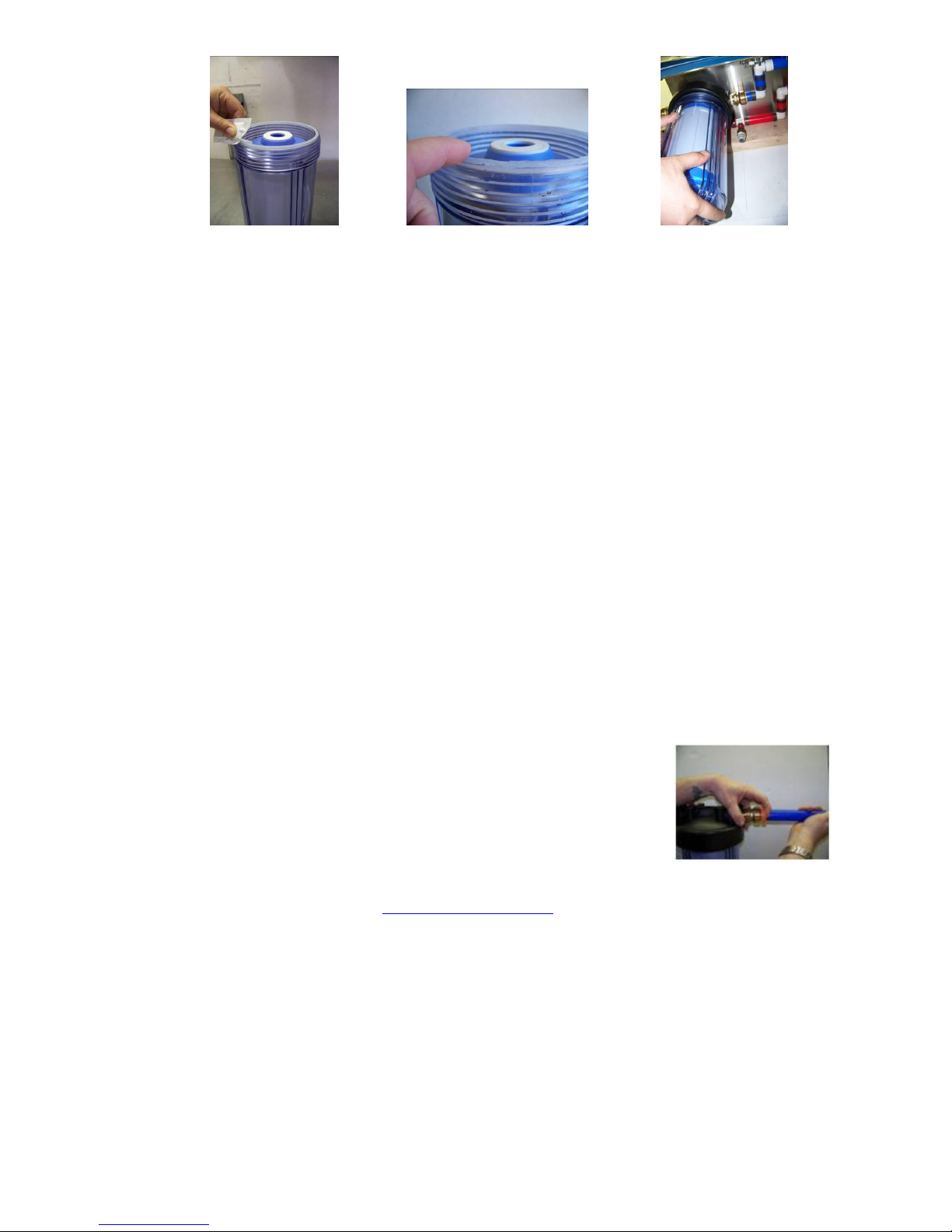
11. Open the silicon packet provided and liberally apply to the o-rings surface. Replace the o-rings and apply silicon to the
circumference of the top of the o-rings. It is important that there is no dry surface on the o-rings (See Figures 15 & 16).
12. Unpack the new inserts.
13. Place the new inserts into the housings top up. The top is where the white rubber grommet is.
14. Place housings, one at a time, level up to housing lids (See Figure 17). Turn them to the right until hand tight.
15. Use filter wrench until snug.
16. Slowly turn your main water feed back on until water returns to your open faucet.
17. Check for leaks.
18. If you do have a leak or a drip, repeat steps for applying silicon.
Figure 11 Figure 12 Figure 13 Figure 14
- 4 -
Page 5
1. Push the clip against the release collar. Once the clip release collar is fully depressed,
pull the tube. DO NOT pull the tube until you have fully depressed the release collar.
2. If the tubing is disassembled from the fitting, check both the fitting and tube end for
damage. The fitting should be free of damage, dirt, and foreign objects.
Figure 15 Figure 16 Figure 17
Troubleshooting Guide
■ If water leaks at fittings: Tighten slightly more until leak stops.
■ If leaks persist: Shut off water at the house water supply shutoff valve, remove threaded fittings, reapply Teflon tape in a clockwise
direction and screw back onto head assembly
■ If there are leaks around Canister Head: Shut off water at the house water supply shutoff valve. Unscrew the canister from the head,
and check the o-ring to make sure its seated flat along the edge of the canister. Re-lube the o-ring, and hand tighten the canister. If the
drip persists, use the provided filter wrench to tighten slightly. Make sure to check the o-ring for cuts, burrs, and any other
imperfections. Note: make sure the entire surface of the o-ring is well lubed. This is key to the water tight integrity of the filter
canister.
■ If there is a leak where the tubing is attached to the gauge: Relieve the system pressure, and check to see if the tubing is inserted all
the way to the mark. If the drip persists, remove the tubing, and check for burrs and obstructions then reinsert to the mark.
■ If there is no water in the house: Check the inlet gauge on the system. If the pressure coming into the system is normal, this
indicates that your filters are clogged. Simply replace the filters according to your owner’s manual. Note: If you have no re placement
filters on hand, remove the filters until they can be replaced.
■ If your water pressure is low, or constantly dropping: This indicates that the filters need to be replaced.
■ If you notice a bad taste or odor, but still have plenty of water flow: This indicates that the media in the filters is saturated, and
needs to be changed immediately.
■ Should you ever have a problem with an o-ring, a spare set of replacement o-rings has been provided.
■ How to use the Shark Bite removal tool:
■ If you have further questions after thoroughly reading this guide: The HydroCare Service Department can be reached Monday –
Friday, from 9am – 4pm PST at 253-887-7625 or at [email protected].
Note: Fill out the enclosed Warranty Card and mail. Your serial number is located on the underside of the Cover. Make appropriate
entries on the Maintenance Card provided (ie. date installed and dates filters are changed). Keep attached to the system and updated
when needed.
- 5 -
 Loading...