

Page 1
®
ASSEMBLY, OPERATION AND SAFETY
INSTRUCTIONS
Page 2

TABLE OF CONTENTS
Introduction ..................................................................................... 3
Safety Information ...................................................................... 4 – 5
®
Assemble Your HydroBike
........................................................ 6 – 15
Transport Your HydroBike®....................................................... 16 – 17
Prepare Your HydroBike® for the Water ..................................... 18 – 19
Operate Your HydroBike® ........................................................ 20 – 21
EXPLORER® I and EXPLORER® II Specifications .................................... 22
Maintenance and Additional Parts/Accessories ................................ 23
2 | www.HydroBikes.com
Page 3
INTRODUCTION
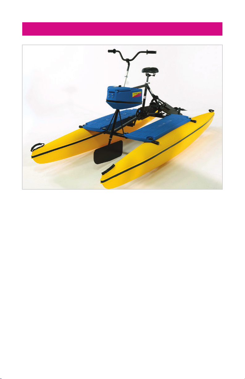
Thank you for purchasing the EXPLORER® HydroBike®! We are sure you
will enjoy your new EXPLORER® for many years to come.
Please take a few minutes to read this manual before using the
EXPLORER®. Although the EXPLORER® is simple to operate, this manual
contains information about craft limitations, safety features and
maintenance obligations you must understand to enjoy the EXPLORER® to
its maximum capabilities. Information about the EXPLORER® is included in
this manual that you might not discover on your own.
If you have any questions regarding your EXPLORER® refer to our website
at www.HydroBikes.com.
www.HydroBikes.com | 3
Page 4

SAFETY INFORMATION
• Read this manual completely before assembling and operating
®
your EXPLORER
.
• Consult a competent medical authority prior to undertaking any exercise
or fitness program that involves the use of the EXPLORER®.
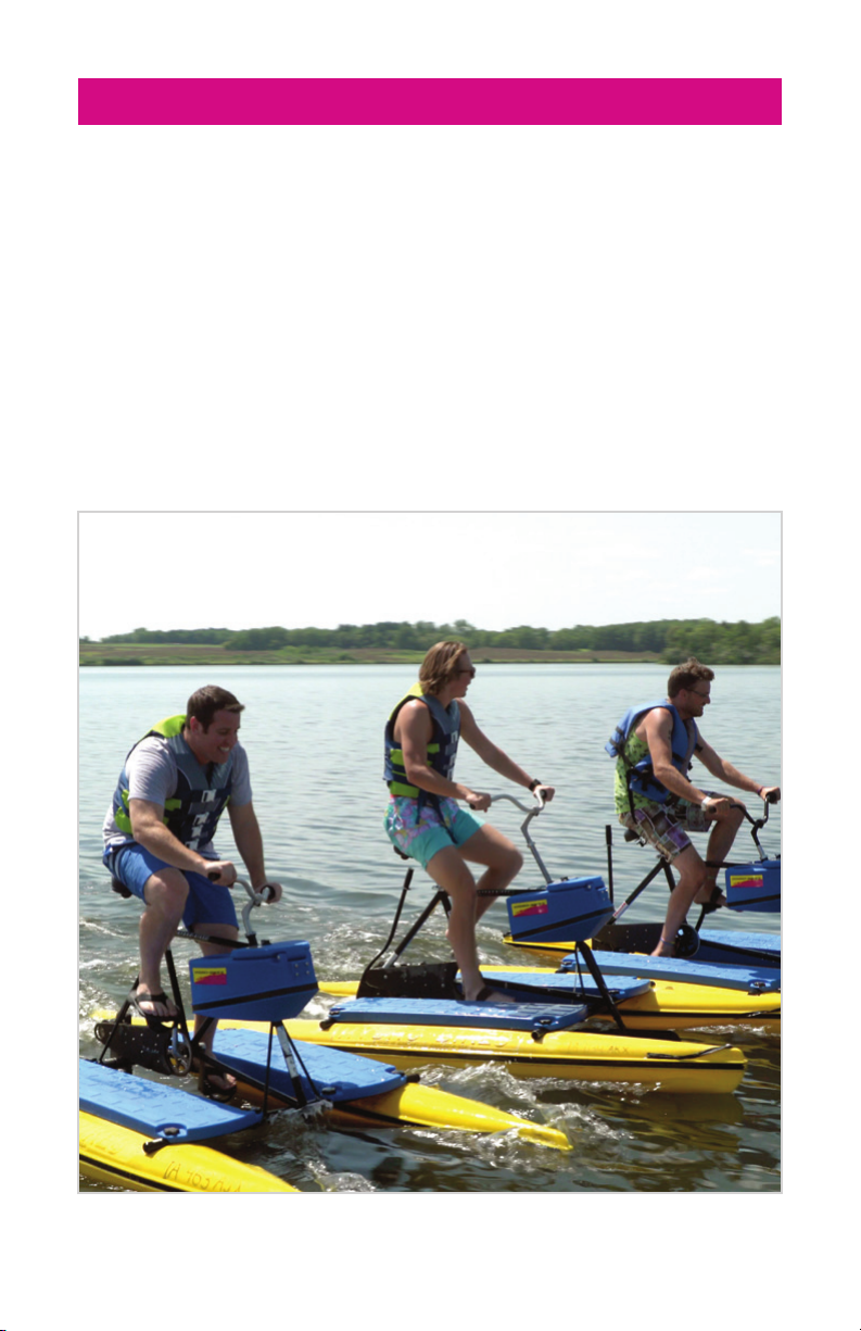
• ALWAYS wear a U.S. Coast Guard approved personal flotation device
(PFD) when riding on the EXPLORER®.
• The maximum load capacity of the EXPLORER® I is 400 pounds; 600
pounds for the EXPLORER® II.
• Do not carry passengers on your EXPLORER®.
• Do not allow anyone to sit on the handlebars.
• Do not pedal the EXPLORER® from a standing position.
• Avoid swimmers, swimming areas, and boat traffic.
• Know and follow the boating laws and regulations of the area in which
you are using the EXPLORER®.
• Do not operate your EXPLORER® after sunset or before dawn, unless
your EXPLORER® is equipped with lights. Please follow the laws
regarding boating in the dark in the area in which you are using
the EXPLORER®.
• Watch for underwater obstacles when operating the EXPLORER® in
shallow water.
• Ask about local conditions before using your EXPLORER® in
unfamiliar waters.
4 | www.HydroBikes.com
Page 5
SAFETY INFORMATION
®
• Never use your EXPLORER
in stormy weather or when there is lightning.
Seek shelter on shore if a storm is coming.
• Although the pedals are suitable for bare feet, wearing hard-bottomed
footwear (sneakers or other water footwear) is recommended.
• Never wear loose clothing that could become entangled in any moving
part of the EXPLORER®.
• Never use the EXPLORER® while under the influence of alcohol or drugs.
www.HydroBikes.com | 5
Page 6
ASSEMBLE YOUR HYDROBIKE
®
How to begin
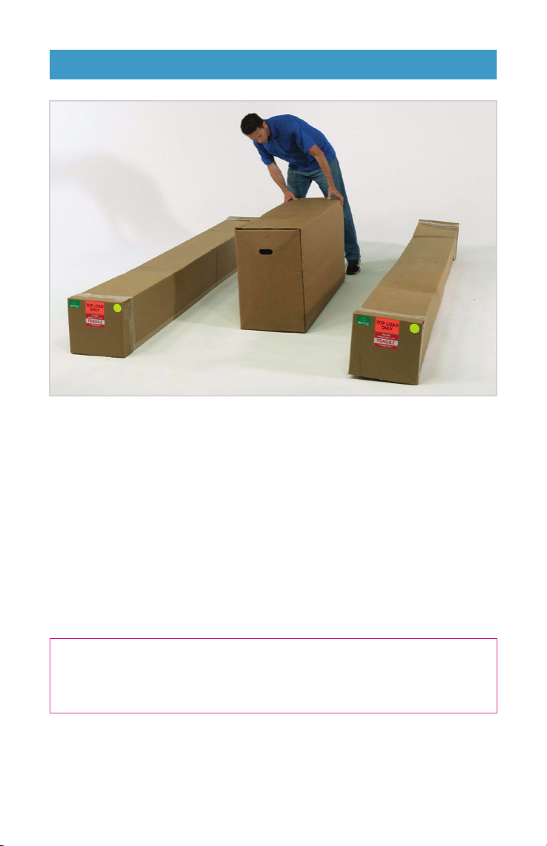
Your HydroBike® will be delivered in three large boxes, two for the floats
and one for the bike, frame and additional parts. During transport, the
float boxes may be askew. This is normal from transporting and not an
error from the delivery service, and does not damage the float.
Choose a flat, hard surface to unpack and assemble your HydroBike®.
Something like a garage floor or even your driveway. Assembling on a
dock or the grass could end up with some lost parts. Once everything is
accounted for, it’s time to get started.
Rather watch a video on assembling your HydroBike®?
Visit www.HydroBikes.com/assembly.
6 | www.HydroBikes.com
Page 7
ASSEMBLE YOUR HYDROBIKE
Bike Frame
Assembly
Cross
Support Bar
Prop
Sideboard Sideboard
Float
Handlebar
Console
Cross
Support Bar
Lever
Seat
Seat Post
®
Float
Handlebar Grip
Handlebars
Rudder and Shaft
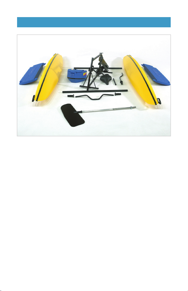
The EXPLORER® I Parts Schematic
Here is everything that comes in the three boxes.
•
Floats (2)
•
Sideboards (2)
•
A rudder and shaft
•
A handlebar console
•
A bike frame assembly
•
Cross support bars (2)
•
Handlebars
•
Handlebar grips (2)
•
A prop lever
•
A seat
•
A seat post
•
Handlebar stem (not pictured)
•
A plastic bag of hardware
needed for assembly (not
pictured)
Handlebar Grip
www.HydroBikes.com | 7
Page 8

ASSEMBLE YOUR HYDROBIKE
®
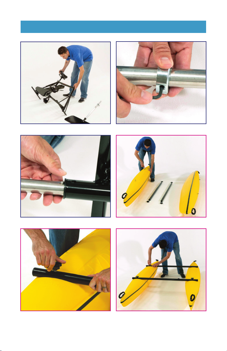
STEP 1:
Attach the rudder
Lay the bike frame on its side (A).
Locate the Rudder Assembly. Remove the collar on rudder pipe by
loosening the bolt with the provided allen wrench (B).
Then, insert the rudder assembly into the front tube of the bike frame by
depressing the two spring-loaded buttons and sliding the rudder shaft up
until the two spring loaded buttons extends beyond the top of the bike tube
(C). Next, fit the rudder collar over the top of the rudder shaft and tighten
until snug (B). Do not tighten completely as it may need adjustment.
STEP 2:
Connect the floats with the cross tubes
Each float has two pre-installed bolts. Locate the black square plug on the
floats (A). This signifies the back of each float. Layout the two cross tubes
and four black knobs between the floats for easy access during this step.
Stabilize the float by standing over it and securing it upright with your legs. Fit
the first cross tube onto the front bolt on one of the float. Secure it to the bolt
by threading a black knob (B). Do not tighten fully. Holding the cross tube,
step over the second float and secure with your legs again for the bolt to be
upright. Insert the cross tubes on to the second float. Use a second black knob
to secure the cross tube. Do not tighten fully. Repeat this step with the second
cross bar at the float rear bolts (C).
8 | www.HydroBikes.com
Page 9
ASSEMBLE YOUR HYDROBIKE
STEP 1: A STEP1: B
®
STEP 1: C STEP 2: A
STEP 2: B STEP 2: C
www.HydroBikes.com | 9
Page 10

ASSEMBLE YOUR HYDROBIKE
®
STEP 3:
Attach the bike frame
The bike frame sits on top of the cross tubes. Set the base of the bike
frame on the cross tube with the Rudder at the front (A). Align all four
holes on the base of the bike frame with the holes on the cross tubes (B).
The bike will be secured to the crossbar in a few more steps.
In the parts bag, locate the six bolts and washers. Insert the washers into
the bolts to be flush with the bolt head (C). Repeat for all 6 bolts. We will
use 4 of these bolts now and the remaining two in a later step.
STEP 4:
Install sideboards
Remove the two black knobs on one side of the HydroBike and place them
aside but within reach (A).
Notice the thicker edge of the sideboards is placed on the inside of the
Hydrobike (B). Place the sideboard on the two bolts on the float. Check that
the holes on the inside of the sideboard are aligned with the bike frame and
cross tube holes. Secure the outside of the sideboard by replacing the black
knobs over the bolts fixed on the floats, then insert a bolt from the bottom up,
securing with black clamping knobs on top (C). Do not tighten knobs fully.
Repeat with another bolt and knob for the rear of the sideboard.
Repeat these steps for the other sideboard.
Once all bolts are affixed with black knobs, tighten all knobs by hand with
moderate force.
10 | www.HydroBikes.com
Page 11

ASSEMBLE YOUR HYDROBIKE
STEP 3: A STEP 3: B
®
STEP 3: C STEP 4: A
STEP 4: B STEP 4: C
www.HydroBikes.com | 11
Page 12

ASSEMBLE YOUR HYDROBIKE
®
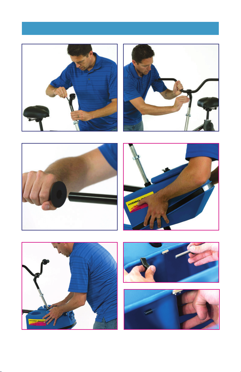
STEP 5:
Install handlebars
First, remove the rubber sleeve from the bottom of the handlebar stem. Insert
the bottom of the stem into the rudder shaft about 6” inches. Angle the stem
to the front of the bike and tighten the bolt on the top of the stem with the sixmillimeter hex wrench provided (A).
Slide the handlebars into position through the eye hole at the top of the stem.
Center the handlebar and angle at your preferred position tighten the bolt
on the stem that is placed under the eye hole with the six- millimeter hex
wrench (B). You can adjust the height and angle of the handlebars after fully
assembled.
Place the hand grips over the handlebar ends by pushing firmly and slowly
twisting until all the way on (C).
STEP 6:
Attach the center console
Facing the front of the bike assembly, slide the slot in the center of the
console over the Rudder tube on the front of the Hydrobike® (A). The top of
the console should be flush with the bike’s crossbar (B).
To secure the console to the bike frame, you will use two bolts and two
wing nuts (C). Open the hatch and find holes in the center slot of the
console for each bolt. Press the bolt with a rubber washer through the
center slot and secure with a wing nut.
12 | www.HydroBikes.com
Page 13
ASSEMBLE YOUR HYDROBIKE
STEP 5: A STEP 5: B
®
STEP 5: C STEP 6: A
STEP 6: B STEP 6: C
www.HydroBikes.com | 13
Page 14

ASSEMBLE YOUR HYDROBIKE
®
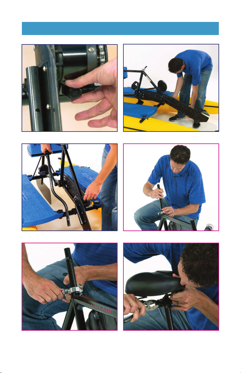
STEP 7:
Install the prop assembly
Next up is installing the prop assembly into position. With one hand
securing the prop assembly, reach down and loosen the black locking bolt
near the rear hub (A) before lowering the prop arm to an approximate
forty-five-degree angle (B). Re-secure the locking bolt with light force. Over
tightening this bolt could damage the locking bolt.
Locate the lever arm bracket on the side of the drivetrain (C). To insert the
lever into the bracket, depress the two silver buttons and slide in slowly
until the buttons lock into the bracket. Test the lever’s effectiveness by
raising and lowering the drive unit.
For transport, press the prop lever down in a forward position, securing it
in the left pedal strap.
STEP 8:
Install the seat
Insert the wide end of the seat post into the bike frame and adjust to a
suitable height (A).
To tighten the seat post clamp, hold the bolt head with your hand or a
pair of pliers while turning the lever side in a clockwise direction for two
to three revolutions (B). With your thumb, fold the lever downward. If the
lever moves with too little pressure or resistance, tighten slightly until the
lever securely holds the seat post. Make sure the lever is pointed down
when tightened and flush with the bike frame.
Next, fit the seat onto the end of the seat post and adjust to a level
position. Secure the nut with an adjustable wrench or pliers (C).
14 | www.HydroBikes.com
Page 15
ASSEMBLE YOUR HYDROBIKE
STEP 7: A STEP 7: B
®
STEP 7: C STEP 8: A
STEP 8: B STEP 8: C
www.HydroBikes.com | 15
Page 16
TRANSPORT YOUR HYDROBIKE
®
The EXPLORER® can easily be transported.
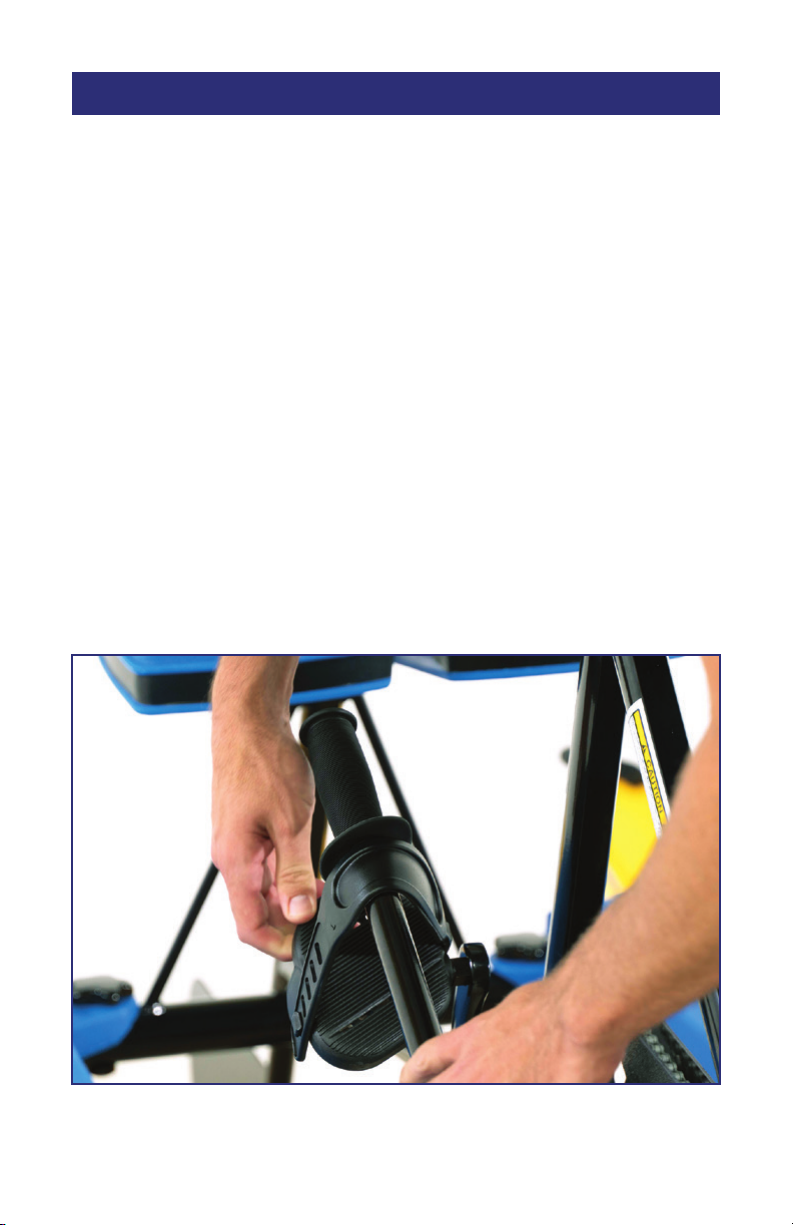
NOTE: The propeller drive train should be fastened in the UP position for
transporting (A).
In general, there are three easy ways to transport your EXPLORER®.
1. Trailer or Truck.
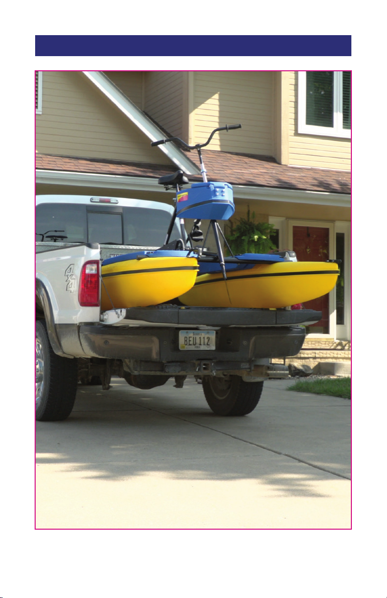
Set one fully assembled EXPLORER® on a trailer or in a truck and fasten
securely (B).
2. On Top of a Car.
Set one fully assembled EXPLORER® onto a car-roof rack, and fasten
securely. Make sure that the car-roof rack is rated for the proper weight of
the EXPLORER® and other miscellaneous gear.
3. Disassembled.
Disassemble the EXPLORER® and transport the individual sections.
Two EXPLORERS® can be transported in the same space required for one.
A
16 | www.HydroBikes.com
Page 17
TRANSPORT YOUR HYDROBIKE
®
B – FASTEN DOWN THE FRAME OF THE HYDROBIKE TO THE FRAME OF YOUR VEHICLE WITH
APPROPRIATE TIE DOWNS.
www.HydroBikes.com | 17
Page 18
PREPARE YOUR HYDROBIKE® FOR THE WATER
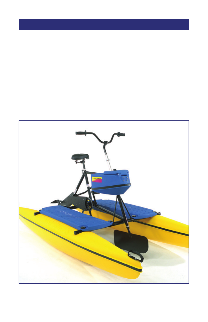
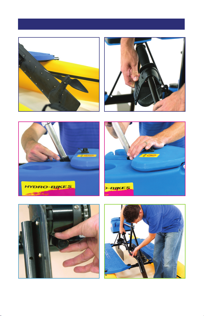
Both the rudder in the front and propeller drivetrain in the back, are in
travel position (A). Once in the water and ready to use, adjust the front
rudder by depressing the spring knobs on the rudder shaft and slide it
®
down (B). When removing the HydroBike
from the water or beaching
the HydroBike®, slide the rudder up until the spring knobs release. The
propeller drivetrain will also need to be lowered for use once you are
in the water. Loosen the black lock bolt in the rear of the bike (C) and
allow the drive train to fold all the way down to be vertical (D). You may
adjust the drive train for shallow waters and if you would like to beach the
HydroBike®.
A
18 | www.HydroBikes.com
Page 19
PREPARE YOUR HYDROBIKE® FOR THE WATER
A A
B B
C D
www.HydroBikes.com | 19
19
Page 20

OPERATE YOUR HYDROBIKE
®
This section explains various things you should know about your EXPLORER®
before attempting to ride.
Precautions
• Do not stand or sit on the front or back tips of the floats while the
EXPLORER
• When the EXPLORER
®
is in the water.
®
is on land, be sure the propeller drive train is
in the UP position.
• The EXPLORER® requires a depth of at least 18” of water. If the
propeller drive train is in the DOWN position before you step onto
the EXPLORER®, make sure the water is deep enough so that the drive
train does not touch the bottom. This may damage the propeller.
Getting Started
Once you have arrived at the water and have unloaded your EXPLORER
®
into the water:
Step 1
Adjust the seat to desired height.
Step 2
Loose Drive Train bolt (should be free to move up or down with your Drive
Train lever minimal amount of resistance)
Step 3
Lower the handlebars/rudder to the DOWN position, for the best steering
results. (See the “Adjusting the Rudder” section.)
Step 4
Begin pedaling to move forward or move in reverse by pedaling backwards.
20 | www.HydroBikes.com
Page 21

OPERATE YOUR HYDROBIKE
Adjusting the Rudder
Your EXPLORER® has two rudder positions.
®
UP Position
Use the UP position when the EXPLORER
®
is in shallow water or out of
the water. In this position, the bottom of the rudder is above the bottom of
the floats.
DOWN Position
Use the DOWN position for the best steering results. In this position, the
bottom of the rudder is lower than the bottom of the floats. To put the rudder
in the DOWN position, depress the two buttons on the rudder assembly
tube and slide the handlebars down.
Steering
Turn the handlebars to steer, just as you would on a bicycle. Turn gradually.
Over-steering can cause the EXPLORER® to slow down. Keep at 10 & 2.
Stopping
There are three ways to stop your EXPLORER®:
• Stop pedaling.
• Pedal backwards.
• Turn the handlebars sharply to either the right or left, so that the rudder
is perpendicular to the floats.
www.HydroBikes.com | 21
Page 22

EXPLORER® I AND EXPLORER® II SPECIFICATIONS
EXPLORER® I
Width (Hull-Hull): ............... 42 in.
Width (Outside): ................ 55 in.
Weight: .......................... 95 lbs.
DIAGRAM/DRAWING OF EXPLORER I & 2
Capacity: ...................... 400 lbs.
EXPLORER® II
Width (Hull-Hull): ...............84 in.
Width (Outside): ................ 97 in.
1
Weight: ........................170 lbs.
2
Capacity: ..................... 600 lbs.
Common Features/Specifications
Length: .......................................................................................10 ft.
Height: .....................................................................................53 in.
Gear Ratio: ............................................................................... 8.6.1
Propeller Diameter:.....................................................................12 in.
Prop Draft – 200 lb. rider: ..........................................................18 in.
Hulls: ............................................................ Roto-Molded Polyethylene
Hull Draft – 200 lb rider: ..............................................................9 in.
Frame – 19 inches: ........................................Powder-Coated Aluminum
Adjustments: ................................................. Quick Release Seat Clamp
1
Weight may vary with accessories
2
Includes rider and cargo
1
2
MAINTENANCE INFORMATION
For maintenance information please refer to our Maintenance Manual
or visit www.HydroBikes.com.
22 | www.HydroBikes.com
Page 23
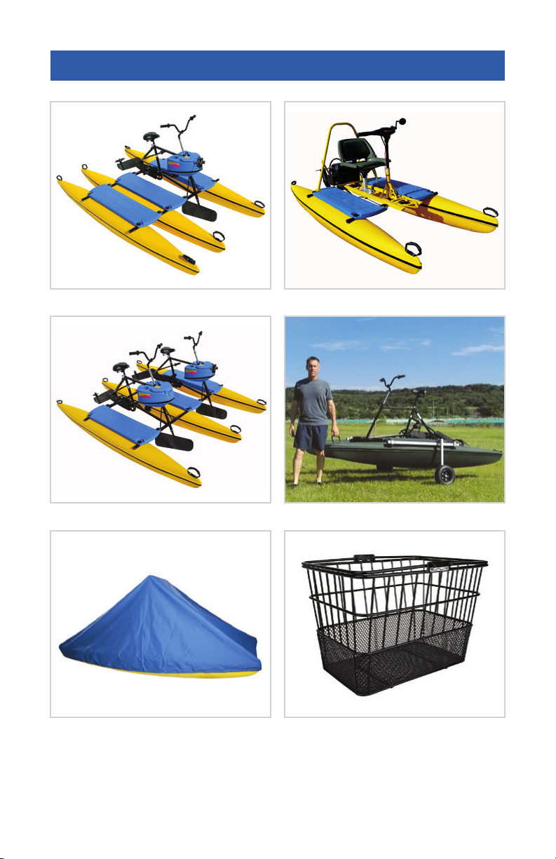
ADDITIONAL PARTS/ACCESSORIES
THE ANGLER MODEL THE CRUISER MODEL
®
EXPLORER
COVER BASKET
II MODEL THE HYDRO PAL WHEEL KIT
For additional parts, chain oil and other accessories, please visit
www.HydroBikes.com.
www.HydroBikes.com | 23
Page 24

Now your ready to enjoy your HydroBike® and experience
your waterfront in a whole new way. Send us pictures of you
enjoying your HydroBike® to our Facebook page @HydroBikes.
Thanks again for your purchase and enjoy your HydroBike®.
888-403-9012 | www.HydroBikes.com
@HydroBikes
 Loading...