

Page 1
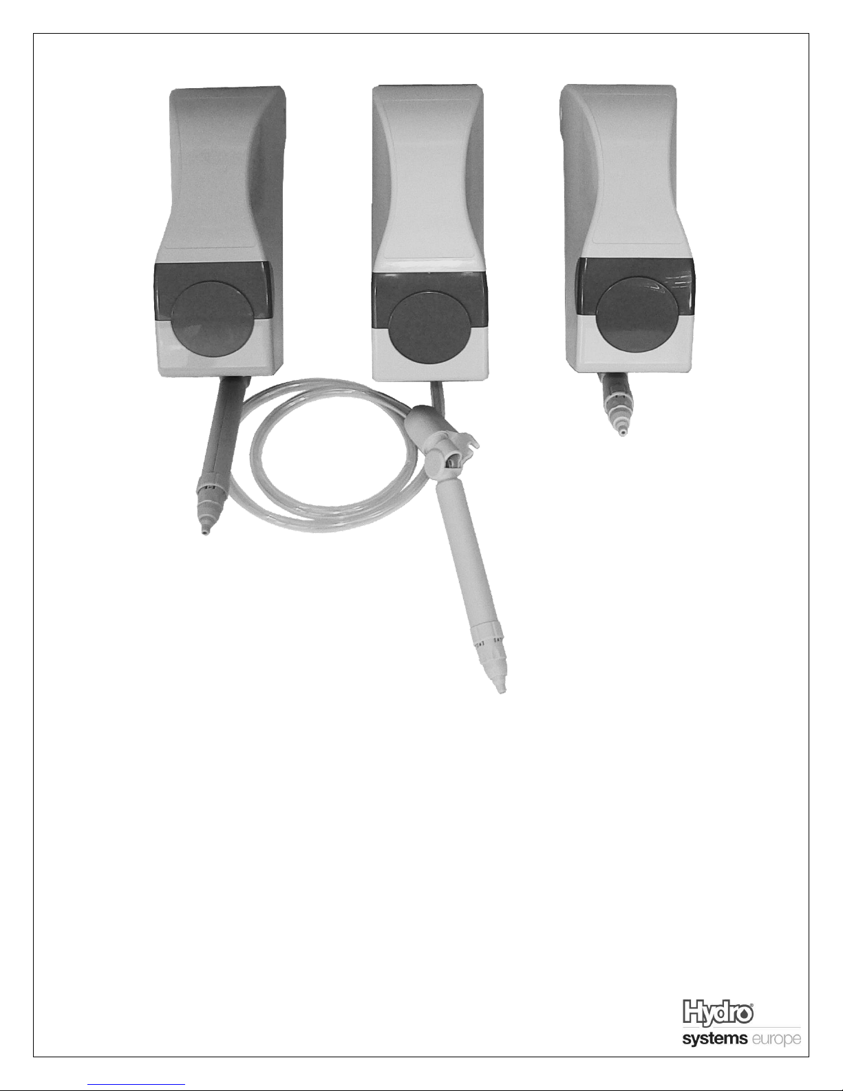
Instruction, Installation & Operation Manual
MultiDose
Sink / Bucket / Bottle
10091099 – Rev1.1 – 25.02.2013 - Page 1
Page 2
A) Description
The MultiDose is a unique hand pump designed to deliver accurate doses of concentrated chemicals into sinks, bottles,
buckets, and other containers.
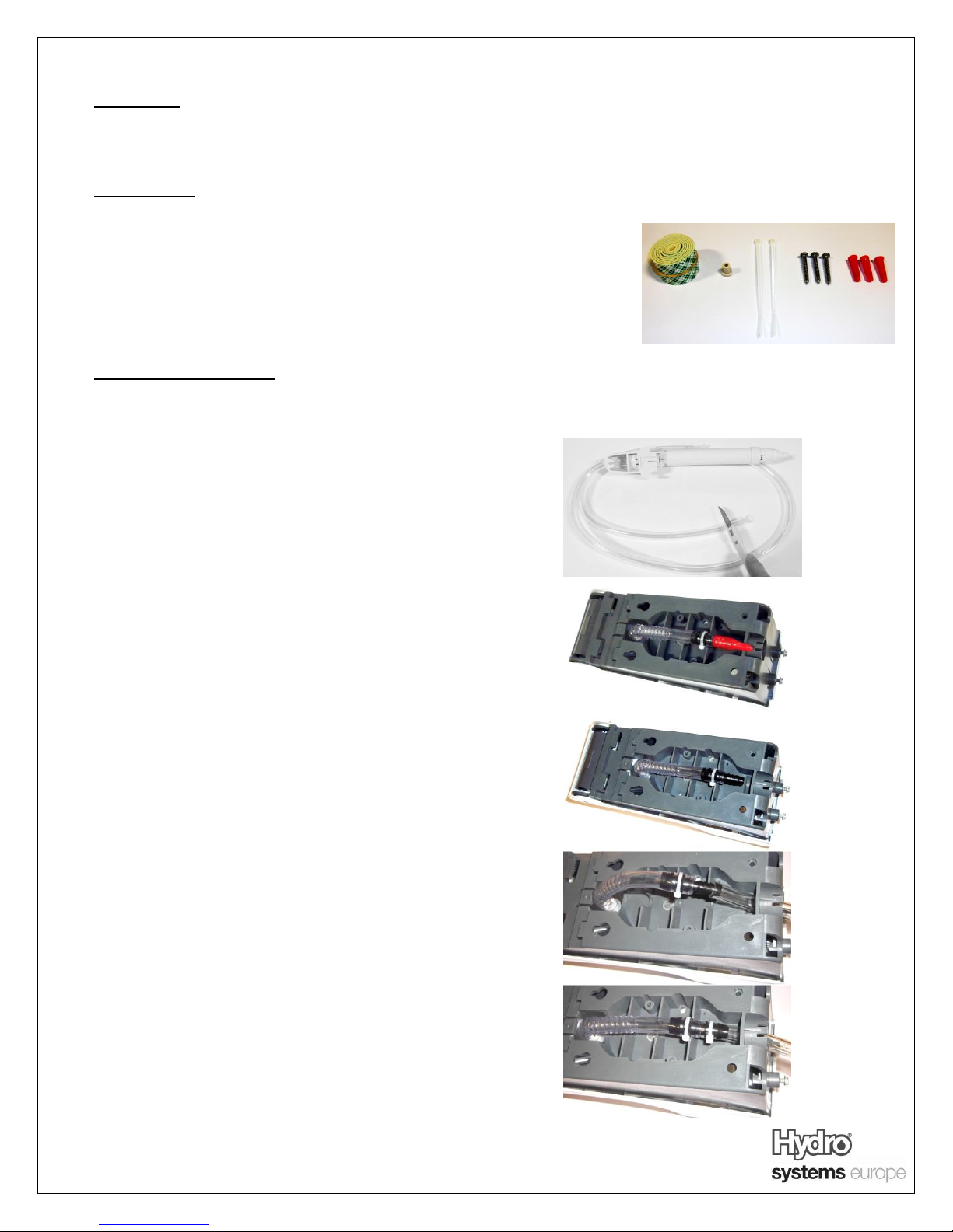
B) Box Contents
MultiDose unit
Instruction sheet
Discharge spout assembly
(Bucket Unit only)
Installation kit
o Wall Screws
o Wall Anchors
o Double Sided Tape
o Double Hose Barb
Adaptor
o Cable Ties
C) Installation & Operation:
Each unit is tested to ensure quality and will contain water. This water is used to prime the pump the first time it is used.
Site Survey and Installation Requirements
Before an installation takes place it is advisable to
complete a site survey to ensure the MultiDose can be
installed in a position that meets all of the requirements
listed below.
i. Ensure the wall/substrate is of a quality to safely
mount the dispenser
ii. The floor around the unit must be non-slip or have
non-slip matting to avoid slippages
iii. The unit must be installed in a well-lit area, or an
area that can be lit
iv. Carry out a Risk Assessment for the area in which
the unit is mounted
Connection of Discharge Tube (Bucket units only)
1) Select desired position of dispenser unit on wall
Recommended height is 146cm (1460mm) to top
screw holes
2) Cut discharge spout tubing to appropriate length for
selected application.
3) At rear of dispenser, remove red cap from hose barb
fitting. Take care to keep the maximum amount of
water inside the unit as possible to aid priming
4) Feed previously cut discharge tubing through exit
hole on underside of dispenser and attach to hose
barb fitting
5) Secure tubing with cable tie provided.
10091099 – Rev1.1 – 25.02.2013 - Page 2
Page 3

II. Dosage Settings:
1. This dispenser is capable of dispensing between 5 and
30 mls in 5 ml increments. To set dosage, adjust the
dosage stop plate to the desired dosage and tighten
two screws below as shown on the right.
2. Dosage may be verified by visible screw thread next to
appropriate dosage on dosage stop plate. Image on
right shown at 5mm setting.
III. Mounting Instructions:
1. To mount the dispenser on wall, either use
Template on page 4, and screw in desired
location using 3 screws and wall anchors
Double sided tape.
2. For Bucket fill model mount discharge spout
assembly in desired position on wall below the
dispenser using 2 screws and wall anchors.
Recommended height is 43cm (430mm) to spout
screw holes
IV. Connection of chemical feed tube
1. Fit double hose barb adaptor (supplied) into end of
chemical inlet tube protruding from bottom of
dispenser. Secure with cable tie
2. Connect chemical feed tube onto other end of
adaptor. Secure with cable tie.
3. Immerse end of chemical feed tube into chemical
container.
Note:
Never mount chemical above dispenser
V. Priming Unit:
1. Raise cover completely until it snaps into fixed
position, exposing pump.
2. Push plunger rapidly and continuously several times
until all air is purged from line. It will be necessary
to push plunger multiple times to prime unit.
3. Dispenser is now ready to operate.
10091099 – Rev1.1 – 25.02.2013 - Page 3
Page 4
Problem
Solution
Unit does not prime
Check pickup tube is fully immersed in
chemical
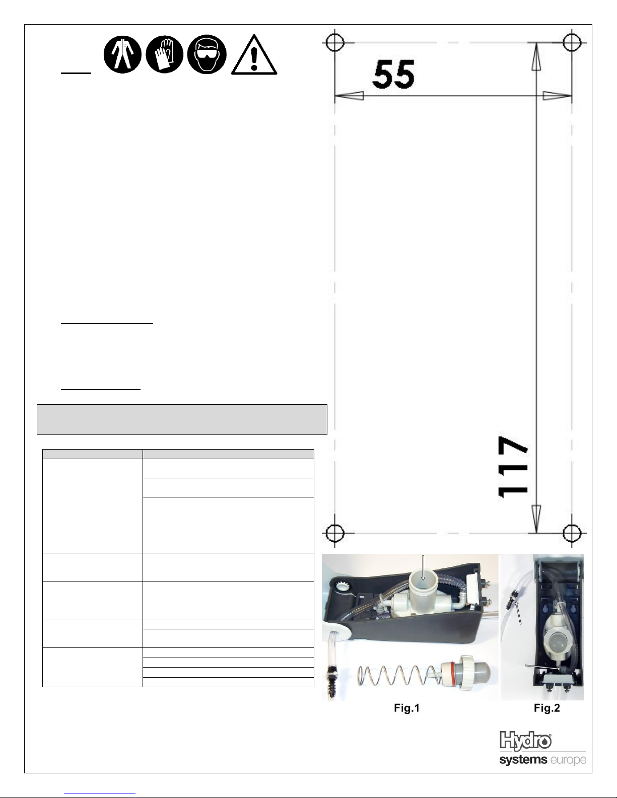
Check clamps shown in Fig.2, if loose,
replace with new cable tie
Remove unit from wall, Carefully unscrew
collar and remove plunger and spring from
chamber, Fill chamber with clean water to
just below lip (Fig.1), Re-insert spring and
plunger, then screw collar back on tight
Unit does not hold
prime
Check clamps shown in Fig.2, if loose,
replace with new cable tie
Unit is giving a short
dose (less than
expected)
Check all above Solutions to ensure
chamber is fully primed
Plunger is slow to
return
Check pickup tube for kinks
Check strainer in end of pickup tube for
blockages
Nozzle Leaking
Ensure nozzle is seated securely
Check chemical is not mounted above unit
Clean nozzle thoroughly
Replace nozzle
D) Safety
Please use this equipment carefully and observe all warnings and
cautions.
Wear PPE when dispensing chemicals or other materials or when
working in the vicinity of all chemicals, filling or emptying equipment.
Always observe safety and handling instructions of the chemical
manufacturers.
Always direct discharge away from you or other persons or into
approved containers.
Always dispense cleaners and chemicals in accordance with
manufacturer's instructions.
Always exercise caution when maintaining your equipment.
Always re-assemble equipment according to instruction procedures.
Be sure all components are firmly screwed or latched into position.
Keep equipment clean to maintain proper operation.
You must follow all precautions as advised on the product safety data
sheet
E) Mounting Template
The mounting template is displayed in the background of this page.
The mounting holes are 5.5cm (55mm) wide, and 11.7cm (117mm)
high
F) Troubleshooting
When doing maintenance on equipment please ensure you are following
all guidelines in the Safety section
Unit 3, The Sterling Centre, Eastern Road, Bracknell, Berkshire, RG12 2PW, UK
Tel: +44 (0)1344 48 88 80 Fax: +44 (0)1344 48 88 79 www.hydrosystemseurope.com
10091099 – Rev1.1 – 25.02.2013 - Page 4
 Loading...