

Page 1
ICS 8950
Integrated Cleaning System
Rechargeable Battery
Page 2
THANK YOU FOR CHOOSING OUR PRODUCTS
Hydro Systems manufactures quality chemical proportioners. Please use this equipment carefully and observe all warnings and cautions.
WEAR
ALWAYS
CLEAN
protective clothing and eyewear when working in the vicinity of chemicals or other
materials, when fi lling or emptying equipment or changing metering tips.
re-assemble equipment according to instruction procedures. Be sure all components are fi rmly screwed or latched into position.
direct discharge away from you or other persons or into approved containers.
exercise CAUTION. Dispense cleaners and chemicals in accordance with manu-
facturer’s instructions.
observe safety and handling instructions of the chemical manufacturers.
equipment after each use to maintain proper operation.
Packing List
Unit with integral 12.5 gallon water reservoir
Battery & charger (installed)
Spray attachment w/ 2 nozzles (installed)
15 ft. discharge hose (installed)
(2) Bottle holders
Metering tip kit
Instruction manual
(2) Chemical feed line assemblies (installed) 1 split for 2 dilutions of same chemical, include:
Tube
Weight
Strainer
Cap
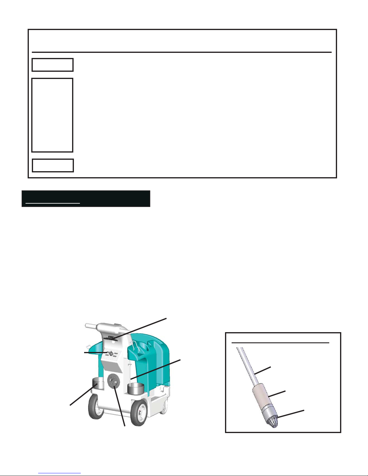
Battery charger
cord wrap
Control panel
Chemical bottle
holder for 1 gal.
round.
Water fi ll port
(access to water pick-up assembly,
see Fig. A)
Fig. A Water pick-up assembly
Chemical feedline assembly
1/4” PVC tube
Ceramic weight
Foot valve
2
Page 3
Overview:
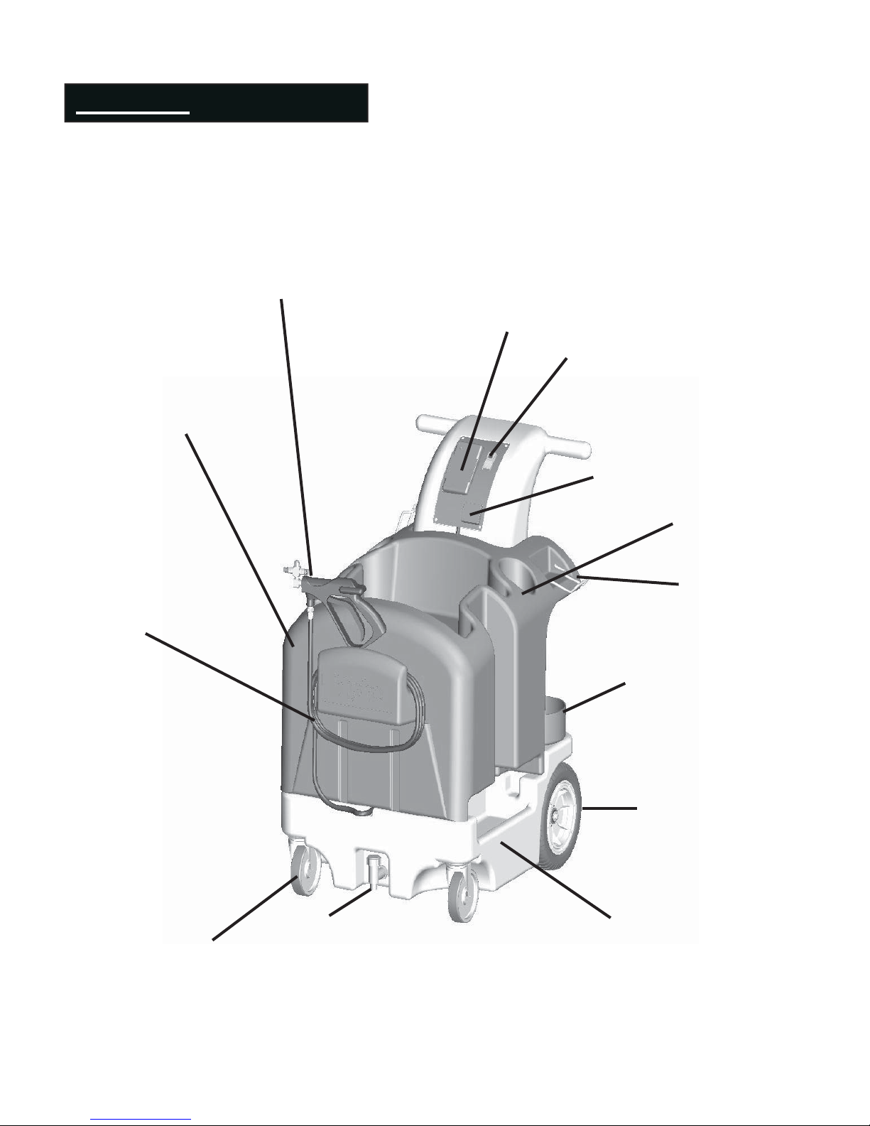
The ICS 8950 is a battery powered, portable, self-contained unit designed to make daily
maintenance of your facility easier. This unit includes the following features:
Spray attachment with two nozzles
(solution and rinse)
Battery Charger
On/Off Switch
Top
Battery Life
Indicator
Storage for spray bottle
15 ft. discharge hose
Locking casters
Sign hanger
Chemical bottle holder
Easy roll wheels
Tap style drain
Fresh water reservoir
12.5 Gal.
3
Page 4
Initial Set-up
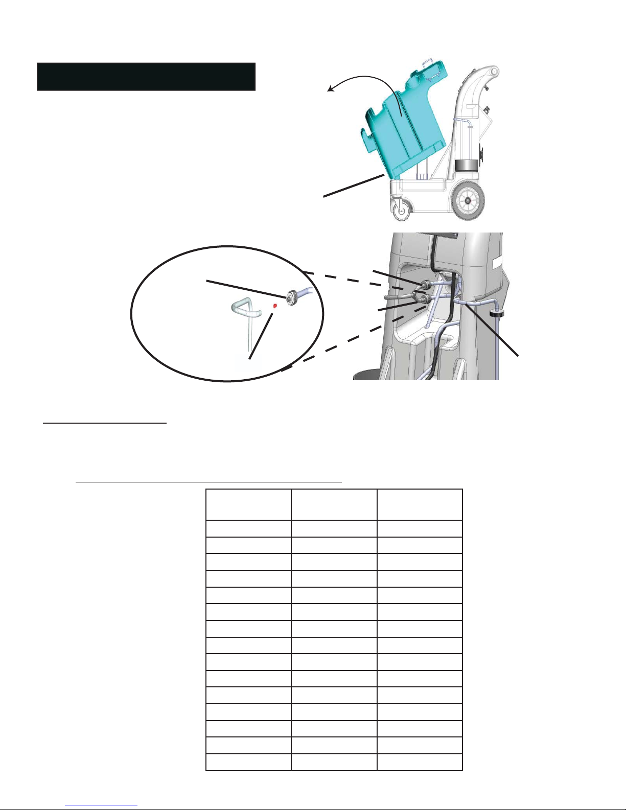
Remove any items sitting on the cart top.
1.
Remove cart top by lifting near the chemical
2.
bottles. See Fig. B.
Remove tubing from checkvalve/metering tip
3.
holder.
Push the selected metering tip into metering
4.
tip holder. Put clean metering tips into any
unused lines. See Fig. C.
Replace tubing.
5.
Connect the red wire to the red
6.
terminal on
the battery.
7.
Replace top.
Check valve/
metering tip
holder
Fig. B
Pegs
Fig. C
Chemical “1”
Chemical “2”
Metering Tip
Chemical “3”
Note: Feed lines are marked corresponding to numbers on control panel.
Metering Tip Selection:
The fi nal concentration of the dispensed solution is related to both the size of the metering tip opening, and
the viscosity of the liquid being siphoned. For water-thin products, the chart can be used as a guideline.
Because dilution can vary with water temperature and pressure, and if the product is noticeably thicker than
water, dilution rates shown should be viewed as approximate.
Orifi ce
Size
0.128
0.098
0.070
0.052
0.043
0.040
0.035
0.028
0.025
0.023
0.020
0.018
0.014
0.010
Tip
Color
no tip
grey
black
beige
red
white
blue
tan
green
orange
brown
yellow
aqua
purple
pink
Average
Dilution Ratio
4:1
4.25:1
4.5:1
4.5:1
5:1
6:1
7:1
8:1
10:1
12:1
16:1
20:1
24:1
32:1
64:1
4
Page 5
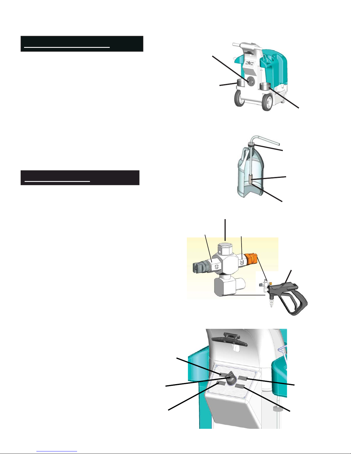
Initial Setup (cont.)
The spray attachment is in the accessory box.
8.
Attach it to the discharge hose.
Remove the black cap from the water fi ll port
9.
(it rotates COUNTER CLOCKWISE to open).
Fill the tank with cool, clear tap water. See
Fig. D.
To connect the chemicals, remove the ship-
10.
ping cap and the seal on your chemical bottle
and discard. Place the strainer and weight
into chemical bottle and screw the chemical
feed line cap on to bottle. See Fig. E.
Fig. D
Water fi ll port
Left
Chemical
Holder
Right
Chemical
Holder
Fig. E
chemical feedline
cap
Prime the Unit
Set the nozzle on the spray attachment to “S”.
1.
See Fig. F.
Set the chemical select valve to any valve posi-
2.
tion. See Fig. G.
Turn the power switch on. The pump should run
3.
for a short time, then stop. (The pump will run
until the discharge pressure reaches the factory set
point. The pump will then turn off until the trigger on the spray attachment is activated.)
Direct the spray nozzle into a drain or other con-
4.
tainer and pull the trigger.
Run until a steady spray pattern is established,
5.
without air in the water stream.
Release the trigger. The pump should stop almost
6.
immediately. If it does not, operate the unit longer as it is not fully primed.
Repeat steps 3 to 6 for all of the valve positions.
7.
1.
Fig. F
Fig. G
Rollover Valve
S
weight
strainer
R
Spray attachment
(Positions 1&2 are diff erent dilutions of
the chemical in the right holder.)
Select Valve
Position 3
Rinse
Position 1
Position 2
5
Page 6

Normal Operation:
The power switch is lighted when it is in the “ON” position.
1.
The pump will run when the trigger on the spray attachment is pulled and stop when it is released.
2.
The rollover valve on the outlet of the spray attachment selects between the two attached spray
3.
nozzles. “S” should be used when applying either product, “R” is used for rinsing. The rinse is a fi ne
spray pattern, while the “S” is a pattern that is more coarse.
Run the unit approximately 10 seconds to fl ush prior chemical from hose.
4.
NOTE: To apply either chemical you must use nozzle “S” for proper dilution.
Out of water/chemical indication:
When the system runs out of either water or chemical, air will enter the water stream and it will become
“rough.” The pump may also continue to run when the trigger is released. Turn off the power immediately, fi ll the water reservoir and/or replace the empty product container, and repeat the priming operation.
CAUTION: Continuous cycling of the pump (continuous, rapid on/off cycles) indicates a problem
with the unit. Have the unit serviced immediately.
CAUTION: Do not operate unit while the charger is plugged into an electrical outlet. If unit does
not operate unless plugged in, check that the battery terminals are connected (see initial set up
proceedure on page 4).
Maintenance:
Daily:
When fi nished using the pump for the day, run the pump two to four minutes with the select valve and
1.
nozzle in rinse position, to purge chemical from the unit. See Fig. G.
Set the nozzle to “S” (keep the select valve in the rinse position) and run for ten seconds.
2.
Turn the unit off with the switch. Relieve the pressure in the discharge hose by pulling the trigger on the
3.
spray attachment after the switch has been turned off. A small amount of water will discharge.
Check the unit for any damage or leakage.
4.
If the unit is going to be stored where it can freeze, drain the water reservoir and run the pump until there
5.
is no more water in the system. Allow the system to thaw before you start the pump.
Plug the unit into a 120 Volt outlet to recharge the battery. The indicator light on the charger will be red
6.
while the battery is charging, and green when the battery is fully charged. Leave the charger plugged in
during long term storage to maintain the battery at peak capacity. Note: It is not necessary to fully discharge the battery before recharging.
NOTE: Failure to follow this procedure after use will void the warranty on the pump.
6
Page 7
Troubleshooting:
The spray is weak or there is no spray. The pump does not operate at full fl ow if there is
1.
air in the system. Air can enter the system from several sources:
Out of water - fi ll the water reservoir and prime the system.
a.
Out of chemical - replace the chemical container and prime the system.
b.
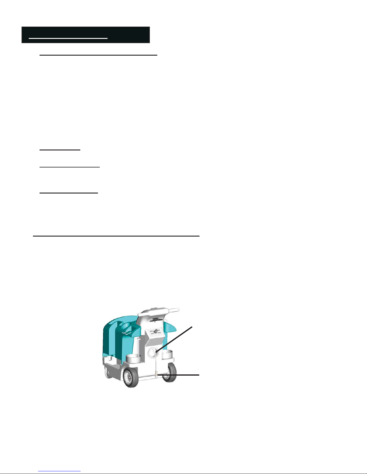
Foot valve is clogged - clean or replace the foot valve in the reservoir. To access the foot
c.
valve, remove fi ll port cap. Pull water pick-up assembly out through fi ll port. The foot
valve is mounted on the end of the water pick-up assembly, and is designed to be removed without tools. See Fig. H.
Leak in one of the fi ttings. Remove the cart top and fi nd the source of bubbles. Correct
d.
the leak.
Battery is low, check battery life indicator, if necessary, recharge.
e.
Pump pulses. There is a pressure switch in the pump. If the pump is pulsing, this switch is
2.
cycling and the life of the pump will be greatly reduced. Have the pump serviced.
Pump not running.
3.
Battery is dead, recharge.
a.
Loose battery connection, check that both terminals are connected.
b.
Pump not priming.
4.
Make sure the water feed line is untangled and lying at the base of the tank. Sometimes
a.
feedlines become tangled in shipping and priming cannot occur.
Note:
- The pump does not contain any fi eld serviceable parts. It should run for 800 to 1000 hours
with no maintenance needed. If leaks occur in the pump, it needs to be replaced.
- The pump is fi tted with a non-adjustable, factory installed, regulator. This regulator is
preset at the factory and should not be adjusted.
Fig. H
Water pick up assembly
(accessed through water fi ll port)
Foot valve
7
Page 8
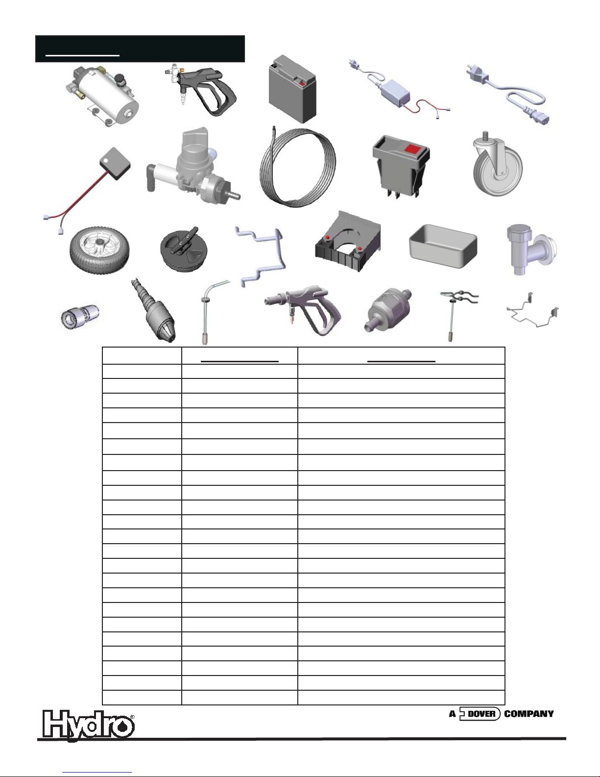
Parts List
1.
6. 10.
11. 12.
17. 18.
7.
2.
19.
13.
3.
8.
14.
4. 5.
9.
15.
21.20.
22. 23.
Part Number Description
1. 10092250 Pump replacement kit
2. 10091845 Spray attachment
3. 10092253 Battery
4. 10092254 Battery charger
5. 10092211 Cord, battery charger
6. 10092255 Battery life indicator
7. 10092262 Chemical selector valve
8. 10091864 Discharge hose replacement, black
9. 10092252 On/off switch replacement kit
10. 10091867 Caster replacement kit (set of 2)
11. 10091866 Wheel replacement kit (set of 2)
12. 10091861 Fill port cap
13. 10092217 Sign hanger
14. 10092258 Mop clips (set of 2)
15. 10092266 Bottle holder - (set of 2)
16. 90084615 Tap style drain
17. 690014 Metering tip kit
18. 10076302 Foot valve, EPDM
19. 10092251 Chemical feed line kit - Single
20. 10092259 Optional foaming attachment
21. 10069255 Check valve
22. 10092645 Chemical feedline split
23. 10092602 Mop bucket retainer kit
16.
10092642 9/08
 Loading...