

Hydro FM-800 Flush Manifold, HYD00-03608-02XT, HYD00-03608-04XT, HYD00-03608-06XT, HYD00-03608-08XT User Manual
...
user manual
FM-8OO Flush Manifold
Safety Precautions
WARNING! Please read these warnings carefully and follow all applicable local codes and regulations.
THANK YOU FOR YOUR INTEREST IN OUR PRODUCTS!
TO AVOID SERIOUS PERSONAL INJURY AND PROPERTY DAMAGE:
WEAR
ALWAYS
NEVER
ATTACH
NOTE
Protective clothing and eyewear when dispensing chemicals or other materials, when working in the vicinity
of chemicals, and when filling or emptying equipment.
Read and follow all safety instructions in safety data sheets (SDS) for all chemicals.
Observe all safety and handling instructions of chemical manufacturer.
Dilute and dispense chemicals in accordance with chemical manufacturer‘s instructions.
Direct discharge away from you and other persons and into approved containers.
Regularly inspect equipment and keep equipment clean and properly maintained.
Use a locally approved back-flow prevention device - not provided - as required for safe, legal operation.
Mix incompatible chemicals that pose hazards.
Only to water tap outlets at 0.2 MPa / 1.7 Bar / 25 PSI Min., 0.6 MPa / 6 Bar / 85 PSI Max. and maximum
water temperature 60°C / 140°F. Operating outside of these parameters will void manufacturer’s warranty
It is recommended to flush with a dedicated COLD water supply only, when possible.
introduction
Package Contents
• FM-800 Flush Manifold Assembly
w/Brackets (P/N varies by model)
• Hardware Kit
• 3/8” Braided Tubing (A 2-foot
section for each port)
Chemical Port
Model Numbers Description
HYD00-03608-02XT FM-800, 2 Product Flush Manifold 3/8” 1/2”
HYD00-03608-04XT FM-800, 4 Product Flush Manifold 3/8” 1/2”
HYD00-03608-06XT FM-800, 6 Product Flush Manifold 3/8” 1/2”
HYD00-03608-08XT FM-800, 8 Product Flush Manifold 3/8” 1/2”
HYD00-03608-01XT FM-800, 2 Product Add-on Kit 3/8” 1/2”
Barb Size
Discharge
Barb Size
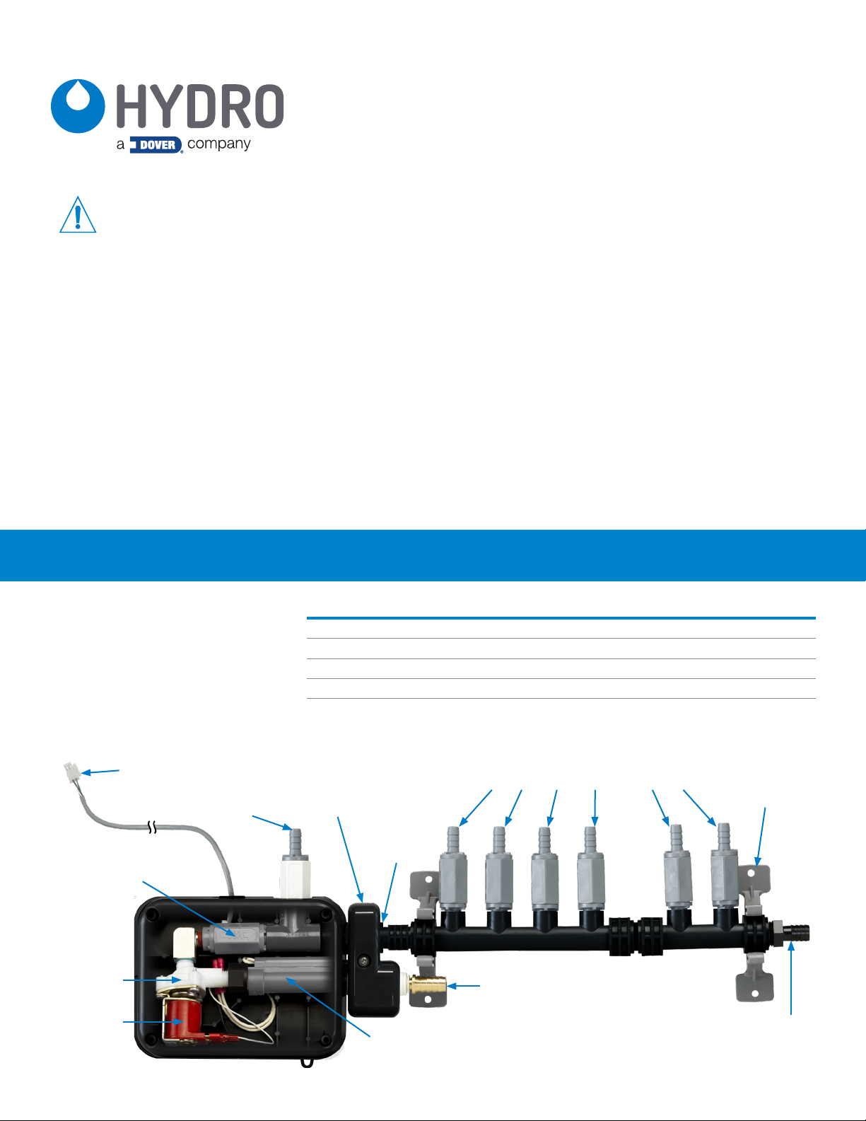
connection to pump stand
inline check valve
water
valve
solenoid
vent
port
inlet
support
manifold
swivel
flow
switch
chemical ports with check valves
water
inlet
wall
hangers
discharge
to laundry

installation
Overview
The FM-800 Flush Manifold is intended for use with our LM-100, LM 200, Electrolux SDS, and LL-6000 liquid laundry
dispensing systems.
This is a single unit that includes a water valve, manifold and integrated flow switch all in one convenient assembly. This FM800 Flush Manifold is designed to provide the easiest and most cost-effective means of flushing liquid laundry products.
The FM-800 Flush Manifold aids in safe delivery of liquid laundry chemical products from the dispensing system to the
washer using water flow (or flush) via a single discharge tube. The dispenser pumps chemical products into the manifold via
integrated check valves that keep unwanted liquids from entering the chemical line and also keep unwanted chemical from
dripping into the water flow. The flush valve controls water flow through the manifold, which in turn transfers product to the
washer. The flush valve may be controlled by our Standard Eclipse, Total Eclipse or Electrolux SDS Controller.
Mounting the Flush Manifold
1. Position the drilling template (located on the packing insert) on the wall near the dispenser pump stand, in the position
and orientation you desire.
2. Using the drilling template and a pencil, mark the location of the required holes (5 total) on the mounting surface.
3. Drill the marked holes with a 1/4” masonry bit and place a wall anchor, supplied, into each hole.
4. Using the swivel, rotate the manifold to the desired angle in 45° increments. Do Not rotate by threaded joints.
5. Secure the manifold assembly to the wall anchors with supplied screws. Note: The long screw (provided) must be
used to secure the electronics cover.
6. Connect the cold water supply line to one of the supplied hose barb fittings (straight or 90°). Once connected, push
the smooth end of the fitting into the press-to-fit connection on the FM-800.
7. Connect hose between the FM-800 discharge and the washing machine.
8. Avoid kinks and other restrictions in discharge tube. Dynamic manifold pressure that exceeds 0.2 MPa / 2 Bar / 30
PSI during operation can severely reduce pump and squeeze tube life. This condition may also cause excessive back
pressure in the squeeze tubes resulting in potential dispensing equipment damage and/or personal safety risks.
IMPORTANT NOTE: Water inlet fitting size is 1/2” hose barb (1/2” ID hose). Flush outlet fitting size is 1/2” hose barb
(1/2” ID hose). To connect other sizes or types of water inlet and/or flush outlet hoses, obtain fittings locally.
Connecting the Pump Tubes
1. Connect one end of the 3/8” ID tubing supplied with the FM-800 to the pump
tube hose barb with hose clamps or tie wraps to ensure a leak-free assembly.
2. Trim the 3/8” ID tubes to fit, but do not connect to the check valves yet.
3. Calibrate each pump using the calibration steps of the system controller,
capturing product at the open ends of the braided tubing.
4. Now connect 3/8” ID tubing to the hose barbs on the check valves. Secure
with hose clamps or tie wraps to ensure a leak-free assembly.
5. Do Not Connect Any Chemical Line To The White Vent Check Valve!
NOTE: Appliances connected to the water mains by detachable hose should use
hoses provided with the appliance and should not reuse previous hoses.
Installing Hard Copper Plumbing
Always use an approved back-flow prevention device and water pressure
regulator. Hose barb fittings can be removed and replaced with the appropriate
fittings to accommodate copper tubing. Use RTV sealant on the plastic plumbing
threads and DO NOT solder to fittings that are threaded into plastic.
A locally approved back-flow
prevention device - not provided may be required for safe and legal
operation. A list of approved backflow prevention devices is listed
below:
- Watts 9D
- Watts 008 - Preferred
- Hydro HYD282511
This apparatus MUST be installed
in accordance with the requirements
of the Plumbing Code of Australia
(PCA) AS/NZS 3500.1, including all
backflow prevention requirements
outlined.
WARNING!
WARNING! For units
installed in Australia:
 Loading...