

Hydro GA-180 Operation And Maintenance Manual

GA-180 Gas Detector
Operation and Maintenance Manual
The information contained in this manual was current at the time of printing. The most current versions of all
Hydro Instruments manuals can be found on our website: www.hydroinstruments.com
GA-180 Rev. 12/20/17
1

GA-180
Gas Detector
Operation Manual
Table of Contents
I. Installation
A. Monitor Installation ..................................................................................3
B. Sensor Installation .....................................................................................3
C. Battery Backup Installation .......................................................................4
II. Operation
A. Navigating the Controller..........................................................................9
B. Operating Screens and Settings ................................................................9
C. Confi guring a Sensor Channel ................................................................10
D. Installing and Confi guring Temperature .................................................16
E. Alarms and Outputs ................................................................................16
F. Modbus Communication .........................................................................20
G. Response Checks (Bump Testing) ..........................................................20
H. Data Logger ............................................................................................21
III. Troubleshooting
A. Installation Check ...................................................................................22
B. Symptoms, Likely Causes, and Suggested Responses ............................22
C. Explanation of Responses .......................................................................23
Figures
1a. Sensor Installation (heavy gases) ............................................................3
1b. Sensor Installation (light gases) ..............................................................3
2. Remove Calibration Cap .........................................................................4
3. Wiring Diagram (inside of door) .............................................................5
4. GA-180 Controller Electronics ...............................................................6
5. Pinout Diagrams for MB108 and MB123 ...............................................7
6. Pinout Diagrams for MB122, MB141, and MB101 ................................8
7. Calibration Cap .....................................................................................12
8. Sensor and Calibration Kit ....................................................................12
9. GA-180 Operating Screens ...................................................................13
10. GA-180 Confi guration Screens .............................................................14
11. GA-180 Modbus Confi guration and Node Enable Screens...................15
12. External Alarm Light and Horn .............................................................19
13. Bump Testing (Chlorine Gas Example) ................................................20
Tables
1. Example Controller Confi gurations ........................................................6
2. Standard Ranges For Hydro Instruments Gas Sensors ..........................11
3. Relay Options for Common Relays (33 & 34) ......................................17
4. Relay Options for Sensor Relays (1-32) ...............................................17
2

I. INSTALLATION AND OPERATION
A. Monitor Installation
All monitors are able to accept either 120 VAC or 240 VAC single phase power at 50-60 Hz. When
connecting A/C power it is imperative that the power source is well grounded. Improper grounding
will disrupt proper operation of the unit.
Warning: Ensure source power is disconnected from main power, prior to making the instrument
connection.
Monitors are NEMA 4X rated and should be installed at/near eye level and protected from exposure
to direct sunlight and rain. The monitor should be installed near, but outside of the chemical storage
room it is monitoring (see Figure 1a and 1b). Four
enclosure for mounting the monitor against the wall.
FIGURE 1a FIGURE 1b
5
⁄16" DIA through holes are provided on the
For gases heavier than air, sensor should be
mounted low.
GAS ALARM
CONTROLLER
GAS SENSOR
12" - 24"
For gases lighter than air, sensor should be
mounted high.
12" - 24"
GAS SENSOR
GAS ALARM
CONTROLLER
B. Sensor Installation
Refer to Figures 1a and 1b for more information.
1. Determine a suitable mounting location. For monitoring gases heavier than air, the sensor should
be placed approximately 12-24 inches from the fl oor. For gases lighter than air, the sensor
should be placed 12-24 inches from the ceiling. Do not place sensor in any location where it
could become wet. This will damage the sensor.
2. Attach the enclosure to the wall using two
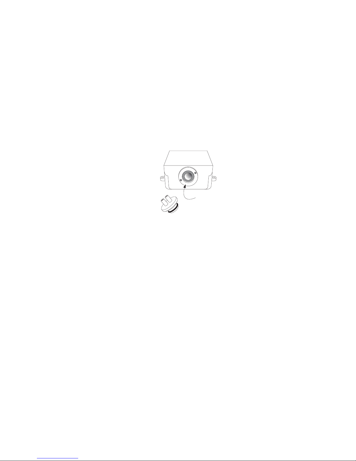
3. Remove sensor calibration cap. Store this cap in a known location as it is necessary for
calibration when using a span gas. See Figure 2.
1
⁄4"-20 mounting screws (recommended).
3
4. If necessary, open the sensor enclosure front cover and reconnect the signal wires. Connect
Red to Red and Black to Black on the terminal strip inside the sensor enclosure. Replace
enclosure front cover and be sure to check that the gasket is evenly sealed around the
enclosure. Also tighten the liquid tight fi tting.
5. If necessary, connect the signal wire to the appropriate terminals. Refer to Table 1 and Figure 4
so that you can connect the sensor to the right channel. The black wire will connect to AI1 or
AI2 and the red wire will connect to V+ depending on the required channel number.
6. Connect GA-180 main power, allow sensor to stabilize.
7. Confi gure the sensor channel. See section II.C.
8. Perform a bump test on all sensors installed on the monitor. Confi rm sensor has appropriate
response to the test gas.
FIGURE 2
Sensor Enclosure
Front
Bottom
Remove calibration cap
at sensor start-up.
Calibration
Cap
C. Battery Backup Installation
1. Disconnect A/C power before beginning this procedure.
2. Insert the battery into the enclosure by removing the surface protection tape and placing the
Velcro strips on the enclosure back plate. The battery should be installed so that the leads are
facing up.
3. Identify the positive (+) and negative (-) leads on the battery. Remove the plastic protectors
on the battery leads and connect the positive lead of the battery to the “BAT +” terminal on the
battery backup board (MB101). Connect the negative lead of the battery to the “BAT –” terminal
on the battery backup board (MB101).
4. Ensure that the appropriate 24 VDC from the power supply is connected to the appropriate PS +
and PS- terminal. For units with battery backup, the DC power must go into these terminals for
proper operation and detection of A/C power failure.
5. If necessary, enable battery backup on relevant sensor channels. Use the screen tree (Figure 11)
to access the relevant screens. Cycle the power to save the enabled battery backup setting.
Note: Battery 1 will need to be enabled to back up sensors 1-4, Battery 2 will need to be enabled
to back up sensors 5-8, Battery 3 will need to be enabled to back up sensors 9-12, and Battery 4
will need to be enabled to backup sensors 13-16. For example, if a system is ordered with 8
sensors then two batteries will need to be installed (into their respective enclosures). Battery 1
and Battery 2 will need to be enabled. If a unit was purchased at the factory to have battery
backup this will have already been done.
4
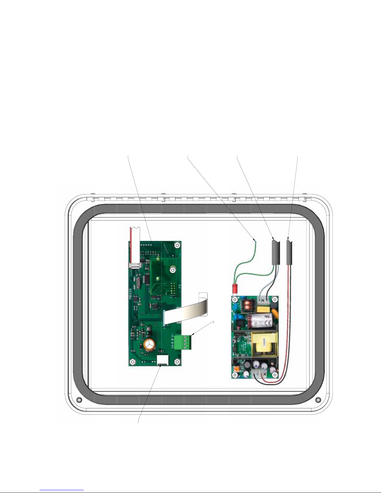
FIGURE 3: Wiring Diagram (inside of door)
0-FLUFXLWERDUG
IRUGDWDORJJLQJ
RSWLRQDO
7R%DFN3ODWH*URXQG/XJ
7R7HUPLQDO%ORFN
*1'JUHHQ
/,1(EODFN
1(87ZKLWH
7R&LUFXLW%RDUG
9EODFN
9UHG
ORJJHU
IRUGDWD
0LFUR6'+&
FDUGVORW
)RU02'%86
&RPPXQLFDWLRQ
5
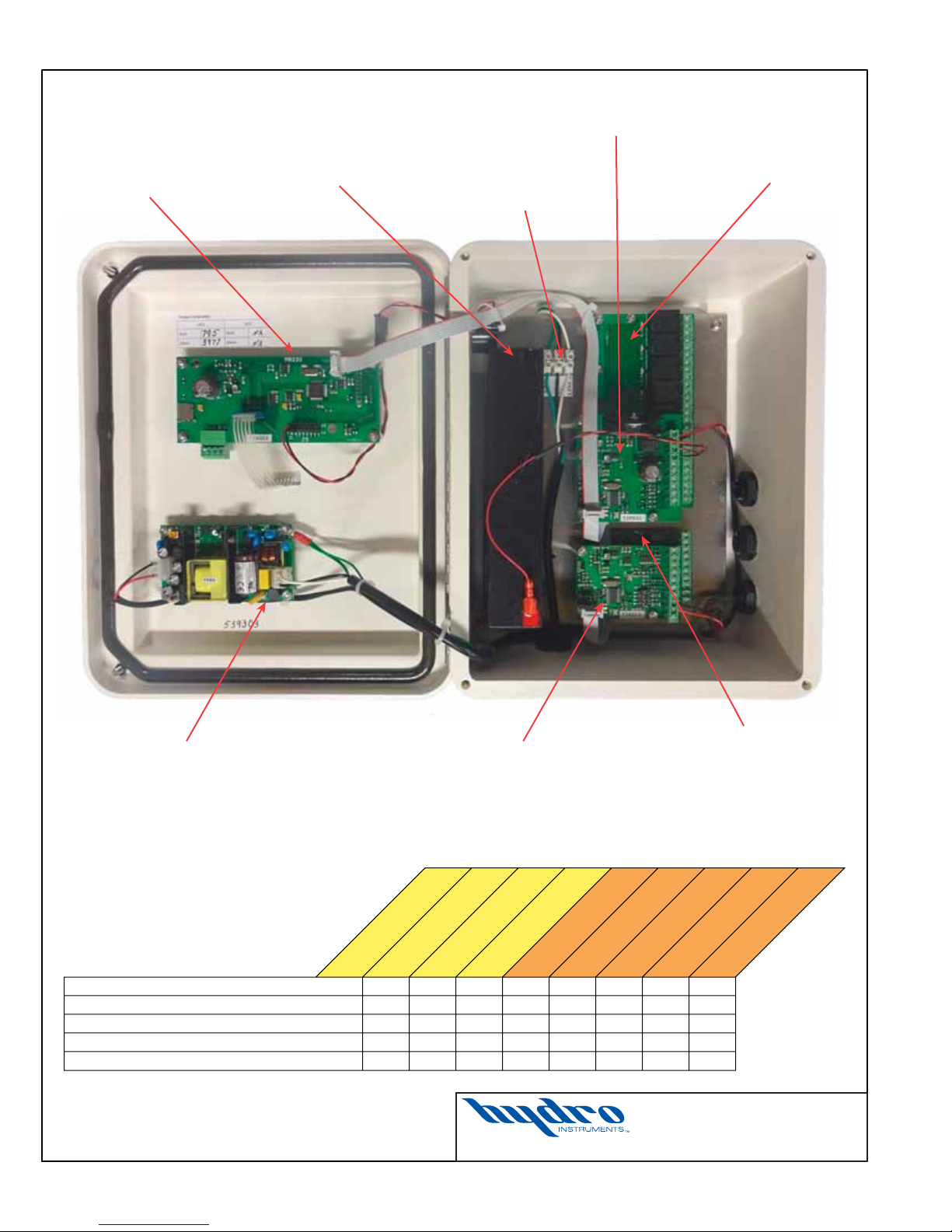
FIGURE 4: GA-180 Controller Electronics
MB220
Display Board
Battery
(CAUTION:
REMOVE BATTERY
BEFORE SHIPPING)
MB141 (CB-THERM)
Thermocouple Board
AC Power
Terminal Block
MB108 (CB-8RELAY)
Eight Relay Board
Power Supply Board MB122 (CB-2X2MA)
Two In, Two Out Board
Photo of a GA-180 unit configured for two sensors with a battery backup.
Some other configuration examples are summarized below.
TABLE 1: Example
Controller Configurations
Maximum Sensors
EXAMPLE
Up To 2 Sensors, No Battery, No Thermocouple 2 No No 1 1 1
Up To 4 Sensors, No Battery, No Thermocouple 4 No No 1 1 2
Up To 4 Sensors, With Battery, No Thermocouple 4 Yes No 1 1 2 1
Up To 4 Sensors, No Battery, With Thermocouple 4 No Yes 1 1 2 1
Up To 2 Sensors, With Battery, With Thermocouple 2 Yes Yes 1 1 1 1 1
Battery?
MB108 (CB-8RELAY)
Thermocouple?
Date: July 2016
Dwg. No. GA-180-CONTROLLER
GA-180 CONTROLLER
6
MB123 (CB-2RELAY)
Eight Relay Board
Two Relay Board
ELECTRONICS
MB122 (CB-2X2MA)
Two In, Two Out Board
MB123 (CB-2RELAY)
Two Relay Board
MB141 (CB-THERM)
MB101 (CB-BAT)
Thermocouple Board
Battery Board
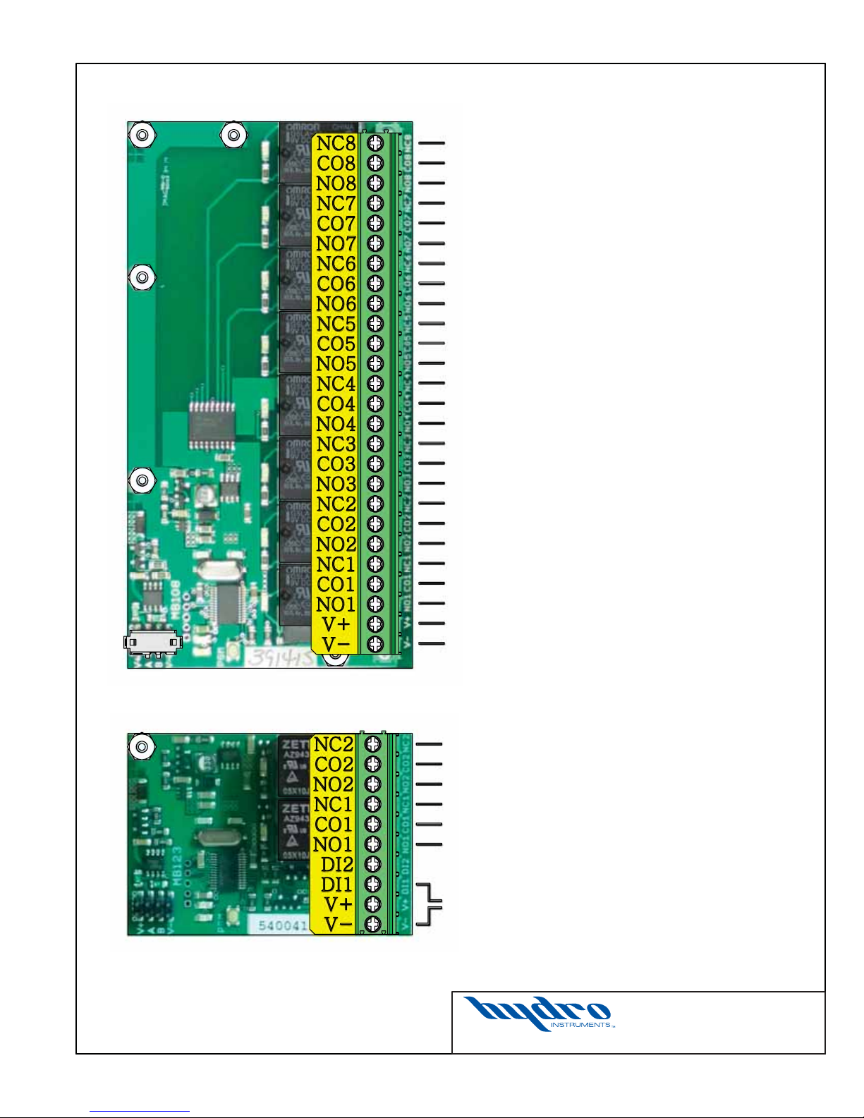
FIGURE 5: Pinout Diagrams for MB108 and MB123
MB108 (CB-8RELAY)
EIGHT RELAY BOARD
Normally Closed 8
Common 8
Normally Open 8
Normally Closed 7
Common 7
Normally Open 7
Normally Closed 6
Common 6
Normally Open 6
Normally Closed 5
Common 5
Normally Open 5
Normally Closed 4
Common 4
Normally Open 4
Normally Closed 3
Common 3
Normally Open 3
Normally Closed 2
Common 2
Normally Open 2
Normally Closed 1
Common 1
Normally Open 1
V+
V–
}
}
}
}
}
}
}
}
RELAY 8
RELAY 7
RELAY 6
RELAY 5
RELAY 4
RELAY 3
RELAY 2
RELAY 1
MB123 (CB-2RELAY)
TWO RELAY BOARD
*Digital Inputs and 4-20mA outputs must also have
appropriate V– (GND) connection. Relays shall be
wired in either a normally open (NO) or normally
closed (NC) arrangement.
Normally Closed 2
Common 2
Normally Open 2
Normally Closed 1
Common 1
Normally Open 1
*Digital Input 1 (Remote Acknowledge)
Date: July 2016
Dwg. No. GA-180-CB1
GA-180 CIRCUIT BOARDS
MB108 & MB123
RELAY 34
}
RELAY 33
}
7
 Loading...