

Page 1

AccuDose Series Proportioner
Models 38741GB & 38751GB
with E-Gap Eductors
Package Should Contain:
1. Proportioner unit.
2. Supply tubing 6.4m total.
3. Foot valve assemblies & weights (5).
4. Discharge tubing for each eductor.
5. Metering tip kits.
6. Mounting anchor kit.
7. Hose hook for 14 LPM eductor.
8. Instruction sheet.
Installation and Operation:
1. Remove cabinet cover. Drill holes for the three wall anchors with an 8mm drill bit, using the cabinet back as a template
for correct spacing of the mounting screws. Install mounting anchors, and then screws in top two anchors. Slide key
holes in cabinet back over screw heads, tighten screws, then install bottom screw. Do not mount more than 1.8 metres
above the bottom of the concentrate container, nor below the highest concentrate level (never mount your
concentrate higher than the proportioner).
2. Select metering tips (up to 4) for the selector valve. (see next two sections) Push each tip firmly into a separate hose
barb extending from the selector valve. A tip with no hole (clear plastic) can be used to block any valve port not being
used. (This may be used for dispensing water only).
3. Attach the chemical suction tube assembly to the selector valve, sliding the open end of each piece of tubing over
one barb on the valve. Make sure suction tubes are on the barb far enough to prevent air from leaking into tube.
4. Slip other end of supply tube through an opening in either side of the cabinet and slide a ceramic weight over the
tube, then push a footvalve into the end of the tube. (Repeat for all eductors.)
5. Place foot valve ends of supply tubes into concentrate containers. REMEMBER TO CHECK FOOT VALVE
STRAINERS PERIODICALLY FOR CLOGGING: CLEAN IF NECESSARY.
6. A short discharge tube is used with the 4 LPM eductor; minimum tube length is 20cm for correct operation. Longer
tubes (1.2 m) are used with a 14 LPM eductor. Do not remove the flooding rings from inside the tubes. Slide end
of tube with flooding ring over eductor discharge outlet. (Repeat for all eductors.) Hooks may be installed on
longertubes to allow discharge tube to hang from dispenser when not in use.
7. Replace cabinet cover. Push the sides in, behind the latch holes, to snap the cover in place. The two screws provided
may be installed in the holes in the cabinet sides to prevent easy removal of cover.
8. Connect water supply hose of at least 13mm ID to water inlet swivel. (Minimum 1.76 Bar pressure, with water running,
is required for correct operation.) Connect opposite end of hose to water supply. Turn water supply on.
9. Push button to start flow of desired water/concentrate solution, and hold until supply tube is primed (filled). Then push
the button whenever dispensing is desired, and release button to stop flow of solution. If you wishto be able to lock
the button in the “on” position: clip or bend the two tabs behind the lower front portion of the button (see diagram).
This allows the button to be pushed fully in and so lock in the “on” position. To unlock, PULL THE BUTTON OUT.
Clip or bend
these tabs to
depress
button into
locked
position.
Page 2
Metering Tip Selection:
The final concentration of the dispensed solution
is related to both the size of the metering tip
opening and the viscosity of the liquid being
siphoned. For water-thin products, the chart at
right can be used as a guideline. If product is
noticeably thicker than water, consult the
Measurement of Concentration Procedure below
to achieve your desired water-to-product ratio.
Because dilution can vary with water temperature
and pressure, actual dilution achieved can only
be ascertained by using the Measurement of
Concentration Procedure. The clear, undrilled
tip is provided to permit drilling to size not listed
should you need a dilution ratio that falls between
standard tip sizes.
NOTE: A 4 LPM eductor is grey; a 14 LPM
eductor is yellow. Refer to parts diagram if
unfamiliar with names of system components.
Dilution Ratio (X:1) where X = Amount of Mixed Solution — Amount of Concentrate Drawn
Dilution Ratio, then, equals X parts water to one part concentrate (X:1). If the test does not yield the desired ratio,
choose a different tip and repeat the test. Alternative methods to this test are 1) pH (using litmus paper), and 2) titration.
Contact your concentrate supplier for further information on these alternative methods and the materials required to
perform them.
AT 40 PSI FOR WATER-THIN PRODUCTS (1.0 CP)
No Tip .187 (3/16) 3:1 6.5:1
Grey .128 (30) 3:1 6.5:1
Black .098 (40) 3:1 7:1
Beige .070 (50) 4:1 10:1
Red .052 (55) 5:1 16:1
White .043 (57) 7:1 20:1
Blue .040 (60) 8:1 24:1
Tan .035 (65) 10:1 30:1
Green .028 (70) 16:1 45:1
Orange .025 (72) 20:1 56:1
Brown .023 (74) 24:1 64:1
Yellow .020 (76) 32:1 90:1
Aqua .018 (77) 38:1 128:1
Purple .014 (79) 64:1 180:1
Pink .010 (87) 128:1 350:1
Amount of Concentrate Drawn
APPROXIMATE DILUTIONS
Orifice Std. Drill
Size Number)
Ratio (per Eductor Flow)
1 GPM 3.5 GPMTip Color
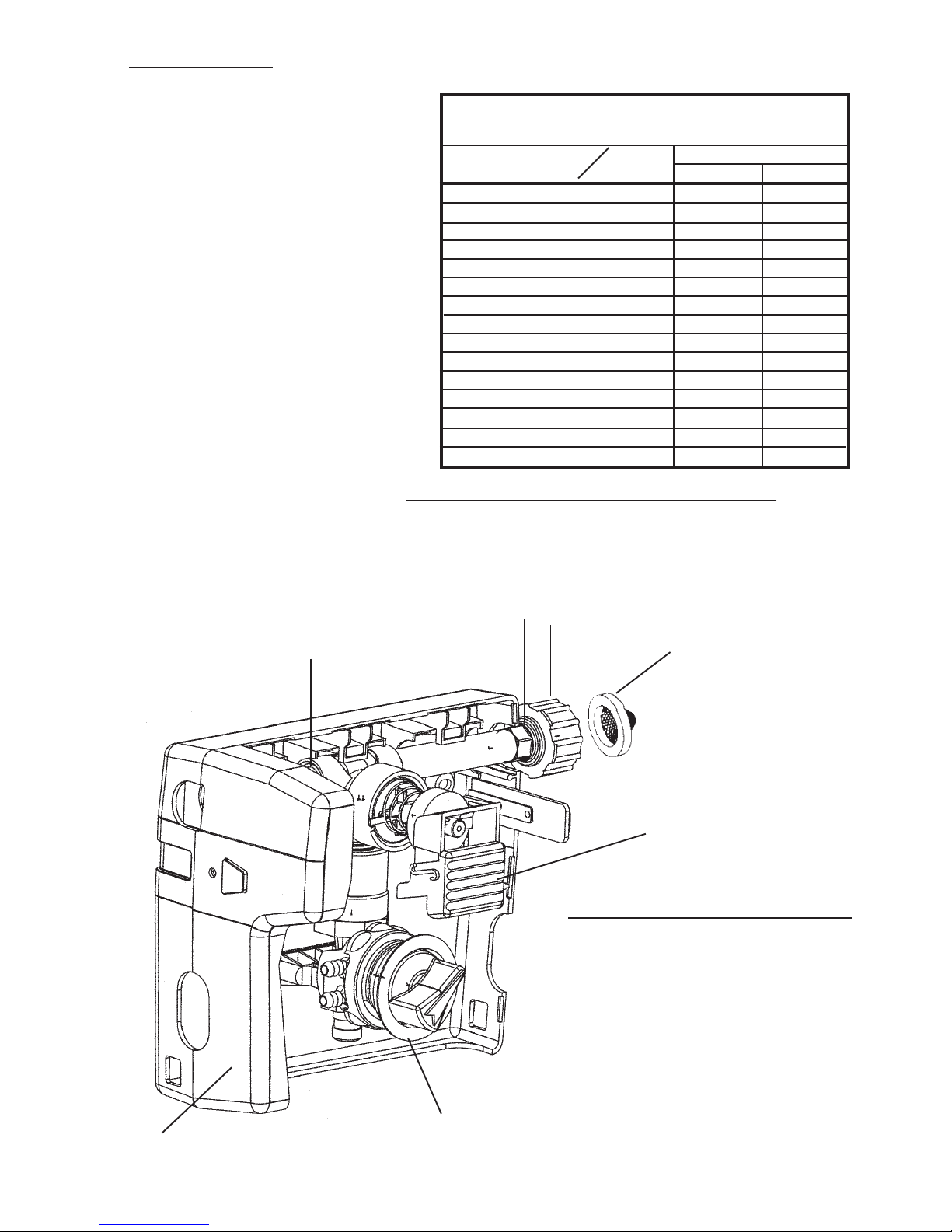
AccuDose Select Parts Diagram List:
4
6
3
2
1
5
Key DescriptionPart No.
1 238100 Strainer washer
2 10082835 Swivel collar (moulded)
3 10082816 Swivel stem (moulded)
10075950 O-ring (two per nipple)
4 10075925 Pipe plug
5 10080710 Button, grey (standard)
10080711 Button, sky blue
10080712 Button, red
10080713 Button, green
10080714 Button, light grey
10080715 Button, yellow
6 10080894 Cabinet
7 10020700 Selector valve grommet
7
10020900 Back up ring for grommet
Page 3
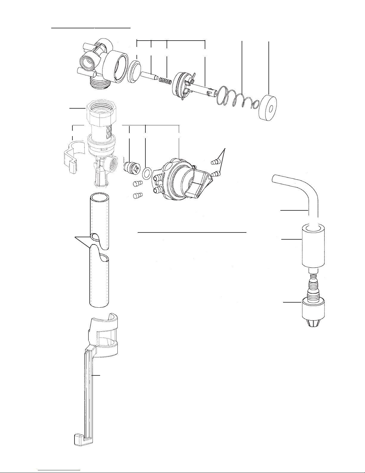
AccuDose Select Parts Diagram:
12a
12b
9
a
b
c d
15
e
g
f
h
16
10 11
Suction tube assembly
(materials for 4 provided)
attach open ends to barbs
on valve.
13a
13b
14
Key DescriptionPart No.
9 10075980 Valve parts kit
a. diaphragm, b. armature,
c. spring, d. valve bonnet
10 10079010 Spring
11 10079000 Magnet
12 290GB 4 LPM eductor assembly (kit)
291GB 14 LPM eductor assembly (kit)
13 a 10088822 4 LPM discharge tube assembly
b 10074815 14 LPM discharge tube assembly
14 10080730 Hose hook, dark grey (standard)
10080731 Hose hook, sky blue
10080732 Hose hook, red
10080733 Hose hook, green
10080734 Hose hook, light grey
10080735 Hose hook, yellow
* Hose hooks are for 14 LPM discharge tubes
15 10080957 Selector replacement kit:
e. support clip f. Suction stub,
g. O-ring, h. selector valve assembly
16 690014 Metering tip (kit)
17 500870 Tubing, 6mm x 2.1m
18 509900 Weight
19 10076301 Footvalve, viton (EPDM also
available order 10076302)
NOT SHOWN:
641750 Screws (cabinet sides)
17
18
19
Page 4
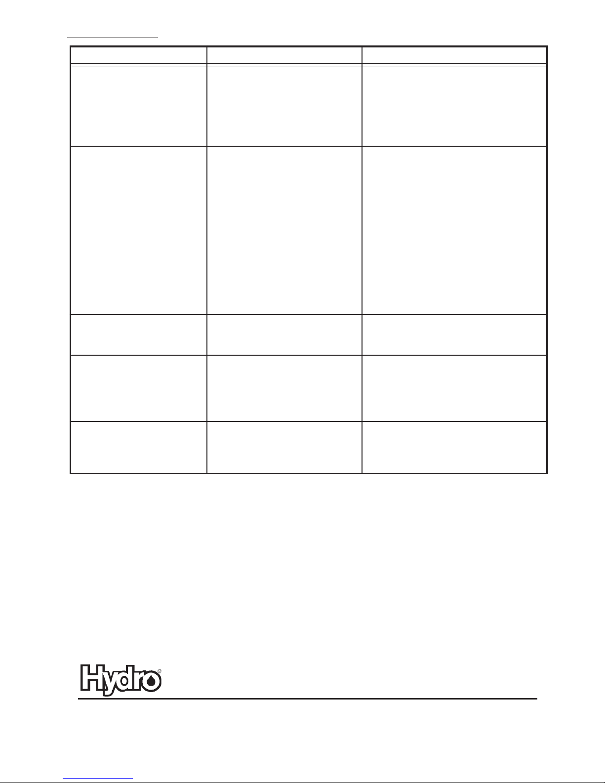
Troubleshooting Chart:
Problem
1. No discharge a. No water a. Open water supply
2. No concentrate draw a. Clogged foot valve a. Clean or replace
3. Excess concentrate draw a. Metering tip not in place a. Press correct tip firmly into barb on
Cause Solution
b. Magnetic valve not functioning b. Install valve parts kit
c. Excessive water pressure c. Install regulator if water pressure
exceeds 4.3 Bar (flowing)
d. Eductor clogged d. Clean* or replace
e. Clogged water inlet strainer e. Disconnect inlet water line and clean
strainer
b. Scale build-up in metering tip b. Clean (descale)* or replace
or eductor
c. Low water pressure c. Minimum 1.76 Bar (with water running)
required to operate unit correctly
d. Discharge tube and/or flooding d. Push tube firmly onto eductor discharge
ring not in place hose barb, or replace tube if it does not
have a flooding ring.
e. Concentrate container empty e. Replace with full container
f. Inlet suction stub not screwed f. Tighten, but do not overtighten
into eductor tightly
g. Clogged water inlet strainer g. Disconnect inlet water line and clean
strainer
h. Air leak in chemical pick-up tube h. Put clamp on tube or replace tube if
brittle
i. Selector out of position i. Ensure selector is in desired position
selector valve
b. Chemical above eductor b. Place concentrate below the eductor
4. Failure of unit to turn off a. Water valve parts dirty or a. Clean* or replace with valve parts kit
5. Excess foaming in discharge a. Air leak in pick-up tube a. Put clamp on tube or replace tube if
* In hard water areas, scale may form inside the discharge end of the eductor, as well as in other areas of the unit which are
exposed to water. This scale may be removed by soaking the eductor in a descaling solution (deliming solution). To remove
an eductor located in the cabinet, firmly grasp water valve and unthread eductor. Replace in same manner. Alternatively, a
scaled eductor can be cleaned (or kept from scaling) by drawing the descaling solution through the unit. Operate the unit with
the suction tube in the descaling solution. Operate the unit until solution is drawn consistently, then flush the unit by drawing
clear water through it for a minute. Replace concentrate container and put suction tube into concentrate.
defective
b. Magnet does not fully return b. Make sure magnet moves freely.
c. Push button stuck c. Remove button and clean cabinet/
button to remove any dirt lodged in slide
recess
brittle
Hydro Systems Europe Ltd, Unit 3 The Sterling Centre, Eastern Road, Bracknell, Berks RG12 2PW UK
Tel: +44 (0)1344 48 88 80
Fax: +44 (0)1344 48 88 79
www. hydrosystemseurope.com
10089611
 Loading...