

Hydro 1221GB, 1222GB, 1223GB, 1224GB, 1225GB User Manual
...
user manual
EvoClean
( 1221GB, 1222GB, 1223GB, 1224GB, 1225GB, 1226GB, 1227GB, 1228GB, 1230GB, 1231GB, 1232GB, 1233GB,
1234GB, 1235GB, 1236GB, 1237GB, 1238GB, 1239GB, 1214RAPAPAC, 1216RAPAPAC, 1234GBAPAC,
1235APAC2, 1235GBAPAC, 1218RAPAPAC, 1218RGBAPAC2)
HYD90099594

Page 2
Hydro Systems Europe 2018
contents
contents 2
introduction 3
Overview 3
1. safety 3
PPE for Cleaning Chemicals 3
Electrical 3
2. description 4
2.1 Intended use 4
2.2 Models 4
3. contents of packaging 5
4. site survey and installation requirements 5
5. installation & connection 6
5.1 Installation Step 1: Site survey & mounting kit 6
5.2 Installation Step 2 : Incoming water supply 7
5.3 Installation Step 3 : Route discharge hose to machine 7
5.4 Installation Step 4 : Routing pick up tubes 7
5.5 Installation Step 5 : Trigger connections 8
5.6 Installation Step 6 : Power 10
5.7 Installation Step 7 : Remote Select (Optional) 10
5.8 Installation Step 8 : Off board controller (Optional) 11
6. setup & programming 11
6.1 Modes of operation 11
6.2 Menu structure 12
6.3 Unit controls 12
6.4 User Screens 12
6.5 Setup & Programming Step 1 : Program controller 13
6.6 Setup & Programming Step 2 : Priming 16
6.7 Setup & Programming Step 3 : Calibration 16
6.8 Alarm function 16
6.9 Formula Editor 17
7. menu structure 17
7.1 Home screen 17
7.2 USB Insert memory stick 18
7.3 Settings screen 19
7.4 Set up screen 20
8. maintenance 22
8.1 Legal Requirements 22
8.2 Advised 22
9. specifications 22
10. troubleshooting 23
11. unit diagram & replacement parts 23
11.1 Replacement parts 25
11.2 Accessory parts 26
12. decommissioning and disposal 26
13. warranty 27
14. WEEE - waste electrical and electronic equipment 27
15. electrical approvals 28
Page 3
Hydro Systems Europe 2018
introduction
1. safety
Overview
Please look at and read these instructions carefully before
starting installation, operation, maintenance and keep for
future reference.
Remove all packaging and check the EvoClean includes all
parts against the Contents of Packaging or damage before
starting installation.
Any alterations made to the EvoClean and fittings will invalidate
the Warranty.
THANK YOU FOR YOUR INTEREST IN OUR PRODUCTS
Please use this equipment carefully and observe all warnings and cautions.
WARNING
Please read precautions thoroughly before operation. Meet all applicable local codes and regulations.
WEAR
Protective clothing and eye wear when dispensing chemicals or other materials or when working in
the vicinity of all chemicals, filling or emptying equipment, or changing metering tips.
ALWAYS
Observe safety and handling instructions of the chemical manufacturer.
Direct discharge away from you or other persons or into approved containers.
Dispense cleaners and chemicals in accordance with manufacturer’s instructions.
Exercise CAUTION when maintaining your equipment.
Reassemble equipment according to instruction procedures.
Be sure all components are firmly screwed or latched into position.
KEEP Equipment clean to maintain proper operation.
• This unit is not to be used with ATEX chemicals
• This unit is not to be used with chemicals outside the temperature of 0-60°C
Do not mix cleaning chemical products.
Electrical
The EvoClean is a low maintenance, venturi-based, water
powered laundry unit. It features an integrated control system
that can be used for applications requiring four, six or eight
products and also offers an integrated flush manifold, ‘out-ofproduct’ alarm and optional remote formula select.
Note: The EvoClean may be referred to as the ‘Dispenser’ or
‘unit’ throughout this manual.
• All mains electrical work must be carried out in accordance
with local and national regulations, and by a qualified
electrician.
• The unit MUST be disconnected from its power source
during cleaning, servicing or when replacing parts.
• The Alarm should only be operated at or within the voltage
specified in this Installation and Manual.
• The installer and user are responsible for ensuring the
installation and operation of this Alarm are in accordance
with this Installation and User Manual and local and
national regulations.

Page 4
Hydro Systems Europe 2018
2. description
The EvoClean (Patent Pending GB1708496.3) is a low maintenance, venturi-based, water-powered laundry unit. It features an
integrated control system that can either be supplied on-board the unit or off-board within a housing. The EvoClean can be
used for applications requiring up to four, six or eight products and also offers an integrated flush manifold, ‘out-of-product’
alarm, optional remote formula select and downloadable reports. This guide contains instructions for installing, programming,
operating and troubleshooting the EvoClean. For further information and the option to download the PC formula editor please
navigate to:
http://hydrosystemseurope.com/product/evoclean/
2.1 Intended Use
• The EvoClean is intended for use in industrial applications. It is not suitable for domestic use and it must not be
used outside of its intended use.
• The product must only be used for washing and rinsing of laundry that are marked accordingly. The manufacturer
waives any responsibility arisen from incorrect usage or transportation.
2.2 EMEA models:
• 1221GB – EvoClean 2, 6 Product Unit – Low Flow, RFS
• 1222GB – EvoClean 2, 6 Product Unit – Low Flow, Off BC
• 1223GB – EvoClean 2, 6 Product Unit – High Flow, Off BC
• 1224GB – EvoClean 2, 6 Product Unit – High Flow
• 1225GB – EvoClean 2, 4 Product Unit – Low Flow, Off BC
• 1226GB – EvoClean 2, 4 Product Unit – High Flow, Off BC
• 1227GB – EvoClean 2, 4 Product Unit – Low Flow
• 1228GB – EvoClean 2, 4 Product Unit – High Flow
• 1230GB – EvoClean 2, 8 Product Unit – Low Flow, Off BC
• 1231GB – EvoClean 2, 8 Product Unit – High Flow, Off BC
• 1232GB – EvoClean 2, 8 Product Unit – Low Flow
• 1233GB – EvoClean 2, 8 Product Unit – High Flow
• 1234GB – EvoClean 2, 6 product unit – Low flow, RFS
• 1235GB – EvoClean 2, 6 product unit – High flow, RFS
• 1236GB – EvoClean 2, 4 product unit – Low flow, RFS
• 1237GB – EvoClean 2, 4 product unit – High flow, RFS
• 1238GB – EvoClean 2, 8 product unit – Low flow, RFS
• 1239GB – EvoClean 2, 8 product unit – High flow, RFS
APAC models:
• 1214RAPAPAC – EvoClean 2, 4 Product Unit – Low Flow, RFS
• 1216RAPAPAC – EvoClean 2, 4 Product Unit – High Flow, RFS
• 1234GBAPAC – EvoClean 2, 6 Product Unit – Low Flow, RFS
• 1235APAC2 – EvoClean 2, 6 Product Unit – High Flow, RFS
• 1235GBAPAC – EvoClean 2, 6 Product Unit – High Flow, RFS, EP
• 1218RAPAPAC – EvoClean 2, 8 Product Unit – High Flow, RFS
• 1218RGBAPAC2 – EvoClean 2, 8 Product Unit – High Flow, RFS, EP
*other versions are available on request
Page 5
Hydro Systems Europe 2018
4. site survey & installation requirements
CAUTION
Before an installation takes place it is advisable to complete a site survey to ensure the EvoClean can be installed
in a position that meets all of the requirements listed below.
• Unit is to be installed by a trained technician; all local and national electrical and water regulations are to be
observed.
• Unit must not be installed near areas that suffer excess temperature changes, direct sunlight, frost or moisture
of any kind.
• Area must be free of high levels of electrical noise.
• Ensure the unit can be mounted in an accessible position above the height of the required discharge location.
• Unit must be mounted on a suitable wall, that is flat and perpendicular to the floor.
• The unit location should be well lit for any maintenance and free of high levels of dust / air particulates.
• Scheduled maintenance should be carried out on the dispenser at least once per year.
• It is a legal requirement if the EvoClean is supplied from the water mains, that a backflow device offering
protection equal or higher than the products being dispensed to prevent back siphoning of non-potable water
into the water mains. If used, hose sets used to connect the EvoClean to the mains water supply must also be
compliant with IEC 61770.
3. contents of packaging
• EvoClean Unit
• Accessory Kit :
Wall Mount Brackets
Clips
Screws
Wall Plugs
• Chemical Pickup tube and Install Kit*
• Remote Formula Select*
• Calibration Cylinder*
• Backflow Device*
*Do not come as standard - Optional extra.
WARNING
Ensure the incoming water supply hose is supported to prevent unnecessary stress on the inlet
fitting.
1. Connect incoming water supply using fittings provided. This will either be a 3/4” female Garden Hose fitting, or a
1/2” O.D.
2. A locally approved back-flow prevention device (not provided) may be required for sale and legal operation.
Page 6
Hydro Systems Europe 2018
5.1.4.
Secure the dispenser at the bottom, with the remaining screw provided.
5.1.5.
If the unit is configured with the off-board controller, this can be mounted using the hook and loop tape supplied.
Note: Please secure any cables so as not to create a hazard for the operator.
5. installation & connection
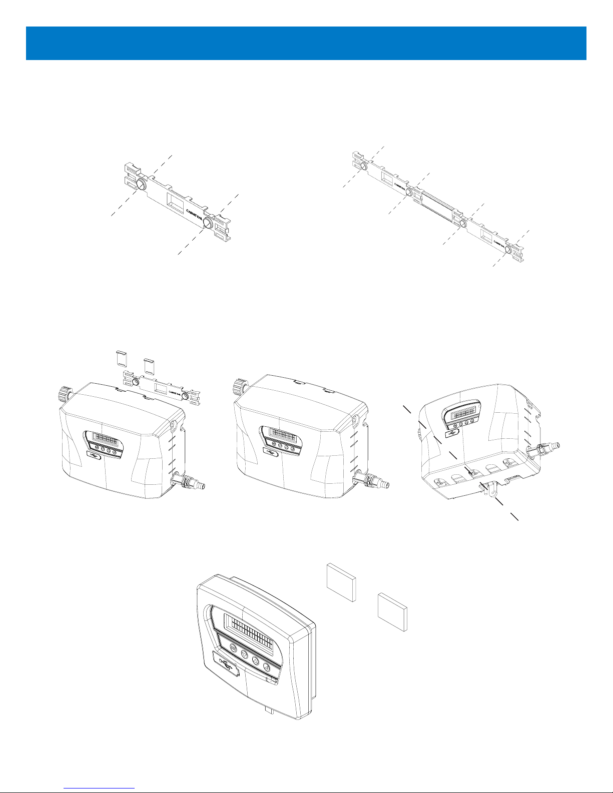
5.1.1.
Choose a location near to the laundry machine. Use the mounting bracket to mark the appropriate locations for the
mounting hardware. Use the mounting bracket as a hole template to mark the securing holes.
5.1.2.
Wall anchors are provided, please ensure they are appropriate to the wall/surface being mounted to.
5.1.3
Mount the dispenser onto the mounting bracket. Push down the clips to secure the unit.
5.1. Installation Step 1: Site Survey & Mounting Kit
Mounting bracket: 4 product unit (Left), or 6/8 product unit including joins (Right)
Page 7
Hydro Systems Europe 2018
5.2.1.
Connect incoming water supply to EvoClean using fittings provided. This will either be a ¾’’ Female BSP swivel, or
15mm push-fit. Ensure the incoming water supply hose is supported so as not to create unnecessary force on the inlet.
5.2.2.
It is a legal requirement, if the unit is supplied from the water mains, that a backflow device is installed offering protection
equal or higher than the chemical class being used. This is to prevent back siphoning of non-potable substances into
the water mains.
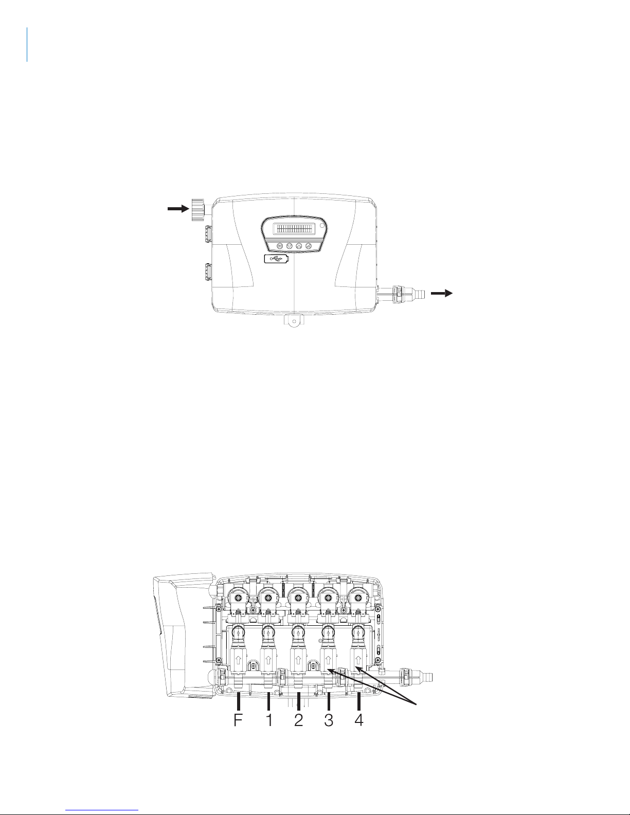
Note: It is possible to have the water inlet on either side of the dispenser but the outlet will always need to be on the right.
Water Outlet
Water Inlet
5.2. Installation Step 2: Incoming Water Supply
5.2.3.
Hose sets used to connect the EvoClean to the mains water supply must also be compliant with IEC 61770.
Note: It is recommended that the delivery hose between the EvoClean and the washing machine be as short as possible. Any
vertical routes should be kept to a minimum.
5.3.1.
Connect outlet (see above) to the washing machine using 12.7mm (½’’) or 13mm ID Flexible braided PVC Hose.
5.3.2.
Secure PVC hose to barb with cable tie.
5.3. Installation Step 3: Route Discharge Hose to Machine
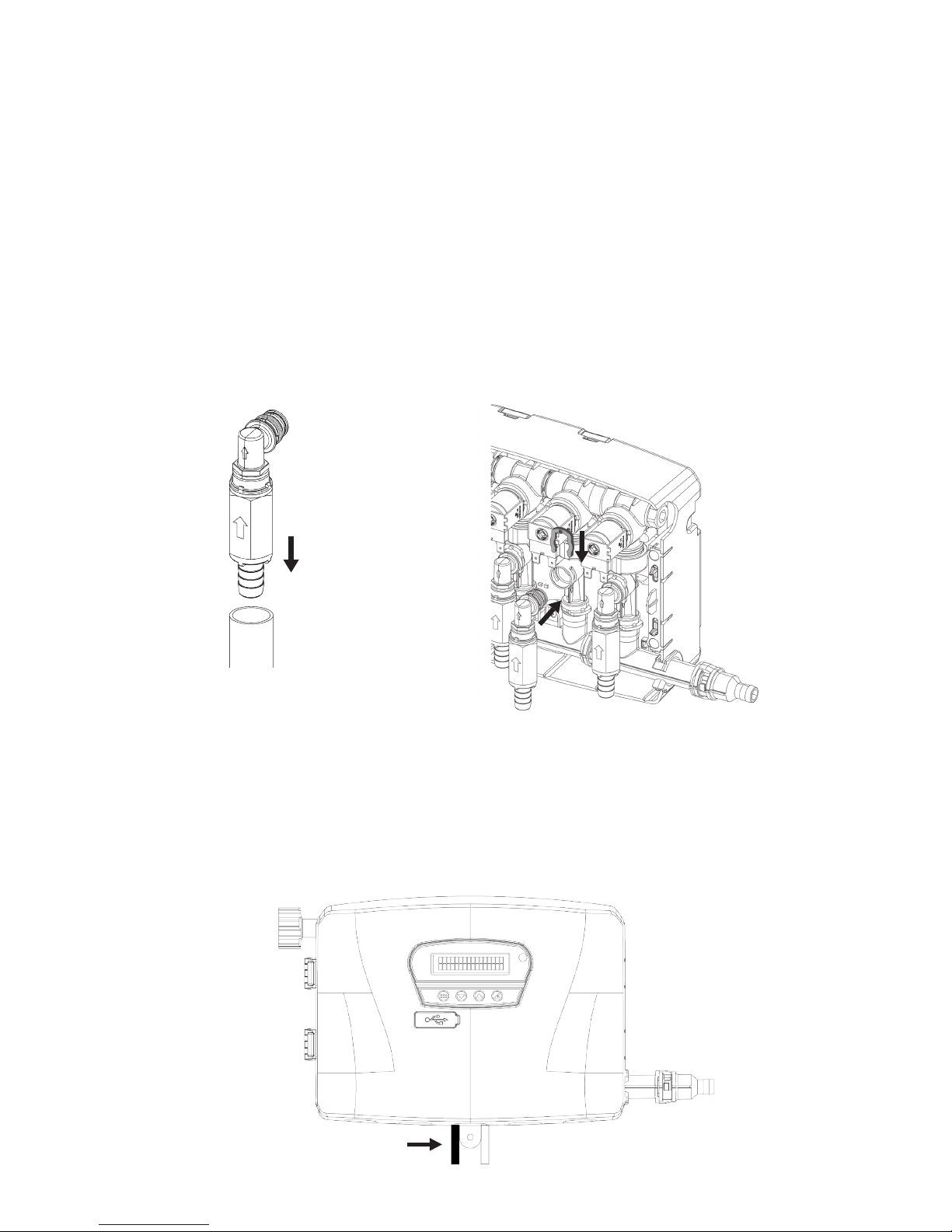
Check Valves
5.4. Installation Step 4: Routing Pickup Tubes
Note: The check valves are supplied detached in a bag with the unit. To prevent damage, do not install hoses to the check
valve while connected to the manifold.
Page 8
Hydro Systems Europe 2018
5.4.5.
Take chemical container lid and drill 20mm (¾’’) hole for PVC Hose to pass through, ensure tube is not a tight fit (to
avoid vacuum).
Note: Do not drill lid when screwed onto chemical container to avoid swarf.
5.4.6.
Replace lid on container, and place the inlet tube into the container.
5.5. Installation Step 5: Trigger Connections
5.5.1.
The EvoClean uses the following trigger signal inputs.
5.4.1.
Eductors run from left to right in the following order:
In 4 Product units (Single cabinet)
• F (Flush) 1, 2, 3, 4
In 6 product units (Single cabinet)
• F (Flush) 1, 2, 3, 4, 5, 6
In 8 Product units (Twin cabinet)
• F (Flush) 1, 2, 3, 4, 5, 6, 7, 8.
Note: Flush - Do not connect any tube to this position.
5.4.2.
Measure the distance from the Eductor to the base of the chemical container.
5.4.3.
Cut the 12.7mm (½’’) or 13mm ID Flexible PVC Hose tube to length.
Note: Alternative hose options are available. Contact Hydro Systems for further information.
5.4.4.
Push the PVC hose on to the detached check valve and secure with cable tie, then push the elbow into the eductor
and secure with the clip, as shown in the diagram on the next page.

Page 9
Hydro Systems Europe 2018
10-way harness (4, 6 and 8 product units)
Trigger Supply Signal (+) Signal Common (-) Connected in RELAY
mode:
Connected in NORMAL
mode:
Trigger 1 Black Red Solenoid 1 Pre-Wash
Trigger 2 Hot Green Orange Solenoid 2 Main-Wash
Trigger 2 Cold White Orange Solenoid 2 Main-Wash
Trigger 3 Spare Blue Brown Solenoid 3 SPARE
Trigger 4 Yellow Purple Solenoid 4 Final Rinse
Trigger 5 Grey Purple Solenoid 5
AFS mode*
* See 5.5.3 - Auto Formula Select
3-way harness (6 and 8 product units only)
Trigger Supply Signal (+) Signal Common (-) Connected in RELAY
mode:
Connected in NORMAL
mode:
Trigger 6 Black Purple Solenoid 6 -
Trigger 7 Red Purple Solenoid 7 -
Trigger 8 White Purple Solenoid 8 -
5.5.2
All signal inputs are optically isolated high impedance input circuits. Supply signal voltages may range from 24-240
VAC, 50-60 Hz (20 mA maximum draw) or 12-24 VDC, (5 mA maximum draw) that accommodate the range typically
found in most washing machines. Each signal input connects to a signal input wire and the common. With DC signals,
polarity must be observed. The signals should be positive voltages (+). The Common is negative (-).
5.5.3. Auto Formula Select (AFS)
When operating in ‘normal mode’ the formula can be selected automatically upon receipt of a signal from the washer
extractor. The formula selection is based on the length of signal received. The signal length is calculated as 2x the
formula number being selected. For instance, a 10 second signal will result in formula 5 being selected, a 20 second
signal will result in formula 10 being selected and so on. The same logic is applicable for all of the Evoclean’s 21
formulas.
AFS mode does not need to be selected as trigger 5 is dedicated to AFS when the unit is set to ‘normal mode’. If AFS
mode is not required then trigger 5 should not be connected and the wires isolated as discussed in 5.5.5.
When a signal is received on trigger 5 the unit will show ‘AFS Active’ on screen. Once this signal has been received the
unit will change formula and will then await signals once a wash cycle has been initiated. If the formula that has been
selected is not ‘enabled’ the unit will show an error message and the formula will not change. Also, if the unit is part
way through a cycle a signal on trigger 5 will be ignored until the unit has reset.
Note: The tolerance on signal length is +/- 1 second.
5.5.4
Use appropriate terminal connectors to connect the signal wires to the laundry machine.
5.5.5
If one or more trigger wires are not used, they do not need to be connected but should be suitably isolated and
secured.
 Loading...