

Page 1

user manual
EvoClean
( 1221GB, 1222GB, 1223GB, 1224GB, 1225GB, 1226GB, 1227GB, 1228GB, 1230GB, 1231GB, 1232GB, 1233GB,
1234GB, 1235GB, 1236GB, 1237GB, 1238GB, 1239GB, 1214RAPAPAC, 1216RAPAPAC, 1234GBAPAC,
1235APAC2, 1235GBAPAC, 1218RAPAPAC, 1218RGBAPAC2)
HYD90099594
Page 2

Page 2
Hydro Systems Europe 2018
contents
contents 2
introduction 3
Overview 3
1. safety 3
PPE for Cleaning Chemicals 3
Electrical 3
2. description 4
2.1 Intended use 4
2.2 Models 4
3. contents of packaging 5
4. site survey and installation requirements 5
5. installation & connection 6
5.1 Installation Step 1: Site survey & mounting kit 6
5.2 Installation Step 2 : Incoming water supply 7
5.3 Installation Step 3 : Route discharge hose to machine 7
5.4 Installation Step 4 : Routing pick up tubes 7
5.5 Installation Step 5 : Trigger connections 8
5.6 Installation Step 6 : Power 10
5.7 Installation Step 7 : Remote Select (Optional) 10
5.8 Installation Step 8 : Off board controller (Optional) 11
6. setup & programming 11
6.1 Modes of operation 11
6.2 Menu structure 12
6.3 Unit controls 12
6.4 User Screens 12
6.5 Setup & Programming Step 1 : Program controller 13
6.6 Setup & Programming Step 2 : Priming 16
6.7 Setup & Programming Step 3 : Calibration 16
6.8 Alarm function 16
6.9 Formula Editor 17
7. menu structure 17
7.1 Home screen 17
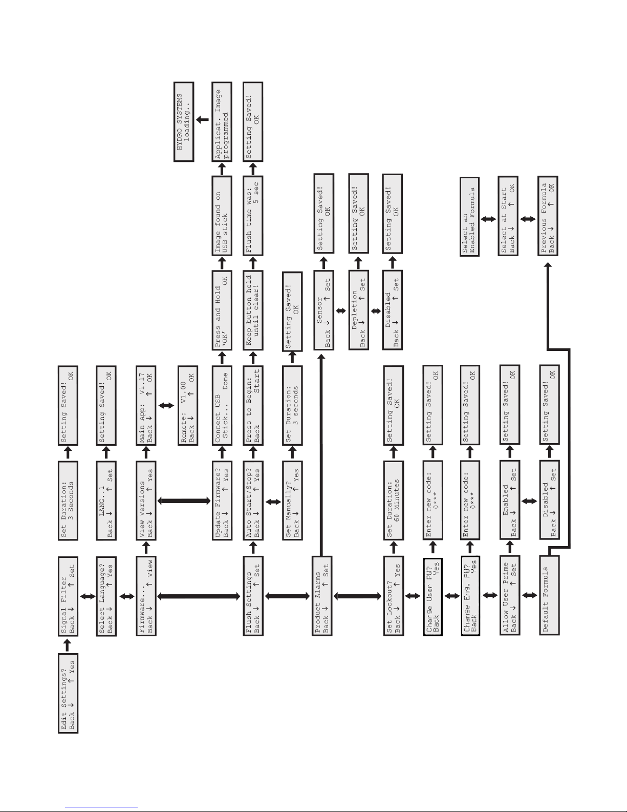
7.2 USB Insert memory stick 18
7.3 Settings screen 19
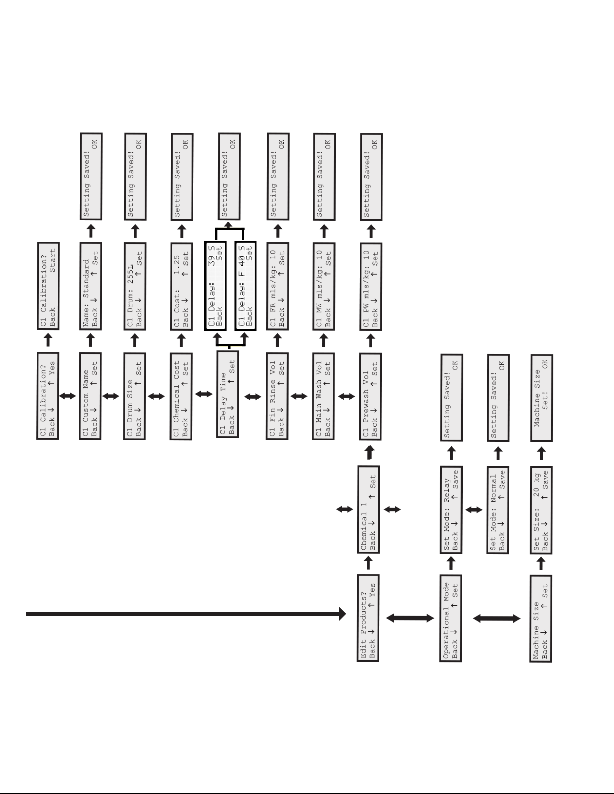
7.4 Set up screen 20
8. maintenance 22
8.1 Legal Requirements 22
8.2 Advised 22
9. specifications 22
10. troubleshooting 23
11. unit diagram & replacement parts 23
11.1 Replacement parts 25
11.2 Accessory parts 26
12. decommissioning and disposal 26
13. warranty 27
14. WEEE - waste electrical and electronic equipment 27
15. electrical approvals 28
Page 3
Page 3
Hydro Systems Europe 2018
introduction
1. safety
Overview
Please look at and read these instructions carefully before
starting installation, operation, maintenance and keep for
future reference.
Remove all packaging and check the EvoClean includes all
parts against the Contents of Packaging or damage before
starting installation.
Any alterations made to the EvoClean and fittings will invalidate
the Warranty.
THANK YOU FOR YOUR INTEREST IN OUR PRODUCTS
Please use this equipment carefully and observe all warnings and cautions.
WARNING
Please read precautions thoroughly before operation. Meet all applicable local codes and regulations.
WEAR
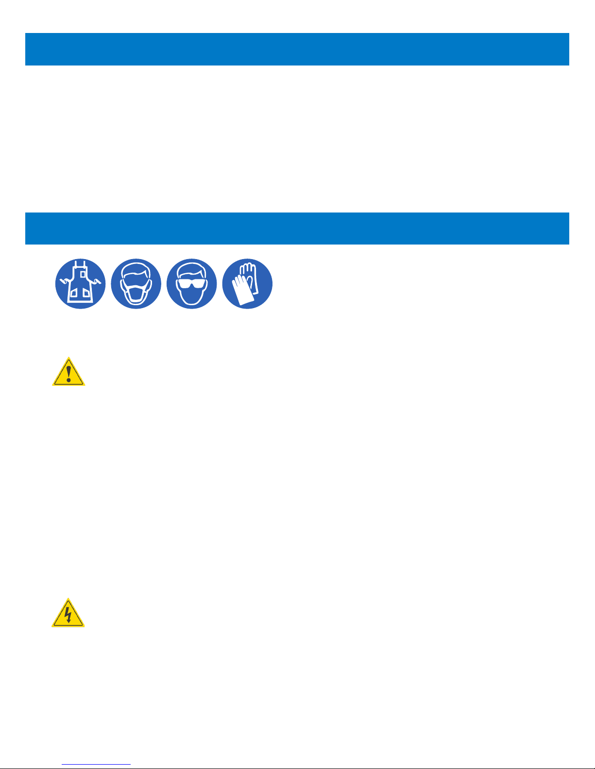
Protective clothing and eye wear when dispensing chemicals or other materials or when working in
the vicinity of all chemicals, filling or emptying equipment, or changing metering tips.
ALWAYS
Observe safety and handling instructions of the chemical manufacturer.
Direct discharge away from you or other persons or into approved containers.
Dispense cleaners and chemicals in accordance with manufacturer’s instructions.
Exercise CAUTION when maintaining your equipment.
Reassemble equipment according to instruction procedures.
Be sure all components are firmly screwed or latched into position.
KEEP Equipment clean to maintain proper operation.
• This unit is not to be used with ATEX chemicals
• This unit is not to be used with chemicals outside the temperature of 0-60°C
Do not mix cleaning chemical products.
Electrical
The EvoClean is a low maintenance, venturi-based, water
powered laundry unit. It features an integrated control system
that can be used for applications requiring four, six or eight
products and also offers an integrated flush manifold, ‘out-ofproduct’ alarm and optional remote formula select.
Note: The EvoClean may be referred to as the ‘Dispenser’ or
‘unit’ throughout this manual.
• All mains electrical work must be carried out in accordance
with local and national regulations, and by a qualified
electrician.
• The unit MUST be disconnected from its power source
during cleaning, servicing or when replacing parts.
• The Alarm should only be operated at or within the voltage
specified in this Installation and Manual.
• The installer and user are responsible for ensuring the
installation and operation of this Alarm are in accordance
with this Installation and User Manual and local and
national regulations.
Page 4

Page 4
Hydro Systems Europe 2018
2. description
The EvoClean (Patent Pending GB1708496.3) is a low maintenance, venturi-based, water-powered laundry unit. It features an
integrated control system that can either be supplied on-board the unit or off-board within a housing. The EvoClean can be
used for applications requiring up to four, six or eight products and also offers an integrated flush manifold, ‘out-of-product’
alarm, optional remote formula select and downloadable reports. This guide contains instructions for installing, programming,
operating and troubleshooting the EvoClean. For further information and the option to download the PC formula editor please
navigate to:
http://hydrosystemseurope.com/product/evoclean/
2.1 Intended Use
• The EvoClean is intended for use in industrial applications. It is not suitable for domestic use and it must not be
used outside of its intended use.
• The product must only be used for washing and rinsing of laundry that are marked accordingly. The manufacturer
waives any responsibility arisen from incorrect usage or transportation.
2.2 EMEA models:
• 1221GB – EvoClean 2, 6 Product Unit – Low Flow, RFS
• 1222GB – EvoClean 2, 6 Product Unit – Low Flow, Off BC
• 1223GB – EvoClean 2, 6 Product Unit – High Flow, Off BC
• 1224GB – EvoClean 2, 6 Product Unit – High Flow
• 1225GB – EvoClean 2, 4 Product Unit – Low Flow, Off BC
• 1226GB – EvoClean 2, 4 Product Unit – High Flow, Off BC
• 1227GB – EvoClean 2, 4 Product Unit – Low Flow
• 1228GB – EvoClean 2, 4 Product Unit – High Flow
• 1230GB – EvoClean 2, 8 Product Unit – Low Flow, Off BC
• 1231GB – EvoClean 2, 8 Product Unit – High Flow, Off BC
• 1232GB – EvoClean 2, 8 Product Unit – Low Flow
• 1233GB – EvoClean 2, 8 Product Unit – High Flow
• 1234GB – EvoClean 2, 6 product unit – Low flow, RFS
• 1235GB – EvoClean 2, 6 product unit – High flow, RFS
• 1236GB – EvoClean 2, 4 product unit – Low flow, RFS
• 1237GB – EvoClean 2, 4 product unit – High flow, RFS
• 1238GB – EvoClean 2, 8 product unit – Low flow, RFS
• 1239GB – EvoClean 2, 8 product unit – High flow, RFS
APAC models:
• 1214RAPAPAC – EvoClean 2, 4 Product Unit – Low Flow, RFS
• 1216RAPAPAC – EvoClean 2, 4 Product Unit – High Flow, RFS
• 1234GBAPAC – EvoClean 2, 6 Product Unit – Low Flow, RFS
• 1235APAC2 – EvoClean 2, 6 Product Unit – High Flow, RFS
• 1235GBAPAC – EvoClean 2, 6 Product Unit – High Flow, RFS, EP
• 1218RAPAPAC – EvoClean 2, 8 Product Unit – High Flow, RFS
• 1218RGBAPAC2 – EvoClean 2, 8 Product Unit – High Flow, RFS, EP
*other versions are available on request
Page 5
Page 5
Hydro Systems Europe 2018
4. site survey & installation requirements
CAUTION
Before an installation takes place it is advisable to complete a site survey to ensure the EvoClean can be installed
in a position that meets all of the requirements listed below.
• Unit is to be installed by a trained technician; all local and national electrical and water regulations are to be
observed.
• Unit must not be installed near areas that suffer excess temperature changes, direct sunlight, frost or moisture
of any kind.
• Area must be free of high levels of electrical noise.
• Ensure the unit can be mounted in an accessible position above the height of the required discharge location.
• Unit must be mounted on a suitable wall, that is flat and perpendicular to the floor.
• The unit location should be well lit for any maintenance and free of high levels of dust / air particulates.
• Scheduled maintenance should be carried out on the dispenser at least once per year.
• It is a legal requirement if the EvoClean is supplied from the water mains, that a backflow device offering
protection equal or higher than the products being dispensed to prevent back siphoning of non-potable water
into the water mains. If used, hose sets used to connect the EvoClean to the mains water supply must also be
compliant with IEC 61770.
3. contents of packaging
• EvoClean Unit
• Accessory Kit :
Wall Mount Brackets
Clips
Screws
Wall Plugs
• Chemical Pickup tube and Install Kit*
• Remote Formula Select*
• Calibration Cylinder*
• Backflow Device*
*Do not come as standard - Optional extra.
WARNING
Ensure the incoming water supply hose is supported to prevent unnecessary stress on the inlet
fitting.
1. Connect incoming water supply using fittings provided. This will either be a 3/4” female Garden Hose fitting, or a
1/2” O.D.
2. A locally approved back-flow prevention device (not provided) may be required for sale and legal operation.
Page 6
Page 6
Hydro Systems Europe 2018
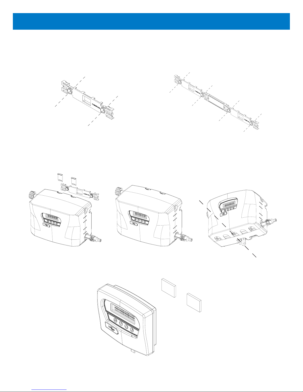
5.1.4.
Secure the dispenser at the bottom, with the remaining screw provided.
5.1.5.
If the unit is configured with the off-board controller, this can be mounted using the hook and loop tape supplied.
Note: Please secure any cables so as not to create a hazard for the operator.
5. installation & connection
5.1.1.
Choose a location near to the laundry machine. Use the mounting bracket to mark the appropriate locations for the
mounting hardware. Use the mounting bracket as a hole template to mark the securing holes.
5.1.2.
Wall anchors are provided, please ensure they are appropriate to the wall/surface being mounted to.
5.1.3
Mount the dispenser onto the mounting bracket. Push down the clips to secure the unit.
5.1. Installation Step 1: Site Survey & Mounting Kit
Mounting bracket: 4 product unit (Left), or 6/8 product unit including joins (Right)
Page 7
Page 7
Hydro Systems Europe 2018
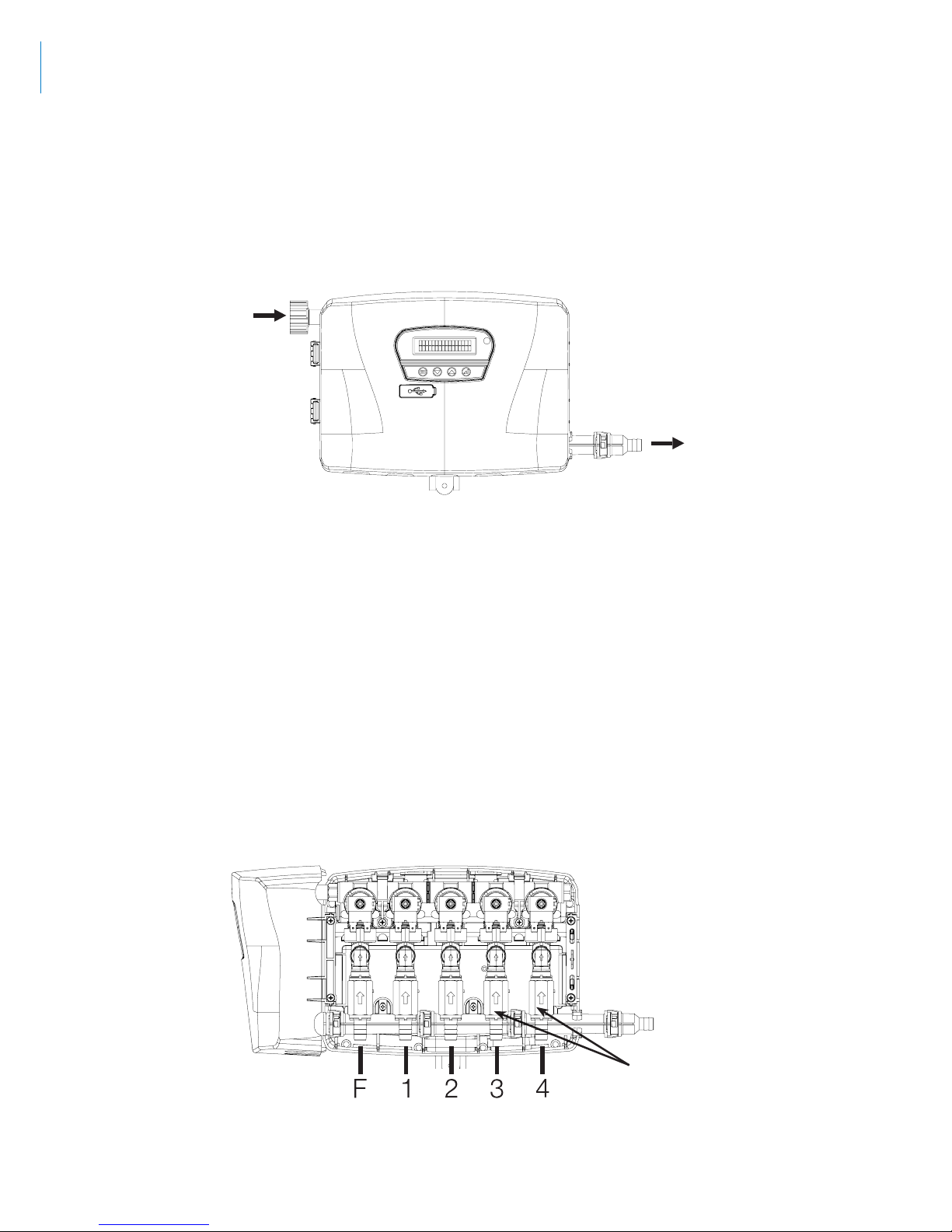
5.2.1.
Connect incoming water supply to EvoClean using fittings provided. This will either be a ¾’’ Female BSP swivel, or
15mm push-fit. Ensure the incoming water supply hose is supported so as not to create unnecessary force on the inlet.
5.2.2.
It is a legal requirement, if the unit is supplied from the water mains, that a backflow device is installed offering protection
equal or higher than the chemical class being used. This is to prevent back siphoning of non-potable substances into
the water mains.
Note: It is possible to have the water inlet on either side of the dispenser but the outlet will always need to be on the right.
Water Outlet
Water Inlet
5.2. Installation Step 2: Incoming Water Supply
5.2.3.
Hose sets used to connect the EvoClean to the mains water supply must also be compliant with IEC 61770.
Note: It is recommended that the delivery hose between the EvoClean and the washing machine be as short as possible. Any
vertical routes should be kept to a minimum.
5.3.1.
Connect outlet (see above) to the washing machine using 12.7mm (½’’) or 13mm ID Flexible braided PVC Hose.
5.3.2.
Secure PVC hose to barb with cable tie.
5.3. Installation Step 3: Route Discharge Hose to Machine
Check Valves
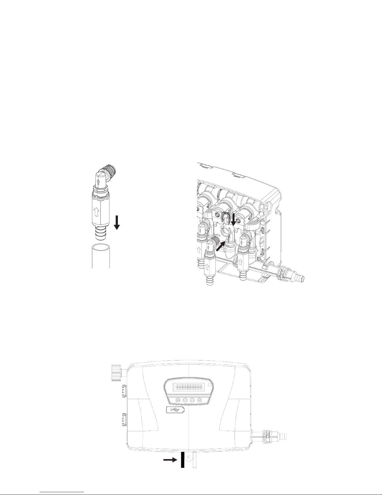
5.4. Installation Step 4: Routing Pickup Tubes
Note: The check valves are supplied detached in a bag with the unit. To prevent damage, do not install hoses to the check
valve while connected to the manifold.
Page 8
Page 8
Hydro Systems Europe 2018
5.4.5.
Take chemical container lid and drill 20mm (¾’’) hole for PVC Hose to pass through, ensure tube is not a tight fit (to
avoid vacuum).
Note: Do not drill lid when screwed onto chemical container to avoid swarf.
5.4.6.
Replace lid on container, and place the inlet tube into the container.
5.5. Installation Step 5: Trigger Connections
5.5.1.
The EvoClean uses the following trigger signal inputs.
5.4.1.
Eductors run from left to right in the following order:
In 4 Product units (Single cabinet)
• F (Flush) 1, 2, 3, 4
In 6 product units (Single cabinet)
• F (Flush) 1, 2, 3, 4, 5, 6
In 8 Product units (Twin cabinet)
• F (Flush) 1, 2, 3, 4, 5, 6, 7, 8.
Note: Flush - Do not connect any tube to this position.
5.4.2.
Measure the distance from the Eductor to the base of the chemical container.
5.4.3.
Cut the 12.7mm (½’’) or 13mm ID Flexible PVC Hose tube to length.
Note: Alternative hose options are available. Contact Hydro Systems for further information.
5.4.4.
Push the PVC hose on to the detached check valve and secure with cable tie, then push the elbow into the eductor
and secure with the clip, as shown in the diagram on the next page.
Page 9

Page 9
Hydro Systems Europe 2018
10-way harness (4, 6 and 8 product units)
Trigger Supply Signal (+) Signal Common (-) Connected in RELAY
mode:
Connected in NORMAL
mode:
Trigger 1 Black Red Solenoid 1 Pre-Wash
Trigger 2 Hot Green Orange Solenoid 2 Main-Wash
Trigger 2 Cold White Orange Solenoid 2 Main-Wash
Trigger 3 Spare Blue Brown Solenoid 3 SPARE
Trigger 4 Yellow Purple Solenoid 4 Final Rinse
Trigger 5 Grey Purple Solenoid 5
AFS mode*
* See 5.5.3 - Auto Formula Select
3-way harness (6 and 8 product units only)
Trigger Supply Signal (+) Signal Common (-) Connected in RELAY
mode:
Connected in NORMAL
mode:
Trigger 6 Black Purple Solenoid 6 -
Trigger 7 Red Purple Solenoid 7 -
Trigger 8 White Purple Solenoid 8 -
5.5.2
All signal inputs are optically isolated high impedance input circuits. Supply signal voltages may range from 24-240
VAC, 50-60 Hz (20 mA maximum draw) or 12-24 VDC, (5 mA maximum draw) that accommodate the range typically
found in most washing machines. Each signal input connects to a signal input wire and the common. With DC signals,
polarity must be observed. The signals should be positive voltages (+). The Common is negative (-).
5.5.3. Auto Formula Select (AFS)
When operating in ‘normal mode’ the formula can be selected automatically upon receipt of a signal from the washer
extractor. The formula selection is based on the length of signal received. The signal length is calculated as 2x the
formula number being selected. For instance, a 10 second signal will result in formula 5 being selected, a 20 second
signal will result in formula 10 being selected and so on. The same logic is applicable for all of the Evoclean’s 21
formulas.
AFS mode does not need to be selected as trigger 5 is dedicated to AFS when the unit is set to ‘normal mode’. If AFS
mode is not required then trigger 5 should not be connected and the wires isolated as discussed in 5.5.5.
When a signal is received on trigger 5 the unit will show ‘AFS Active’ on screen. Once this signal has been received the
unit will change formula and will then await signals once a wash cycle has been initiated. If the formula that has been
selected is not ‘enabled’ the unit will show an error message and the formula will not change. Also, if the unit is part
way through a cycle a signal on trigger 5 will be ignored until the unit has reset.
Note: The tolerance on signal length is +/- 1 second.
5.5.4
Use appropriate terminal connectors to connect the signal wires to the laundry machine.
5.5.5
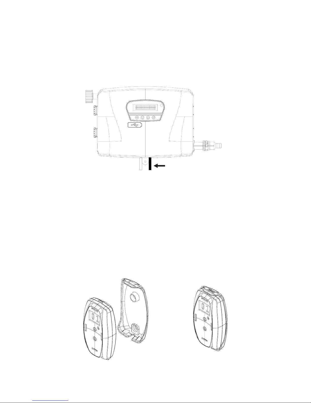
If one or more trigger wires are not used, they do not need to be connected but should be suitably isolated and
secured.
Page 10
Page 10
Hydro Systems Europe 2018
5.6.1.
Connect black power cable to power supply, ensuring correct polarity is followed; Brown is live and Blue is neutral.
5.6.2.
It is a legal requirement to allow disconnection of the appliance from the supply after installation. The disconnection
may be achieved by having the plug accessible or by incorporating a switch in the fixed wiring in accordance with the
wiring rules.
5.7.1.
The remote select is typically located on the front of the laundry machine. This allows the machine operator to change
the formula as required. Once the formula has been selected the wash program can then be started.
5.7.2
If purchased with the EvoClean, the remote formula select is installed using the flat flexible white cable already
connected to the EvoClean.
5.7.3.
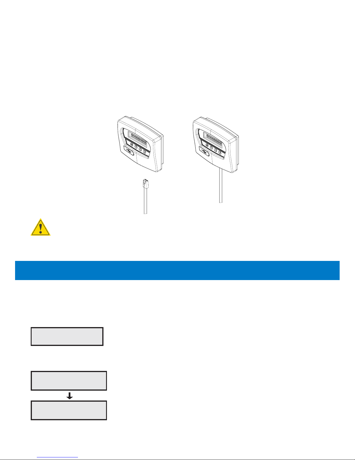
There is a handy wall bracket that allows the remote select to be mounted and removed as necessary. The wall bracket
can be installed using the double sided tape provided (front of machine) or using screws (wall), not supplied.
5.6. Installation Step 6: Power
5.7. Installation Step 7: Remote Select (optional)
Page 11
Page 11
Hydro Systems Europe 2018
5.8.1.
The off board controller is typically located on the front of the laundry machine. This allows the machine operator to
change the formula as required. Once the formula has been selected the wash program can then be started. The
additional benefit is that where the main unit may be difficult to access, all user/installer features (Inc. USB, reports...
etc) are easily accessible from the front of the machine.
5.8.2.
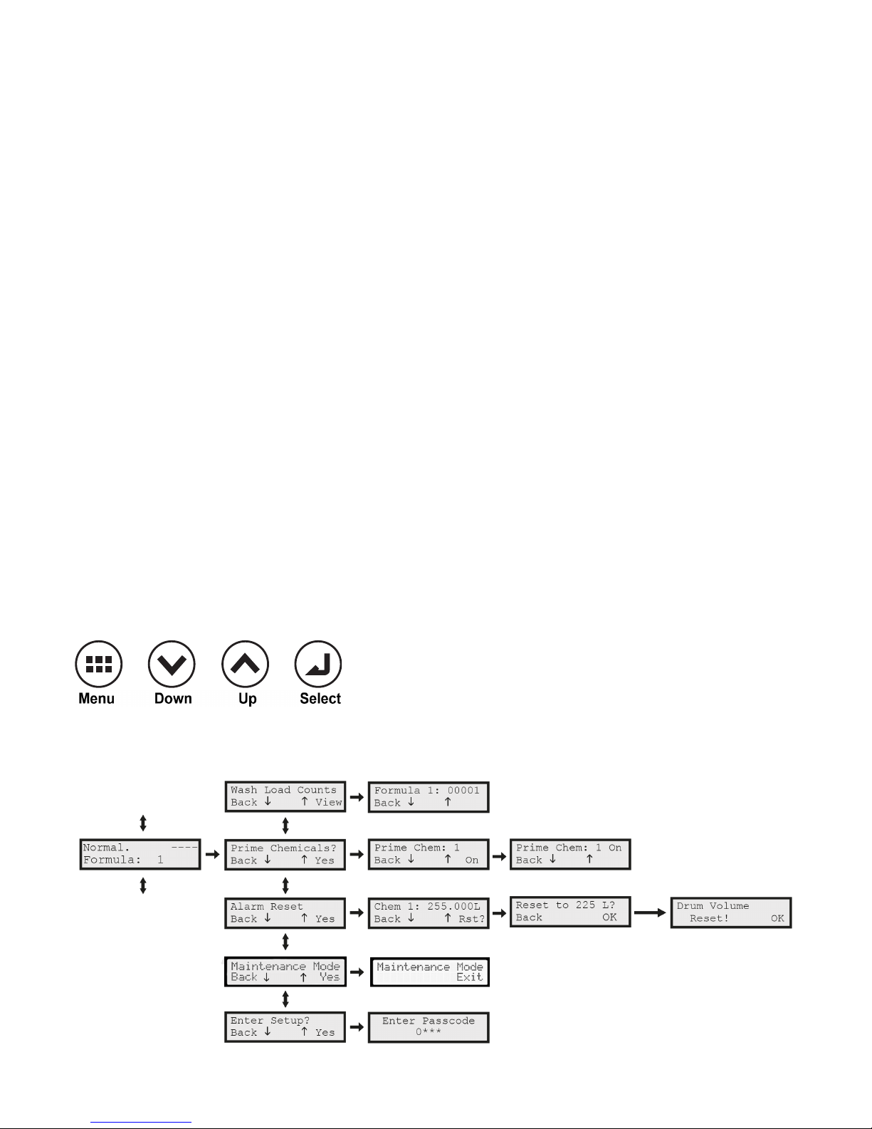
If purchased with the EvoClean, the off board controller is installed using the flat flexible grey cable already connected
to the EvoClean.
5.8.3.
The off board controller is then installed using industrial quality hook and loop tape to the front of the washing machine.
5.8. Installation Step 8: Off board controller (optional)
CAUTION
Wires left hanging loose may be a tripping hazard. Ensure all cables are secure. Be sure the tubing will be out of
the way of walkways and will not impede motion required in the area. Creating a low place in the run of tubing will
minimize drainage from the tubing.
6. setup & programming
On 1st power up the unit will prompt the installer to input the date and time. For subsequent power up’s this screen will not be
shown.
The date & time is formatted as:
Once set the unit will then prompt the installer to set one of the six languages (English, French, German, Italian, Spanish or
Japanese) that are preprogrammed into the EvoClean.
YYYY-MM-DD HH:MM
2016-10-19 11:45
Select Language?
Back i h Yes
ENGLISH
Back i h Set
6.1. Modes of Operation
Page 12
Page 12
Hydro Systems Europe 2018
6.1.1.
Normal mode allows the installer to select any of the solenoids to operate once a validated trigger signal is received (as
detailed in 5.5.1). Depending upon which input signal is received will determine which amount is used. For example a
signal on trigger 1 will inject the ‘prewash’ amount for any chemical selected to run. This allows for different volumes
of chemical to be injected at different points in the cycle. Once all the chemicals have been injected the flush solenoid
will open for the time set so that no chemical is left in the delivery hose.
Normal Mode allows the user to easily select a formula from a list of formulas by navigating to it using the up/down
arrows. Once the formula is shown the washer extractor can then be started and the particular formula is run. Each
formula has the option of being named (up to 10 characters).
The unit will accept a signal in order to change the formula automatically. This is referred to as AFS and is detailed in
5.5.3.
6.1.2.
In Relay mode the trigger signals (as detailed in 5.5.1) are directly linked to the operation of a particular solenoid
(chemical). Once a signal is received the solenoid will operate for the length of time that the signal is present. When a
signal is received the corresponding solenoid will operate, if during this time another signal is received then once the
1st solenoid closes the next one will run. If two signals are received at the same time, the lowest numbered solenoid
will operate 1st followed by the next lowest, for the length of time the signal is/was present. The flush will operate after
the solenoid closes for the length of time set or until another signal is received.
Go to Enter setup > Operational mode and select Relay Mode. The only other setup required is for the flush duration.
This can be programmed by going to Enter setup > Edit Settings > Flush Settings where the flush duration can be set
manually in seconds or by using the ‘learn’ feature where the flush is started/stopped by the push of a button.
Note: When operating the unit in relay mode a maximum of 8 products can be used (see 5.5.1).
6.2. Menu Structure
6.2.1.
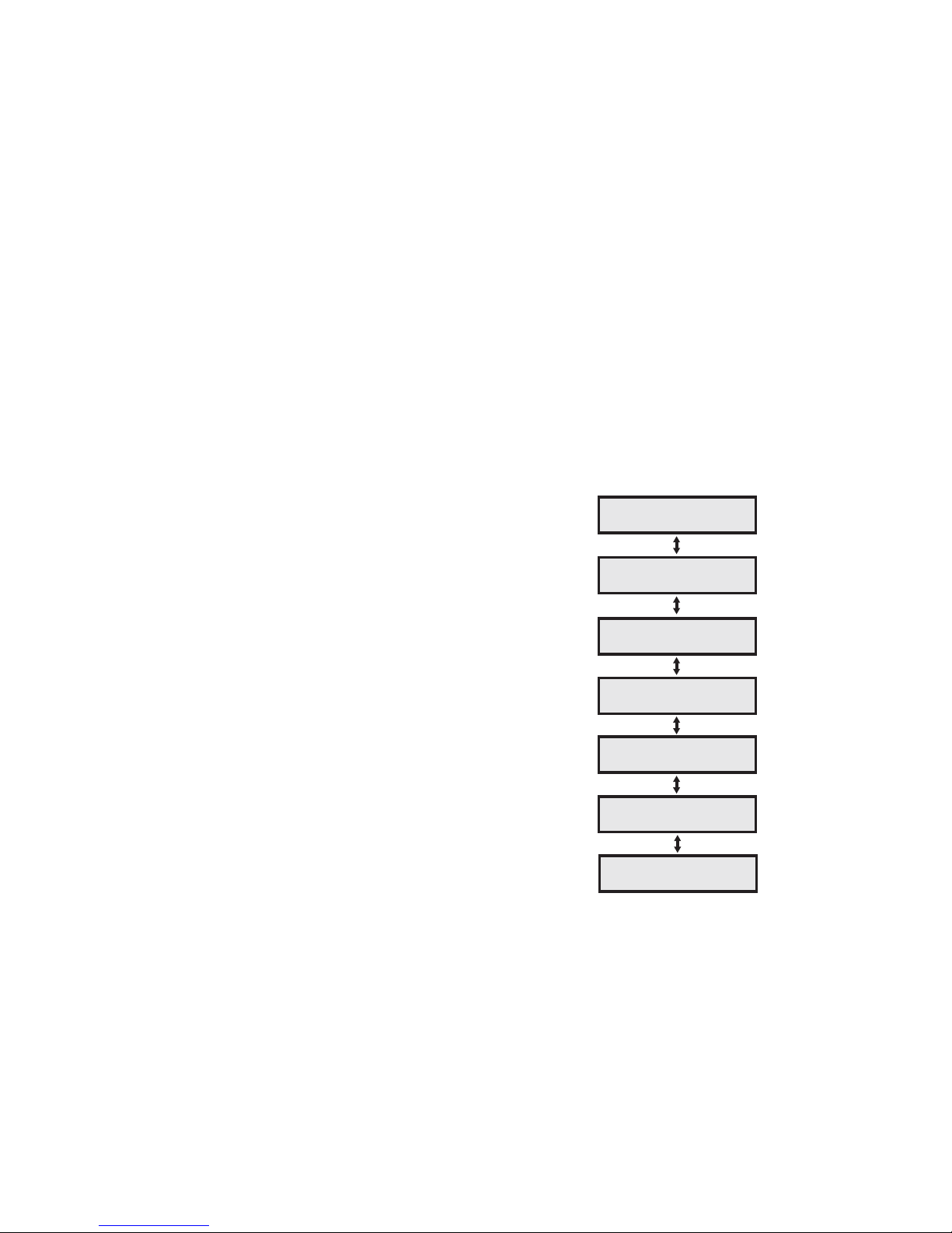
The EvoClean programming menu structure is laid out as shown at the end of this section. The following sub-sections
detail individual programming procedures.
6.2.2.
It is advisable to refer to the menu structure at the end of this section when navigating through screens, until you are
familiar with the sequence.
6.3. Unit Controls
6.4. User Screens
Page 13
Page 13
Hydro Systems Europe 2018
6.4.1.
In normal mode the unit will show the home screen detailing which formula has been selected. If the user has navigated
to any other part of the menu then after 5 minutes the unit will revert back to the home screen. Once a particular
formula has finished the unit will then revert back to Formula 1 (see alternative options in 6.5.7.2).
6.4.2.
In relay mode the home screen will just say ‘RELAY’ and only show the functionality that has been enabled in the ‘Edit
settings’ screen.
Note: It is advisable to refer to the menu structure as detailed on pages 20 & 21.
6.4.3. Maintenance mode
(Firmware version V2.09 onwards): The EvoClean now includes a ‘maintenance mode’ that can be navigated to from
the home screen (as per above).
When maintenance mode is activated the LED on the unit and RFS will flash and ‘maintenance mode’ will be displayed
on screen. When activated the unit will not accept any trigger signals, it will also not operate any solenoids or any other
functions. Maintenance mode will remain active until deactivated by the user.
Note: When in maintenance mode the unit remains powered throughout. No covers should be removed. Unit must be electrically
isolated before covers are removed.
To begin setting up the EvoClean the installer needs to
navigate to:
Enter setup > Enter passcode (Default = 1234) and the
following screens will then be accessible.
The interface has been designed to allow simple and intuitive
programming. It is recommended that the unit is setup in the
following order.
User Screens?
Back i h Yes
Machine Size
Back i h Set
Operational Mode
Back i h Set
Edit Products?
Back i h Yes
Edit Formulas?
Back i h Yes
Edit Settings?
Back i h Yes
Set Date/Time?
Back i h Yes
6.5. Setup & Programming Step 1: Program Controller
6.5.1.
User Screens - Under user screens, the installer has the functionality to prime the individual chemicals during setup
and also view and reset the wash counts per formula.
6.5.2.
Machine Size – This is set to the size of the washer extractor being installed. This can be set from 1 – 200kg. All
chemical delivery settings refer to this figure when calculating the amount of chemical to be injected during a formula.
6.5.3.
Operational Mode – As detailed in section 6.1.
Page 14

Page 14
Hydro Systems Europe 2018
6.5.5. Intermediate Flush
(Firmware version V2.09 onwards): Additional functionality has been added to the delay function of the EvoClean. An
intermediate flush option has been added so that if the delay time is set at between 40 – 999 seconds the unit will
deliver a flush cycle between chemicals. The sequence of operations will be (40-999 seconds):
i. The preceding chemical will run.
ii. The unit will then flush for the length of time set with in ‘edit settings’ (or the length of delay time if the flush
time is longer than the delay time set).
iii. The remainder of the delay time will elapse.
iv. The next chemical will run.
6.5.4. Edit Products
This is where the chemical specific settings are inputted. The chemicals are numbered from 1 upwards and each one
includes the following settings:
a) Prewash amount.
b) Main-wash amount.
c) Final rinse amount.
The chemical amounts are inputted in mls/kg and the controller calculates the chemical to be injected in conjunction
with the machine size in kgs. Special mls/kg amounts can be set within formulas to allow the user extra functionality.
d) Delay time - Although the chemical will be diluted with water anywhere from 2.5:1 up to 4:1 depending on the
application, there may be situations where the installer requires a delay time to be added between when the trigger
signal is received and the operation of the valve. This can be set from 1 to 999 seconds.
e) Chemical cost – This can be set from 0.01 to 9.99. Inputting a figure here will allow the unit to calculate the cost of
chemical usage and output the results as a report. This figure is without units so that multiple currencies can be used.
f) Drum size – When set, this will allow the unit to calculate the amount of chemical left within the drum. When 5% of
the volume is left the unit will alarm to tell the user that the chemical is running low.
g) Custom name - The chemical can be given a custom name (up to 10 characters).
h) Calibration - See section 6.7.
6.5.6. Edit Formulas
6.5.6.1 Enable/Disable
This allows the user to enable or disable a particular formula. If the formula is disabled, it will not show on the screen
when the user scrolls through the formulas.
6.5.6.2
As detailed in section 5.5.1, in Normal mode a signal received on one of the 4 Input Pins will inject programmed
amounts of product.
Beginning with Prewash signal, change the ‘x’ to a ‘P’ if that numbered product is required in that formula. This will
automatically select the mls/kg amount as set within ‘edit products’.
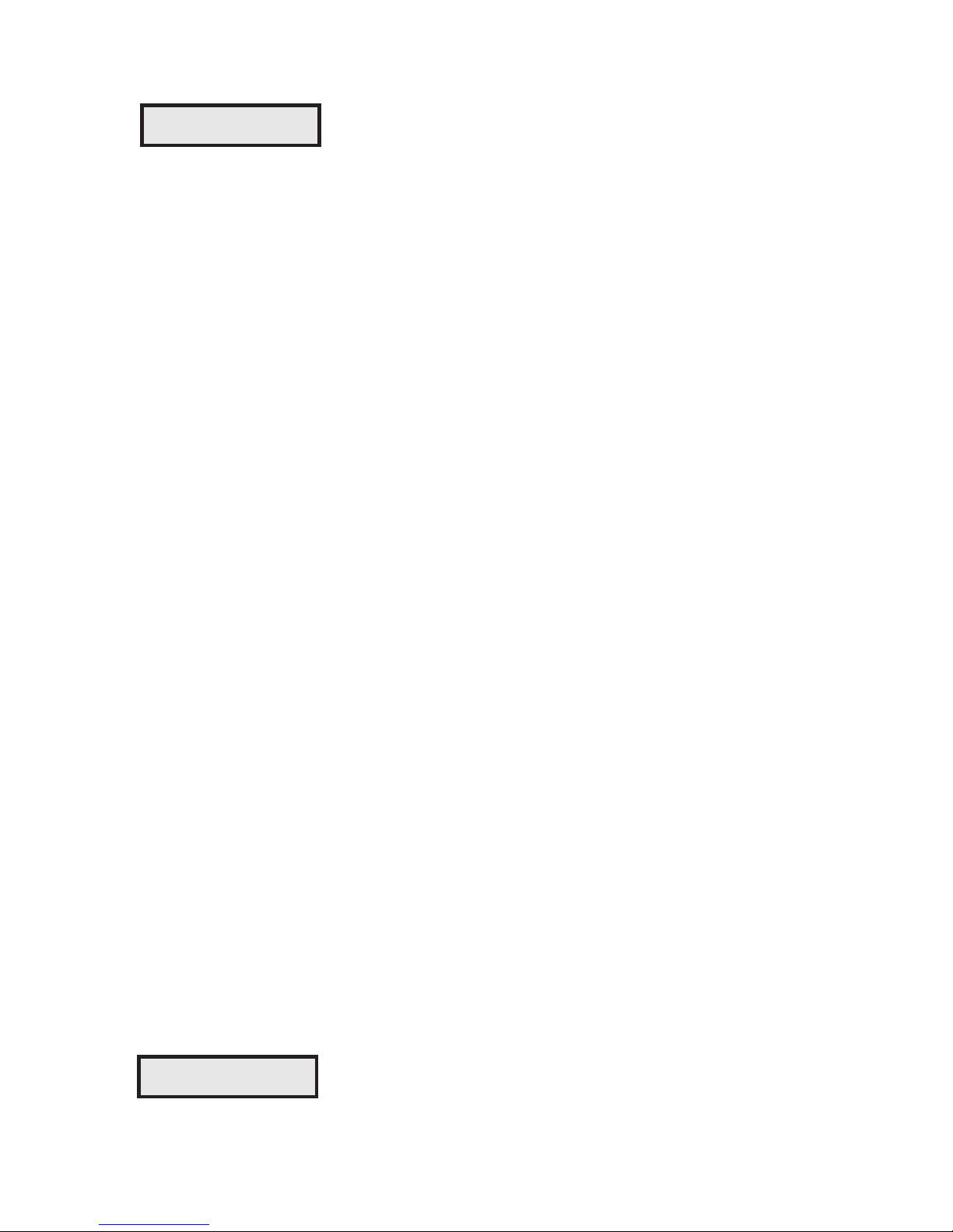
F01P Chemicals:
1P2x3x4x
F01P Chemicals:
1s2x3x4x
If a custom mls/kg amount is required within a specific formula the unit will allow this. In addition to the ‘x’ or ‘P’ you
can also select ‘s’.
When the select button is pressed in order to move to the right, if an ‘s’ has been selected an additional screen is
shown. This will allow the user to adjust the mls/kg amount.
Note: This is a display example from a 4 product unit.
Page 15
Page 15
Hydro Systems Europe 2018
F01P:C1 mls/kg:
10 i h Set
6.5.7. Edit Settings
6.5.7.1
Signal filter - This is where the signal filter time can be set. The signal is unverified until it reaches the filter time at which
point it becomes verified.
6.5.7.2
Default formula - After a wash cycle has ended the EvoClean will reset. The user can set the unit to revert to the
following states:
1. A preferred formula selected from all enabled formulas.
2. ‘Select at start’ – The unit will not accept any trigger signals until a formula is selected.
3. ‘Previous formula’ – The unit will stay on the previous formula.
Repeat the process for the Main wash, Spare and Final Rinse signal.
6.5.7.3
Allow user prime - This feature can be enabled or disabled as required. If disabled it will hide the relevant screen
preventing the user from using this feature.
6.5.7.4
Change engineers passcode - this allows the installer to change the passcode. A passcode of ‘0000‘ cannot be set
but all others are available. The default passcode is 1234.
6.5.7.5
Change user passcode – This gives the end user limited functionality to download a usage report on insertion of a
USB drive. A passcode of ‘0000’ or the engineers’ passcode cannot be set but all others are available. The default
passcode is ‘1111’.
6.5.7.6
Set lockout
On receipt of a signal on trigger 4 the unit will then reset after 5 minutes. Triggers 1-3 can be locked out for a time, as
set here, up to 99 minutes.
6.5.7.7
Product alarms - this feature can be enabled or disabled as required. If enabled it will hide the relevant screen preventing
the user from using this feature (see 5.8).
6.5.8. Flush Settings
a) Auto Start/Stop - this is an auto learn function and allows the user to press and hold a button to operate the flush.
Once released the time is automatically updated.
b) Set manually - Allows the user to manually adjust the flush time in seconds.
6.5.8.1
Firmware - This is where the firmware version can be shown. It will also show the firmware version of the remote select,
if attached.
6.5.8.2
Select language – languages available
1. English
2. French
3. Italian
4. Spanish
5. German
6. Japanese
6.5.9. Set Date/Time
This can be set here and is used to record when certain operations have taken place. The date and time is also used
during the downloading of reports.
YYY-MM-DD HH:MM
2016-10-19 11:45
Page 16
Page 16
Hydro Systems Europe 2018
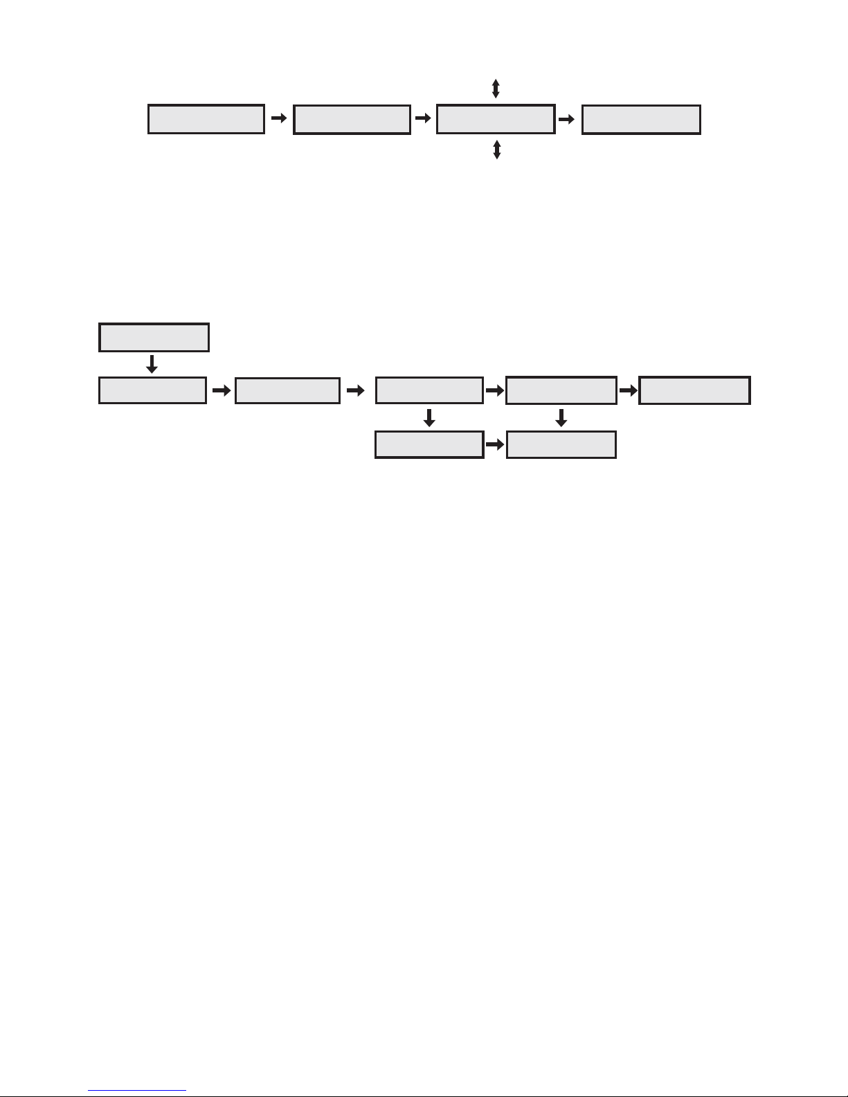
6.6. Setup & Programming Step 2: Priming
6.6.1.
Once the unit is sited, the pickup tubes are installed, the unit is now ready to be primed.
6.6.2.
Once you have navigated to the ‘Prime Chem: X’ screen the ‘select’ button is pressed (and held) whilst the chemical is
drawn up the pickup tube. To finish, release the button.
6.7. Setup & Programming Step 3: Calibration
6.7.1.
To enable the EvoClean to accurately inject the correct amount of chemical it requires calibrating. This is carried out for
all chemicals being set up.
6.7.2.
The unit is calibrated by the time taken to draw a minimum of 200ml of chemical. Once the chemical has been drawn
the user then inputs the exact amount in ml.
6.7.3.
The chemical must be fully primed for the calibration to be valid.
Normal. ----
Formula: 1
Prime Chemicals?
Back i h Yes
Prime Chem: 1
Back i h On
Prime Chem: 1 On
Back i h
C1 Calibration?
Back i h Yes
C1 Calibration?
Back Start
Keep button held
2.4 seconds
Calibration time
was: 4.95 Sec
Now enter volume
250ml i h OK
Calibration time
too short! OK
Min. 5.00 Sec.
Please retry OK
Product
Calibrated! OK
6.7.4.
Once you have navigated to the calibration screen it is then a case of pressing (and holding down) the ‘select’ button
to activate the relevant solenoid. Once the chemical has been drawn the button is then released.
6.7.5.
As long as the minimum time threshold has been passed the unit will say ‘Product Calibrated’, if the calibration time was
too short then the unit will input the default minimum and the installer will have to recalibrate.
6.8. Alarm Function
Depletion:
6.8.1.
Alarms are triggered when the estimated remaining liquid is less than 5% of full drum.
6.8.2.
Two tone sounder and flashing LED indicate an Alarm condition. Sounder is silenced as soon as any key is pressed,
the LED keeps flashing until the ‘Alarm Reset’ function is used to reset drum liquid back to its default full value. If LED
still remains flashing there will be another chemical that is also low.
6.8.3.
Setting the drum size for a particular chemical to zero will mean it is not monitored so will not trigger an alarm or show
estimate of remaining volume.
6.8.4.
Changing the drum size through the settings menu will always reset the volume estimate for that chemical back to full
drum.
6.8.5
Changing the setting of ‘Product Alarms’ in the menu to ‘Disabled’ will discard all volume estimates. Changing it to
‘Enabled’ will reset all volume estimates to full drum values.
6.8.6.
The ‘Alarm Reset’ menu shows the estimated volume remaining in the drum as well as offering the option to reset it to
full again.
Page 17
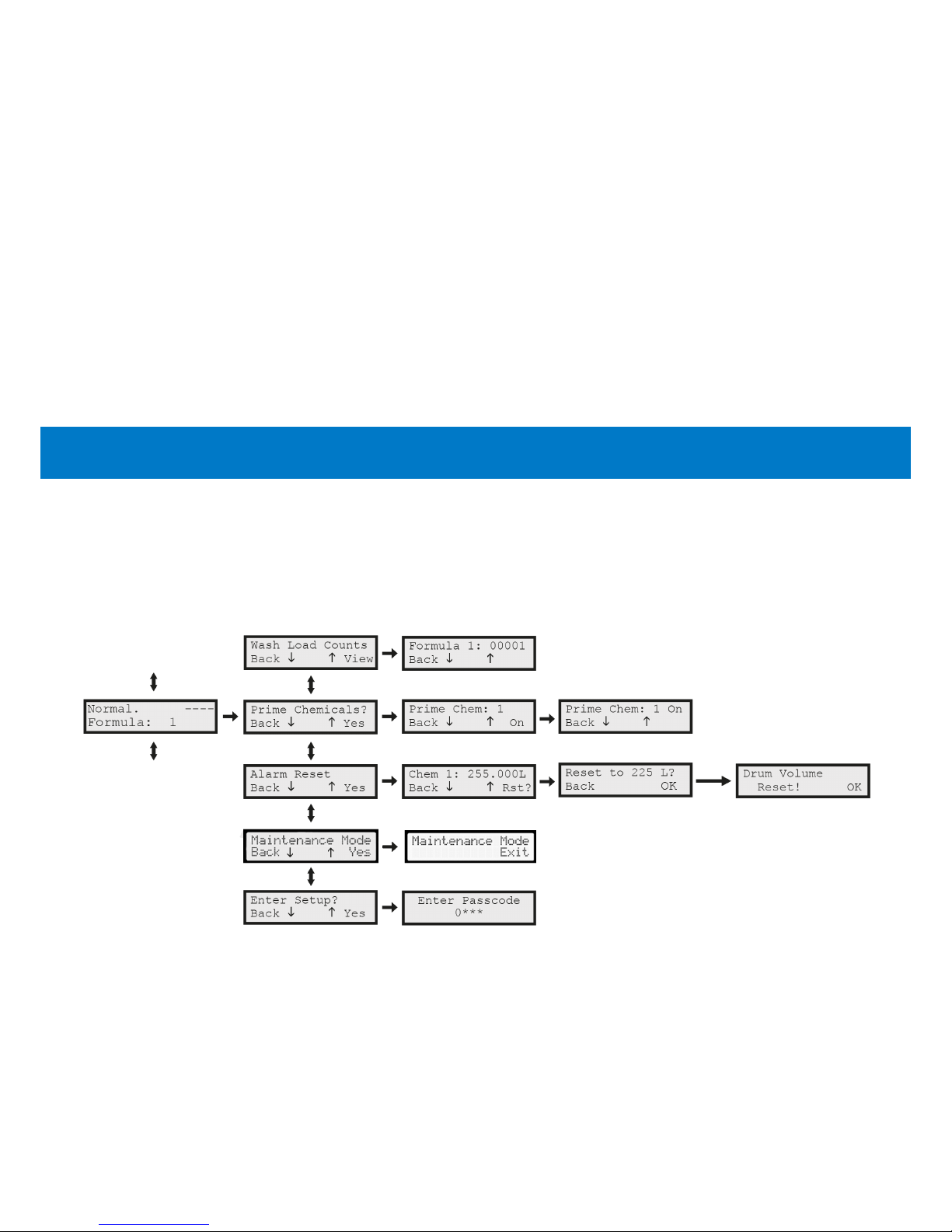
Page 17
Hydro Systems Europe 2018
6.8.7.
Volume estimates never hit zero. If the amount used should mean none is left (or technically a negative value), its set to
0.001L. In the background if it is set to zero this means it’s not monitored (e.g. when drum size is zero).
6.8.8.
In the ‘Alarm Reset’ menu, chemicals that have caused the alarm are shown with an asterisk (*) after the volume
estimate.
Sensor:
6.8.9
The EvoClean allows the addition of an external sensor. This should be a micro-switch type in a NO (normally open)
state when sufficient chemical is present.
6.9. Formula Editor
6.9.1.
To aid programming of the unit a PC application can be downloaded from the Hydro Systems Europe website
(www.hydrosystemseurope.com)
6.9.2
This will allow the installer to produce and edit programs remotely that can then be installed on the EvoClean using a
USB storage device.
* These screens are not shown if disabled.
*
*
7. menu structure
7.1. Home Screen
Page 18
Page 18
Hydro Systems Europe 2018
Customer Passcode ( See 6.5.7.5)
Load from USB?
Back i h Yes
Save to USB?
Back i h Yes
Settings Report?
Back i h Yes
Save to le:
REPORT00.htm OK
Writing to USB
Cancel?
Search for le?
Back i h Yes
Save to le:
PROG0001.HSL OK
PROG0001.HSL
Back i h Load
Writing to USB
Cancel?
Usage Report?
Back i h Yes
Enter date from:
2016-MM-DD OK
Enter date to:
2016-MM-DD OK
Events Report?
Back i h Yes
Enter date from:
2016-MM-DD OK
Enter date to:
2016-MM-DD OK
Enter Passcode:
0***
Enter Passcode:
0***
Usage Report?
Back i h Yes
Enter date from:
2016-MM-DD OK
Enter date to:
2016-MM-DD OK
7.2. USB Insert Memory Stick
Engineers passcode (See 6.5.7.4)
Page 19
Page 19
Hydro Systems Europe 2018
7.3. Settings Screen
Page 20
Page 20
Hydro Systems Europe 2018
Enter Setup?
Back i h Yes
Enter Passcode:
0***
User Screens?
Back i h Yes
Wash Load Counts
Back i h View
Edit Settings?
Back i h Yes
Prime Chemicals?
Back i h Yes
Edit Formulas?
Back i h Yes
Formula 1
Back i h Edit
F01 En/Disable?
Back i h Set
F01: Disabled
Back i h Set
F01: Enabled
Back i h Set
F01 Final Rinse
Back i h Set
F
01
R Chemicals:
1x2x3x4
P
Chemical
Selection Set!OK
F01 Spare
Back i h Set
F
01
S Chemicals:
1x2x3
P
4x
Chemical
Selection Set!OK
F01 Main Wash
Back i h Set
F
01
M Chemicals:
1
P
2x3x4x
Chemical
Selection Set!OK
F01 Prewash
Back i h Set
F
01
P Chemicals:
1
P
2x3x4x
Chemical
Selection Set!OK
Set Date/Time?
Back i h Yes
YYYY-MM-DD HH:MM
2016-10-19 11:45
Setting Saved!
OK
See page 25
7.4 Set up screen
Page 21
Page 21
Hydro Systems Europe 2018
Page 22
Page 22
Hydro Systems Europe 2018
8. maintenance
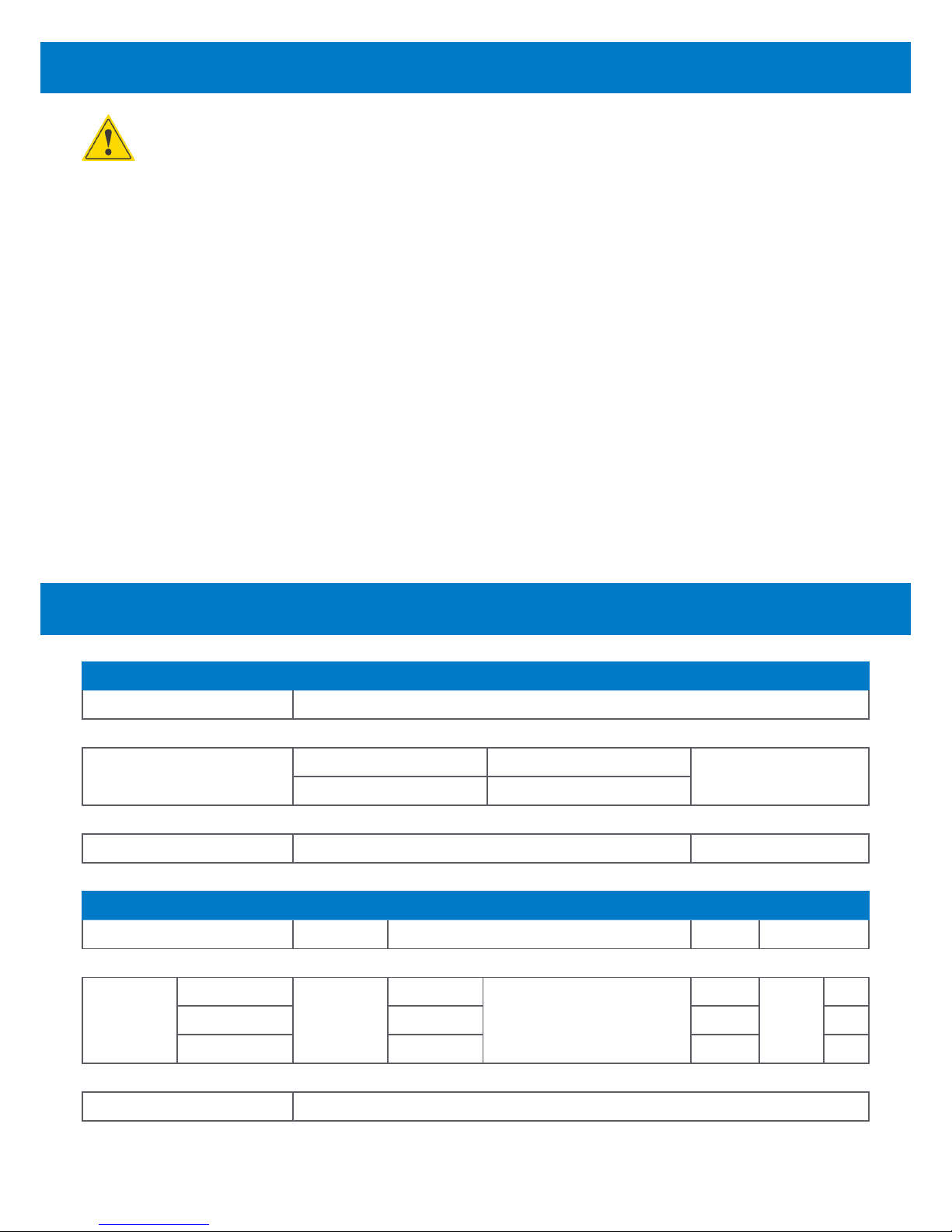
CAUTION
Before any maintenance, isolate the incoming power source and disconnect. All trigger signals should also be
isolated.
8.1.1.
If the power supply cord is damaged, it must be replaced by the manufacturer, its service agent or similarly qualified
persons in order to avoid a hazard.
8.1.2.
New hose-sets supplied with the appliance are to be used and that old hose-sets should not be reused.
8.2. Maintenance - Advised
8.2.1.
Unit frontage cleaned with a dry cloth (can be done without disconnection).
8.2.2.
Clean / Replace chemical pickup hoses.
8.2.3.
Clean / Replace inlet strainer.
8.2.4.
Clean / Replace outlet hose to machine.
8.2.5
Clean / Replace venturis as required.
8.1. Maintenance - Legal Requirements
9. specifications
UNIT
Voltage / Frequency / Current 115v-230vAC / 50-60Hz / 0.085 – 0.158A
Water Pressure (Min/Max)
Min. (Low Flow 2L/Min) 0.18 mPa (1.8 Bar / 26.1 PSI)
Max.
0.6 MPa (6 Bar / 87 PSI)
Min. (High Flow 4L/Min) 0.2 mPa (2.0 Bar / 29 PSI)
Electrical Class Class II
SYSTEM CABINET
Cabinet Material Front ASA Rear PP-TF
Size (mm)
4 Product
Height
220
Width
270
Depth
162
6 Product 220 360 162
8 Product 220 565 162
IP RATING IP22
Page 23
Page 23
Hydro Systems Europe 2018
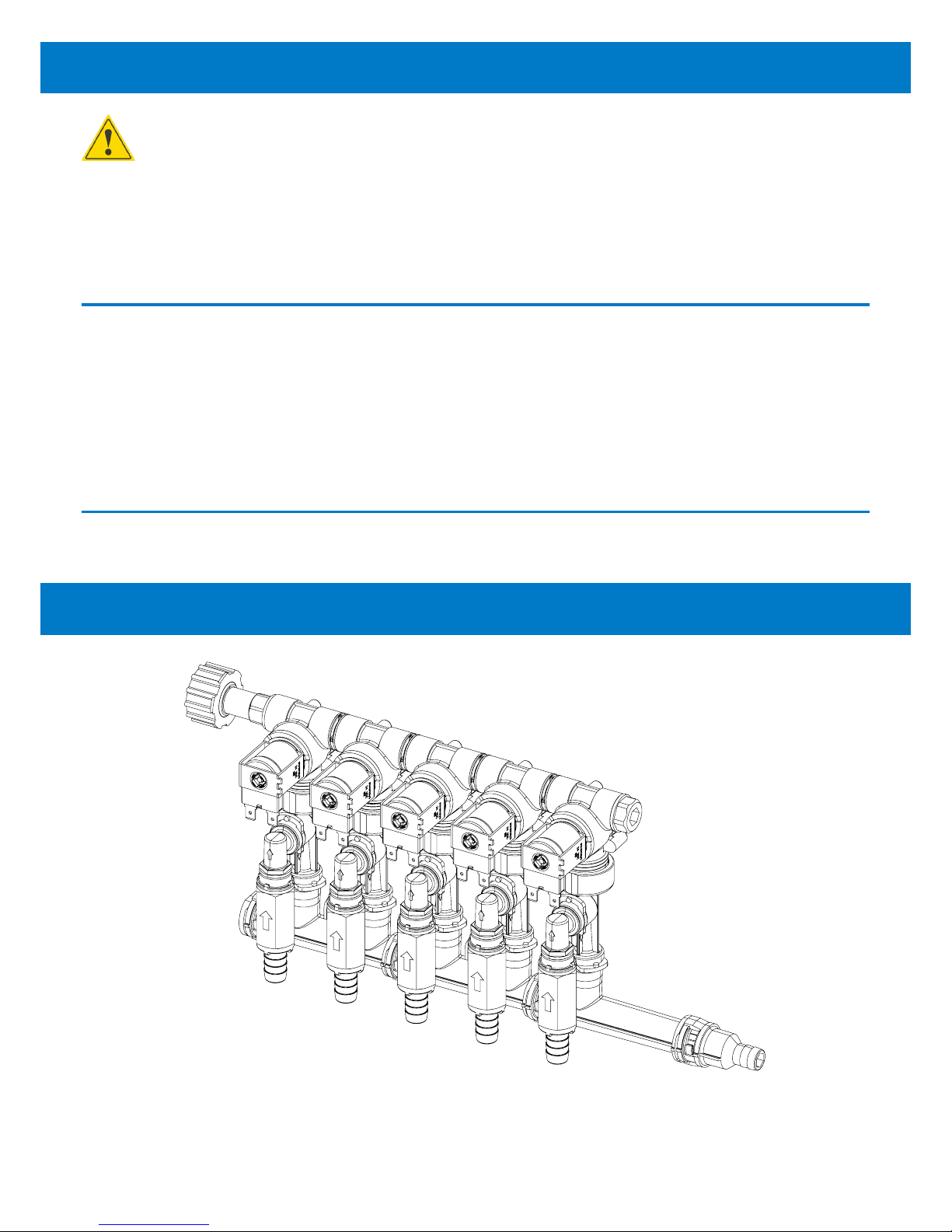
10. troubleshooting
CAUTION
Before any fault finding/troubleshooting, isolate the incoming power source and disconnect. All trigger signals
should also be isolated.
Issues listed here are to be investigated and resolved by a competent engineer.
Any fault conditions not listed within this manual should not be attempted to be fixed/replaced without the advice of Hydro
Systems Europe (Any unauthorised attempts to repair the unit will invalidate the warranty).
Issue Potential Issue Resolution
Unit will not draw chemical Low water pressure Check water line. Booster pump may be
required
Pick up tube not in chemical Ensure pick up assembly is correct.
Eductor blocked Remove & clean in warm water
Solenoid valve faulty
Blockage in chemical pickup Remove, clean and replace.
Unit will not power up No power to the unit
Faulty PCB
Check power supply
Check fuses
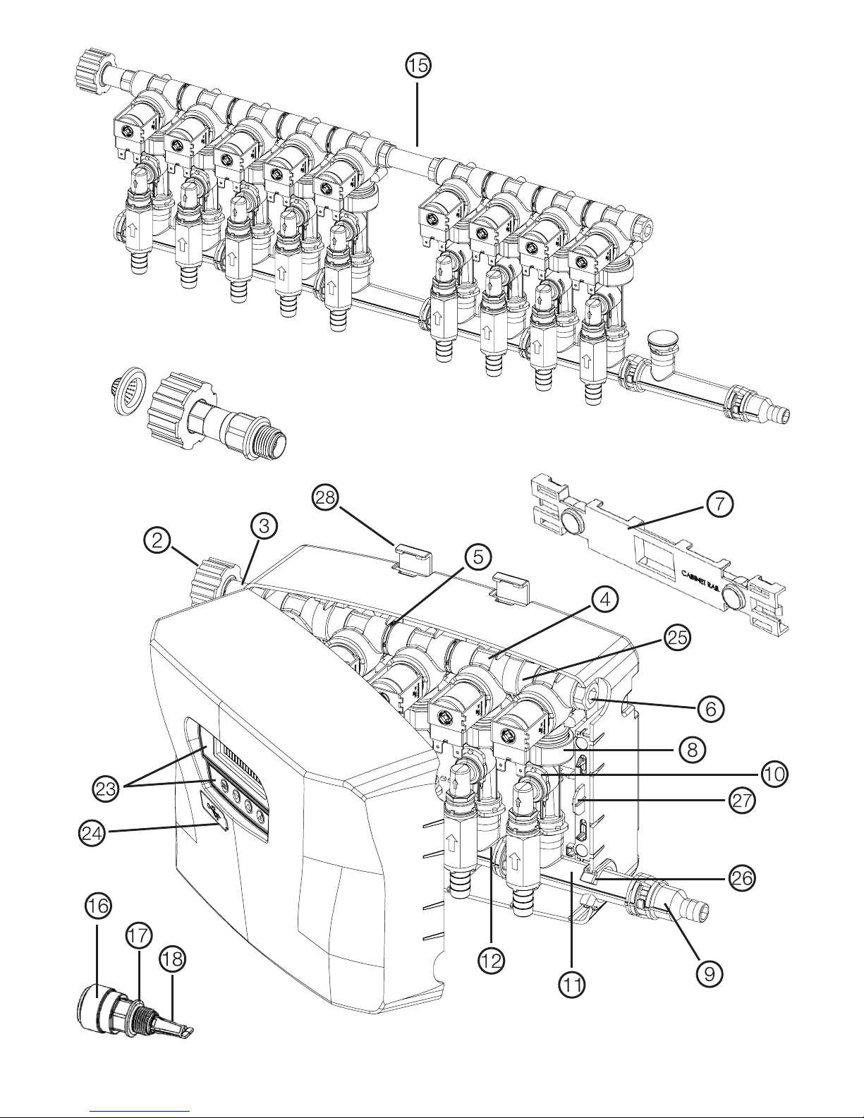
11. unit diagram & replacement parts
Page 24
Page 24
Hydro Systems Europe 2018
ref. 2 detail
Page 25

Page 25
Hydro Systems Europe 2018
11.1. Replacement Parts
Components shown on the following page should only be replaced by a competent engineer.
Any components not listed within this section should not be attempted to be replaced without the advice of Hydro Systems
Europe (Any unauthorised attempts to repair the unit will invalidate warranty).
CAUTION
Before any maintenance, isolate the incoming power source and disconnect.
ITEM # DESCRIPTION PART # NOTES
1
STRAINER WASHER 238100
INLET OPTION, 3/4“ FEMALE BSP
2
SWIVEL COLLAR 3/4“ BSP 10082835
3
SWIVEL STEM 10082801
4
WATER VALVE, 24vDC 10095315
5
VALVE NIPPLE 10075906
6
END PLUG 10075926
7
WALL BRACKET 10094361
8
EDUCTOR, 2LPM 10097802
EDUCTOR, 4LPM 10097801
9
HOSE BARB, 0.5 IN (12 MM) 90099387
HOSE BARB, 0.37 IN (10 MM) 90099388
10
EVOCLEAN CLIP, 10 PACK 10095123
11
SINGLE PORT MANIFOLD, 1-WAY TEE, PP 90099384
12
DOUBLE PORT MANIFOLD, 2-WAY TEE, PP 90099385
13
EVCL, CHK VLV, AF, 1/2 B X 1/4 FNPT, PT HS, PVC, MK2,
ASM (1)
90099463 NOT SHOWN
EVCL, CHK VLV, EP, 1/2 B X 1/4 FNPT, PT HS, PVC, MK2,
ASM (1)
90099464 NOT SHOWN
EVCL, CHK VLV, AF, 1/4NPT-F X 3/8IN BARB, MK2, ASM (1) 90099603 NOT SHOWN
EVCL, CHK VLV, AF, 1/4 FNPT X 1/4 FNPT, PT HS, PVC,
MK2, ASM (1)
90099604 NOT SHOWN
EVCL, CHK VLV,AF, 5/16 B X 1/4 FNPT, PT HS, PVC, MK2,
ASM (1)
90099605 NOT SHOWN
EVCL, CHK VLV, EP, 3/8 B X 1/4 FNPT, PT HS, PVC, MK2,
ASM (1)
90099606 NOT SHOWN
EVCL, CHK VLV, EP, 5/16 B X 1/4 FNPT, PT HS, PP, MK2,
ASM (1)
90099607 NOT SHOWN
EVCL, CHK VLV, EP, 5/16 B X 1/4 FNPT, PT HS, PVC, MK2,
ASM (1)
90099608 NOT SHOWN
14
MANIFOLD END PLUG 90099390 NOT SHOWN, PLUG
15
PIPE NIPPLE 10075904
16
15MM PUSHFIT BODY 90094370
INLET OPTION, 15MM PUSHFIT
17
PUSHFIT O-RING 10096188
18
PUSHFIT STRAINER 10094764
19
EPDM WASHER, 10 PACK 10095173 NOT SHOWN, USED IN ITEMS 8
20
EPDM O-RING, 10 PACK 10098127 NOT SHOWN, USED ON ITEMS
4,5
21
AFLAS O-RING, 10 PACK 10098128 NOT SHOWN, USED ON ITEMS
10,11,13,14, 15
22
LOCK KEY 10097834 NOT SHOWN
23
MAIN UNIT FRONT LABEL PACK 10098135
24
USB COVER 10097831
Page 26
Page 26
Hydro Systems Europe 2018
12. decommissioning & disposal
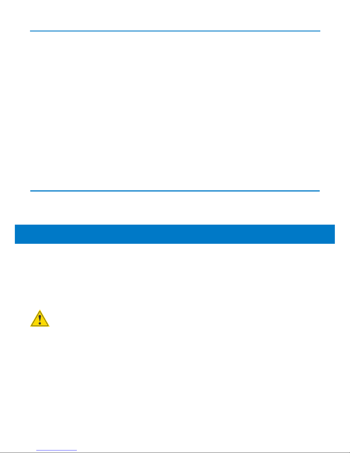
CAUTION
Before decommissioning the unit, isolate the incoming power source and disconnect. All trigger signals should also
be isolated and removed.
Hydro products are manufactured from materials which can
be recycled. Dispose of Hydro products in accordance with
the current local regulations.
• All electrical connections have been removed and disposed
of according to local regulations
• Any hazard Warning signs have been removed or totally
defaced
• Safe for disposal sign/note appended to each piece of
listed items
• The items have been left in a condition such that it is safe
for lay personnel or contractor to remove it without need
for precautions against exposure to any electrical supply
or other agents.
ITEM # DESCRIPTION PART # NOTES
A
REMOTE FORMULA SELECT 10097825
B
CHEMICAL PICKUP PVC HOSE 1.8M (6”)
11.2. Accessory Parts
ITEM # DESCRIPTION PART # NOTES
25
TOP MANIFOLD CLIP ASSEMBLY (x2) 10098136
26
MANIFOLD END SUPPORT 90099306
27
LOCK ASSEMBLY 10098138
28
UNIT TO WALL CLIPS 10098139
29
OPTIONAL NON-RETURN VALVE KIT (NRV) - 4 PRODUCT
UNIT
90099599 NOT SHOWN (STANDARD IN
APAC REGION ONLY)
30
OPTIONAL NON-RETURN VALVE KIT (NRV) - 6 PRODUCT
UNIT
90099600 NOT SHOWN (STANDARD IN
APAC REGION ONLY)
31
OPTIONAL NON-RETURN VALVE KIT (NRV) - 8 PRODUCT
UNIT
90099597 NOT SHOWN (STANDARD IN
APAC REGION ONLY)
32
KIT, TUBING, 1/2IN (12MM) X 15M, BRD PVC, (1) HYD90099609 NOT SHOWN
KIT, FOOTVALVE, FKM, W/SCREEN, ASM, BLU (4) HYD90099610 NOT SHOWN
KIT, FOOTVALVE, FKM, W/SCREEN, ASM, BLU (6) HYD90099611 NOT SHOWN
KIT, FOOTVALVE, FKM, W/SCREEN, ASM, BLU (8) HYD90099612 NOT SHOWN
KIT, FOOTVALVE, EP, W/SCREEN, ASM, GRY (4) HYD90099613 NOT SHOWN
KIT, FOOTVALVE, EP, W/SCREEN, ASM, GRY (6) HYD90099614 NOT SHOWN
KIT, FOOTVALVE, EP, W/SCREEN, ASM, GRY (8) HYD90099615 NOT SHOWN
Page 27

Page 27
Hydro Systems Europe 2018
WEEE Regulations apply to companies who Manufacture & Distribute electrical or electronic equipment. (EEE)
The WEEE Regulations apply to importers, producers, retailers and users of EEE, and to businesses that treat or recover WEEE.
The Low Level Alarm unit is a product placed onto market POST 13.08.05 , therefore called ‘future WEEE’. As a producer
Hydro Systems Europe have the option to take responsibility for the EEE placed on the market. If Hydro Systems Europe
chooses to receive WEEE they must make sure that it is disposed of in an environmentally sound way, including the treatment,
reuse, recovery and recycling of the components where appropriate.
Responsibility as a producer of EEE
Hydro Systems Europe, as a producer of EEE, are registered with a producer compliance scheme who register them with the
relevant environmental regulator.
Through the regulator they become part of an approved producer compliance scheme (PCS).The PCS supply a unique and
permanent producer registration number.
If disposal is outsourced it (the product) must be taken to an appropriately licensed site (approved authorised treatment facility
- AATF) where it can be treated safely.
Seller warrants solely to Buyer the Products will be free from defects in material and workmanship under normal use and
service for a period of one year from the date of completion of manufacture. This limited warranty does not apply to (a) hoses;
(b) and products that have a normal life shorter than one year; or (c) failure in performance or damage caused by chemicals,
abrasive materials, corrosion, lightning, improper voltage supply, physical abuse, mishandling or misapplication. In the event the
Products are altered or repaired by Buyer without Seller’s prior written approval, all warranties will be void.
No other warranty, oral, express or implied, including any warranty of merchantability or fitness for any particular purpose, is
made for these products, and all other warranties are hereby expressly excluded.
Seller’s sole obligation under this warranty will be, at Seller’s option, to repair or replace F.O.B. Seller’s facility in Cincinnati, Ohio
or Bracknell, England any Products found to be other than as warranted.
Limitation of Liability
Seller’s warranty obligations and Buyer’s remedies are solely and exclusively as stated herein. Seller shall have no other liability,
direct or indirect, of any kind, including liability for special, incidental, or consequential damages or for any other claims for
damage or loss resulting from any cause whatsoever, whether based on negligence, strict liability, breach of contract or breach
of warranty.
13. warranty
14. WEEE regulations
Page 28

Hydro Systems Europe Ltd.
Unit 3 The Sterling Centre,
Eastern Road,
Bracknell,
Berkshire, RG12 2PW
Phone+44 (O)1344 48888O
Fax+44 (O)1344 488879
Web hydrosystemseurope.com
HYD90099594 Evoclean 2
REV 12 (A) 01/2019
15. electrical approvals
Compliance to standards and test data / EC declaration of conformity
This Low Level Alarm complies with the following EU directives;
BS EN 60335-1:2012+A11:2014 Household and similar electrical appliances. Safety. General Requirements.
BS EN ISO 12100:2010 Safety of machinery. General principles for design. Risk assessment and risk
reduction.
BS EN 61000-6-1: 2007 Electromagnetic compatibility (EMC). Generic standards. Immunity for residential,
commercial and light-industrial environments.
BS EN 61000-6-3 : 2007+A1:2011 Electromagnetic compatibility (EMC). Generic standards. Emission standard for
residential, commercial and light-industrial environments.
2014/35/EU Conforms with the safety objectives of the low voltage directive and its amending directives.
2004/108/EC Conforms with the essential requirements of the electromagnetic compatibility directive and
its amending directives.
Has been designed and manufactured to the following specifications:
 Loading...