

Page 1
TPS3 SERIES YOKE MOUNT
Installation should be performed by a qualified
INSTALLATION INSTRUCTIONS
!
p
ATTENTION: DISCONNECT POWER BEFORE SERVICING
WARNING - TO REDUCE RISK OF FIRE, USE APPROPRIATE LAMP
Lamp information is found inside luminaire. Removing the reflector may be necessary to view lamp information.
SUITABLE FOR WET LOCATION
MINIMUM 90°C SUPPLY CONDUCTORS
LES FILS D’ALIMENTATION DOIVENT CONVENIR POUR 90°C
1. Please refer to ABL General Warnings Form no. 503.204 and 503.203.
2. Be sure the power is off at the supply source.
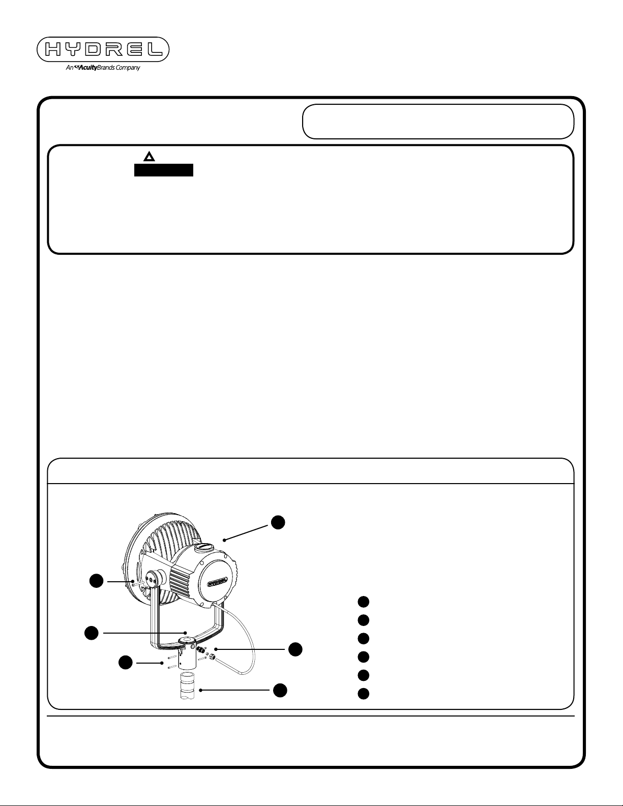
3. Ensure customer supplied 2-7/8” OD tenon (B) is properly installed and is capable of supporting fixture weight
and windload.
4. Mount fixture (A) by sliding down over 2-7/8” OD tenon (B) and securing in place using the (4) four SS 3/8-16
fasteners (C). Tenon angle should not exceed 45° from vertical.
electrician in accordance with the National Electrical Code
and relevant local codes.
5. Route fixture cord through cord seal (D) and attach to backside of fixture yoke (A). Tighten cord seal (D) outer
nut. Remove fixture yoke splice cover (E) and make all wiring connections to the fixture within the splice
compartment. Note: Make sure that there is enough cord left free for aiming of the fixture.
6. Loosen (2) fasteners (F) on Yoke Locks and aim the fixture as required. Re-tighten the (2) screws (F)
securely and the fixture is locked in position.
TPS3 MOUNTING ACCESSORY
A
F
TPS Series Yoke Mount Fixture
A
2-7/8” OD Tenon (by others)
B
E
D
C
B
SS 3/8-16 Fastener
C
1/2” NPT Cord Seal Fastener Assembly
D
Yoke Splice Cover
E
SS 1/2-13 Yoke Fasteners
F
©2014 Acuity Brands Lighting, Inc.
3/13/14
INS-TPS3
NOTE: HYDREL RESERVES THE RIGHT TO MODIFY SPECIFICATION
WITHOUT NOTICE. Any dimension on this sheet is to be assumed as a
reference dimension: “Used for information purposes only. It does not
govern manufacturing or inspection requirements.” (ANSI Y14.5-1973)
20660 Nordhoff St., Suite B
Chatsworth, CA 91311
Phone: 866.533.9901
Fax: 866.533.5291
www.hydrel.com
Page 2
TPS3 SERIES YOKE MOUNT
TENON MOUNT PLATE
Installation should be performed by a qualified
INSTALLATION INSTRUCTIONS
!
p
ATTENTION: DISCONNECT POWER BEFORE SERVICING
WARNING - TO REDUCE RISK OF FIRE, USE APPROPRIATE LAMP
Lamp information is found inside luminaire. Removing the reflector may be necessary to view lamp information.
SUITABLE FOR WET LOCATION
MINIMUM 90°C SUPPLY CONDUCTORS
LES FILS D’ALIMENTATION DOIVENT CONVENIR POUR 90°C
1. Please refer to ABL General Warnings Form no. 503.204 and 503.203.
2. Be sure the power is off at the supply source.
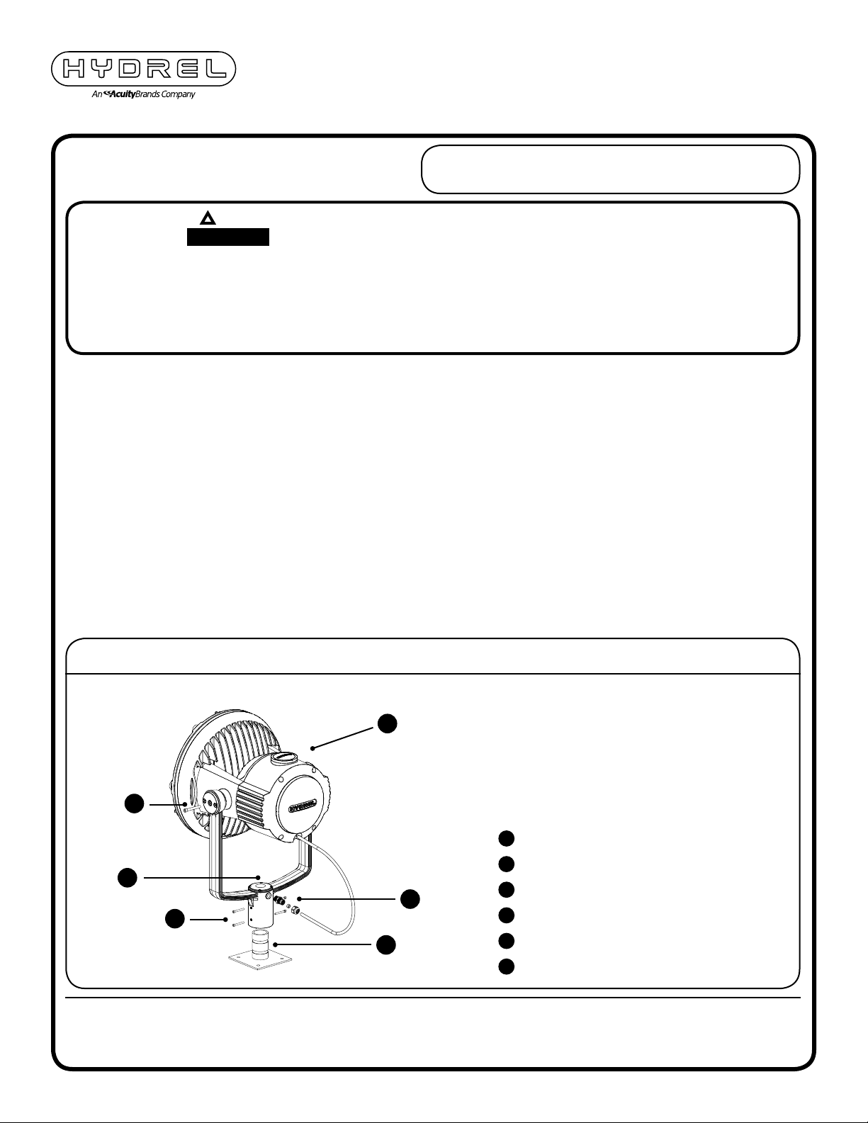
3. Ensure TNM25 Tenon Mount Plate (B) is properly installed and is capable of supporting fixture weight
and windload.
4. Mount fixture (A) by sliding down over 2-7/8” OD tenon (B) and securing in place using the (4) four SS 3/8-16
fasteners (C). Tenon angle should not exceed 45° from vertical.
electrician in accordance with the National Electrical Code
and relevant local codes.
5. Route fixture cord through cord seal (D) and attach to backside of fixture yoke (A). Tighten cord seal (D) outer
nut. Remove fixture yoke splice cover (E) and make all wiring connections to the fixture within the splice
compartment. Note: Make sure that there is enough cord left free for aiming of the fixture.
6. Loosen (2) fasteners (F) on Yoke Locks and aim the fixture as required. Re-tighten the (2) screws (F)
securely and the fixture is locked in position.
TPS3 MOUNTING ACCESSORY
A
F
TPS Series Yoke Mount Fixture
A
TNM25 Tenon Mount Plate
B
E
D
C
B
SS 3/8-16 Fastener
C
1/2” NPT Cord Seal Fastener Assembly
D
Yoke Splice Cover
E
SS 1/2-13 Yoke Fasteners
F
©2014 Acuity Brands Lighting, Inc.
3/13/14
INS-TPS3
NOTE: HYDREL RESERVES THE RIGHT TO MODIFY SPECIFICATION
WITHOUT NOTICE. Any dimension on this sheet is to be assumed as a
reference dimension: “Used for information purposes only. It does not
govern manufacturing or inspection requirements.” (ANSI Y14.5-1973)
20660 Nordhoff St., Suite B
Chatsworth, CA 91311
Phone: 866.533.9901
Fax: 866.533.5291
www.hydrel.com
Page 3
TPS3 SERIES YOKE MOUNT
PEDESTAL TENON MOUNT
Installation should be performed by a qualified
INSTALLATION INSTRUCTIONS
!
p
ATTENTION: DISCONNECT POWER BEFORE SERVICING
WARNING - TO REDUCE RISK OF FIRE, USE APPROPRIATE LAMP
Lamp information is found inside luminaire. Removing the reflector may be necessary to view lamp information.
SUITABLE FOR WET LOCATION
MINIMUM 90°C SUPPLY CONDUCTORS
LES FILS D’ALIMENTATION DOIVENT CONVENIR POUR 90°C
1. Please refer to ABL General Warnings Form no. 503.204 and 503.203.
2. Be sure the power is off at the supply source.
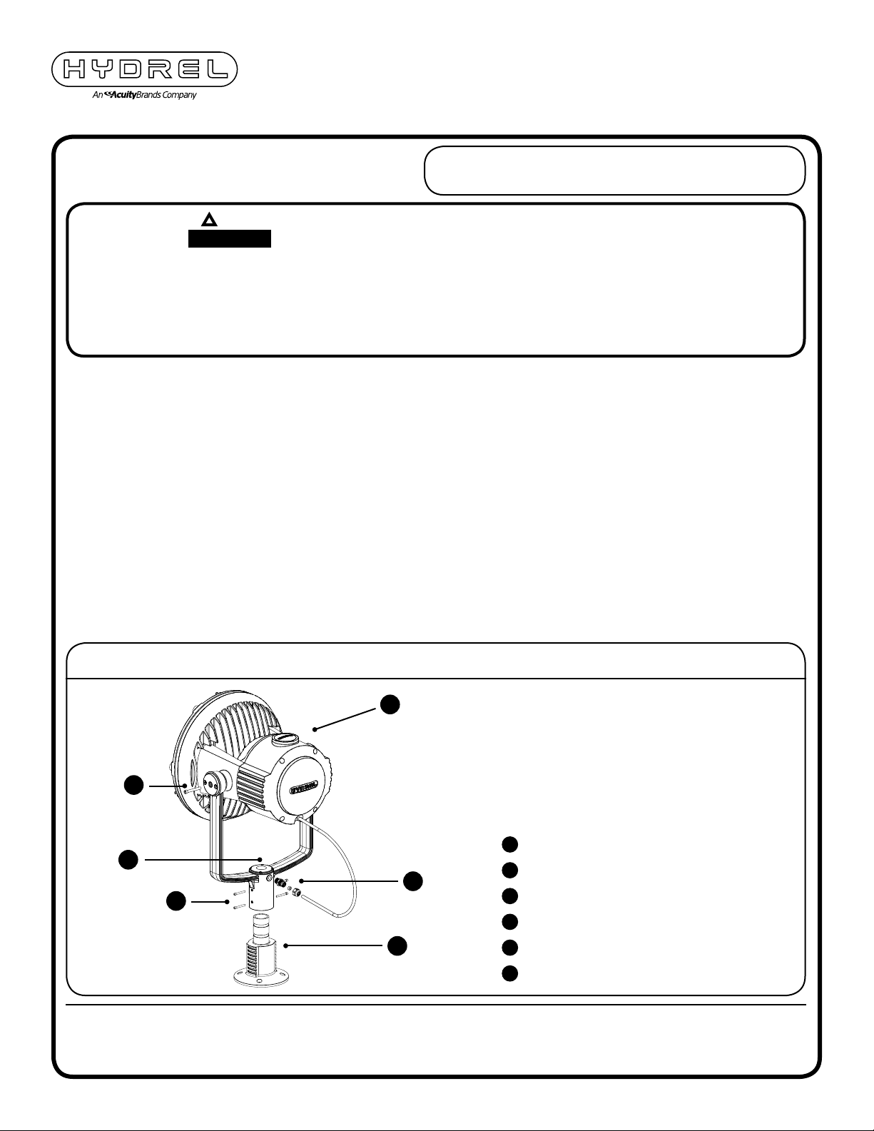
3. Ensure PED25 Pedestal Tenon Mount (B) is properly installed and is capable of supporting fixture weight
and windload.
4. Mount fixture (A) by sliding down over 2-7/8” OD tenon (B) and securing in place using the (4) four SS 3/8-16
fasteners (C). Tenon angle should not exceed 45° from vertical.
electrician in accordance with the National Electrical Code
and relevant local codes.
5. Route fixture cord through cord seal (D) and attach to backside of fixture yoke (A). Tighten cord seal (D) outer
nut. Remove fixture yoke splice cover (E) and make all wiring connections to the fixture within the splice
compartment. Note: Make sure that there is enough cord left free for aiming of the fixture.
6. Loosen (2) fasteners (F) on Yoke Locks and aim the fixture as required. Re-tighten the (2) screws (F)
securely and the fixture is locked in position.
TPS3 MOUNTING ACCESSORY
A
F
TPS Series Yoke Mount Fixture
A
E
D
C
PED25 Pedestal Tenon Mount
B
SS 3/8-16 Fastener
C
1/2” NPT Cord Seal Fastener Assembly
D
©2014 Acuity Brands Lighting, Inc.
3/13/14
INS-TPS3
B
NOTE: HYDREL RESERVES THE RIGHT TO MODIFY SPECIFICATION
WITHOUT NOTICE. Any dimension on this sheet is to be assumed as a
reference dimension: “Used for information purposes only. It does not
govern manufacturing or inspection requirements.” (ANSI Y14.5-1973)
Yoke Splice Cover
E
SS 1/2-13 Yoke Fasteners
F
20660 Nordhoff St., Suite B
Chatsworth, CA 91311
Phone: 866.533.9901
Fax: 866.533.5291
www.hydrel.com
Page 4
TPS3 SERIES YOKE MOUNT
STANCHION MOUNT
Installation should be performed by a qualified
INSTALLATION INSTRUCTIONS
!
p
ATTENTION: DISCONNECT POWER BEFORE SERVICING
WARNING - TO REDUCE RISK OF FIRE, USE APPROPRIATE LAMP
Lamp information is found inside luminaire. Removing the reflector may be necessary to view lamp information.
SUITABLE FOR WET LOCATION
MINIMUM 90°C SUPPLY CONDUCTORS
LES FILS D’ALIMENTATION DOIVENT CONVENIR POUR 90°C
1. Please refer to ABL General Warnings Form no. 503.204 and 503.203.
2. Be sure the power is off at the supply source.
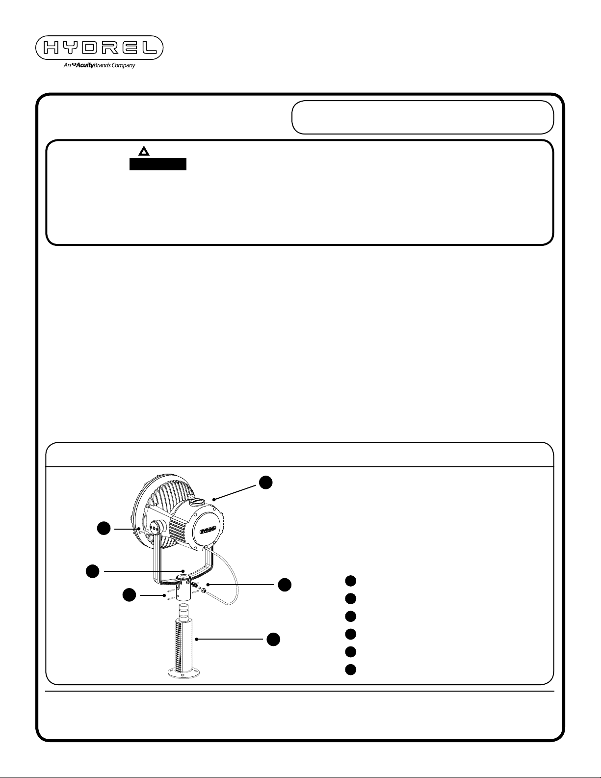
3. Ensure SM1825 Stanchion Mount (B) is properly installed and is capable of supporting fixture weight
and windload.
4. Mount fixture (A) by sliding down over 2-7/8” OD tenon (B) and securing in place using the (4) four SS 3/8-16
fasteners (C). Tenon angle should not exceed 45° from vertical.
electrician in accordance with the National Electrical Code
and relevant local codes.
5. Route fixture cord through cord seal (D) and attach to backside of fixture yoke (A). Tighten cord seal (D) outer
nut. Remove fixture yoke splice cover (E) and make all wiring connections to the fixture within the splice
compartment. Note: Make sure that there is enough cord left free for aiming of the fixture.
6. Loosen (2) fasteners (F) on Yoke Locks and aim the fixture as required. Re-tighten the (2) screws (F)
securely and the fixture is locked in position.
TPS3 MOUNTING ACCESSORY
A
F
E
D
C
B
TPS Series Yoke Mount Fixture
A
SM1825 Stanchion Mount
B
SS 3/8-16 Fastener
C
1/2” NPT Cord Seal Fastener Assembly
D
Yoke Splice Cover
E
©2014 Acuity Brands Lighting, Inc.
3/13/14
INS-TPS3
SS 1/2-13 Yoke Fasteners
F
NOTE: HYDREL RESERVES THE RIGHT TO MODIFY SPECIFICATION
WITHOUT NOTICE. Any dimension on this sheet is to be assumed as a
reference dimension: “Used for information purposes only. It does not
govern manufacturing or inspection requirements.” (ANSI Y14.5-1973)
20660 Nordhoff St., Suite B
Chatsworth, CA 91311
Phone: 866.533.9901
Fax: 866.533.5291
www.hydrel.com
Page 5
TPS3 SERIES YOKE MOUNT
WIRING
Installation should be performed by a qualified
INSTALLATION INSTRUCTIONS
!
p
ATTENTION: DISCONNECT POWER BEFORE SERVICING
WARNING - TO REDUCE RISK OF FIRE, USE APPROPRIATE LAMP
Lamp information is found inside luminaire. Removing the reflector may be necessary to view lamp information.
SUITABLE FOR WET LOCATION
MINIMUM 90°C SUPPLY CONDUCTORS
LES FILS D’ALIMENTATION DOIVENT CONVENIR POUR 90°C
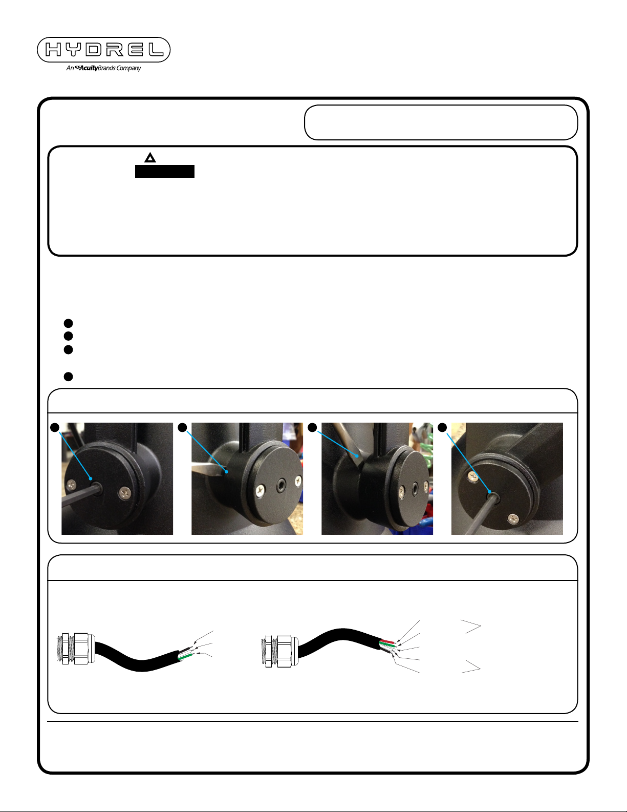
* Yoke Locks may become fully engaged in fixture head during shipment or after installation and not allow for fixture
re-aiming. This is a normal operation and may require the Yoke Locks to be dis-engaged for re-aiming.
To dis-engage Yoke Locks:
A
- Loosen Yoke Lock center fasteners on each yoke lock
B
2 - Locate Yoke Lock/Fixture interface disengagement slots. Slots are located perpendicular to yoke axis (Fig.1)
C
- Insert large flat blade screwdriver into slots and pull screwdriver handle away from fixture body releasing the
Yoke Lock.
D
- Adjust fixture and re-tighten center Yoke Lock fasteners.
electrician in accordance with the National Electrical Code
and relevant local codes.
YOKE ADJUSTMENT DIAGRAM
A
B
C D
TPS3 WIRING DIAGRAM
Standard Fixture Dimming Fixture
Black
White
Green
(+) Red
(-) Green
Bare Wire - Earth Ground
(+) White
(-) Black
Wire
Power Supply
©2014 Acuity Brands Lighting, Inc.
3/13/14
INS-TPS3
NOTE: HYDREL RESERVES THE RIGHT TO MODIFY SPECIFICATION
WITHOUT NOTICE. Any dimension on this sheet is to be assumed as a
reference dimension: “Used for information purposes only. It does not
govern manufacturing or inspection requirements.” (ANSI Y14.5-1973)
20660 Nordhoff St., Suite B
Chatsworth, CA 91311
Phone: 866.533.9901
Fax: 866.533.5291
www.hydrel.com
 Loading...