

Page 1
Titan H2O Kubota
Owner’s Manual
HydraMaster
11015 47th Avenue West
Mukilteo, Washington 98275
MAN-44359 Rev. 0, April 13, 2012
No part of this manual may be reproduced or used in any form or by any means (i.e. graphic, electronic, photocopying or electronic
retrieval systems) without the express written permission of HydraMaster. Specications and information in this document are
subject to change without prior notice.
(182-860-D)
All rights reserved. © 2012 HydraMaster
Page 2

Page 3

Table of Contents
GeNeRAl INfORMATION ...........................................................................SeCTION 1
Contact Information ................................................................................. 1-4
Warnings, Cautions and Notices ............................................................. 1-5
Responsibilities .......................................................................................1-8
Machine Specications ........................................................................... 1-11
Optional equipment.................................................................................1-12
Spare Parts .............................................................................................1-13
High Altitude Operation ...........................................................................1-13
Waste Water Disposal Advisory ..............................................................1-14
INSTAllATION INfORMATION ...................................................................SeCTION 2
Operating the Titan H2O In Hot Weather .................................................2-1
locating the Titan H2O In Vehicle ............................................................2-2
Setting Up the Titan H2O .........................................................................2-3
Orientation of fuel Pump ........................................................................ 2-4
OPeRATING INSTRUCTIONS .....................................................................SeCTION 3
Start Up Procedure ................................................................................. 3-2
Shut Down Procedure .............................................................................3-2
MACHINe MAINTeNANCe ..........................................................................SeCTION 4
Operational Maintenance ........................................................................4-2
Overall Machine Maintenance.................................................................4-3
engine Maintenance ............................................................................... 4-4
Vacuum System Maintenance ................................................................ 4-7
eleCTRICAl SySTeM ................................................................................SeCTION 5
electrical System Information..................................................................5-1
SySTeMS TROUbleSHOOTING ...............................................................SeCTION 6
engine .....................................................................................................6-1
Vacuum System ...................................................................................... 6-4
i - Titan H2O Owner’s Manual
Page 4

ASSeMblIeS AND PARTS lIST .................................................................SeCTION 7
Machine Assembly Parts list ..................................................................7-6
frame Assembly Parts list .....................................................................7-8
Top Cover Assembly Parts list ...............................................................7-9
Side Cover Assembly Parts list .............................................................. 7-10
engine Assembly Parts list..................................................................... 7-14
blower and Silencer Assembly Parts list ................................................7-16
exhaust Assembly Parts list ...................................................................7-18
flywheel Plate Assembly Parts list ........................................................7-20
Upper Dash Assembly Parts list............................................................. 7-22
lower Dash Assembly Parts list............................................................. 7-23
Grill Assembly Parts list .........................................................................7-24
electrical Panel Assembly Parts list ....................................................... 7-27
100 Gallon Universal Recovery Tank (URT) Assembly Parts list ...........7-29
100 Gallon Universal Recovery Tank (URT) Cover Assembly Parts list 7-31
Vacuum Relief Valve Assembly Parts list ...............................................7-32
HOW TO ORDeR PARTS ............................................................................SeCTION 8
Warranty Parts Orders ............................................................................8-1
Parts Orders ............................................................................................ 8-1
emergencies ...........................................................................................8-1
WARRANTy INfORMATION .......................................................................SeCTION 9
blower .....................................................................................................9-1
Vacuum Tank ........................................................................................... 9-1
Vacuum Hoses ........................................................................................9-1
Recovery Wand ......................................................................................9-1
Golden Guarantee ..................................................................................9-1
Titan H2O Owner’s Manual - ii
Page 5

list of figures
figure 1-1. Illustration Showing left and Right Views
of Titan H2O without Side and belt Covers ...............................................1-3
figure 2-1. location of Roof Vents in Vehicle .............................................................2-1
figure 2-2. Recommended location of Titan H2O in Van ............................................2-2
figure 2-3. Install fuel Pump, Outlet Side Up .............................................................2-4
figure 2-4. fuel Pump Must be in Vertical Position ....................................................2-4
figure 3-1. Titan H2O front Panel Assembly ...............................................................3-1
figure 5-1. electrical Schematic .................................................................................5-2
figure 5-2. Wiring Diagram - View 1 of 3 ...................................................................5-3
figure 5-3. Wiring Diagram - View 2 of 3 ...................................................................5-4
figure 5-4. Wiring Diagram - View 3 of 3 ...................................................................5-5
figure 7-1. Machine Assembly - View 1 of 4 ...............................................................7-2
figure 7-2. Machine Assembly - View 2 of 4 ...............................................................7-3
figure 7-3. Machine Assembly - View 3 of 4 ...............................................................7-4
figure 7-4. Machine Assembly - View 4 of 4 ...............................................................7-5
figure 7-5. frame Assembly .......................................................................................7-7
figure 7-6. Top Cover Assembly ................................................................................7-9
figure 7-7. Side Cover Assembly .............................................................................7-10
figure 7-8. engine Assembly - View 1 of 3 ................................................................ 7-11
figure 7-9. engine Assembly - View 2 of 3 ...............................................................7-12
figure 7-10. engine Assembly - View 3 of 3 .............................................................7-13
figure 7-11. blower and Silencer Assembly .............................................................7-15
figure 7-12. exhaust Assembly ................................................................................7-17
figure 7-13. flywheel Plate Assembly .....................................................................7-19
figure 7-14. Upper Dash Assembly- View 1 of 2 ......................................................7-21
figure 7-15. Upper Dash Assembly - View 2 of 2 ......................................................7-22
figure 7-16. lower Dash Assembly ..........................................................................7-23
figure 7-17. Grill Assembly ......................................................................................7-24
figure 7-18. electrical Panel Assembly - View 1 of 2 ................................................7-25
figure 7-19. electrical Panel Assembly - View 2 of 2 ................................................7-26
figure 7-20. 100 Gallon Universal Recovery Tank (URT) Assembly .........................7-28
figure 7-21. 100 Gallon Universal Recovery Tank (URT) Cover Assembly ..............7-30
figure 7-22. Vacuum Relief Valve Assembly ............................................................7-32
iii - Titan H2O Owner’s Manual
Page 6

Titan H2O Owner’s Manual - iv
Page 7
1- General Information
HydraMaster’s Titan H2O Water Recovery System has been designed to better
accommodate the needs of water extraction, recovery and restoration professionals.
The Titan H2O features a WG 972 Kubota engine that powers a Tuthill 4007 Tri-lobe
vacuum blower. This combination produces over 400 cfm of air ow, more than enough
to extract water with one or two wands
(or other extraction tools).
HydraMaster’s reliable Dura-flow
Automatic Pump Out (APO), offered as
an option, allows you to extract water
without the need to shut down and
dispose of the recovered water.
Other features of the Titan H2O include:
Dual oil bath and sight glasses for
•
enhanced blower reliability
Dual tool/wand capable
•
In addition to the obvious performance
aspects of the Titan H2O, it delivers
maximum reliability and can be
easily serviced. All service points
are conveniently located so routine
maintenance takes only a few minutes
to perform.
HydraMaster suggests that the operator
of the machine be well acquainted with
the IICRC guidelines for flood extraction and with the various methods of carpet and
surface drying that are currently being used. It is also recommended that the machine
operator be familiar with the local municipality’s requirements for the proper disposal of
waste water.
As with any machine, it is important to use the Titan H2O correctly. Operating the machine
is simple as described in Section 3 of this Owner’s Manual. This manual also contains
installation as well as information required for proper maintenance, adjustment and
repair of the Titan H2O. Component troubleshooting guides have been included for your
convenience.
1-1: General Information
Page 8

It is the purpose of this manual to help you properly understand, maintain and service
your Titan H2O. follow the directions carefully and you will be rewarded with years of
protable, trouble-free operation.
No section of this manual should be overlooked when preparing for operation of the
Titan H2O. Please read the manual to familiarize yourself with the operation of your
machine, paying special attention to all Warnings and Cautions.
This section of the manual contains the following information:
Contact Information
Warnings, Cautions and Notices
Responsibilities
Machine Specications
High Altitude Operation
Waste Water Disposal Advisory
General Information: 1-2
Page 9
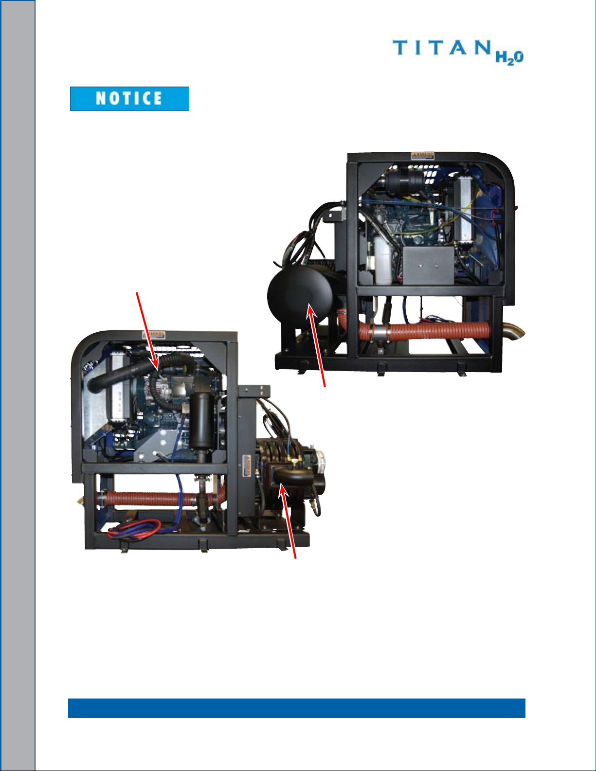
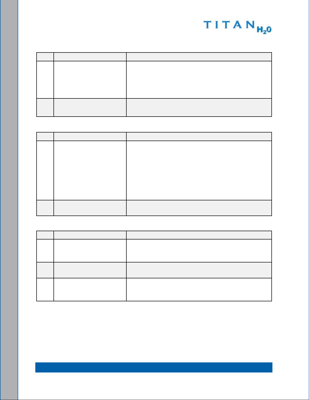
Photographs and illustrations, such as those included in this document, can
represent optional equipment as well as standard equipment.
Engine
Silencer
Vacuum Blower
Illustration Showing Left and Right Views Figure 1-1.
of Titan H2O without Side and Belt Covers
1-3: General Information
Page 10

COnTaCT InFORMaTIOn
If you have any questions regarding the operation, maintenance or repair of this machine,
please contact your local distributor.
To nd a local distributor, please visit our website at:
http://hydramaster.com/HowTobuy/Dealerlocator.aspx
If your question cannot be resolved by your distributor or by the information within this
manual, you may contact HydraMaster direct using the following phone numbers.
HOURS TELEPHOnE nUMBERS E-MaIL aDDRESSES
Monday-friday
Technical Support
(425) 775-7275
fAX : (800) 426-4225
techsupport@hydramaster.com
Technical Support
7:00 a.m. to 5:00 p.m.
Pacic Standard Time
Customer Service/Parts
(425) 775-7276
fAX: (425) 771-7156
Customer Service/Parts
parts@hydramaster.com
When calling your distributor, be sure to reference the serial number and date of
purchase.
FOR YOUR REFEREnCE:
Serial no.____________________________________________________
Date of Purchase:_____________________________________________
Purchased From (Distributor): __________________________________
General Information: 1-4
Page 11
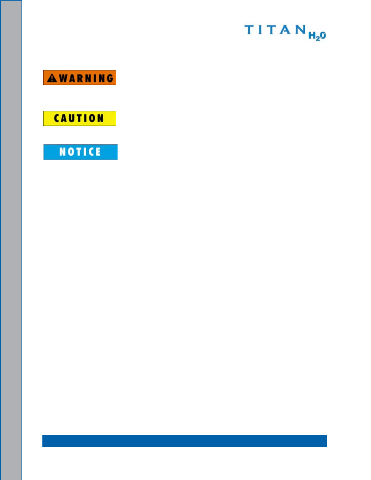
WaRnIngS, CaUTIOnS anD nOTICES
HydraMaster uses this WARNING symbol throughout the manual to warn of
possible injury or death.
This CAUTION symbol is used to warn of possible equipment damage.
This NOTICe symbol indicates that federal or state regulatory laws may apply,
and also emphasizes supplemental information.
1-5: General Information
Page 12

Warnings and Cautions specic to the Titan H
O include the following:
2
During the operation of the truckmount many components are in motion. Never
touch any part of the truckmount that is in motion. Serious injury may result.
During the operation of the truckmount many surfaces will become extremely hot.
Never touch hot surfaces. Serious injury may result.
The operation of this truckmount can produce noise levels exceeding 85 decibels
to a distance of 10 ft (3.05 m). The Occupational Safety and Health Administration
(OSHA) recommends the use of hearing protective equipment if a person is
exposed to an average of 85 decibels over an 8-hour period. Check with local
and state agencies concerning hearing conservation rules.
During the operation of the truckmount carbon monoxide and other toxic fumes
are produced. Position the vehicle so that any fumes produced will be directed
away from inhabited areas and any points of building entry (doors, windows, air
conditioning units, fans, etc.). Do not occupy the vehicle while the truckmount is
in operation. Serious injury may result.
During the operation of the truckmount, chemicals known to the State of California
to cause cancer, birth defects and other reproductive harm are produced by the
engine exhaust.
Never operate the truckmount with a portable gas container inside the vehicle.
Doing so will increase the risk of re and explosion. Serious injury or death may
result.
Transporting a vented fuel container that presently contains, or has ever contained
in the past, a ammable liquid is strictly forbidden by HydraMaster and by federal
and state regulations. Doing so will increase the risk of re and explosion. Serious
injury or death may result.
General Information: 1-6
Page 13
Never smoke in or around the truckmount. Doing so will increase the risk of re
and explosion. Serious injury or death may result.
During the operation of the truckmount the exhaust system will become extremely
hot. Keep all ammable materials away from the truckmount exhaust system.
Failure to do so will increase the risk of re and explosion. Serious property
damage may result.
Never operate the truckmount when the vehicle is tilted more than 10 degrees in
any direction. Doing so will result in improper lubrication of the internal components,
and will increase the risk of serious component or engine damage.
Never operate the truckmount with the vehicle doors closed. Doing so results in
extremely high temperatures inside the vehicle and will lead to serious component
or engine damage.
Many vehicles have critical components mounted directly below the oor that
can easily be damaged. Before drilling holes in the oor of the vehicle inspect
the underside of the vehicle for critical components. failure to do so may result
in damage to the vehicle.
1-7: General Information
Page 14
Responsibilities
purchaser’s Responsibilities
Prior to purchasing a van, ensure that the payload is suitable for all of the equipment •
that will be installed and transported. This includes and is not limited to: the truckmount,
recovery tanks, hose reels, hoses, tools and drying equipment. Payload capacity
information is available through the auto dealer, the manufacturer’s web site, and is
also located on the door pillar of the driver’s side door.
Purchase a heavy duty Group 24 (500+ CC Amps) battery for this truckmount. This is •
normally available from the installation dealer.
Prior to dropping your van off at the distributor for the truckmount to be installed, have •
aspray-onbedlinerappliedtotheoorsuchasRhinoLining®orLine-X®.
Plywood and carpet are not recommended.
Prior to operating the truckmount, read this manual in its entirety and familiarize •
yourself with the information contained here. Special attention should be paid to all
Warnings and Cautions.
The distributor is responsible for the correct installation of the truckmount. The •
distributor is also responsible to train you in the correct and proper operation and
maintenance of the truckmount.
Anymodicationofthetruckmountmayvoidthewarranty.
General Information: 1-8
Page 15

Distributor’s Responsibility
Acceptance of Shipment
before accepting the truckmount, check the following:
The truckmount should be free from any damage during shipping. Do not sign the 1.
delivery receipt until you have closely inspected the truckmount and noted any
damage on the delivery receipt. Hidden damage may be present even if the box looks
okay. It is recommended that the box be opened before you sign for the shipment.
Check the packing list and verify that all items are present.
2.
Installation Responsibilities
ensure proper payload capacity. It is the distributor’s responsibility to verify that the •
equipment package does not exceed the vehicle capacity.
Ensure installation of a safe fuel tap system and through-oor ttings as provided by
•
HydraMaster.
ensure proper placement of the truckmount, recovery tank and accessories in the •
vehicle, and check that they are secured with bolts and back up plates. The distributor
should verify that the owner is in agreement with the layout.
ensure proper connection of the fuel lines.•
ensure proper connection and installation of the battery. Verify that the battery is in •
accordance with HydraMaster’s recommendation.
Check the vacuum blower and engine oil levels prior to starting the truckmount.
•
Start and run the truckmount and check that all systems function properly.•
Test all hoses, wands and other accessories for correct operation.•
ensure timely return of the document package.•
1-9: General Information
Page 16

Training
The distributor should provide a thorough review of the operation manual with the
purchaser along with instruction and familiarization in:
How all the truckmount’s systems function.
1.
All safety precautions and their importance.2.
How to correctly start and shut down the truckmount.3.
How to correctly operate the truckmount.4.
Where and how often to check and change component oil levels.5.
How to do basic troubleshooting of the truckmount.6.
The truckmount’s warranty and warranty procedures.7.
General Information: 1-10
Page 17
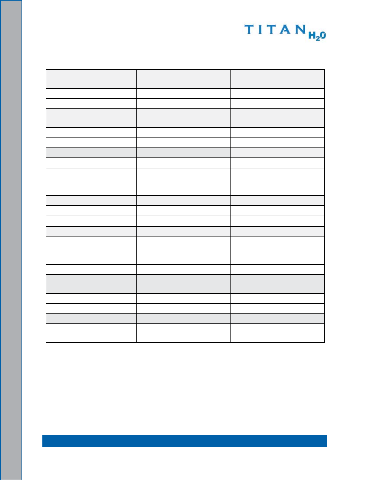
MaCHInE SPECIFICaTIOnS
frame Dimensions 26.0" W x 45" D x 39" H
(66 cm x 114 cm x 99 cm)
Weight 775 lbs (352 kg)
engine - Kubota Oil Type 5W-30 Synthetic
Capacity 3.2 quarts (3.02 litres)
when changing oil and lter
engine rpm High - 3,000 rpm
Idle - 1,500 rpm
fuel Consumption 1.78 gph (6.74 litres/hr)
Ignition Keyless
Vacuum blower - Tuthill
4007 Competitor (Dual
Oil Type
Max. Vac. 14” Hg
Pneulube or other ISO 100
rating
Splash lubrication)
Gear end Capacity Approx. 5.8 oz. (171.5 ml)
Drive end Capacity Approx. 4.7 oz. (139 ml)
blower rpm 3,000 rpm
Standard equipment
Vacuum Hose 2" Vacuum Hose - 100 ft.
(5.08 cm Vacuum Hose -
30.5 m)
Recovery Hose 10 ft (3.05 m)
Recovery Tank 100 gallon Universal Tank
(379 litre Universal Tank)
battery box
Van Decal
Van Installation Kit
Owner’s Manual (on CD)
Owner’s Guide (printed)
1-11: General Information
Page 18

OPTIOnaL EqUIPMEnT
To better meet your business needs, HydraMaster offers several options that you can
add to your basic Titan H2O system. The following shows the available options and the
additional kits necessary to install the options. Refer to the following table before placing
your order for optional equipment.
If you want this option: Order this P/n:
2.5” Vacuum Hose Adapter (100
Gallon Recovery Tank)
Automatic Pump Out (APO)
000-078-875 Kit, 2.5” 3 Port Hose and
000-041-466, Cover Assembly
000-079-091 Pump, Dura-flow APO
exhaust Thru floor 000-078-414 exhaust Thru floor Kit
If you have questions or need assistance conguring your system, please contact your
distributor.
General Information: 1-12
Page 19
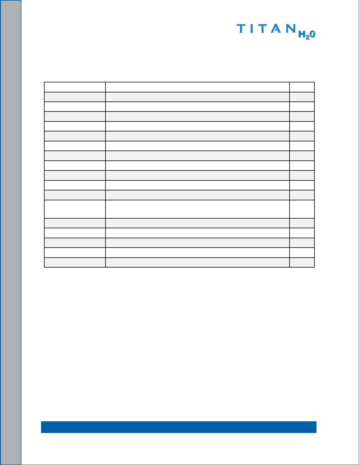
SPaRE PaRTS
The following table is a list of available Titan H2O spares that distributors may purchase
to have on hand for repairs and maintenance.
Part no Description qty
000-010-131 belt, 3vx450 eng. Drive 3
000-025-003 Cable, Choke, With Detent 1
000-049-002
000-049-063
000-049-256
000-049-152
000-049-153
000-056-011
000-057-177
filter, fuel 1
filter, Air - Kubota 1
filter, Oil - Kubota 1
filter, basket, Recovery Tank 1
filter, Stainless Steel Vacuum Pump 1
fuse, 30 Amp Circuit 2
Gasket, exhaust Doughnut 1
000-073-011 Impeller, Replacement, APO 1
000-074-025 Gauge, Vacuum 0-30” Hg 1
000-087-006
HydraMaster-recommended lubricant blower Spray - part
1 ea
number is for 1 can
000-157-022 Switch, Relay 1
000-157-040 Switch, 12V DC, On/Off 1
000-157-131 Switch, 12V DC, Throttle 2
000-157-152 Switch, Ignition, 3-Way 1
000-169-022
Valve, 1 1/2" full Port 1
HIgH aLTITUDE OPERaTIOn
elevation plays a key role in how the truckmount will operate. Operation at high altitude
(above 5,000 ft [1,524 m]) may require a high-altitude carburetor jet. Use of this jet at high
altitude will improve power, reduce fuel consumption and help reduce excessive carbon
build-up in the exhaust system.
Contact the local Kubota dealer or HydraMaster to obtain the proper jet size. find your
local Kubota dealer at http://www.kubotaengine.com/distributor/engine_usa.html.
1-13: General Information
Page 20

WaSTE WaTER DISPOSaL aDVISORY
There are laws in most communities prohibiting the dumping of recovered “gray” water
from carpet cleaning in any place but a sanitary treatment system.
The cleaning rinse water, recovered into your unit’s vacuum tank, contains materials
such as detergents, and must be safely processed before entering streams, rivers and
reservoirs.
In most cases, an acceptable method of waste water disposal is to discharge into a
municipal sewage treatment system after rst ltering out solid material such as carpet
ber. Access to the sanitary system can be obtained through a toilet, laundry drain, RV
dump, etc. Permission should rst be obtained from any concerned party or agency.
One disposal method which usually complies with the law is to accumulate the waste
water and haul it to an appropriate dump site. Another solution to the disposal problem is
to equip your Titan H2O with an Automatic Pump-Out System (APO). These systems are
designed to remove waste water from the extractor’s recovery system and actively pump
the water through hoses to a suitable disposal drain.
HydraMaster makes an APO System which can be ordered with new equipment or
installed later.
When properly congured, the systems will continuously monitor the level of waste water
and pump it out simultaneously with the cleaning operation. The hidden benet of this
process is that the technician does not have to stop his/her cleaning to empty the recovery
tank.
IN ACCORDANCe WITH ePA, STATe AND lOCAl lAWS, DO NOT DISPOSe Of
WASTe WATeR INTO GUTTeRS, STORM DRAINS, STReAMS, ReSeRVOIRS,
eTC.
The penalties for non-compliance can be serious. Always check local laws and
regulations to be sure you are in compliance.
General Information: 1-14
Page 21
2 - Installation Information
Although there are many different heavy duty vehicles used for water restoration
equipment, the preferable vehicle for a Titan H2O installation is a cargo van with a heavyduty suspension package and a minimum of 3/4 HD ton capacity.
Prior to installation of the Titan H2O, HydraMaster recommends installing a spray-on bed
liner in the vehicle. This provides ‘metal to cushion’ mounting rather than ‘metal to metal’
and makes for an attractive van interior.
HydraMaster also recommends installing roof vents in vehicles operated in hot weather
locations. Roof vent positions are shown in
Consult your local RV distributor about selection and/or
installation of powered roof vents.
for best results, the fan should draw air into the vehicle
which will supply cooler air to the air cleaner intake.
OPERaTIng THE TITan H2O In HOT WEaTHER
HydraMaster recommends the following steps when
operating the Titan H2O during periods of hot weather (95º f
[35º C] or higher). This will help ensure that your Titan H2O
continues to run at 100% capacity during even the hottest
days.
figure 2-1.
Location of Figure 2-1.
Roof Vents in Vehicle
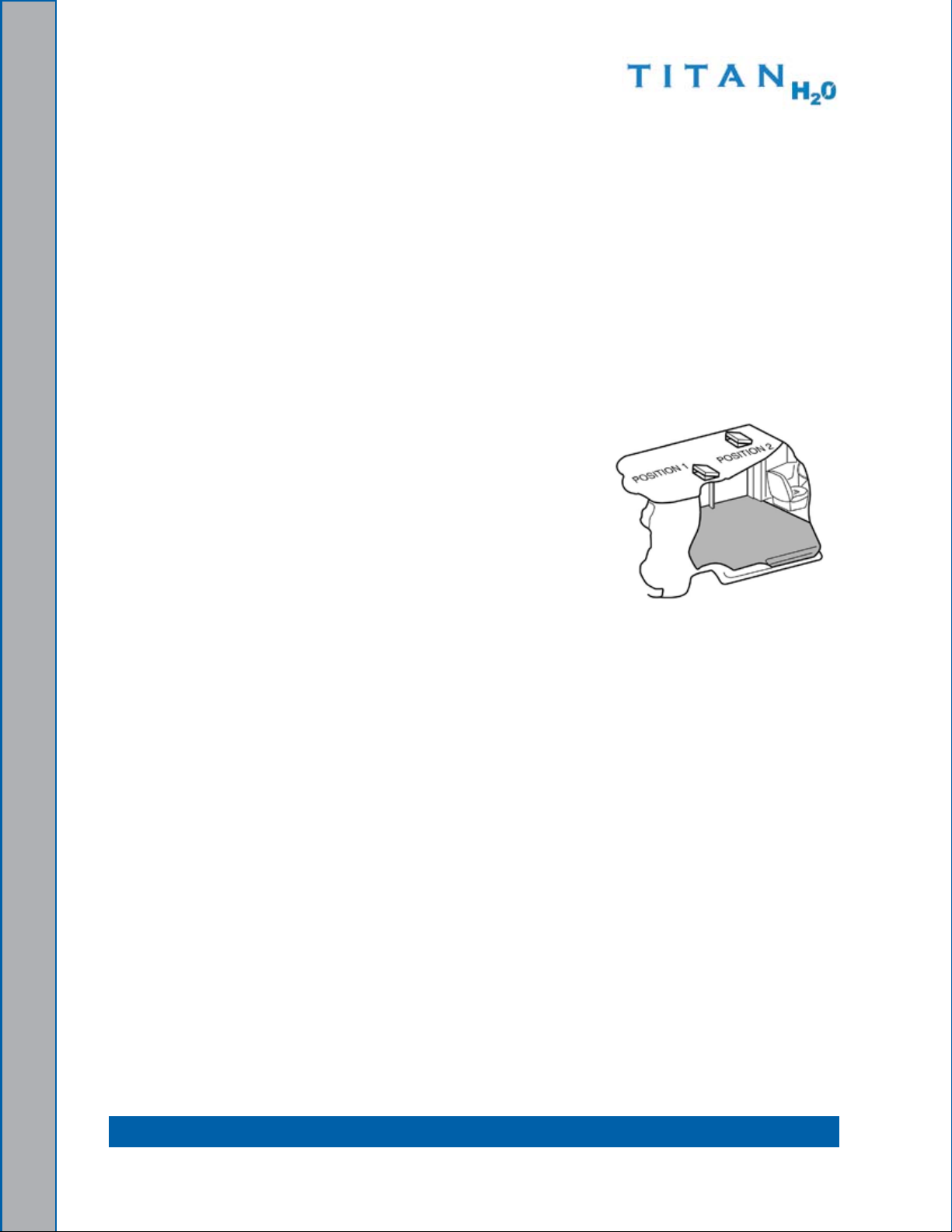
A minimum of 9” (22.9 cm) of clearance is required on both sides of the Titan 1. H2O,
when installed. ensure that additional equipment or other materials are not stored
at the sides or on top of the Titan. Unobstructed airow around the unit is critical for
cooling the engine and other components.
for side-door vans with “barn doors”, open the doors as wide as their construction 2.
will allow. be sure to open the doors beyond their standard “straight-out” position,
if possible, by releasing the stops and putting the doors in their fully extended
position.
Provide cross-ventilation. When possible, keeping the rear doors open while the
3.
Titan is running will substantially reduce the temperature inside the van and will
provide a path for cooling air ow. For rear-mount installations, open up the other
doors in the van.
Consider adding powered roof vents to the vehicle (if not already installed). These
4.
vents can signicantly reduce interior temperatures and will result in much cooler
operation.
2-1: Installation Information
Page 22
Use caution when drilling any holes through the van oor. Many vans have critical
components mounted directly below the vehicle oor that could be damaged by
a misplaced drill bit.
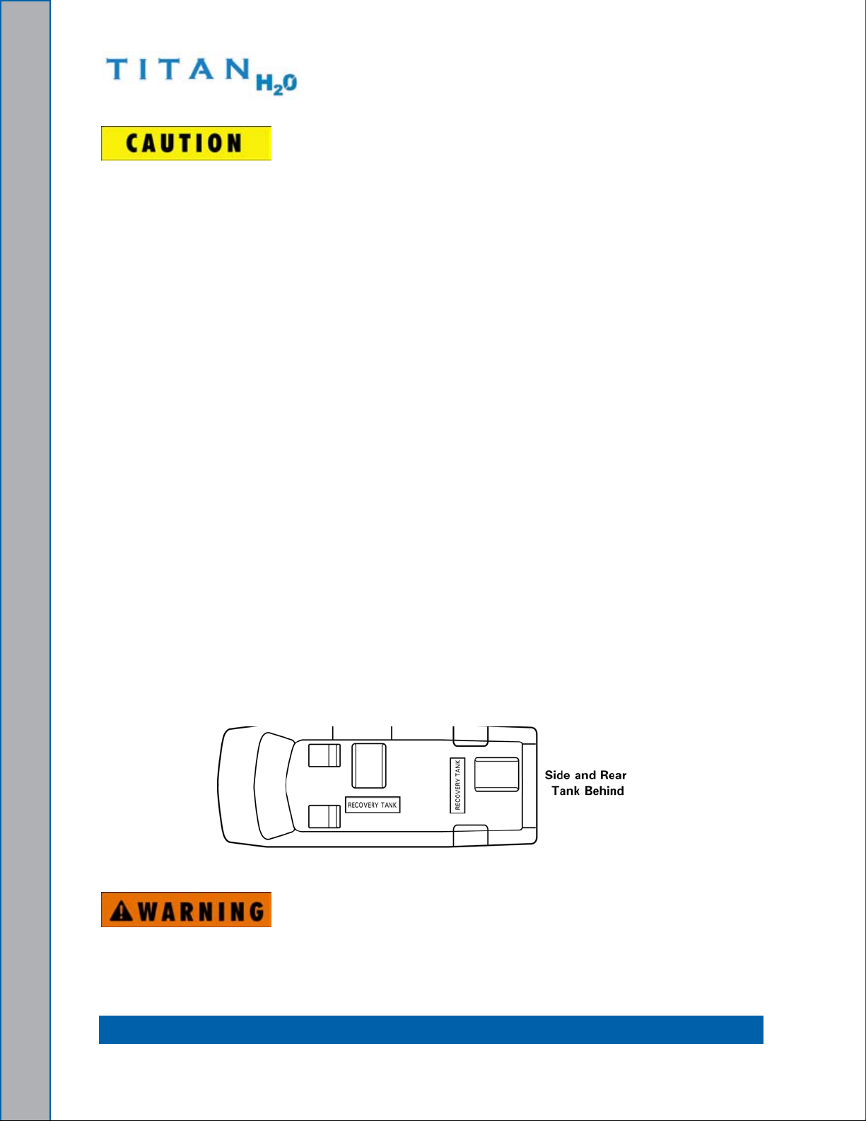
LOCaTIng THE TITan H2O In VEHICLE
There are two recommended entry points on the vehicle for the Titan H2O installation: the
side door or the rear doors.
Most installations are through the side door. This provides rear access for accessories
and hoses as well as unobstructed access to the component/working side of the machine,
thus making it a bit easier to perform maintenance and/or repair without removing the unit
from the truck.
Rear mounting requires the unit to be slid to the right side as far as possible Although
installing the Titan H2O through the rear door partly limits working access, it does direct
the noise away from the cleaning site.
In addition, rear mounting not only provides adequate working space on the component
side of the unit but also improves weight distribution inside the van (engine and component
weight line up over drive shaft). Some water restoration companies in colder geographical
areas prefer this placement for better traction in ice and snow. Also, it is physically easier
to load the unit into the rear door due to the height of the vehicle bed.
Secure Installation
No matter how the unit is installed, check to see if the Titan H2O is properly secured to
the oor of the van with the hardware provided. This safety measure will ensure that the
machine will not slide inside the van. See figure 2-2 for the correct installation.
Figure 2-2. Recommended Location of Titan H2O in Van
A sudden or crash stop will cause the machine to rocket forward if not properly
secured. To prevent serious personal injury, ensure that the Titan H2O is well
secured to the oor of the vehicle with the hardware supplied. Protect yourself
and the machine.
Installation Information: 2-2
Page 23

HydraMaster strongly recommends that the exhaust from the front of the machine
be vented down under the truck to prevent carbon monoxide from entering the
job site. always park the truck so the exhaust is blowing away from the job
site.
Never operate this machine with a portable gas can inside the truck. Doing so
increases the risk of a re or explosion.
Mount a re extinguisher just inside the rear or side door for emergencies.
Do not use a portable propane tank inside of the truck or van. It is dangerous and
illegal in most states.
Transporting any vented fuel container that presently holds or has ever held a
ammable liquid in a vehicle containing the Titan H
O is strictly forbidden by
2
HydraMaster North America, Inc., and by federal and state regulation.
The engine exhaust from this product contains chemicals known to the State of
California to cause cancer, birth defects or other reproductive harm.
SETTIng UP THE TITan H2O
Prior to operating the Titan H2O, adjust the vacuum relief located on the recovery tank by
capping all the vacuum inlets. The machine should be set to 14” Hg maximum.
Setting the vacuum level higher than the recommended value can result in an
increased risk of serious component damage.
2-3: Installation Information
Page 24
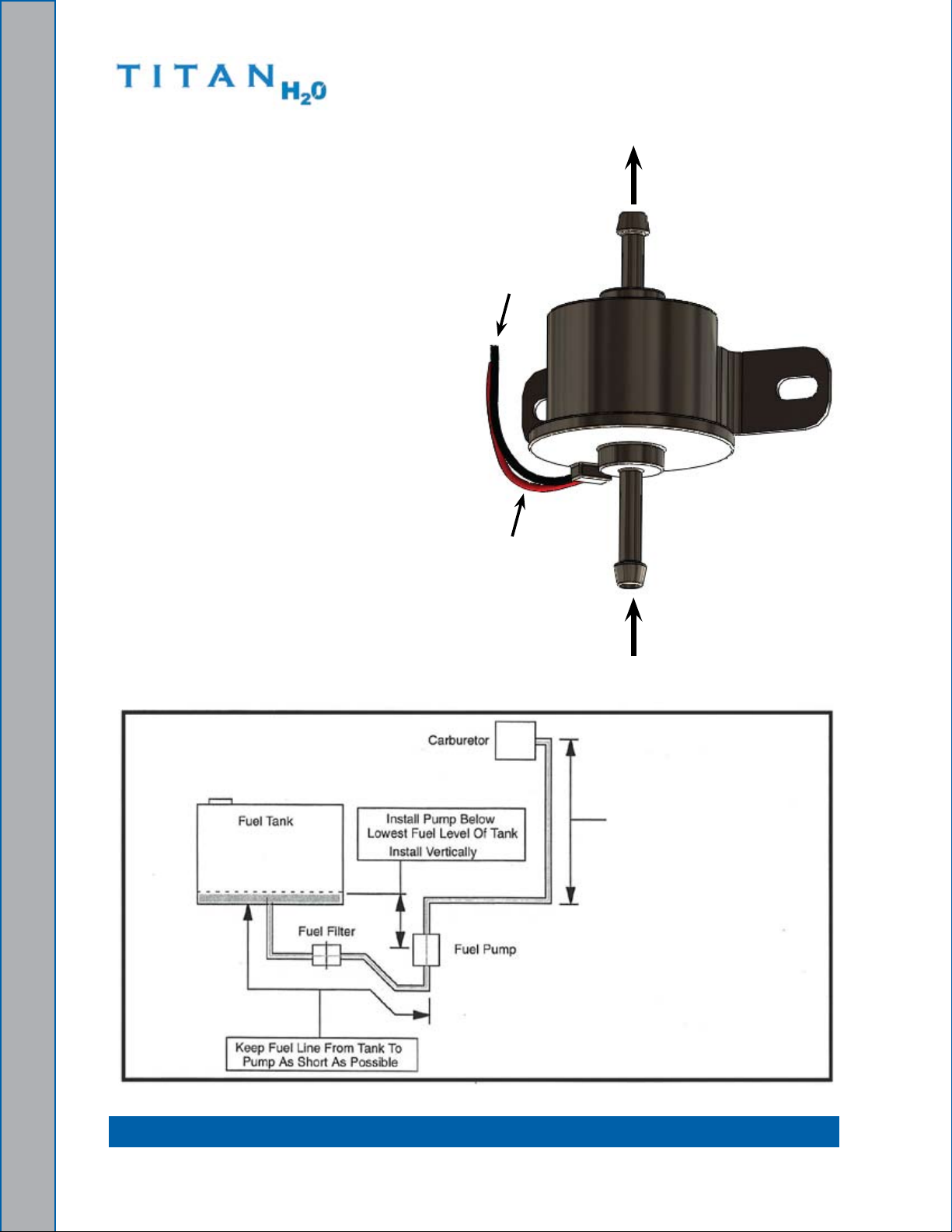
ORIEnTaTIOn OF FUEL PUMP
for proper fuel pump operation and
fuel ow, the vehicle’s fuel pump must
be installed in a lower position with
respect to the fuel tank and in as vertical
a position as possible (outlet side up see
figure 2-3 and figure 2-4).
Mount the fuel pump away from sources
of heat
.
Out
Black = negative
Red = Positive
In
Figure 2-3. Install Fuel Pump, Outlet Side Up
Pump Can Push fuel
6.5 ft (2 m) Vertically
Figure 2-4. Fuel Pump Must Be in Vertical Position
Installation Information: 2-4
Page 25
3 - Operating Instructions
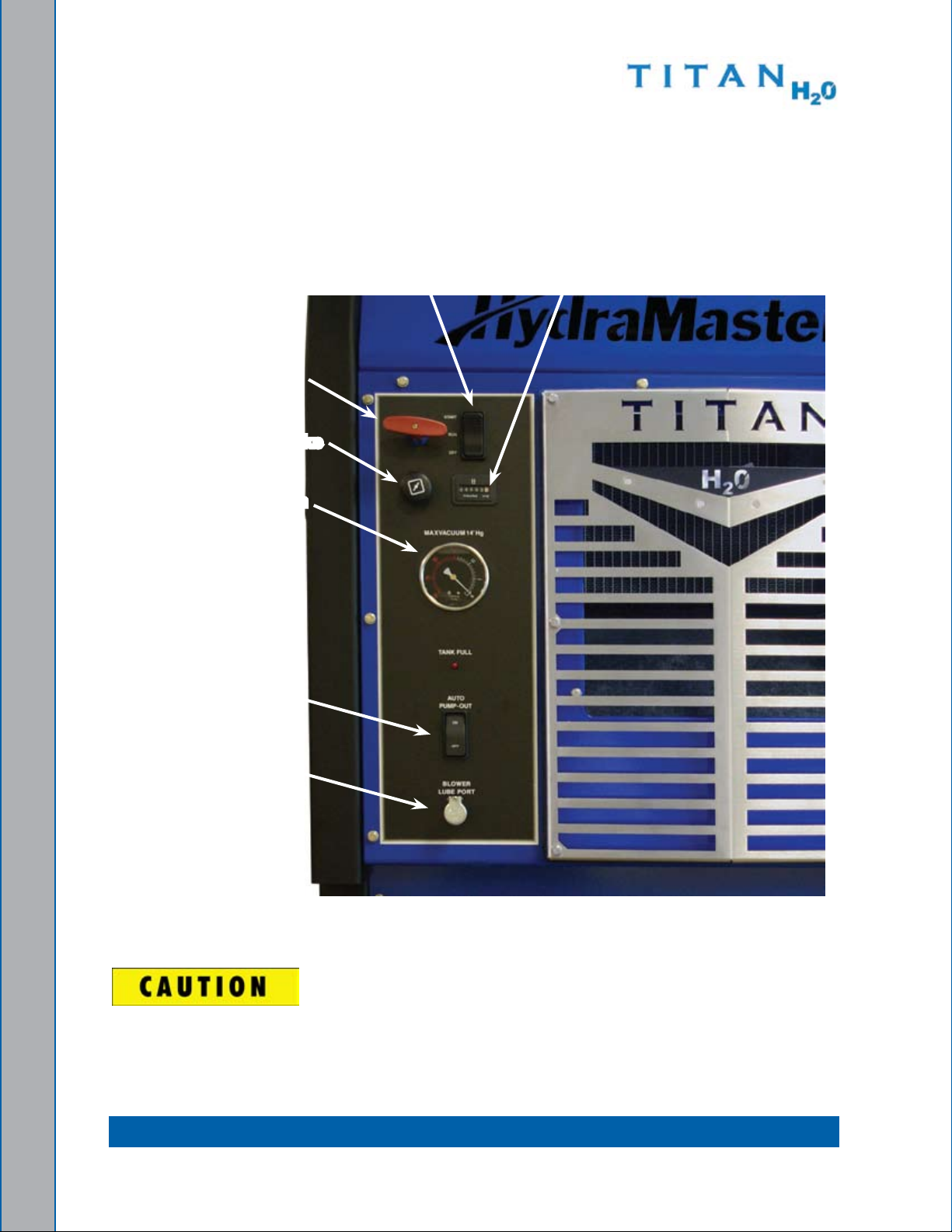
This section describes how to operate the Titan H2O, starting with a physical layout of the
front panel (see
figure 3-1).
Throttle Cable
Choke
Vacuum
gauge
automatic Pump-
Out Switch
Ignition Switch
Hour Meter
Blower
Lube Port
Figure 3-1. Titan H2O Front Panel assembly
The machine cannot be run in the “IDle” position for water extraction. This will
void the warranty.
3-1: Operating Instructions
Page 26

Start Up procedUre
Turn the throttle cable to the “IDLE” position. 1.
Pull the choke cable out if the engine is cold.2.
Start the engine by pushing the ignition switch to “START”. Allow the Titan 3. H2O to
run in idle for 2 – 3 minutes to warm up.
Connect the required length of hoses.
4.
Connect the wand or tool.5.
If the Automatic Pump-Out option is included in your conguration, turn the Automatic 6.
Pump-Out (APO) switch to “ON”
Pull the throttle cable to the “HIGH” speed position.
7.
Commence water extraction.8.
ShUt down procedUre
Remove the vacuum hose.1.
Lubricate the blower to prevent it from rusting internally.2.
Allow the unit to run at high speed for a few minutes with the vacuum hose a.
disconnected in order to remove moisture from the blower.
Cap off the inlet(s) to the vacuum tank.
b.
Spray a HydraMaster-recommended spray lubricant into the “BLOWER LUBE c.
PORT” for about 5 to 10 seconds while the unit is running.
Allow machine to run additional 2 to 5 minutes under load to ush off lubricant.
d.
Uncap the inlet(s) and run the unit for another minute to allow the blower to cool e.
down.
Push the throttle cable to the “IDLE” position.
3.
Turn the ignition switch to “OFF.”4.
Drain the vacuum tank in an appropriate location.5.
In accordance with EPA, state and local laws, do not dispose of water into gutters,
storm drains, streams, or reservoirs.
Clean the vacuum lter prior to mobilizing the van.
6.
Perform daily and periodic maintenance as specied in Section 7. 4 of this Owner’s
Manual.
Operating Instructions: 3-2
Page 27

4 - Machine Maintenance
To avoid costly repairs and downtime, it is imperative to develop and practice good
maintenance procedures. These procedures fall into daily, weekly, monthly and quarterly
increments and are outlined below. All maintenance must be performed by qualied
service personnel.
A maintenance log, provided in the Owner’s Guide, must be correctly and completely lled
out. HydraMaster may request to inspect the logs before a warranty claim is honored.
It is recommended that the log be afxed to the vehicle door near the truckmount for
convenience and to serve as a maintenance reminder.
This section describes how to properly maintain the truckmount in the following areas:
Operational Maintenance
Overall Machine Maintenance
Vacuum System Maintenance
4-1: Machine Maintenance
Page 28

OPERaTIOnaL MaInTEnanCE
Daily Maintenance
Check the engine oil level. Add oil if needed.
•
Check the oil level in the blower. Add oil if needed.•
Check coolant overow bottle level. Add coolant if needed.•
Inspect and clean the recovery tank lters.•
Inspect the truckmount for water and oil leaks, loose electrical connections, etc. and •
repair as needed.
lubricate the blower with a HydraMaster-recommended lubricant. •
Weekly Maintenance
Inspect the recovery tank lters for tears, holes, etc. Repair or replace as needed.
•
Inspect the vacuum relief valve. Clean and lubricate as necessary.•
Clean the recovery tank thoroughly with pressure washer.•
Check the blower belt drive and fan belt for wear and proper tension. Adjust as •
needed.
Check all the hoses and wiring for wear and chang. Secure as needed.
•
Check all the nuts and bolts. Tighten as needed.•
One time change of the engine oil after 25 hours of operation.•
Change the engine oil every 100 hours. (every 50 hours if operating in high ambient •
temperatures.) Change oil lter every oil change.
Monthly Maintenance
Check the engine air lter. Clean or replace as necessary.
•
Check the water level in battery. fill as needed.•
Clean the battery terminals as needed.•
quarterly Maintenance
Check the fuel lines. Repair or replace as needed.•
Clean and gap the spark plugs to 0.031 - 0.035” (0.8 - 0.9 mm). Replace if excessive •
carbon buildup is visible.
Change the blower oil after rst 100 hours of use.
•
Machine Maintenance: 4-2
Page 29

500 Hours
Change the blower oil.•
Check the engine valve clearance (intake and exhaust 0.012” [0.30 mm])•
Replace spark plugs•
Change primary fuel lter•
Change coolant•
1,000 Hours
Replace spark plugs
•
Change primary air lter•
flush coolant system•
OVERaLL MaCHInE MaInTEnanCE
Maintenance, troubleshooting and repair are much easier tasks to accomplish on a clean
truckmount. Regular cleaning of the truckmount offers the user an opportunity to visually
inspect all facets of the truckmount and spot potential problems before they occur. In
addition to the operational maintenance the following “housekeeping” duties should be
performed.
after each job
Check the recovery tank and the recovery tank lters. Empty and clean as •
necessary.
Daily
Wipe the Titan H
•
Wipe down the vacuum hoses as needed.
•
O down thoroughly with a damp cloth.
2
Inspect and clean the vacuum slot on the wand or tool.•
Clean your wands and tools to maintain original appearance.•
Visually inspect the hoses for abrasions, cuts, etc. Repair or replace as needed.•
Weekly
Thoroughly clean all wands and tools, and inspect for debris in vacuum slot.
•
Thoroughly clean the vacuum hoses.•
4-3: Machine Maintenance
Page 30

EngInE MaInTEnanCE
Engine Oil Level Check
The engine oil level should be checked daily. It is recommended that the oil be checked
just before the engine is started for the rst time for that day. The oil level should be
between the ‘Add’ and the ‘full’ marks on the dipstick.
Do not operate the engine with the oil level below the bottom of the ‘Add’ mark on
the dipstick, or above the top of the ‘full’ mark.
adding Engine Oil
It is normal to add some oil in the period of time between oil changes. The amount will
vary with the severity of operation. When adding or replacing engine oil, be sure the oil
meets or exceeds the recommended specication.
Changing Engine Oil and Filter
The engine oil and lter must be changed every 100 hours or every 3 months whichever
occurs rst. The oil and lter should be changed more often if the engine is operating in
dusty or extremely dirty areas, or during cold weather.
Engine Oil quality
To achieve proper engine performance and durability, it is important that you use only
engine lubricating oils of the correct quality in your engine. Proper quality oils also provide
maximum efciency for crankcase ventilation systems, which reduces pollution.
Use only engine oils displaying the American Petroleum Institute (API) “starburst”
certication mark ‘FOR GASOLINE ENGINES’ on the container.
engine Oil Recommendation
While multi-viscosity oils are generally recommended, SAE 5W-30 synthetic is specically
recommended year round for your Titan H2O engine.
Machine Maintenance: 4-4
Page 31

Oil Filter
Kubota engines use a Kubota oil lter. An equivalent or better oil lter must be used when
servicing the engine.
To replace the lter, use a proper lter wrench to remove the lter.
Clean the lter mounting base and lightly coat the gasket surface of the new lter with
engine oil. Hand tighten the lter until the gasket contacts the base, then tighten another
½ turn. fill the engine with the correct amount of oil, run the engine and check for oil leaks
at the drain plug and oil lter gasket.
Spark Plugs
Always use the recommended spark plugs for your engine. Hotter or colder plugs, or similar
plugs that are not exact equivalents to the recommended plugs, can cause permanent
engine damage, reduce the engines useful life, and cause many other problems such as
hard starting, spark knock and run-on. Installing new spark plugs regularly is one of the
best ways to keep your engine at peak performance.
Cooling System
Coolant level
Check the coolant level in the coolant overow reservoir daily. Generally a good time to
do this is just prior to starting the engine for the rst time each day.
Maintain the coolant level in the radiator at ¾ “ (19 mm) below the ller neck seat of the
radiator when the coolant is cold. When the coolant level is checked, inspect the condition
of the radiator caps rubber seal. Make sure it is clean and free of any dirt particles which
would keep it from seating on the ller neck seat. Rinse off with clean water if necessary.
Also make sure that the ller neck seat is free of any dirt particles.
Never remove the radiator cap under any condition while the engine is operating.
failure to follow these instructions could result in damage to the cooling system,
engine, or cause personal injury. DO NOT add coolant to any engine that has
overheated until the engine cools.
The engine manufacture recommends the cooling system to be lled with a 50/50 mixture
of antifreeze and water.
4-5: Machine Maintenance
Page 32

Always maintain a 50% solution of phosphate-free antifreeze at all times for
adequate heat dissipation, lubrication and protection from freezing. Major brands
are typically low phosphate or phosphate free, and will be labeled accordingly
on the container. It is recommended that you consult the technical data sheet
for the brand of coolant you are using to determine if it meets the low phosphate
requirement. failure to use a 50% solution of phosphate-free antifreeze may
result in corrosion of the cooling system.
bleeding Air from Cooling System
It is necessary to remove all of the air from the engine to prevent overheating. If the coolant
has been drained for any reason, it will be necessary to follow the bleed procedure.
When the engine is cold, remove the radiator cap. fill the radiator until it is to the top of
the ller neck. Start the engine and run in the idle rpm position and no vacuum load. Allow
the engine coolant to heat up and open the thermostat several times. As all the air is
removed from the system, the level of the radiator should lower below the internal tubes.
This process should take approximately 5 - 10 minutes. Top off the coolant and install the
cap. In the event you experience a coolant shutdown due to overheat, allow the machine
to cool down and repeat this procedure.
Radiator
Inspect the exterior of the radiator for obstructions. Remove all debris with a soft brush or
cloth. Use care to avoid damaging the core ns.
Fuel Filter
The fuel lter is located between the fuel pump and the fuel tank underneath the vehicle.
Machine Maintenance: 4-6
Page 33

VaCUUM SYSTEM MaInTEnanCE
The vacuum pump in this machine is commonly referred to as a “rotary positive
displacement blower” or “blower” for short. The performance and life of the truckmount is
greatly dependent on the care and proper maintenance it receives. The manual for the
blower has been included. Review the manual for a better understanding of this piece of
machinery.
To protect the blower from overloading and damaging itself, there is a vacuum relief
system installed on the vacuum tank. When the vacuum tank inlet is completely
sealed off a maximum of 14” Hg will be attained.
Solid objects entering the blower will cause serious damage to the internal
components of the blower. extreme caution should be used when the truckmount is
being run for test purposes with the inlet to the blower open to the atmosphere.
foam passing through the blower can lead to serious problems with the truckmount.
It is important to keep the vacuum tank free of foam. The tank is protected from
overowing by a oat kill switch; however, this switch is not activated by foam.
Daily
At the end of each day the internal components of the blower need to be lubricated. This
helps to prevent rust deposits and prolongs the life of the truckmount.
To lubricate the blower:
Allow the unit to run for a few minutes at high speed with the vacuum hose
1.
disconnected in order to remove moisture from the blower.
Cap off the inlet(s) to the vacuum tank.
2.
Spray a HydraMaster-recommended spray lubricant into the “blOWeR lUbe 3.
PORT” for about 5 to 10 seconds while the unit is running.
Allow machine to run additional 2 to 5 minutes under load to ush off lubricant.
4.
Uncap the inlet(s) and run the unit for another minute to allow the blower to cool 5.
down.
Periodically
Change the oil in both ends of the blower after the initial 100 hours of use. The oil is to be
changed each 500 hours of use thereafter.
4-7: Machine Maintenance
Page 34

Machine Maintenance: 4-8
Page 35

5 - electrical System
This section describes how the electrical system functions in the following manner:
electrical System Information
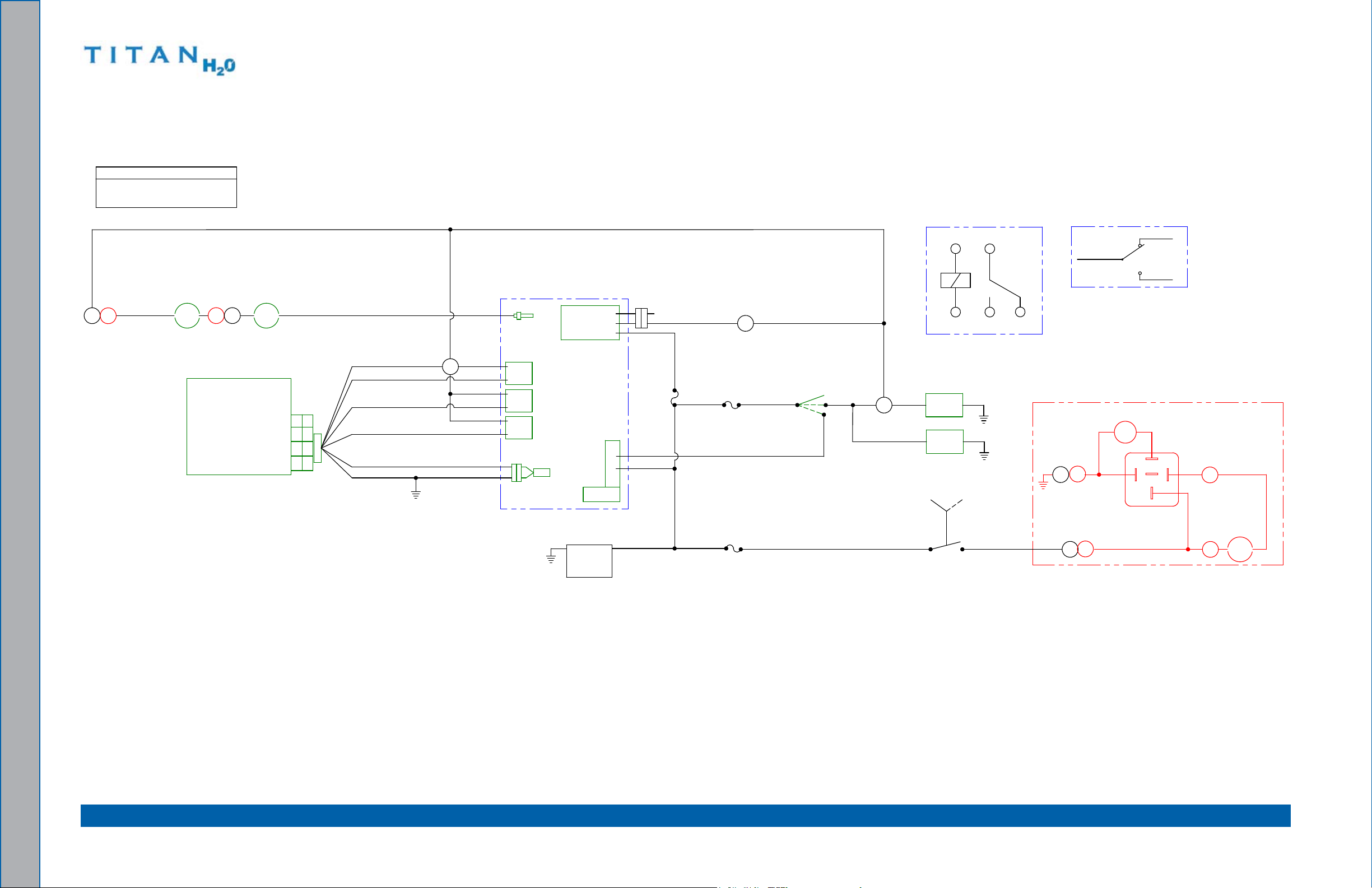
electrical Schematic
Wiring Diagram
ELECTRICaL SYSTEM InFORMaTIOn
The Titan H2O electrical system operates on 12 - 14 V DC which is provided by the battery.
battery levels are maintained by a 40-Amp alternator mounted on the engine.
When a new battery is installed, check that it is properly charged before installation
or damage to the charging system may occur.
5-1: electrical System
Page 36
000-179-853
TB1
-2
TB2
-2
TB2
-1
TB1
-4
TB1
-2
TB1
-3
TB1
-1
TB2
-6
TB2
-3
TB3
-6
TB3
-5
TB3
-2
TB3
-1
HOUR
METER
HI-1
GND
GREEN - DENOTES COMPONENTS
BLACK - DENOTES WIRES
COLOR KEY
RED - DENOTES OPTIONAL EQUIPMENT
KUBOTA ENGINE
MTR-1
FU-1
SENSOR
+-
FUSE
MAIN 30A
ALTERNATOR
OVERHEAT SWITCH
SOLENOID
ALT-1
SOL-1
STARTER
PS-1
V-1
B
ST
IG
L
B
#3
STARTER
+
-
BATTERY
FS-1
IGN. COILS
-
+
240° ENGINE
+
-
SOLENOID
EGF
I
KHL
J
N/C
#2
CRANK RPM
SW-1
ST
BAT
N/C
12V
IP-1
ON
CARB.
50A
FU-2
SW-4
#1
IGNITION SWITCH
BREAKER
VACUUM TANK
HIGH WATER FLOAT
IGNITION
PROCESSOR
CIRCUIT
FUEL
PUMP
PMP-1
85
FS-2
APO
PMP-2
AUTO PUMP OUT OPTION
FLOAT
CR-1
N/O
87a
GND
30
86
87
AUTO PUMP OUT
RELAY
AUTO PUMP OUT
GREEN
WHITE
F
L
J
G
E
GND
GND
BLACK
FLOAT SWITCH
FU-3
86
K
APO 30A
SW-2
ONOFF
N.C.
FUSE
SWITCH
(SHOWN IN "OFF" POSITION)
30
87A
87
85
N.O.
RELAY SCHEMATIC
AUTO PUMP OUT
RECOVERY TANK
GND
Electrical Schematic Figure 5-1.
electrical System: 5-2
Page 37
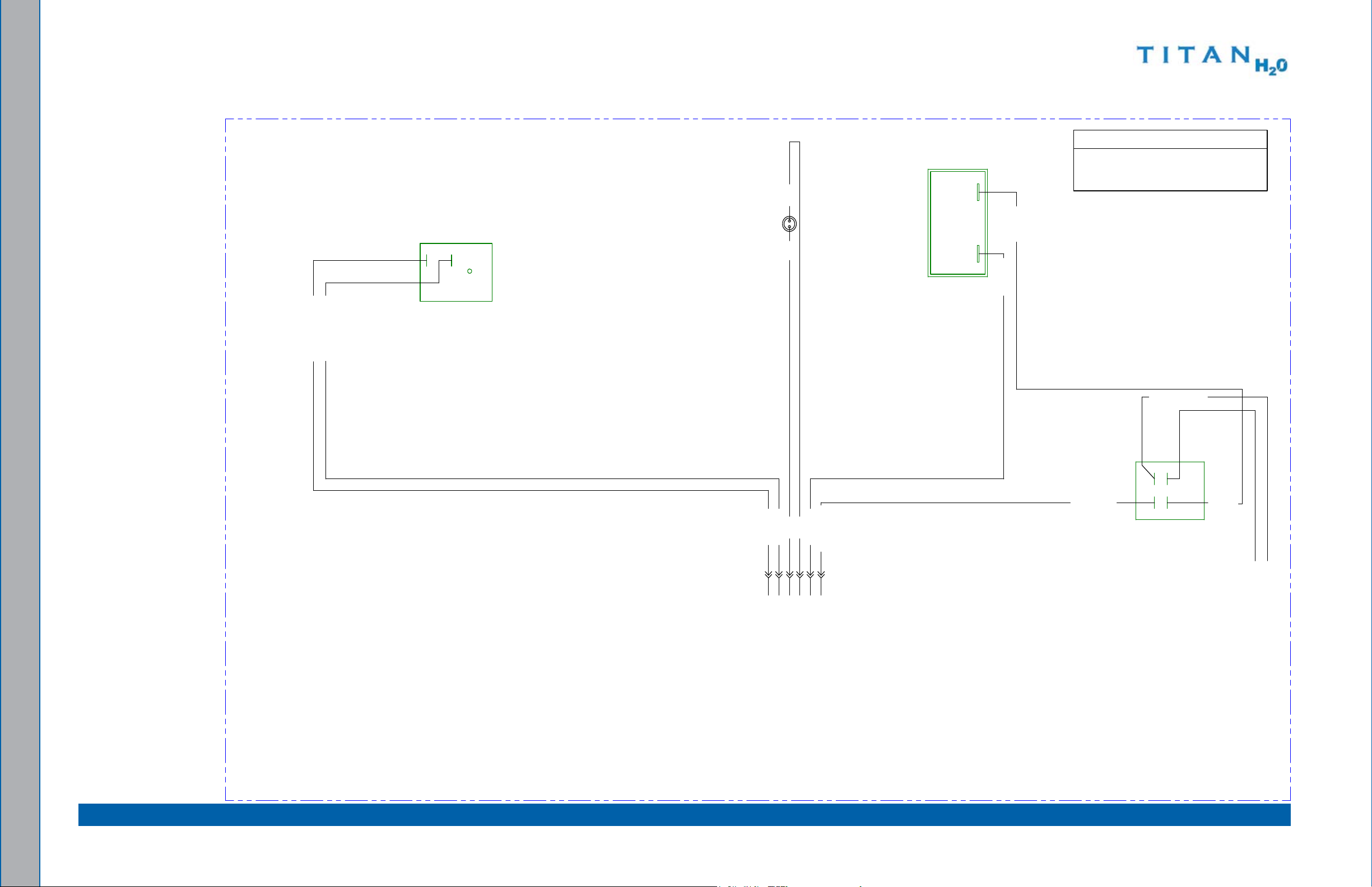
Wiring Diagram - View 1 of 3 Figure 5-2.
COLOR KEY
RED - DENOTES OPTIONAL EQUIPMENT
GREEN - DENOTES COMPONENTS
BLACK - DENOTES WIRES
*ALL WIRES ARE 18 GAUGE UNLESS OTHERWISE STATED
P-13 J-13
(ON)
(BAT) (ST)
(IGN)
5
6
SWITCH
IGNITION
SW-1
3
2
2
3
SWITCH
PUMP OUT
SW-2
HOUR METER
HI-1
P-10 J-10
P-16 J-16
P-15 J-15
P-14 J-14
P-12 J-12
(R
E
D
)
42(BLK)
42(BLK)
41(WHT)
46(BRN)
47(BLK)
46(BRN)-14 GA.
47(BLK)-14 GA.
11(RED) 12 GA.
11(RED) [TO FU-1 - 12 GA.]
45(BLU/BLK)
33(BLK/WHT) [TO TB1-1]
41(WHT)
(BLK)
L
-
1
].AG 41 )NRB(05
10(BLK) [TO APO FUSE FU-3 - 14 GA.]
29(BLK/WHT) [TO TB-1 #5]
28(WHT) [TO TB-1 #6]
48(BLU/BLK) [TO STARTER SOLENOID SOL-1]
49(RED) [TO TB-2 #4]
(RED)
45(BLU/BLK)
[TO RECOVERY TANK TB-2 #6 -
R
E
C
O
V
E
R
Y
T
A
N
K
F
U
L
L
L
I
G
H
T
(
B
L
K
)
000-179-852
5-3: electrical System
Page 38
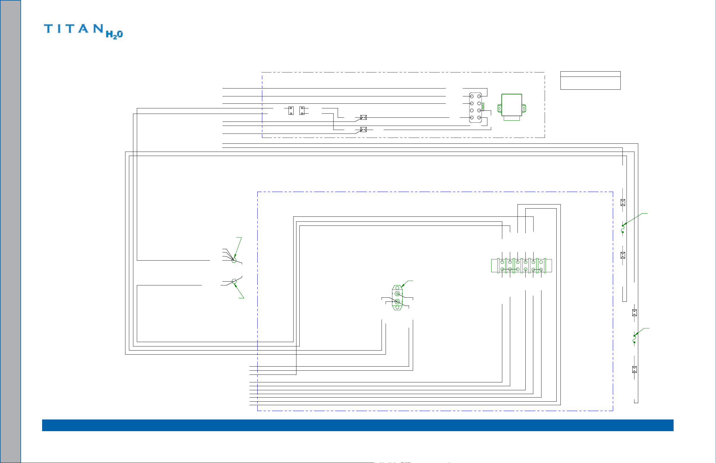
Wiring Diagram - View 2 of 3 Figure 5-3.
E
F
K
J
GH
I
L
PROCESSOR
IGNITION
IP-1
RED - DENOTES OPTIONAL EQUIPMENT
GREEN - DENOTES COMPONENTS
BLACK - DENOTES WIRES
COLOR KEY
ELECTRICAL BOX
KUBOTA WIRING HARNESS
(BEHIND ELECTRICAL BOX)
(ORG)
(ORG)
61524
3
TB-1
(ORG) (ORG)
BREAKER
CIRCUIT
FU-2
50A
MAIN 30A
IN-LINE FUSE
FU-1
APO 30A
IN-LINE FUSE
FU-3
GND-2
GND-1
COPPER STUD
ORIENTATED
TOWARDS TOP
OF BREAKER
ORIENTATION
REF. FROM
BACK OF PLUG
[TO ENG GROUND GND-3 - 12 GA.] 37(WHT)
[TO FUEL PUMP "+"] 16(RED)
13(BLK) 12GA.
[TO IGN. SWITCH SW-1 #3 - 12 GA.] 11(RED)
11(RED) 12GA.
[TO J15 - 14 GA.] 10(BLK)
[TO FUEL PUMP PMP-3] 35(WHT/GRN)
[TO TB-2 #3 14 GA.] 36(WHT)
24(WHT/BLU)
33(BLK/WHT) 12 GA
32(ORG/WHT)
30(ORG)
22(GRY/BLK)
B-4
23(PNK/BLK)
16(RED)
21(PUR/BLK)
*ALL WIRES ARE 18 GAUGE UNLESS OTHERWISE STATED
15(RED) 10 GA
14(BLK) 12 GA
[TO STARTER SOL "B" - 12 GA.] 14(BLK)
[TO ALTERNATOR "B" - 10 GA.] 15(RED)
10(BLK) 14GA.
13(BLK) 12 GA
12(BLK) 14G
A.
B-3
B-2B-1
12(BLK) 14 GA
24(WHT/BLU)
29(BLK/WHT)
28(WHT)
[TO IGN. SWITCH SW-1 #2 - 12 GA.] 33(BLK/WHT)
[TO RECOVERY TANK TB-2 #2] 32(ORG/WHT)
[TO J14] 29(BLK/WHT)
[TO 240° ENG OVERHEAT SWITCH SW-4] 23(PNK/BLK)
[TO ALTERNATOR P5 #IG] 22(GRY/BLK)
[TO J13] 28(WHT)
[TO RECOVERY TANK TB-2 #1] 30(ORG)
39(BLK)
38(BLK)
P-1
[TO CRANK SENSOR P-7 #2] 08(GRN)
09(BLU)
[TO CRANK SENSOR P-7 #1] 09(BLU)
[TO IGNITION COIL #2] 05(WHT/BLK)
[TO IGNITION COIL #3] 06(BLU/BLK)
[TO IGNITION COIL #1] 07(RED/BLK)
05(WHT/BLK)
07(RED/BLK)
02(BLK)
40(RED)
06(BLU/BLK)
[TO IGNITION COIL #1] 01(ORG)
B-6
B-5
40(RED)17(RED)
20(BLK)
39(BLK)
21(PUR/BLK)
20(BLK)
17(RED)
P-2J-2
[TO P-3 "CARB SOLENOID"] 04(WHT/GRY)
000-179-852
electrical System: 5-4
Page 39

000-179-852
BLACK - DENOTES WIRES
RED - DENOTES OPTIONAL EQUIPMENT
GREEN - DENOTES COMPONENTS
COLOR KEY
04(WHT/GRY) 03(WHT/GRY)
26(RED/WHT)
RECOVERY TANK
KUBOTA ENGINE
MTR-1
IGNITION COILS
AUTO PUMP OUT OPTION
53(WHT)-14 GA.
52(BLK)-14 GA.
AUTO
37(BLK)-14 GA.
44(WHT)-14 GA.
27(WHT/RED)
86
30
85
87A
87
53(WHT)-14 GA.
54(BLK)-14 GA.
25(WHT/BLU)
27(WHT/RED)
CR-1
OUT
RELAY
1
3
4
2
6
5
(WHT)
BLOCK
APO TERMINAL
TB-3
P11
A
B
J11
(BLK)
(RED)
PMP-2
PUMP OUT
(BLK)
51(WHT)-14 GA.
APO FLOAT
FS-2
AUTO PUMP
N/O
FLOAT
FS-1
HIGH WATER
VACUUM TANK
TB-2
1
2
3
4
5
6
-
PS-1
+
12V BATTERY
N/C
SOLENOID
CARB
V-1
B
IG
(CENTER
PIN)
ALT-1
ALTERNATOR
P-5
N/C
STARTER
SOLENOID
SOL-1
- + +- - +
COIL
#3 #2
COIL COIL
#1
1
2
IG
ST
B
CRANK RPM
240° ENGINE
ENGINE GND
GND-3
OVERHEAT SWITCH
SW-4
P-7
SENSOR
STARTER
P-6
FUEL PUMP
PMP-1
36(WHT) [TO GROUND @ ELECTRICAL PANEL GND-1 - 14 GA.]
36(WHT)-14 GA.
32(ORG/WHT) [TO TB-1 #2]
30(ORG) [TO TB-1 #4]
50(BRN) [TO J16 -14 GA.]
50(BRN)-14 GA.
32(ORG/WHT)
30(ORG)
(GRN)
(WHT)
19(RED)
18(BLK)
(BLK)
49(RED)
49(RED) [TO J-12]
P-3 J-3
P-4 J-4
04(WHT/GRY) [TO GROUND @ ELECTRICAL PANEL GND-1]
08(GRN)
06(BLU/BLK)
15(RED) [TO FU-2 10 GA]
14(BLK) [TO FU-2 12 GA]
22(GRY/BLK) [TO TB-1 #3]
37(WHT) [TO GROUND @ ELECTRICAL PANEL GND-1 12 GA]
09(BLU) [TO IGN PROCESSOR P-1 #E]
08(GRN) [TO B-5]
01(ORG) [TO B-6]
07(RED/BLK) [TO IGN PROCESSOR P-1 #L]
06(BLU/BLK) [TO IGN PROCESSOR P-1 #J]
05(WHT/BLK) [TO IGN PROCESSOR P-1 #K]
23(PNK/BLK) [TO TB-1 #4]
48(BLU/BLK) [TO J10]
48(BLU/BLK)
19(RED) 6GA.
14(BLK) 12GA.
07(RED/BLK)
05(WHT/
BLK)
15
(RED) 10 GA
22(GRY/BLK)
43(GRN)
23(PNK/BLK)
01(ORG)
18(BLK) 6 GA
37WHT) 12 GA.
09(BLU)
31(ORG)
34(ORG)
16(RED) [TO TB-1 #1]
P-9 J-9
16(RED)
35(WHT/GRN) [TO GROUND @ ELECTICAL PANEL GND-1]
NEG. -
POS. +
35(WHT/GRN)
P-8 J-8
(BLK)
(WHT/BLK)
Wiring Diagram - View 3 of 3 Figure 5-4.
5-5: electrical System
Page 40

electrical System: 5-6
Page 41

6 - Systems Troubleshooting
This section describes the standard troubleshooting procedures in the following areas:
engine
Vacuum System
EngInE
The engine will not turn over1.
Possible Cause Solution
1.1. A loose or corroded
battery terminal.
1.2. The battery is dead. Recharge or replace the battery. Test the charging
1.3. The main fuse is blown. Check the main fuse.
1.4. The vacuum blower has
seized.
1.5. The ignition switch is
faulty.
1.6. The starter solenoid is
faulty.
1.7. .The starter motor is
faulty.
1.8. None of the above. Refer to a qualied service technician for further
Clean and tighten the battery terminal connections.
system. Repair if necessary.
Do not attempt to jump start the truckmount
from a running vehicle. The amperage output
from an automobile will damage the charging
system of the truckmount.
If the fuse is blown, inspect the electrical system
for worn or shorted wires. Repair or replace as
necessary.
Attempt to turn the coupler by hand. If it will not
turn refer to the Vacuum System Troubleshooting
Subsection.
Test to see if there is power both to and from the
switch.
Test to see if there is power to solenoid with ignition
in "START" position.
Test to see if there is power to the motor with the
ignition in "START" position. .
troubleshooting.
6-1: Systems Troubleshooting
Page 42
The engine turns over but will not start.2.
Possible Cause Solution
2.1. The recovery tank is full Drain the tank.
2.2. The recovery tank oat is
Inspect the oat. Repair or replace as necessary.
faulty.
2.3. The engine ignition
system in faulty.
Refer to a qualied service technician for further
troubleshooting.
2.4.
fuel is not reaching the
carburetor.
Test for power to the fuel pump. Refer to electrical
Section.
If power is present, inspect the fuel pump. Replace if
necessary.
Inspect the fuel lines between the source and the
carburetor. Repair or replace as necessary.
2.5. The engine is ooded. Remove spark plug and dry.
2.6. .The spark plugs are worn
Inspect and replace as necessary.
or dirty.
2.7. None of the above. Refer to a qualied service technician for further
troubleshooting.
engine should be adjusted to run at 3,000 rpm under a vacuum load of 14” Hg.
The engine will not come up to normal operating rpm3.
Possible Cause Solution
3.1.
excessive load on the
Inspect and clean the recovery tank lters.
engine.
Inspect the recovery tank to the blower hose. Repair
or replace as necessary.
3.2.
excessive back pressure
on the engine exhaust.
Inspect for blockage in the exhaust system. Clean or
replace as necessary.
Systems Troubleshooting: 6-2
Page 43

Runs rough at high speed4.
Possible Cause Solution
4.1. The spark plug(s) are
faulty.
4.2. . The spark plug wire(s)
are faulty.
4.3. Inadequate fuel supply to
the carburetor.
Remove and inspect the plugs. Clean or replace as
necessary.
Inspect the wires and connectors for damage or
loose connections. Repair or replace as necessary.
Check for blockage in the lter. Repair or replace as
necessary.
4.4. Poor connection to coils. Verify there is a good contact with each of the wires
to the coils.
5.
Runs rich (black smoke)
Possible Cause Solution
5.1. A dirty air lter Inspect and replace as necessary.
5.2.
excessive back pressure Inspect for blockage in the blower exhaust, dirty air
lter or a partially opened choke.
Engine overheats
6.
Possible Cause Solution
6.1. Poor ventilation in the
Open all the van doors.
van
Install a roof vent in the van.
Remove any dividers or other objects impeding
airow around the truckmount.
6.2.
6.3.
low oil level Check the level and ll as necessary.
excessive back pressure
on the engine exhaust
Inspect for blockage in the blower exhaust. Clean or
replace as necessary.
6.4. Check radiator level
Check overow bottle level
6.5. Poor coolant mixture Check the coolant with a test to determine mixture;
adjust as necessary.
6-3: Systems Troubleshooting
Page 44

VaCUUM SYSTEM
Weak vacuum at wand. The gauge reads normal.1.
Possible Cause Solution
blockage in the hoses or
1.1
wand tube
excessive length of
1.2
hose connected to the
truckmount
2.
Weak vacuum
Possible Cause Solution
2.1. Air leak somewhere in the
vacuum system
2.2. The vacuum blower is
turning too slowly.
2.3. The vacuum gauge is
defective.
Disconnect the hoses and check for an obstruction.
Do not attach excessive lengths of hose.
Check the vacuum relief valve for proper adjustment.
Carefully check all the vacuum hoses for a cut or
break.
Check the recovery tank lid gasket.
Make sure the recovery tank drain valve is fully
closed.
Check the rpm of the engine. Adjust as necessary to
3,000 rpm under a 14" Hg vacuum load.
Test the gauge and replace if necessary.
The vacuum gauge reads too high with no hoses attached
3.
Possible Cause Solution
3.1. The lter in recovery tank
Remove and clean or replace as necessary.
is clogged.
3.2. The hose from recovery
Inspect and replace as necessary.
tank to the vacuum
blower is collapsed
internally.
Systems Troubleshooting: 6-4
Page 45
Excessive noise produced by the blower4.
Possible Cause Solution
4.1. The blower is low on oil. Inspect the oil levels and replenish as necessary.
Note: Running the blower with low oil levels can
cause severe damage. If this situation occurs the
blower should be inspected by a qualied service
technician.
4.2 The vacuum blower has
Refer to a qualied service technician.
internal damage.
5.
The vacuum blower is locked and will not turn
Possible Cause Solution
5.1. Truckmount has been
inactive for a period of
time and the blower was
not properly lubricated
prior to nal shutdown.
Spray penetrating oil into the blower and let sit for at
least one hour. Then very carefully use pipe wrench
on the outer diameter of the pulley on the coupler
to attempt to free lobes of the blower. Do not use a
wrench directly on the blower shaft.
Rust has possibly built up
on the internal surfaces.
If unable to free up the blower in this manner, refer
to a qualied service technician.
5.2. There is internal damage
Refer to a qualied service technician.
to the blower
6.
Water in exhaust
Possible Cause Solution
6.1. The recovery tank has
Inspect the recovery tank. If full, drain the tank.
been lled with foam or
overlled with water.
Inspect the high level shutoff switch for proper
operation. Clean or replace the switch as necessary.
6.2. Condensation in system This will be more common in cool weather and
humid climates. If this is the cause it should
dissipate after a few minutes of running.
6-5: Systems Troubleshooting
Page 46

Systems Troubleshooting: 6-6
Page 47

This section contains assemblies and parts lists associated with the Titan H2O:
- Assemblies and Parts list7
Machine Assembly Parts lis t
frame Assembly Parts lis t
Top Cover Assembly Parts lis t
Side Cover Assembly Parts lis t
engine Assembly Parts lis t
blower and Silencer Assembly Parts lis t
exhaust Assembly Parts lis t
flywheel Plate Assembly Parts lis t
Upper Dash Assembly Parts lis t
lower Dash Assembly Parts lis t
Grill Assembly Parts lis t
electrical Panel Assembly Parts lis t
100 Gallon Universal Recovery Tank (URT) Assembly Parts lis t
100 Gallon Universal Recovery Tank (URT) Cover Assembly Parts lis t
Vacuum Relief Valve Assembly Parts lis t
7-1: Assemblies and Parts lists
Page 48

610-050-743
4
5
2 X
6
7
1
11
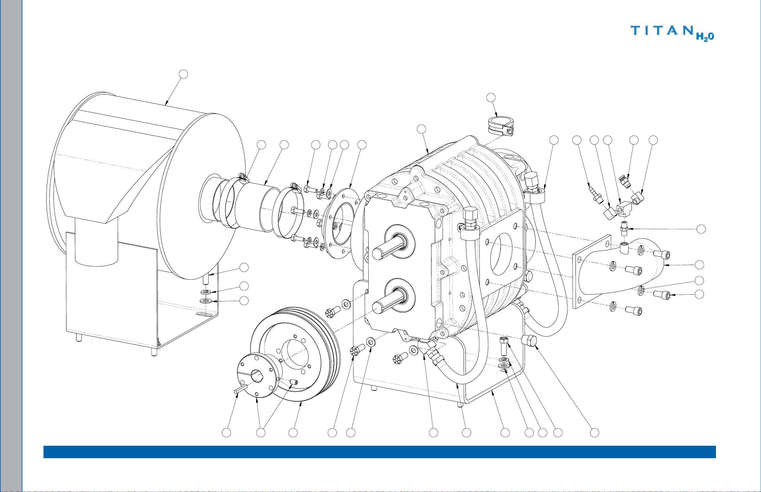
Machine assembly - View 1 of 4Figure 7-1.
Assemblies and Parts lists: 7-2
Page 49
610-050-743
11
Machine assembly - View 2 of 4Figure 7-2.
7-3: Assemblies and Parts lists
Page 50

SOME HOSES AND EXTERNAL PARTS HIDDEN FOR CLARITY
2
8
12
18
13
2 X
16
2 X
15
2 X
17
2 X
Machine assembly - View 3 of 4Figure 7-3.
610-050-743
Assemblies and Parts lists: 7-4
Page 51

610-050-743
SOME HOSES AND EXTERNAL PARTS HIDDEN FOR CLARITY
10
9
3
14
3 X
16
3 X
15
3 X
Machine assembly - View 4 of 4Figure 7-4.
7-5: Assemblies and Parts lists
Page 52

Machine assembly Parts List
Item Part number Description qty
1 610-002-743 Assembly, blower and Silencer 1
2 610-011-743 Assembly, electrical Panel 1
3 610-004-743 Assembly, engine 1
4 610-001-743 Assembly, frame 1
5 610-023-741 Assembly, Side Cover 2
6 610-022-741 Assembly, Top Cover 1
7 610-020-743 Assembly, Upper Dash 1
8 000-041-872 Cover, belt, - Coated 1
9 000-068-919 Hose, 1.75” I.D. X 18.75” lg. flexible 1
Item Part number Description qty
10 000-068-920 Hose, Intake Elbow - Modied 1
11 000-081-327 label, ANSI Warning 3
12 000-094-038 Nut, 5/16”-18UNC Nylock 1
13 000-143-126 Screw, #10-24UNC X 0.50” lg. Hex Head 2
14 000-143-166 Screw, #10-24UNC X 3/8” lg. Hex Head 3
15 000-174-001 Washer, #10 flat 5
16 000-174-014 Washer, #10 lock 5
17 000-174-003 Washer, 1/4” flat 2
18 000-174-004 Washer, 5/16” flat 1
Assemblies and Parts lists: 7-6
Page 53
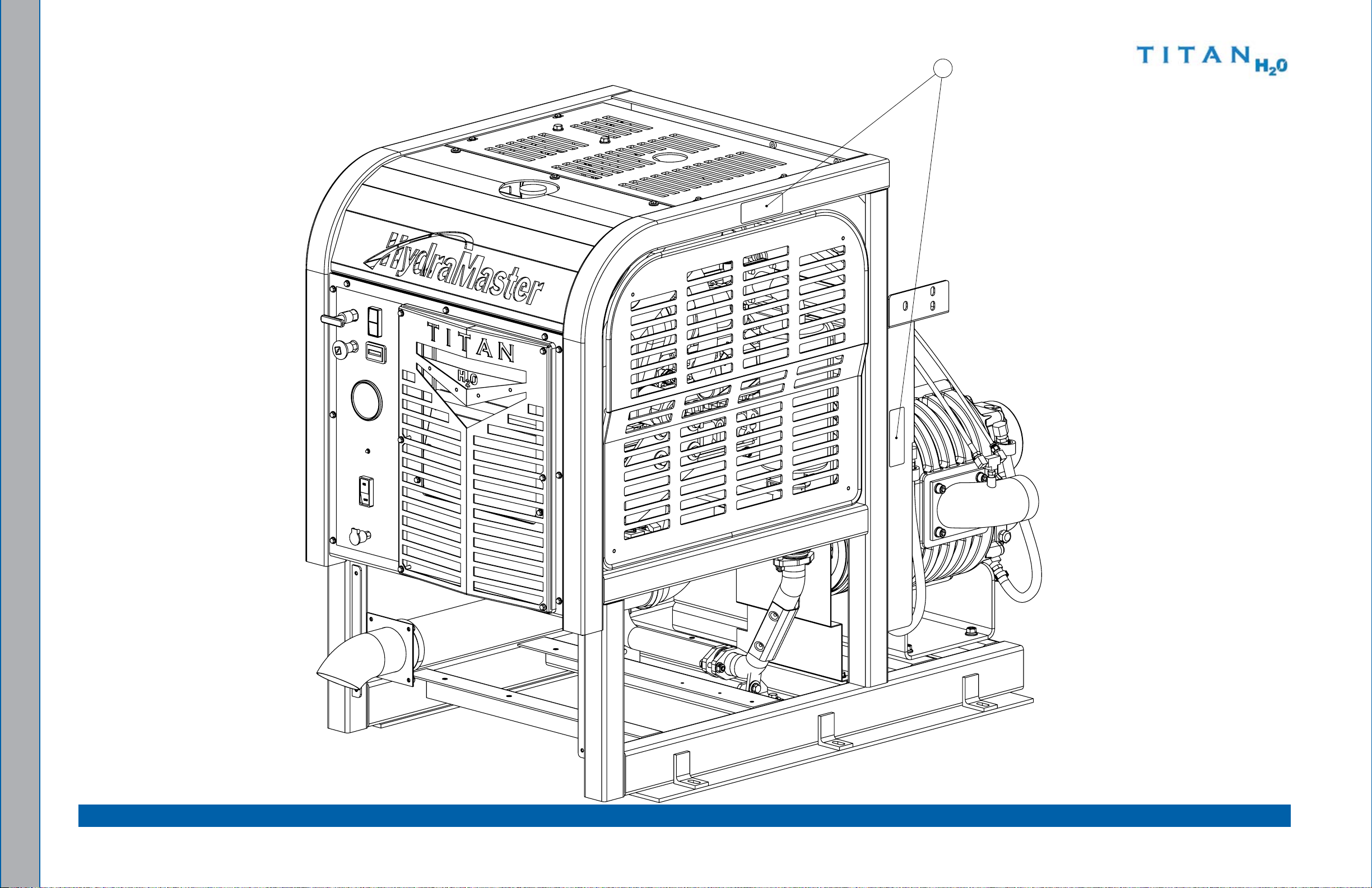
610-001-743
2
8
1
9
2 X
5
4 X
4
7
2 X
13
2 X
12
2 X
6
2 X
11
2 X
10
2 X
3
14
14
15
Frame assemblyFigure 7-5.
7-7: Assemblies and Parts lists
Page 54

Frame assembly Parts List
Item Part number Description qty
1 000-033-135 Clamp, 1-3/4” Cushion loop w/ 7/16” Hole 1
2 000-055-190 frame - Coated 1
3 000-094-012 Nut, 5/16-18”UNC Hex 1
4 000-108-164 Protector, belt Heat Shield 1
5 000-143-114 Screw, #10-24UNC X 0.50” lg. flat Head Phillips 4
6 000-143-126 Screw, #10-24UNC X 0.50” lg. Hex Head 2
7 000-143-333 Screw, 1/4”-20UNC X 0.50” lg. Hex Head 2
8 000-143-012 Screw, 5/16”-18UNC X 3/4” lg. 1
Item Part number Description qty
9 000-154-156 Spacer, Machine Rising 4” X 35” 2
10 000-174-001 Washer, #10 flat 2
11 000-174-014 Washer, #10 lock 2
12 000-174-003 Washer, 1/4” flat 2
13 000-174-019 Washer, 1/4” lock 2
14 000-174-004 Washer, 5/16” flat 2
15 000-174-018 Washer, 5/16” lock 1
Assemblies and Parts lists: 7-8
Page 55

Top Cover assembly Figure 7-6.
1
6
2 X
3
8
7
7 X
11
2 X
9
4 X
5
2
10
3 X
4
610-022-741 Rev. A
Top Cover assembly Parts List
Item Part number Description qty
1 - - - Air Cleaner - Kubota engine (Comes w/ engine) 1
2 000-041-552 Cover, brow - Machine - Coated 1
3 000-041-554 Cover, Top - Machine - Coated 1
Item Part number Description qty
7 000-143-126 Screw, #10-24UNC X 0.50” lg. Hex Head 7
8 000-143-143 Screw, 5/16”-18UNC X 1.00” lg. Hex Head 2
9 000-174-001 Washer, #10 flat 4
4 000-049-063 filter, Replacement - engine Air (Comes w/ engine) 1
5 000-068-916 Hose, Kubota Air Intake - Modied 1
6 000-094-038 Nut, 5/16”-18UNC Nylock 2
10 000-174-060 Washer, 1/4” Rubber backed 3
11 000-174-049 Washer, 5/16” flat 2
7-9: Assemblies and Parts lists
Page 56

Side Cover assembly Figure 7-7.
1
2
4 X
4
3
4 X
610-023-741 Rev. b
Side Cover assembly Parts List
Item Part number Description qty
1 000-041-469 Cover, Side - Machine - Coated 1
2 000-089-003 Magnet 4
3 000-094-034 Nut, #10-24UNC Nylock 4
4 000-131-131 Trimlok, 3/8 X 1/8 Rubber edge Trim 1 ft
Assemblies and Parts lists: 7-10
Page 57
610-004-743
21
9
6728
2 X
29
2 X
22
2 X
22
2 X
29
2 X282 X
2
8
2012
14
25
8 X
18
4
3 X
27
23
5
2 X
24
4 X
31
4 X
30
4 X
COIL, IGNITION
(COMES w/ ENGINE)
WASHER (COMES W/ ENGINE)
8X
GASKET 000-057-232
RADIATOR, KUBOTA
000-113-012
SHAFT, STUB - KUBOTA
HOSE, COOLANT
3
10
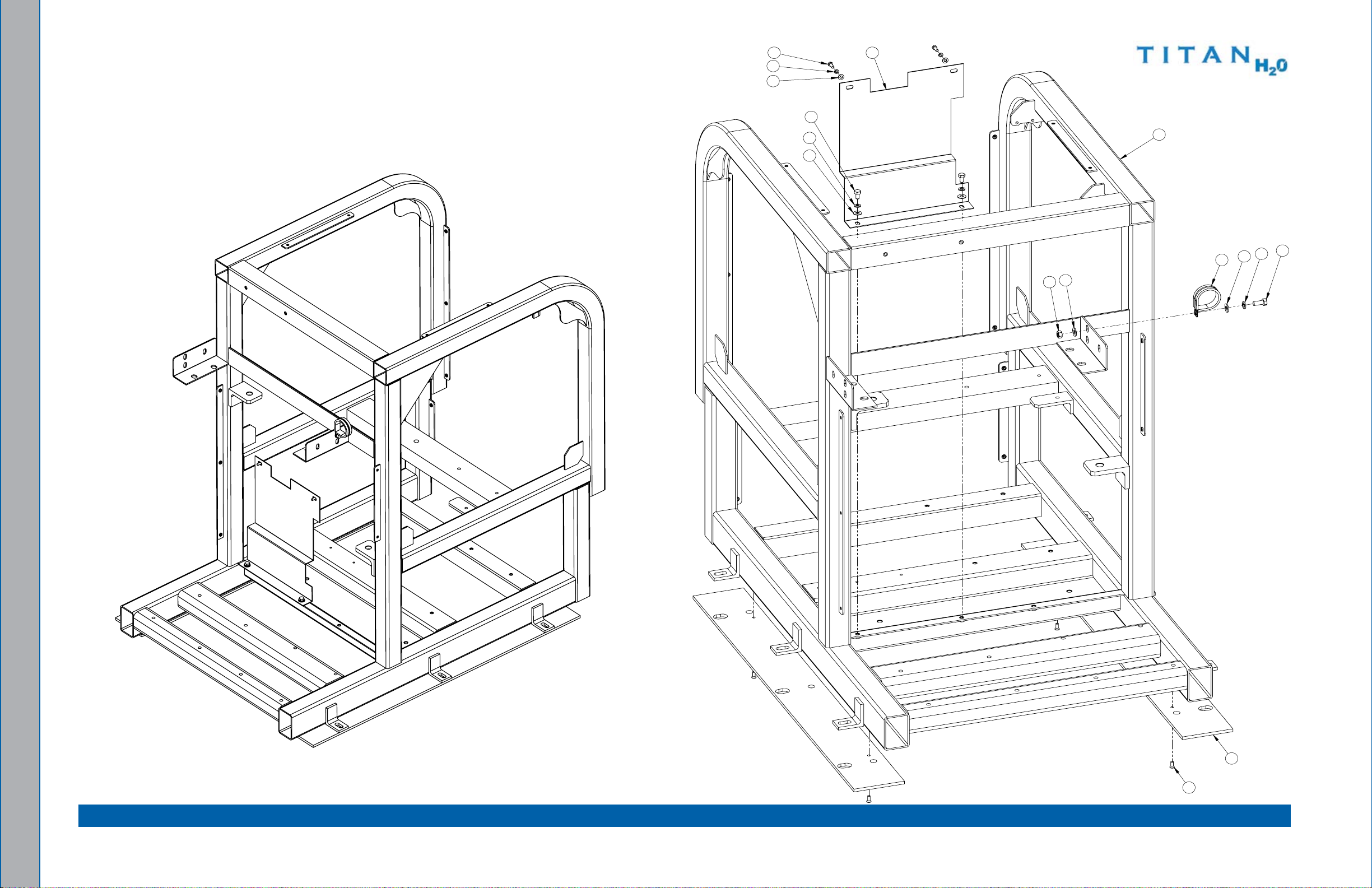
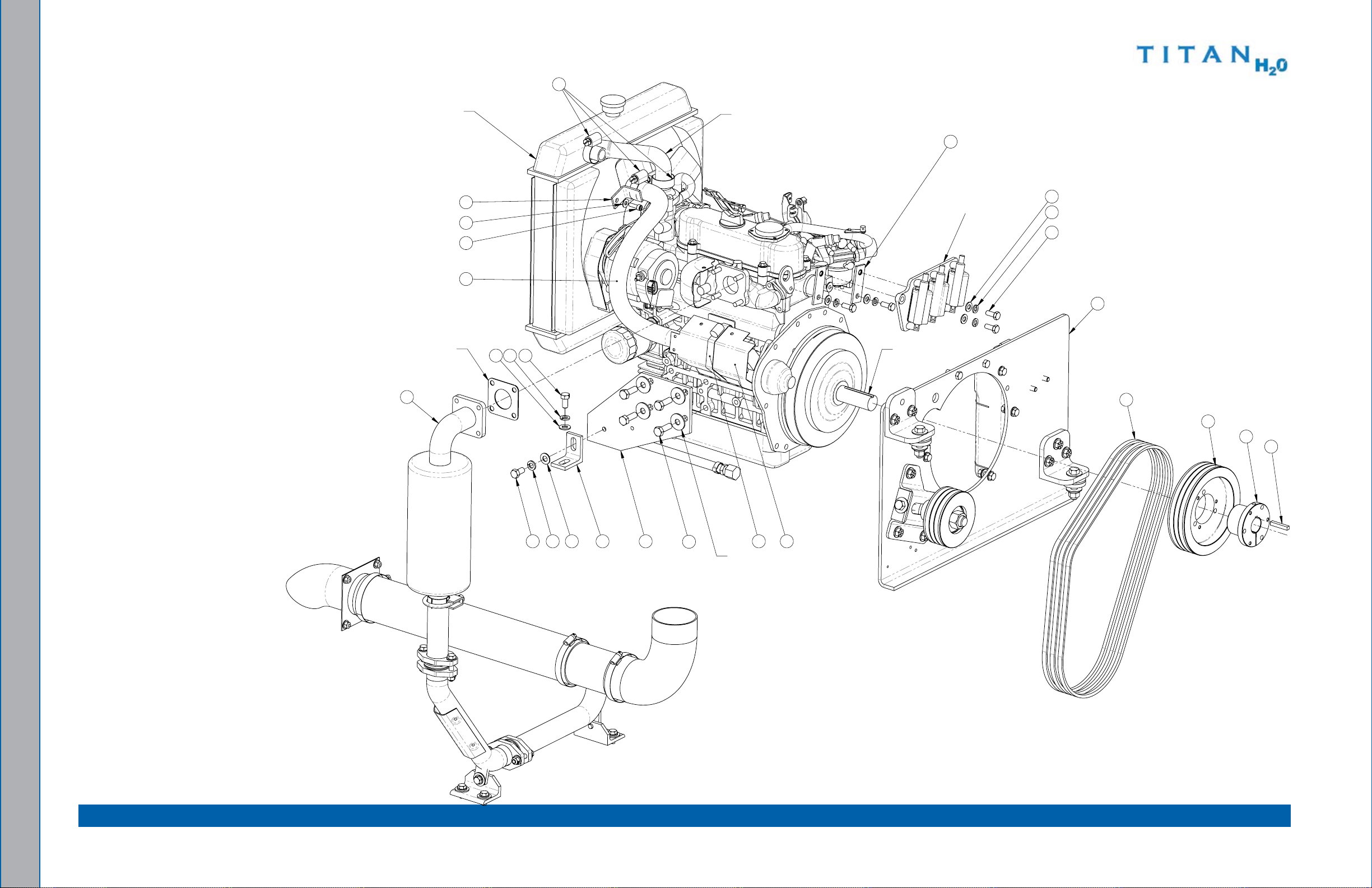
Engine assembly - View 1 of 3Figure 7-8.
7-11: Assemblies and Parts lists
Page 58

610-004-743
13
6
7
16
1
Engine assembly - View 2 of 3 Figure 7-9.
Assemblies and Parts lists: 7-12
Page 59

610-004-743
26
15
11
17
19
Engine assembly - View 3 of 3 Figure 7-10.
7-13: Assemblies and Parts lists
Page 60

Engine assembly Parts List
Item Part number Description qty Item Part number Description qty
1 000-052-906 Adapter, 1/4” f X 12mm Male 1
2 610-013-743 Assembly, exhaust 1
3 610-021-007 Assembly, flywheel Plate 1
4 000-010-131 belt, 3VX450 Super HC 3
5 000-015-1032 bracket, engine, Coil Relocation 2
6 000-015-1052 bracket, engine, front - Coated 2
7 000-015-265 bracket, Machine Tie Down - Coated 2
8 000-015-1167 bracket, Starter Cooling Hose 1
9 000-020-070 bushing, QD SDS Style 1
10 000-033-020 Clamp, Size #16 Hose 3
11 000-033-003 Clamp, Size #4 Mini Hose 1
12 000-033-060 Clamp, Size #80 Hose 1
13 000-047-042 engine, Kubota 32.5HP 1
14 000-068-924 Hose, 1” I.D. Silicone flexible 1
15 000-068-016 Hose, 5/16” I.D. Rubber - bulk 1
16 000-068-221 Hose, Oil Drain 1
17 000-052-109 Insert, #f24 1
18 000-077-010 Key, 1/4” X 1-1/2” lg. Class 2 fit 1
19 000-106-001 Plug, 1/8” NPT 1
20 000-108-165 Protector, Starter 1
21 000-109-124 Pulley, Ø6.5” O.D. Tri-3VX Section 1
22 000-143-017 Screw, 3/8”-16UNC X 0.75” lg. Hex Head Grd. 8 4
23 000-143-077 Screw, 6mm X 20mm lg. Socket Head 1
24 000-143-185 Screw, 8mm X 20mm Gr. 8.8 Hex Head 4
25 000-143-710 Screw, M10 X 1.5 X 30mm lg. 8
26 000-149-545 Sensor, 240°f N/C 1
27 000-174-003 Washer, 1/4” flat 1
28 000-174-005 Washer, 3/8” flat 4
29 000-174-021 Washer, 3/8” lock 4
30 000-174-004 Washer, 5/16” flat 4
31 000-174-018 Washer, 5/16” lock 4
Assemblies and Parts lists: 7-14
Page 61
Blower and Silencer assembly Figure 7-11.
11 23
17
2
5 21
4 X
26
4 X
1118
12
2 X
27
4 X
6 19 14
2 X
27
4 X
22
4 X
4
7
2 X
21
6 X
15
16
10
28
6 X
21
4 X
27
4 X
26
4 X
8
2 X
13 20
6 X256 X246 X
1
3
9
2 X
610-002-743 Rev. A
7-15: Assemblies and Parts lists
Page 62

Blower and Silencer assembly Parts List
Item Part number Description qty Item Part number Description qty
1 000-001-115 Adapter, blower flange to 3” M Slip - Coated 1
2 000-001-041 Adapter, blower Inlet - Coated 1
3 000-093-851 Assembly, Silencer - Coated 1
4 000-111-147 blower, 4007 Dominator 1
5 000-015-976 bracket, blower Mounting - Coated 1
6 000-020-071 bushing, QD SDS Style, 7/8” bore 1
7 000-027-112 Cap, Oil Sight Glass Tuthill blower (Comes w/ blower) 2
8 000-033-013 Clamp, #48 Hose (3”) 2
9 000-033-117 Clamp, 1” Cushion loop w/ 7/16” Mount Hole 2
10 000-033-116 Clamp, 1-1/2” Cushion loop w/ 7/16” Mounting Hole 1
11 000-052-084 elbow, 1/8” NPT Street 2
12 000-052-083 elbow, 3/8” NPT Street X 45° 2
13 000-068-910 Hose, 3.0” I.D. X 3 Ply Silicone X 2” lg. 1
14 000-068-219 Hose, Drain 2
15 000-052-293 Insert, #23 (1/8” NPT X 3/16” barb) 1
16 000-077-011 Key, 3/16” X 1 1/2” long 1
17 000-052-069 Nipple, 1/8” NPT Hex 1
18 000-052-814 Nipple, 1/8” NPT X 1/4” Presto lock 1
19 000-109-124 Pulley, Ø6.5” O.D. Tri-3VX Section 1
20 000-143-001 Screw, 1/4”-20UNC X 0.75” lg. Hex Head 6
21 000-143-018 Screw, 3/8”-16UNC X 1” lg. Hex Head - Grade 8 14
22 000-143-094-1 Screw, 3/8”-16UNC X 3/4” lg. Socket Head 4
23 000-052-092 Tee, 1/8” fPT 1
24 000-174-003 Washer, 1/4” flat 6
25 000-174-019 Washer, 1/4” lock 6
26 000-174-005 Washer, 3/8” flat 8
27 000-174-021 Washer, 3/8” lock 12
28 000-174-049 Washer, 5/16” flat 6
Assemblies and Parts lists: 7-16
Page 63

610-013-743
9
4
5
16
15
20
2 X
12
2 X
13
19
18
6
12
2 X
20
2 X
6
11
2 X
20
2 X
14
3
3 X
8
7
1
17
4 X
10
4 X
13
19
18
20
2 X112 X
13
2 X
19
2 X
18
2 X
13
2 X
19
2 X
18
2 X
2
2
Exhaust assembly Figure 7-12.
7-17: Assemblies and Parts lists
Page 64

Exhaust assembly Parts List
Item Part number Description qty Item Part number Description qty
1 000-001-098 Adapter, exhaust Turndown - Welded 1
2 000-015-393 Bracket, Mufer Support Foot - Coated 2
3 000-033-013 Clamp, #48 Hose (3”) 3
4 000-033-068 Clamp, 1-1/2” exhaust 1
5 000-105-181 flange, Ø1.50” exhaust Donut - Coated 1
6 000-057-199 Gasket, exhaust Donut 2
7 000-068-851 Hose, 3” I.D. X 19” lg. 1
8 000-068-850 Hose, 3” I.D. X 9.5” lg. 1
9 000-093-158 Mufer/Catalytic 1
10 000-094-009 Nut, 1/4”-20UNC Nylock 4
11 000-094-081 Nut, 5/16”-18UNC Hex 2 Way locking 4
12 000-143-124 Screw, 5/16”-18UNC X 1.75” lg. Hex Head 4
13 000-143-012 Screw, 5/16”-18UNC X 3/4” lg. 6
14 000-125-850 Tube, exhaust Diverter - Welded 1
15 000-125-856 Tube, lower engine exhaust - Weldment 1
16 000-125-855 Tube, Ø1.50” O.D. X 0.049” Wall X 5” lg. flare 1
17 000-174-003 Washer, 1/4” flat 4
18 000-174-005 Washer, 3/8” flat 6
19 000-174-004 Washer, 5/16” flat 6
20 000-174-049 Washer, 5/16” flat 8
Assemblies and Parts lists: 7-18
Page 65
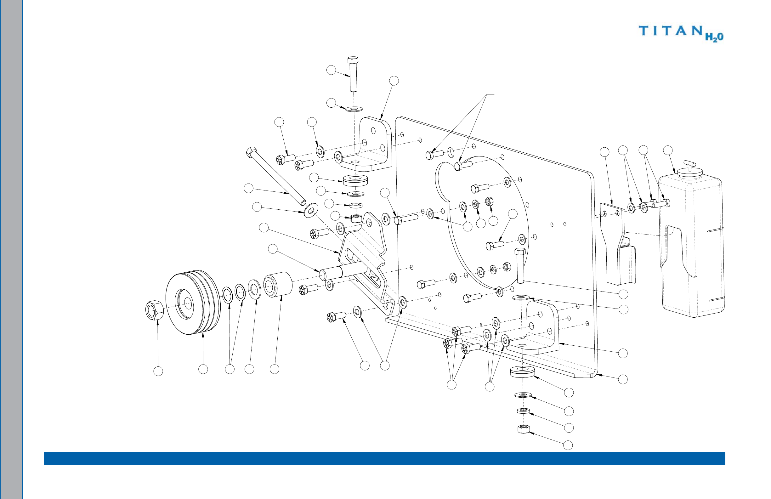
Flywheel Figure 7-13.
12
7
3
15 14
2
11
18
21
21
21
1
8
8
3 X
8
2 X
18
2 X
16
22
5
24
19
23
25
1
13
17
SCREW, 8MM x 1.25 x 25MM LG.
(COMES w/ ENGINE)
6
20
5 X
4
5 X
18
3 X
10
9
4 X
19
5 X
11
21
16
21
22
5
Plate assembly
610-021-007 Rev. b
7-19: Assemblies and Parts lists
Page 66

Flywheel Plate assembly Parts List
Item Part number Description qty Item Part number Description qty
1 000-015-1164 bracket, Angle - Rear engine Mount - Coated 2
2 000-015-941 bracket, Idler Pulley Tensioner - Coated 1
3 000-094-105 Nut, 3/4”-16UNf Hex Zinc Plated 1
4 000-094-120 Nut, 5/16”-18UNC Hex Z/P 5
5 000-094-018 Nut, 7/16”-14UNC Hex Z/P 2
6 000-105-586 Plate, flywheel, Kubota - Coated 1
7 000-109-125 Pulley, Tri Groove 3VX 1
8 000-143-018 Screw, 3/8”-16UNC X 1” lg. Hex Head - Grade 8 8
9 000-143-013 Screw, 5/16”-18UNC X 1.00” lg. Hex Head Grade 8 4
10 000-143-015 Screw, 5/16-18 X 1 1/2” HHC 1
11 000-143-587 Screw, 7/16”-14UNC X 2” lg. Hex Head 2
12 000-143-554 Screw, 7/16-14UNC X 6.5” lg. ft Gr. 5 1
13 000-150-055 Shaft, Idler - Dual V belt 1
14 000-154-195 Spacer, Idler Pulley - 1.403” lg. 1
15 000-174-177 Washer, 0.813 I.D. X 1.125 O.D. X 0.030 Thk. 2
16 000-174-105 Washer, 1-1/16” I.D. Self Aligning Spherical 2 Pc Set 2
17 000-174-027 Washer, 3/4” flat - brass 1
18 000-174-005 Washer, 3/8” flat 11
19 000-174-004 Washer, 5/16” flat 12
20 000-174-018 Washer, 5/16” lock 5
21 000-174-006 Washer, 7/16” flat 5
22 000-174-022 Washer, 7/16” lock 2
23 000-143-143 Screw, 5/16”-18UNC X 1.00” lg. Hex Head 2
24 - - - Bracket, Overow Jug Mounting (Comes w/ Engine) 1
25 - - - Jug, Overow (Comes w/ Engine) 1
Assemblies and Parts lists: 7-20
Page 67
610-020-743
2
9
11
19
1
22
4 X
14
21
3
16
4 X
17
18
7
5
15
9 X
22
9 X
10
22
22
4 X
23
4 X
15
4 X
17
22
Upper Dash assembly- View 1 of 2 Figure 7-14.
7-21: Assemblies and Parts lists
Page 68
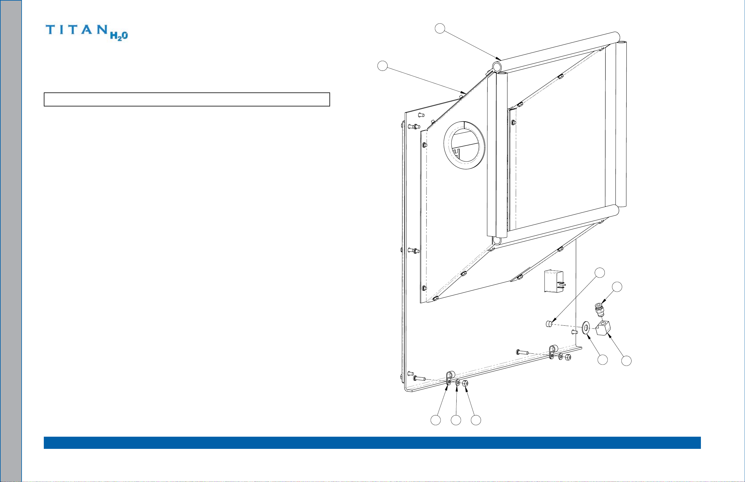
Upper Dash assembly - View 2 of 2Figure 7-15.
4
2 X
22
2 X
13
2 X
8
20
5
24
6
12
610-020-743
Upper Dash assembly Parts List
Item Part number Description qty
1 610-028-743 Assembly, Grill 1
2 000-025-003 Cable, Choke w/ Detent 1
3 000-025-020 Cable, Throttle locking 1
4 000-033-128 Clamp, 3/8” Nylon Hose 2
5 000-052-272 Cup, Gravity feed Oil blower lube Port 1
6 000-052-089 elbow, 1/8” NPT female 1
7 000-074-017 Gauge, 0-30” Hg Vac. 2 1/2” HydraMaster face 1
8 000-042-076 Housing, Radiator Shroud 1
9 000-081-861 label, Upper Dash 1
10 000-084-011 light, Red leD Indicator Mini 1
11 000-074-170 Meter, Rectangular Hour w/o bezel 1
12 000-052-814 Nipple, 1/8” NPT X 1/4” Presto lock 1
13 000-094-034 Nut, #10-24UNC Nylock 2
14 000-100-249 Panel, Upper Dash - Coated 1
15 000-143-126 Screw, #10-24UNC X 0.50” lg. Hex Head 13
16 000-143-171 Screw, #10-24UNC X 1.25” lg. Hex Head 4
17 000-143-065 Screw, #10-24UNC X 1.75” lg. Hex Head 2
18 000-157-040 Switch, 20 Amp Rocker 1
19 000-157-152 Switch, Ignition 1
20 000-131-060 Trimlok, 3/4” bulb X 3/16” Opening 1 ft
21 000-131-131 Trimlok, 3/8 X 1/8 Rubber 1 ft
22 000-174-001 Washer, #10 flat 21
23 000-174-014 Washer, #10 lock 4
24 000-174-032 Washer, 3/8” flat 1
Assemblies and Parts lists: 7-22
Page 69

610-019-743
2
4
4 X
3
4 X
1
Lower Dash assembly Figure 7-16.
Lower Dash assembly Parts List
Item Part number Description qty
1 000-081-328 label, ANSI Warning - large 1
2 000-100-240 Panel, lower Dash - Coated 1
3 000-143-126 Screw, #10-24UNC X 0.50” lg. Hex Head 4
4 000-174-001 Washer, #10 flat 4
7-23: Assemblies and Parts lists
Page 70

grill assembly Figure 7-17.
2
4
3
5
4 X
1
4 X
610-028-743 Rev. A
Assemblies and Parts lists: 7-24
grill assembly Parts List
Item Part number Description qty
1 000-094-058 Nut, #10-32UNf Nylock 4
2 000-100-172 Panel, Grill 1
3 000-100-242 Panel, logo Grill - Coated 1
4 000-131-131 Trimlok, 3/8” X 1/8” Groove 1 ft
5 000-174-001 Washer, #10 flat 8
Page 71

Electrical Panel assembly - Figure 7-18.
16
2 X
8
23
2 X
20
4
View 1 of 2
610-011-743 Rev. A
7-25: Assemblies and Parts lists
Page 72

Electrical Panel assembly - View 2 of 2Figure 7-19.
5
2 X
9
2 X
17
2 X
2
7
21
2 X
17
2 X
13
2 X
3
2 X
6
6
10
2 X
15
2 X
9
2 X
NOTE:
COVER, ITEM #
12
, NOT SHOWN IN THIS VIEW,
19
2 X
11
2 X
12
2 X
24
2 X
18
2 X
22
2 X
22
2 X
14
1
610-011-743 Rev. A
Assemblies and Parts lists: 7-26
Page 73

Electrical Panel assembly Parts List
Item Part number Description qty Item Part number Description qty
1 000-012-002 block, 6 Post Terminal 1
2 000-018-040 Circuit breaker, 50 Amp 1
3 000-037-011 Connector, “Jumper” Terminal Block 2
4 000-041-478 Cover, electrical Panel - Coated 1
5 000-056-006 fuse Holder, In-line - Weatherproof 2
6 000-056-011 fuse, 30 Amp 2
7 000-060-014 Grommet, 1.00” I.D. X 1.50” O.D. 1
8 000-072-018 Ignition Processor, Kubota WG972 1
9 000-094-034 Nut, #10-24UNC Nylock 4
10 000-094-003 Nut, #10-32UNf Hex 2
11 000-094-058 Nut, #10-32UNf Nylock 2
12 000-094-108 Nut, #10-32UNf Wing 2
13 000-094-063 Nut, #6-32UNC Nylock 2
14 000-100-182 Panel, electrical - Universal - Coated 1
15 000-143-533 Screw, #10-24UNC X 0.25” lg. Pan Head Phillips 2
16 000-143-126 Screw, #10-24UNC X 0.50” lg. Hex Head 2
17 000-143-132 Screw, #10-24UNC X 0.75” lg. Hex Head 4
18 000-143-012 Screw, 5/16”-18UNC X 3/4” lg. 2
19 000-156-030 Stud, #10-32UNf X 2” lg. S/S 2
20 000-131-131 Trimlok, 3/8” X 1/8” X 24” lg. Rubber edge Trim 1 ft
21 000-174-001 Washer, #10 flat 2
22 000-174-014 Washer, #10 lock 4
23 000-174-015 Washer, #10 Outside Star 2
24 000-174-049 Washer, 5/16” flat 2
7-27: Assemblies and Parts lists
Page 74

100 gallon Universal Recovery Tank (URT) assemblyFigure 7-20.
17
2X
18
2X
25
4X
33
3X
26
3X
27
2X
15
23
5
28
2X
14
19
7
34
30
16
32
13
2
10
3
29
2X
35
2X
34
2X
6
9
11222124
30
4X
36
4X
19
4X
20
4X
34
4X
12
1
34
4X
30
4X
20
4X
34
4X
12
4
34
4X
30
4X
309X369X19
9X
11
8
37
2X
31
36
610-003-743 Rev. A
Assemblies and Parts lists: 7-28
Page 75

100 gallon Universal Recovery Tank (URT) assembly Parts List
Item Part number Description qty
1 000-001-135 Adapter, Ø3.0 Tank To X 90° blower Hose - Coated 1
2 000-079-091 Assembly, Dura-flow APO - Production 1
3 601-029-701 Assembly, Recovery Tank Cover 1
4 610-026-724 Assembly, Vacuum Relief Valve - URT 1
5 000-012-002 block, 6 Post Terminal 1
6 000-015-932 bracket, flat filter Securing - Uncoated 1
7 000-033-046 Clamp, 1/2 Wide X 1/2 Tube 1
8 000-049-154 Filter, Air Deector, URT - Fabricated 1
9 000-049-153 filter, flat - URT 1
10 000-049-152 filter, Recovery Tank basket 1
11 000-157-091 float, lever Switch 2
12 000-057-206 Gasket, Adapter - URT 2
13 000-052-226 Insert, 1-1/2” NPT X 1-1/2” barb (Grey) 1
14 000-081-554 label, Maintenance and lube Schedule 1
15 000-086-008 latch, bungie 1
Item Part number Description qty
20 000-094-009 Nut, 1/4”-20UNC Nylock 8
21 000-106-019 Plug, 1-1/2” NPT 1
22 000-106-046 Plug, 1-1/4” NPT 1
23 000-106-007 Plug, 1/4” NPT Allen Head 1
24 000-106-049 Plug,1” NPT black Nylon 1
25 000-140-023 Rivet, Ab8-6A Aluminum Pop 4
26 000-143-126 Screw, #10-24UNC X 0.50” lg. Hex Head 3
27 000-143-539 Screw, #6-32UNC X 0.50” lg. button Head 2
28 000-143-051 Screw, #8-32UNC X 3/4” lg. binder Head 2
29 000-143-333 Screw, 1/4”-20UNC X 0.50” lg. Hex Head 2
30 000-143-002 Screw, 1/4”-20UNC X 1.00” lg. Hex Head 22
31 000-159-129 Tank, 100 Gal. Universal Recovery - Coated 1
32 000-169-022 Valve, 1-1/2” full Port ball 1
33 000-174-036 Washer, #10 flat Rubber backed 3
34 000-174-003 Washer, 1/4” flat 19
16 000-052-763 Nipple, 1-1/2” IPS Close S/S 1
17 000-094-063 Nut, #6-32UNC Nylock 2
18 000-094-059 Nut, #8-32UNC Nylock 2
19 000-094-113 Nut, 1/4”-20UNC Neoprene Wellnut 14
35 000-174-019 Washer, 1/4” lock 2
36 000-174-060 Washer, 1/4” Rubber backed 14
37 000-174-029 Washer, 3/8” Rubber backed 2
7-29: Assemblies and Parts lists
Page 76
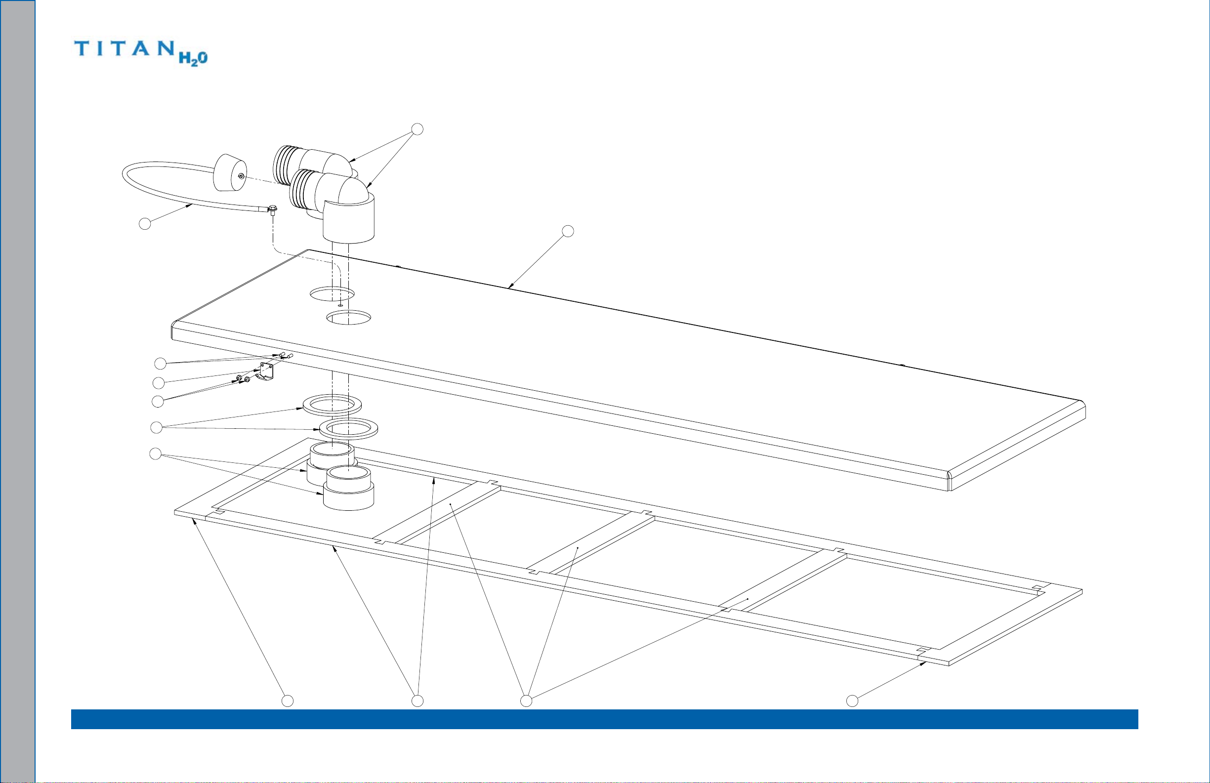
100 gallon Universal Recovery Tank (URT) Cover assemblyFigure 7-21.
10
8
9
5
4
1
75
3
2
11
6
601-029-701 Rev. A
Assemblies and Parts lists: 7-30
Page 77

100 gallon Universal Recovery Tank (URT) Cover assembly Parts List
Item Part number Description qty
1 000-052-219 Adapter, 2” NPT X 2” f Slip 2
2 000-041-447 Cover, 100 Gal. Universal Recovery Tank - Coated 1
3 000-052-222 elbow, 2” barb X 2” fPT 2
4 000-057-015 Gasket, 1-1/2” bulkhead fitting 2
5 000-057-202 Gasket, end - Rec. Tank Cover 2
6 000-057-203 Gasket, Middle - Rec. Tank Cover 3
Item Part number Description qty
7 000-057-205 Gasket, Side - Rec. Tank Cover 2
8 000-078-039 Vacuum Inlet Stopper 1
9 000-086-008 latch, bungee - Strike 1
10 000-094-063 Nut, #6-32UNC Nylock 2
11 000-143-539 Screw, #6-32UNC X 0.50” lg. button Head 2
7-31: Assemblies and Parts lists
Page 78

Vacuum Relief Valve assembly Figure 7-22.
4
7
8
1
5
3
6
2
610-026-724 Rev. b
Vacuum Relief Valve assembly Parts List
Item Part number Description qty Item Part number Description qty
1 000-015-182 bracket, Vacuum Relief Valve - fabricated 1
2 000-027-032 Cap, Spun Vacuum Relief Valve 1
3 000-094-101 Nut, 3/8”-16UNC Hex Jam 1
4 000-094-077 Nut, 3/8”-16UNC X 1.00” O.D. Knurled 2
Assemblies and Parts lists: 7-32
5 000-105-332 Plate, Vacuum Relief Valve Mounting - Coated 1
6 000-143-198 Screw, 3/8”-16UNC X 4” lg. Hex Head - full Thread 1
7 000-155-026 Spring, Vacuum Relief Valve 1
8 000-125-111 Tube, Vacuum Relief Spring Guide 1
Page 79

8 - How to Order Parts
To obtain a proper diagnosis of your malfunction, and to order warranty replacement parts
or repairs, it is important that you proceed in the following manner:
WaRRanTY PaRTS ORDERS
Call the local distributor where you purchased your equipment and ask for the 1.
Service Department.
Have the following information ready:
2.
equipment Model a.
Date of Purchase b.
Hours on the Unit c.
Unit Serial Number d.
Description of Malfunctione.
Once it has been determined which parts are needed to correct the problem with 3.
your machine, make arrangements with your distributor to either perform the repairs
or ship the parts to you.
PaRTS ORDERS
Call your local distributor. In most instances, the distributor either stocks or has access
to parts through a regional service center.
EMERgEnCIES
If, for any reason, your distributor is unable to supply you with the necessary parts, s/he
may call us and arrange for expedited shipping.
HydraMaster sells parts only through authorized distributors and service centers.
8-1: How to Order Parts
Page 80

How to Order Parts: 8-2
Page 81

9 - Warranty Information
To avoid misunderstandings which might occur between machine owners and manufacturer,
we are listing causes of component failure that specically voids warranty coverage. Such
causes as listed below shall constitute abuse or neglect.
BLOWER
failure to lubricate impellers daily with an oil based lubricant. •
failure to lubricate bearings as recommended in blower manual.•
failure to maintain proper oil levels in the blower.•
failure to use the correct oil grade and viscosity as recommended in blower manual. •
Failure to properly maintain blower safeguard systems such as waste tank lter screen, •
vacuum safety relief valve and waste tank automatic shut-off system.
Allowing foam to pass through blower.
•
VaCUUM TanK
Failure to properly maintain ltering devices in tank. •
failure to clean tank as recommended by manufacturer. •
failure to maintain vacuum safety release in tank. •
VaCUUM HOSES
failure to protect hoses against burns from engine and blower exhaust. •
Damage to hoses from being run over by vehicles. •
Kinking or cracking from failure to store or unroll hoses correctly. •
Normal wear and tear from everyday use.•
RECOVERY WanD
Obvious physical abuse of wand.•
gOLDEn gUaRanTEE
Please refer to the following web page for more information concerning HydraMaster’s
warranty policy: http://hydramaster.com/KnowledgeCenter/Warranty.aspx .
A paper copy of the Golden Guarantee is also available in the HydraMaster Titan H2O
documentation package.
9-1: Warranty Information
Page 82

Warranty Information: 9-2
 Loading...