

Page 1
Titan 575
Owner’s Manual
HydraMaster North America, Inc.
11015 47th Avenue West, Mukilteo, Washington 98275
MAN-33165 Rev. 3, March 26, 2010
No part of this manual may be reproduced or used in any form or by any means (i.e. graphic, electronic, photocopying
or electronic retrieval systems) without the express written permission of HydraMaster North America, Inc.
All rights reserved. © 2010 HydraMaster North America, Inc.
(182-575-D)
Page 2

Table of Contents
GENERAL INFORMATION ........................................................................... SECTION 1
System Concept ...................................................................................... 1-3
Contact Information ................................................................................. 1-4
Warnings, Cautions and Notices ............................................................. 1-5
Responsibilities ....................................................................................... 1-9
Machine Specications ........................................................................... 1-12
Optional Equipment................................................................................. 1-14
Spare Parts ............................................................................................. 1-15
High Altitude Operation ........................................................................... 1-17
Local Water Precautions ......................................................................... 1-17
INSTALLATION INFORMATION ................................................................... SECTION 2
Operating the Titan 575 In Hot Weather ................................................. 2-2
Setting up the Titan 575 .......................................................................... 2-5
Orientation of Fuel Pump ........................................................................ 2-6
CLEANING INFORMATION ......................................................................... SECTION 3
Precautions ............................................................................................. 3-2
Preparing the Carpet for Extraction......................................................... 3-2
Rinse and Recover.................................................................................. 3-3
Overwetting ............................................................................................. 3-3
Streaking ................................................................................................. 3-3
Cleaning Tool Tips ................................................................................... 3-4
OPERATING INSTRUCTIONS ..................................................................... SECTION 4
Setting the Temperature .......................................................................... 4-3
Start-up Procedure .................................................................................. 4-4
Setting the Pressure................................................................................ 4-4
Shut Down Procedure ............................................................................. 4-6
MACHINE MAINTENANCE .......................................................................... SECTION 5
Operational Maintenance ........................................................................ 5-2
Overall Machine Maintenance................................................................. 5-4
Engine Maintenance ............................................................................... 5-5
High Pressure Pump Maintenance ......................................................... 5-8
Vacuum System Maintenance ................................................................ 5-17
Descaling Procedure (Required) ............................................................. 5-18
Freeze Guarding ..................................................................................... 5-19
WATER AND CHEMICAL SYSTEM ............................................................. SECTION 6
i - Titan 575 Owner’s Manual
Page 3

ELECTRICAL SYSTEM ................................................................................ SECTION 7
Electrical System Information.................................................................. 7-1
SYSTEMS TROUBLESHOOTING ............................................................... SECTION 8
Heating System ....................................................................................... 8-2
Chemical System .................................................................................... 8-3
Engine ..................................................................................................... 8-4
High Pressure System ............................................................................ 8-7
Vacuum System ...................................................................................... 8-9
ASSEMBLIES AND PARTS LISTS ............................................................... SECTION 9
Machine Assembly Parts List ................................................................. 9-2
Frame Assembly Parts List .................................................................... 9-6
Electrical Panel Assembly Parts List ...................................................... 9-9
Engine Assembly Parts List..................................................................... 9-15
Blower Assembly Parts List ..................................................................... 9-18
Pump and Silencer Assembly Parts List ................................................. 9-19
Pump Assembly Parts List ...................................................................... 9-22
Water Box Assembly Parts List ............................................................... 9-24
Upper Dash Assembly Parts List............................................................. 9-26
Lower Dash Assembly Parts List............................................................. 9-29
Top Cover Assembly Parts List ............................................................... 9-30
Side Cover Assembly Parts List .............................................................. 9-31
Grill Assembly Parts List ......................................................................... 9-32
Blower Heat Exchanger Assembly Parts List .......................................... 9-34
Coolant Heat Exchanger Assembly Parts List......................................... 9-35
Exhaust Assembly Parts List ................................................................... 9-36
Diverter Valve Box Assembly Parts List .................................................. 9-37
By-Pass Valve Assembly Parts List ......................................................... 9-38
3 Way Valve Assembly Parts List ............................................................ 9-39
Flywheel Plate Assembly Parts List ........................................................ 9-41
Actuator Valve Assembly Parts List ......................................................... 9-42
Hi Pressure Manifold Assembly Parts List .............................................. 9-43
70 Gallon Universal Recovery Tank (URT) Assembly Parts List ............. 9-45
100 Gallon Universal Recovery Tank Assembly Parts List ...................... 9-48
70 Gallon Universal Recovery Tank for
85 Gallon Rotomolded Tank Assembly Parts List .............................. 9-52
100 Gallon Universal Recovery Tank for
85 Gallon Rotomolded Tank Assembly Parts List .............................. 9-56
Pump for High Pressure Washing Kit Assembly Parts List ..................... 9-58
High Pressure Washing Kit - Lower Left Dash Assembly Parts List ....... 9-59
Recovery Tank Cover with 2 1/2” Port Kit Assembly Parts List ............... 9-61
Titan 575 Owner’s Manual - ii
Page 4

HOW TO ORDER PARTS ............................................................................ SECTION 10
Warranty Parts Orders ............................................................................ 10-1
Parts Orders ............................................................................................ 10-1
Emergencies ........................................................................................... 10-1
WARRANTY INFORMATION ....................................................................... SECTION 11
Blower .................................................................................................... 11-1
High Pressure Water Pump ................................................................... 11-1
Vacuum Tank .......................................................................................... 11-1
Chemical System .................................................................................... 11-1
Control Panel ......................................................................................... 11-1
Vacuum and Solution Hoses .................................................................. 11-2
Cleaning Wand and Tool ......................................................................... 11-2
Water Heating System ............................................................................ 11-2
Hard Water Deposits ............................................................................... 11-2
Warranty Procedure ................................................................................ 11-2
ACCESSORIES AND CHEMICAL SOLUTIONS .......................................... SECTION 12
iii - Titan 575 Owner’s Manual
Page 5

List of Figures
Figure 1-1. Hard Water Map of Mainland United States ......................................1-18
Figure 2-1. Location of Roof Vents in Vehicle .......................................................2-1
Figure 2-2. Recommended Location of Titan 575 in Van .......................................2-3
Figure 2-3. Install Fuel Pump, Outlet Side Up........................................................2-6
Figure 2-4. Fuel Pump Must Be in Vertical Position ...............................................2-6
Figure 4-1. Titan 575 Upper Dash Assembly .........................................................4-1
Figure 4-2. Titan 575 Lower Dash Assembly .........................................................4-2
Figure 4-3. Heat Selector Valve .............................................................................4-3
Figure 4-4. Thermostat Dial ...................................................................................4-3
Figure 4-5. Throttle Switch .....................................................................................4-3
Figure 4-6. Location of Water Pressure Selector Valve
(Labels Shown as Part of the
High Pressure Washing Kit - P/N 000-079-126) ................................4-4
Figure 4-7. Location of Chemical System Switches ...............................................4-5
Figure 5-1. Remove Valve Cap and Valve Assembly .............................................5-9
Figure 5-2. Inspect Manifold and Old Valves .........................................................5-9
Figure 5-3. Replace Center Inlet Check Valve With Modied Check Valve .........5-10
Figure 5-4. Apply Grease and Install Valves ........................................................5-10
Figure 5-5. Replace Valve Cap and Torque to 95 ft. lbs. (13 m kgs) ....................5-10
Figure 5-6. Separate Manifold from Crankcase ................................................... 5-11
Figure 5-7. Seal Assemblies May Come Off with Manifold .................................. 5-11
Figure 5-8. Examine Ceramic Plungers ...............................................................5-11
Figure 5-9. Remove Stainless Steel Plunger Bolt and Ceramic Plunger .............5-12
Figure 5-10. Install O-ring, Apply Sealant and
Slide Plunger over Plunger Guide ....................................................5-12
Figure 5-11. Extract Retainers and Seals ............................................................5-13
Figure 5-12. Seal Kit and Insertion Tool for Seal Installation ...............................5-14
Figure 5-13. Install Seal Assembly Using O-Ring Grease ...................................5-14
Figure 5-14. Install Retainers into Cavities ..........................................................5-15
Figure 5-15. Press Low Pressure Seal Assembly into Cavity ..............................5-15
Figure 5-16. Re-install Manifold and Torque Fasteners .......................................5-16
Figure 5-17. Torque Sequence in “X” Pattern ......................................................5-16
Figure 5-18. Torque Bolts to 22 ft. lbs (3 m kgs) ..................................................5-16
Figure 5-19. Recirculation Fitting .........................................................................5-18
Titan 575 Owner’s Manual - iv
Page 6

Figure 6-1. Annotated Water, Chemical and
Solution Flow Diagram - View 1 of 3 ..................................................6-3
Figure 6-2. Annotated Water, Chemical and
Solution Flow Diagram - View 2 of 3 ..................................................6-4
Figure 6-3. Annotated Water, Chemical and
Solution Flow Diagram - View 3 of 3 ..................................................6-5
Figure 6-4. Water, Chemical and Solution Flow Diagram - Larger View ................6-6
Figure 6-5. Chemical Flow Diagram - Larger View ................................................6-7
Figure 6-6. Exhaust Flow Diagram.........................................................................6-8
Figure 7-1. ElectricalSchematic .............................................................................7-2
Figure 7-2. Wiring Diagram - View 1 of 3 ...............................................................7-3
Figure 7-3. Wiring Diagram - View 2 of 3 ................................................................7-4
Figure 7-4. Wiring Diagram - View 3 of 3 ...............................................................7-5
Figure 9-1. Machine Assembly ...............................................................................9-2
Figure 9-2. Frame Assembly - View 1 of 3 .............................................................9-3
Figure 9-3. Frame Assembly - View 2 of 3 .............................................................9-4
Figure 9-4. Frame Assembly - View 3 of 3 .............................................................9-5
Figure 9-5. Electrical Panel Assembly - View 1 of 2 ...............................................9-7
Figure 9-6. Electrical Panel Assembly - View 2 of 2 ...............................................9-8
Figure 9-7. Engine Assembly - View 1 of 5 ..........................................................9-10
Figure 9-8. Engine Assembly - View 2 of 5 .......................................................... 9-11
Figure 9-9. Engine Assembly - View 3 of 5 ..........................................................9-12
Figure 9-10. Engine Assembly - View 4 of 5 ........................................................9-13
Figure 9-11. Engine Assembly - View 5 of 5 ........................................................9-14
Figure 9-12. Blower Assembly .............................................................................9-17
Figure 9-13. Pump and Silencer Assembly ..........................................................9-19
Figure 9-14. Pump Assembly - View 1 of 2 ..........................................................9-20
Figure 9-15. Pump Assembly - View 2 of 2 ..........................................................9-21
Figure 9-16. Water Box Assembly ........................................................................9-23
Figure 9-17. Upper Dash Assembly .....................................................................9-25
Figure 9-18. Lower Dash Assembly - View 1 of 2 ................................................9-27
Figure 9-19. Lower Dash Assembly - View 2 of 2 ................................................9-28
v - Titan 575 Owner’s Manual
Page 7

Figure 9-20. Top Cover Assembly ........................................................................9-30
Figure 9-21. Side Cover - Machine Assembly ......................................................9-31
Figure 9-22. Grill Assembly ..................................................................................9-32
Figure 9-23. Blower Heat Exchanger Assembly ..................................................9-33
Figure 9-24. Coolant Heat Exchanger Assembly .................................................9-35
Figure 9-25. Exhaust Assembly ...........................................................................9-36
Figure 9-26. Diverter Valve Assembly ..................................................................9-37
Figure 9-27. By-Pass Valve Assembly .................................................................9-38
Figure 9-28. 3 Way Valve Assembly.....................................................................9-39
Figure 9-29. Flywheel Plate Assembly .................................................................9-40
Figure 9-30. Actuator Valve Assembly .................................................................9-42
Figure 9-31. Hi Pressure Manifold Assembly .......................................................9-43
Figure 9-32. 70 Gallon Universal Recovery Tank (URT) Assembly .....................9-44
Figure 9-33. 100 Gallon Universal Recovery Tank Assembly - View 1 of 2 .........9-46
Figure 9-34. 100 Gallon Universal Recovery Tank Assembly - View 2 of 2 .........9-47
Figure 9-35. 70 Gallon Universal Recovery Tank for
85 Gallon Rotomolded Tank Assembly - View 1 of 3 .......................9-49
Figure 9-36. 70 Gallon Universal Recovery Tank for
85 Gallon Rotomolded Tank Assembly - View 2 of 3 .......................9-50
Figure 9-37. 70 Gallon Universal Recovery Tank for
85 Gallon Rotomolded Tank Assembly - View 3 of 3 .......................9-51
Figure 9-38. 100 Gallon Universal Recovery Tank for
85 Gallon Rotomolded Tank Assembly - View 1 of 3 .......................9-53
Figure 9-39. 100 Gallon Universal Recovery Tank for
85 Gallon Rotomolded Tank Assembly - View 2 of 3 ......................9-54
Figure 9-40. 100 Gallon Universal Recovery Tank for
85 Gallon Rotomolded Tank Assembly - View 3 of 3 .......................9-55
Figure 9-41. High Pressure Washing Kit - Pump Assembly .................................9-57
Figure 9-42. High Pressure Washing Kit - Lower Left Dash Assembly ................9-59
Figure 9-43. Recovery Tank Cover with 2 1/2” Port Kit Assembly .......................9-60
Titan 575 Owner’s Manual - vi
Page 8
1- General Information
The compact but powerful Titan™ 575 is a carefully engineered truckmount carpet
cleaning machine designed and manufactured by HydraMaster North America, Inc. A
950G Daihatsu engine powers the 575’s Tuthill 4007 Tri-Lobe vacuum blower and the
high pressure water pump, rated at 4 gpm (15 litres/minute).
The Titan 575’s innovative design features a blower/engine exhaust diverter which allows
for a non-recirculating or “dump-less” subsystem. This dump-less system, a rst in the
carpet cleaning industry, reduces the need to rell the fresh water tank or empty the
recovery tank.
Other features of the Titan 575 include:
Dual oil bath and sight glasses for enhanced blower reliability•
0 - 1,200 psi (0 - 8,274 kPa) heated for carpet and tile cleaning•
Optional 2,000 psi (13,790 kPa) pressure washing kit•
Dual tool/wand capable•
A.D.C temperature control with instant heat up to 265° F (129.4° C)•
Optional Dura Flow Automatic Pump Out (APO)•
Optional 85 gallon Fresh Water Tank Mounting Kit•
1-1: General Information
Page 9

The Titan 575 can be mounted onto a HydraMaster 85 gallon (322 litre) Rotomolded
Fresh Water Tank. You can also select either the HydraMaster 70 gallon (265 litre)
recovery tank, which comes in the standard equipment package, or a 100 gallon (379
litre) recovery tank, offered as an option.
This Owner’s Manual contains installation and operation instructions as well as information
required for proper maintenance, adjustment and repair of the Titan 575. Component
troubleshooting guides have also been included for your convenience.
It is the purpose of this manual to help you properly understand, maintain and service
your Titan 575. Follow the directions carefully and you will be rewarded with years of
protable, trouble-free operation.
It is imperative that no section of this manual be overlooked when preparing for operation
of the Titan 575. Please read the manual to familiarize yourself with the operation of your
Titan 575, paying special attention to all Warnings and Cautions.
This section of the manual contains the following information:
Contact Information
Warnings, Cautions and Notices
Machine Specications
Responsibilities
Local Water Precautions
General Information: 1-2
Page 10
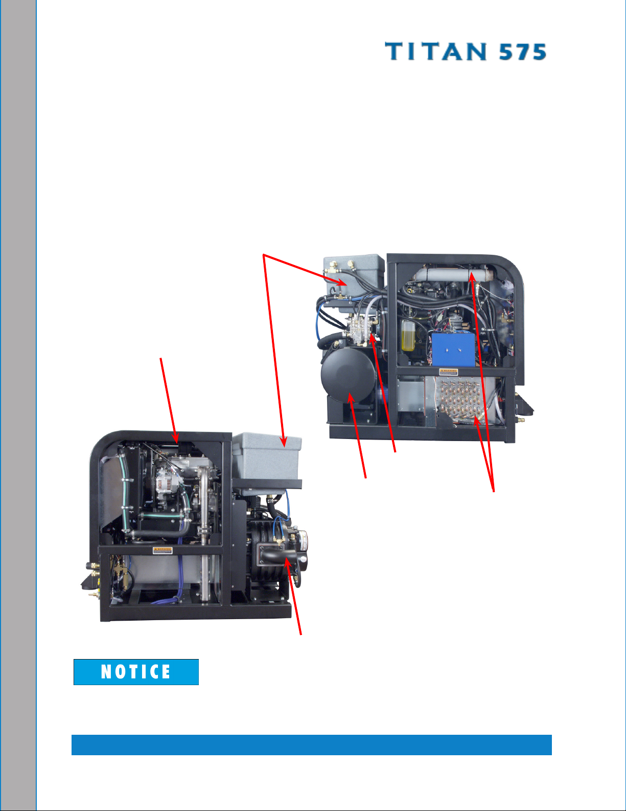
SYSTEM CONCEPT
This is how the Titan 575 works:
Incoming water enters the water box and is pressurized by the high pressure water 1.
pump. The water is heated by engine coolant in the tube and shell heat exchanger
and then by the engine and blower exhaust in the cross ow heat exchanger.
Cleaning solution is then injected into the pressurized water stream and the heated 2.
solution is delivered to the cleaning tool.
The solution is recovered by the vacuum generated by the vacuum pump and is 3.
collected in the recovery tank for proper disposal.
Water Box
Engine
Water Pump
Silencer
Heat
Exchangers
Vacuum Blower
Photographs and illustrations included in this document can represent optional
equipment as well as standard equipment.
1-3: General Information
Page 11
CONTACT INFORMATION
If you have any questions regarding the operation, maintenance or repair of this machine,
please contact your local distributor.
To nd a local distributor, please visit our website at http://www.hydramaster.com/owners/
locate/index.asp.
If your question cannot be resolved by your distributor or by the information within this
manual, you may contact HydraMaster Customer Service direct using the following phone
numbers.
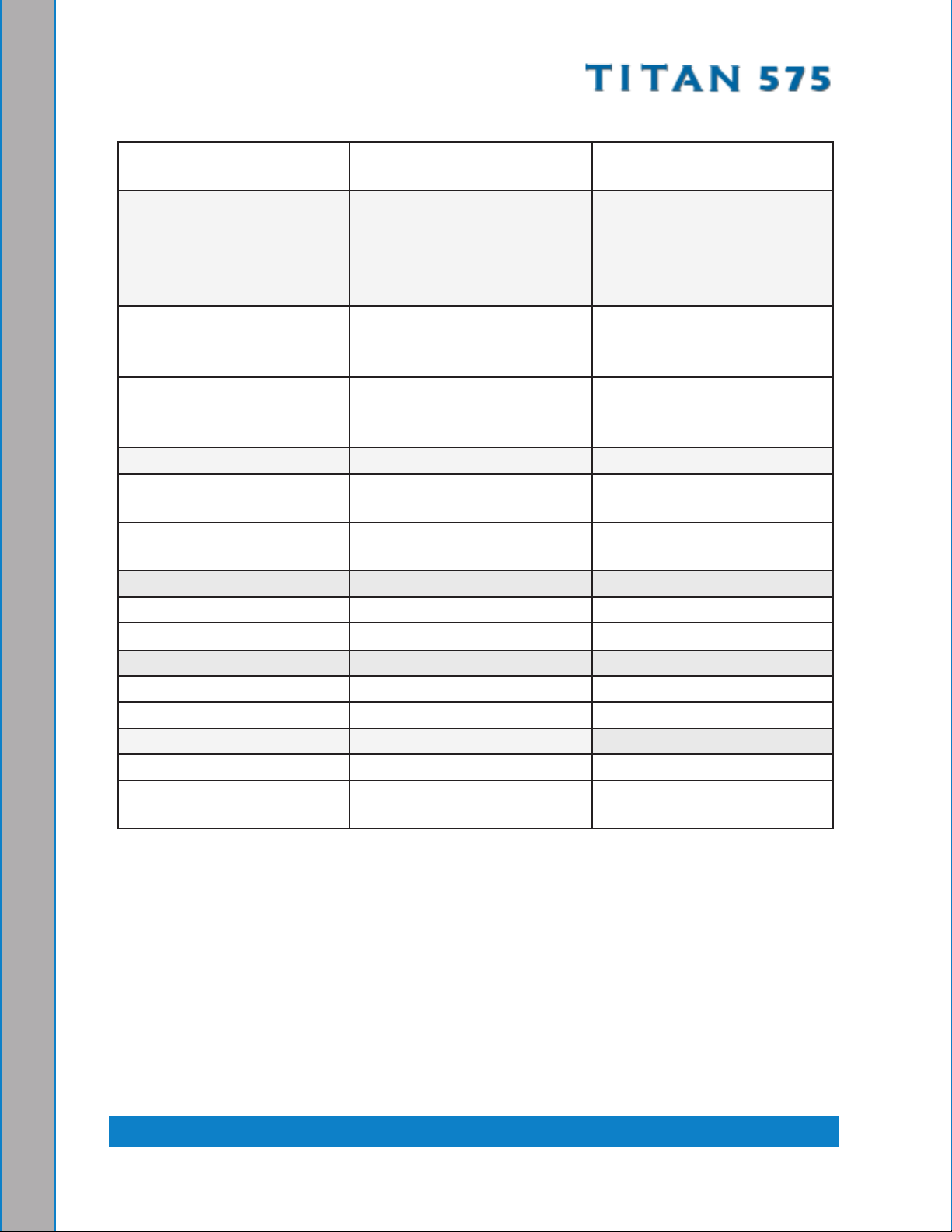
Hours Telephone Numbers E-mail Addresses
Monday-Friday (425) 775-7275 Service
7:00 a.m. to 5:00 p.m. (425) 775-7276 Parts
Pacic Standard Time
(800) 426-4225 Parts /
Service FAX
techsupport@hydramaster.com
Tech Support:
Parts Support:
parts@hydramaster.com
When calling your distributor, be sure to reference the serial number and date of
purchase.
FOR YOUR REFERENCE:
Serial No.____________________________________________________
Date of Purchase:_____________________________________________
Purchased From (Distributor): __________________________________
General Information: 1-4
Page 12
WARNINGS, CAUTIONS AND NOTICES
HydraMaster uses this WARNING symbol throughout the manual to warn of
possible injury or death.
This CAUTION symbol is used to warn of possible equipment damage.
This NOTICE symbol indicates that federal or state regulatory laws may apply,
and also emphasizes supplemental information.
1-5: General Information
Page 13

Warnings and Cautions specic to the Titan 575 include the following:
During the operation of the truckmount many components are in motion. Never
touch any part of the truckmount that is in motion. Serious injury may result.
During the operation of the truckmount many surfaces will become extremely hot.
Never touch hot surfaces. Serious injury may result.
The operation of this truckmount can produce noise levels exceeding 85 decibels
to a distance of 10 ft (3.05 m). The Occupational Safety and Health Administration
(OSHA) recommends the use of hearing protective equipment if a person is
exposed to an average of 85 decibels over an 8-hour period. Check with local
and state agencies concerning hearing conservation rules.
During the operation of the truckmount carbon monoxide and other toxic fumes
are produced. Position the vehicle so that any fumes produced will be directed
away from inhabited areas and any points of building entry (doors, windows, air
conditioning units, fans, etc.). Do not occupy the vehicle while the truckmount is
in operation. Serious injury may result.
During the operation of the truckmount, chemicals known to the State of California
to cause cancer, birth defects and other reproductive harm are produced by the
engine exhaust.
Never operate the truckmount with a portable gas container inside the vehicle.
Doing so will increase the risk of re and explosion. Serious injury or death may
result.
Transporting a vented fuel container that presently contains, or has ever contained
in the past, a ammable liquid is strictly forbidden by HydraMaster and by federal
and state regulations. Doing so will increase the risk of re and explosion. Serious
injury or death may result.
General Information: 1-6
Page 14
Never smoke in or around the truckmount. Doing so will increase the risk of re
and explosion. Serious injury or death may result.
During the operation of the truckmount the exhaust system will become extremely
hot. Keep all ammable materials away from the truckmount exhaust system.
Failure to do so will increase the risk of re and explosion. Serious property
damage may result.
Never operate the truckmount when the vehicle is tilted more than 10 degrees in
any direction. Doing so will result in improper lubrication of the internal components,
and will increase the risk of serious component or engine damage.
Never perform cleaning operations when the truckmount engine is running at the
IDLE throttle position. Failure to do so will increase the risk of serious component
or engine damage.
Never operate the truckmount with the vehicle doors closed. Doing so results in
extremely high temperatures inside the vehicle and will lead to serious component
or engine damage.
Never use concentrated acids or solvents (including d-limonene) in the truckmount
water system or chemical system. Use of these products will cause serious
component damage.
Never operate the truckmount with a water hardness reading measuring 3.0 grains
per gallon (3.79 litres) or higher. Using reading than 3.0 grains per gallon (3.79
litres) will cause scale to build up inside the truckmount water system. Scale build
up causes serious component damage. Test all water prior to use and use water
softening equipment if necessary.
1-7: General Information
Page 15

Never allow water to freeze inside the truckmount. Serious component damage
will occur. Perform all freeze guarding procedures outlined in this digital Owner’s
Manual.
Many vehicles have critical components mounted directly below the oor that
can easily be damaged. Before drilling holes in the oor of the vehicle inspect
the underside of the vehicle for critical components. Failure to do so may result
in damage to the vehicle.
General Information: 1-8
Page 16
RESPONSIBILITIES
Purchaser’s Responsibilities
Prior to purchasing a van, ensure that the payload is suitable for all of the equipment •
that will be installed and transported. This includes and is not limited to: the truckmount,
recovery tanks, fresh water tanks, on-board water, hose reels, hoses, cleaning tools,
chemicals and drying equipment. Payload capacity information is available through
the auto dealer, the manufacturer’s web site, and is also located on the door pillar of
the driver’s side door.
Purchase a heavy duty Group 24 (500+ CC Amps) battery for this truckmount. This is •
normally available from the installation dealer.
Prior to dropping your van off at the distributor for the truckmount to be installed, have •
a spray-on bed liner applied to the oor such as Rhino Lining® or Line-X®.
Plywood and carpet are not recommended.
Prior to operating the truckmount, read this manual in its entirety and familiarize •
yourself with the information contained here. Special attention should be paid to all
Warnings and Cautions.
The distributor is responsible for the correct installation of the truckmount. The •
distributor is also responsible to train you in the correct and proper operation and
maintenance of the truckmount.
Any modication of the truckmount may void the warranty.
1-9: General Information
Page 17

Distributor’s Responsibility
Acceptance of Shipment
Before accepting the truckmount, check the following:
The truckmount should be free from any damage during shipping. Do not sign the 1.
delivery receipt until you have closely inspected the truckmount and noted any
damage on the delivery receipt. Hidden damage may be present even if the box looks
okay. It is recommended that the box be opened before you sign for the shipment.
Check the packing list and verify that all items are accounted for.2.
Installation Responsibilities
Ensure proper payload capacity. It is the distributor’s responsibility to verify that the •
equipment package does not exceed the vehicle capacity.
Ensure installation of a safe fuel tap system and through-oor ttings as provided by •
HydraMaster.
Ensure proper placement of the truckmount, recovery tank, fresh water tank, and •
accessories in the vehicle, and check that they are secured with bolts and back up
plates. The distributor should verify that the owner is in agreement with the layout.
Ensure proper connection of the fuel lines.•
Ensure proper connection and installation of the battery. Verify that the battery is in •
accordance with HydraMaster’s recommendation.
Check the pump, vacuum blower and engine oil levels prior to starting the •
truckmount.
Start and run the truckmount and check that all systems function properly.•
Test all hoses, wands and other accessories for correct operation.•
Ensure timely return of the document package.•
General Information: 1-10
Page 18

Training
The distributor should provide a thorough review of the operation manual with the
purchaser along with instruction and familiarization in:
How all the truckmount’s systems function.1.
All safety precautions and their importance.2.
How to correctly start and shut down the truckmount.3.
How to correctly clean with the truckmount.4.
Where and how often to check and change component oil levels.5.
Freezing damage and how to avoid it. This includes explaining proper freeze 6.
guarding procedures.
How to do basic troubleshooting of the truckmount.7.
Hard water damage and how to avoid it. This includes how to determine if hard 8.
water exists in your area and the installation and use of water softening systems.
The truckmount’s warranty and warranty procedures.9.
1-11: General Information
Page 19
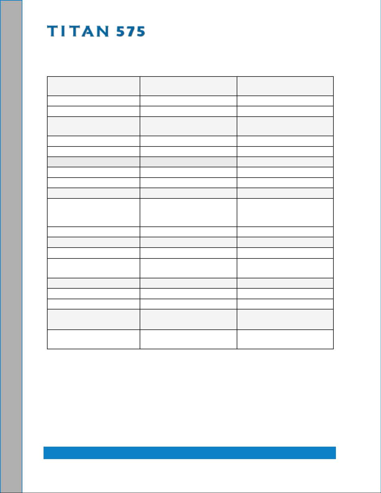
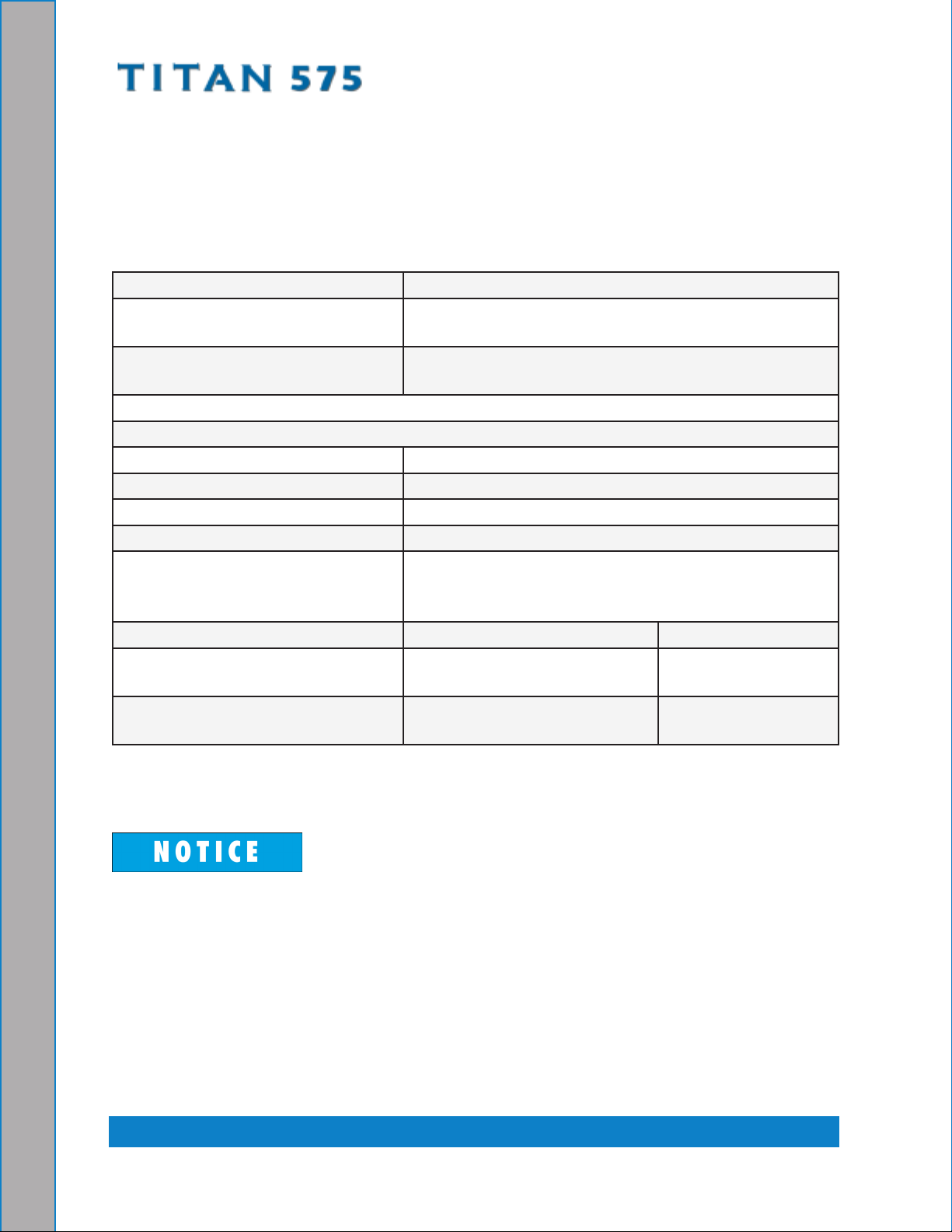
MACHINE SPECIFICATIONS
Frame Dimensions 26.0" W x 45" D x 39" H
(66 cm x 114 cm x 99 cm)
Weight 900 lbs (408 kg)
Engine - Daihatsu 950G Oil Type 5W-30 Synthetic
Capacity 3.2 quarts (3.02 litres)
when changing oil and lter
Engine rpm High - 3,000 rpm
Mid - 2,650 rpm
Idle - 1,500 rpm
Fuel Consumption High - 1.4 gph (5.3 litres/hr)
Mid - 1.2 gph (4.6 litres/hr)
Ignition Keyless
Vacuum Blower - Tuthill
4007 Competitor (Dual
Oil Type
Max. Vac. 12” Hg
PneuLube or other ISO 100
rating
Splash Lubrication)
Gear End Capacity Approx. 5.8 oz. (171.5 ml)
Drive End Capacity Approx. 4.7 oz. (139 ml)
Blower rpm 3,000 rpm
Water Pump- General
Oil Type 15W-40
Pump
Capacity 14 oz (414 ml).
Pump Rate 4.0 gpm (15 litres/minute)
Pump rpm 1,700 rpm
Operating Pressure 0 - 1,200 psi (heated)
(0 - 8,274 kPa)
Chemical System Last Step Chemical
Injection
* Pressure washing option
0 - 2,000 (no heat)
(0 - 13,790 kPa) *
General Information: 1-12
Page 20
Heating System Cross Flow Heat
Exchanger
Standard Equipment High Pressure Solution
Hose
Vacuum Hose 2" Vacuum Hose - 100 ft.
Recovery Hose 10 ft (3.05 m).
Water Box Rotomolded 7 gallon
Recovery Tank 70 gallon Universal Tank
Cleaning Wand/Tool Stainless Steel S-bend
Copper Tube and Shell Heat
Exchanger
1/4" High Temperature
Lined/Vinyl Cover - 100 ft.
(0.635 cm High
Temperature Lined/Vinyl
Cover -30.5 m)
(5.08 cm Vacuum Hose -
30.5 m)
1-1/2" Wand Whip Line -
10 ft. (3.81 cm Wand Whip
Line - 3.05 m)
(26.5 litres) capacity
(265 litre Universal Tank)
Replaceable Grip
Rebuildable Solution Valve
Garden Hose
Chemical Jug 5 gallon (19 litres)
Battery Box
Van Decal
Van Installation Kit
Owner’s Manual (on CD)
Owner’s Guide (printed)
1-13: General Information
Page 21
OPTIONAL EQUIPMENT
To better meet your business needs, HydraMaster offers several options that you can
add to your basic Titan 575 system. The following shows the available options and the
additional kits necessary to install the options. Refer to the following table before placing
your order.
If you want this option: Order this P/N:
2.5” Vacuum Hose Adapter (100
Gallon Recovery Tank Only)
Automatic Pump Out (APO)
without a Fresh Water Tank)
000-078-875 Kit, 2.5” 3 Port Hose and
000-041-466, Cover Assembly
000-079-091 Pump, DuraFlow APO
(70 or 100 Gallon Tank)
For APO options with an 85 Gallon Fresh Water Tank, see * below
Exhaust Through Floor 000-079-127 Exhaust Through Floor Kit
High Pressure Washing 000-079-126 High Pressure Washing Kit
000-079-123 Pressure Washing Gun Kit
* 85 Gallon Fresh Water Tank 000-159-118 85 Gallon Fresh Water Tank
000-079-125 Titan 575 Mounting Kit (includes
“cool air” intake hose) and then order one of these
options:
If you want this option: Order this P/N:
APO w/Standard 70 Gallon
000-079-091
Tank
APO w/Optional 100 Gallon
000-079-094
Tank
If you have questions or need assistance conguring your system, please contact your
distributor.
The Titan 575 comes standard with an exhaust deector to which a hose cannot
connect. HydraMaster strongly recommends you purchase the Exhaust Through
Floor Kit which directs the hot air outside of the van, away from the machine. This
kit is highly recommended for vans with barn doors.
General Information: 1-14
Page 22
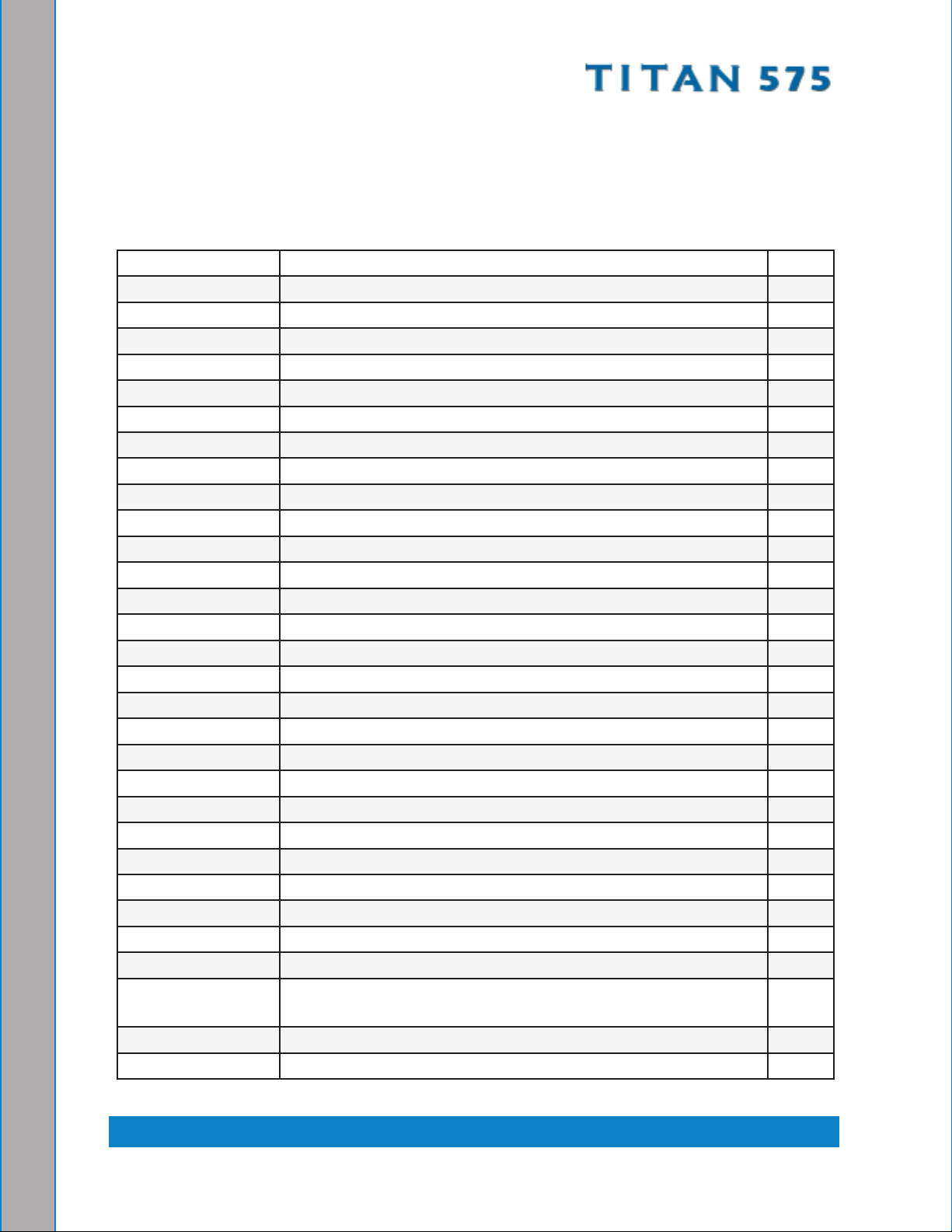
SPARE PARTS
The following table, starting on this page and continuing on the following page, is a list of
available Titan 575 spares that distributors may purchase to have on hand for repairs and
maintenance.
Part No Description Qty
000-010-128 Belt, 9330HD Pump Drive 1
000-010-131 Belt, 3vx450 Eng. Drive 3
000-025-003 Cable, Choke, With Detent 1
000-046-011 Diaphragm, GP 1
000-049-002 Filter, Fuel 1
000-049-014 Filter, Oil - Daihatsu 1
000-049-023 Filter, Garden Hose Screen 1
000-049-063 Filter, Air - Daihatsu 1
000-049-118 Filter, 1/4" NPT Chemical 1
000-049-152 Filter, Basket, Recovery Tank 1
000-049-153 Filter, Stainless Steel Vacuum Pump 1
000-052-050 Quick Connect, 440 Male 3
000-052-051 Quick Connect, 440 Female 2
000-052-052 Quick Connect, 660 Male 1
000-052-053 Quick Connect, 660 Female 1
000-056-011 Fuse, 30 Amp Circuit 2
000-057-177 Gasket, Exhaust Doughnut 1
000-073-011 Impeller, Replacement, APO 1
000-074-025 Gauge, Vacuum 0-30” Hg 1
000-074-032 Meter, Chemical Flow 1
000-074-125 Controller, Temperature 1
000-074-167 Gauge, Pressure 0-3,000 Psi 1
000-078-005 Kit, Bypass Valve Repair 1
000-078-005 Kit, Pressure Regulator Rebuild 1
000-078-019 Kit, H/M Solution Valve 1
000-078-521 Kit, Valve, 4.0 gpm General 1
000-078-522 Kit, Seal, 4.0 gpm General 1
000-087-006 HydraMaster-recommended Lubricant Blower Spray - part
1 ea
number is for 1 can
000-149-039 Sender, Temperature 1
000-149-566 Sensor, Rtd 6" 90˚ 1
1-15: General Information
Page 23
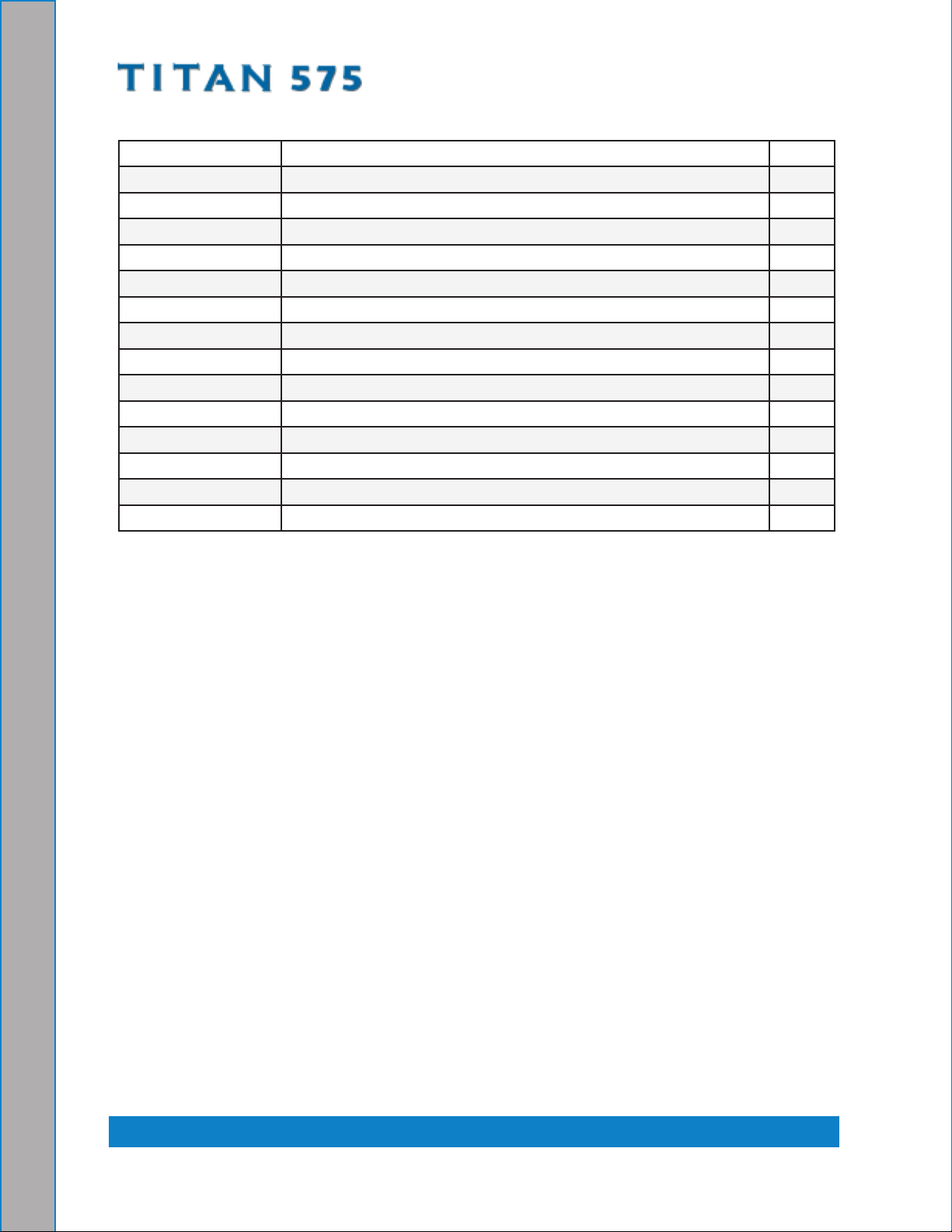
Part No Description Qty
000-157-022 Switch, Relay 2
000-157-040 Switch, 12V DC, On/Off 1
000-157-0801 Switch, Float with Polypropylene Barrel 1
000-157-131 Switch, 12V DC, Throttle 2
000-157-152 Switch, Ignition, 3-Way 1
000-169-011 Valve, Thermal, Low Pressure 1
000-169-0171 Valve, 3-Way (Chemical) 1
000-169-022 Valve, 1 1/2" Full Port 1
000-169-160 Valve, 2-Way (Chemical) 1
000-169-184 Valve, Check, S/S Chemical Pump 2
000-169-213 Valve, 1/4" NPT 3-Way (Heat Selector) 1
000-169-216 Valve, Check, Chemical Pump 1
000-169-218 Valve, Water Box Inlet 1
000-169-219 Valve, Check, Chemical Differential 1
General Information: 1-16
Page 24

HIGH ALTITUDE OPERATION
Elevation plays a key role in how the truckmount will operate. Operation at high altitude
(above 5,000 ft [1,524 m]) may require a high-altitude carburetor jet. Use of this jet at high
altitude will improve power, reduce fuel consumption and help reduce excessive carbon
build-up in the exhaust and heat exchanger systems.
Contact the local Briggs and Stratton dealer or HydraMaster to obtain the proper jet size.
Find your local Briggs and Stratton dealer at http://vanguardengines.via.infonow.net/
locator.
LOCAL WATER PRECAUTIONS
The quality of water varies greatly. Many areas have an excess of minerals in the water
which results in what is commonly called “hard water.” These minerals tend to adhere to
the insides of heater coils and other parts of the machines causing damage and a loss of
cleaning effectiveness. This inuences the reliability and efciency of equipment in direct
proportion to the level of hardness.
Hard Water Advisory
HydraMaster recognizes that any hard water deposits which might occur within the water
system of our truckmounts is a serious problem. The precision technology of truckmount
heat exchanger systems is intolerant of any foreign material. Hard water deposits will
ultimately decrease the performance of the system and are expected to seriously lower
the reliability of the machine.
To validate a machine’s warranty, HydraMaster requires that all machines operating in
designated “Hard Water Areas” (3.0 grains or more per gallon [3.79 litres]) be tted with
a water softening system, or a properly installed magnetic-type descaler must be used
and maintained. Periodic descaling or acid-rinsing alone is not adequate in these areas.
HydraMaster does not recommend any particular type or brand; however, the relative
effectiveness of some types of magnetic descalers or softeners may require additional
periodic use of descaling agents.
HydraMaster also recommends, in the strongest possible terms, that machines in all areas
be tted with a water softening system for improved operation and reliability.
Failure to take appropriate measures to prevent scale build up can result in
system failure and loss of warranty on affected parts.
1-17: General Information
Page 25

Hard Water Area Map
The hard water map, shown in Figure 1-1, denes hard water areas in the continental
United States which compromise uid related components such as hoses, ttings, heaters,
pumps, valves and water-cooled engines. For other countries, hard water area maps can
be obtained from geological societies.
Hard Water Map of Mainland United StatesFigure 1-1.
The map shown in Figure 1-1 is provided for general reference only. Water
hardness in your geographical location should be conrmed by testing.
General Information: 1-18
Page 26

Water Softener
Cleaning efciency and equipment life is increased, chemical use decreased, and the
appearance of cleaned carpets enhanced when water softeners are incorporated in hard
water areas. HydraMaster strongly urges the use of water softener units with the Titan 575
in areas exceeding 3.0 grains per gallon.
Failure to use a water softener in these areas will invalidate the machine’s warranty.
Referring to the hard water area map shown Figure 1-1, determine the quality of water
in your area and take immediate action if the water hardness exceeds 3.0 grains per
gallon.
The relatively low cost of a water softener service is more than made up for by an increased
life of machine parts, reduced chemical costs and continued cleaning efciency. The
water softener will also increase the effectiveness of the cleaning chemicals, therefore
less chemical will be needed.
Contact a water softener distributor in your area for information on the rental of a simple
water treatment unit to carry in your truck. Be sure to charge the water softener in
accordance with the capability of the softener.
For example: If the softener will treat 900 gallons (3,406 litres) of water and the machine
uses an average of 30 gallons/hour (113.5 litres/hour), for an average of 5 hours a day,
this equals 150 gallons per day (568 litres/day). In 6 days the machine would use 900
gallons (3,406 litres) of water. Therefore, the softener would need to be charged every 6
working days for maximum softening.
1-19: General Information
Page 27

Waste Water Disposal Advisory
There are laws in most communities prohibiting the dumping of recovered “gray” water
from carpet cleaning in any place but a sanitary treatment system.
The cleaning rinse water, recovered into your unit’s vacuum tank, contains materials
such as detergents, and must be safely processed before entering streams, rivers and
reservoirs.
In most cases, an acceptable method of waste water disposal is to discharge into a
municipal sewage treatment system after rst ltering out solid material such as carpet
ber. Access to the sanitary system can be obtained through a toilet, laundry drain, RV
dump, etc. Permission should rst be obtained from any concerned party or agency.
One disposal method which usually complies with the law is to accumulate the waste
water and haul it to an appropriate dump site. Another solution to the disposal problem is
to equip your Titan 575 with an Automatic Pump-Out System (APO). These systems are
designed to remove waste water from the extractor’s recovery system and actively pump
the water through hoses to a suitable disposal drain.
HydraMaster makes an APO System which can be ordered with new equipment or
installed later.
When properly congured, the systems will continuously monitor the level of waste water
and pump it out simultaneously with the cleaning operation. The hidden benet of this
process is that the technician does not have to stop his/her cleaning to empty the recovery
tank.
IN ACCORDANCE WITH EPA, STATE AND LOCAL LAWS, DO NOT DISPOSE OF
WASTE WATER INTO GUTTERS, STORM DRAINS, STREAMS, RESERVOIRS,
ETC.
The penalties for non-compliance can be serious. Always check local laws and
regulations to be sure you are in compliance.
General Information: 1-20
Page 28
2 - Installation Information
Although there are many different heavy duty vehicles used for carpet cleaning equipment,
the preferable vehicle for a Titan 575 installation is a cargo van with a heavy-duty
suspension package and a 3/4 HD ton capacity. If a fresh water tank is added, a one ton
or larger capacity van is required.
Prior to installation of the Titan 575, HydraMaster recommends installing a spray-on bed
liner in the vehicle. This provides ‘metal to cushion’ mounting rather than ‘metal to metal’
and makes for an attractive van interior.
HydraMaster also recommends installing roof vents in
vehicles operated in hot weather locations. Roof vent
positions are shown in Figure 2-1. Consult your local RV
distributor about selection and/or installation of powered
roof vents.
For best results, the fan should draw air into the vehicle
which will supply cooler air to the air cleaner intake.
Roof Vents in Vehicle
Location of Figure 2-1.
HydraMaster requires a powered roof vent above the air cleaner intake and a
”cool air intake” hose if the Titan 575 is mounted on an 85 gallon (322 litre) fresh
water tank. Failure to install a powered roof vent in such a manner may result in
serious component or engine damage.
The cool air intake hose is located in the 85 Gallon Fresh Water Tank Mounting
Kit (P/N 079-125).
2-1: Installation Information
Page 29

OPERATING THE TITAN 575 IN HOT WEATHER
HydraMaster recommends the following steps when operating the Titan 575 during periods
of hot weather (95º F [35º C] or higher). This will help ensure that your Titan 575 continues
to run at 100% capacity during even the hottest days.
A minimum of 9” (22.9 cm) of clearance is required on both sides of the Titan 575, 1.
when installed. Ensure that additional equipment or other materials are not stored
at the sides or on top of the Titan. Unobstructed airow around the unit is critical for
cooling the engine and other components.
For side-door vans with “barn doors”, open the doors as wide as their construction 2.
will allow. Be sure to open the doors beyond their standard “straight-out” position,
if possible, by releasing the stops and putting the doors in their fully extended
position.
Provide cross-ventilation. When possible, keeping the rear doors open while the 3.
Titan is running will substantially reduce the temperature inside the van and will
provide a path for cooling air ow. For rear-mount installations, open up the other
doors in the van.
Consider adding powered roof vents to the vehicle (if not already installed). These 4.
vents can signicantly reduce interior temperatures and will result in much cooler
operation. A powered roof vent is required when the Titan 575 is mounted on the
optional 85 Gallon Fresh Water Tank.
Run the Titan 575 in HOT mode when outdoor temperatures are high. Running the 5.
Titan in WARM mode is not “easier” on the machine. In fact, it cuts the coolant heat
exchanger out of the cleaning solution loop, in effect reducing the engine-cooling
capacity. The Titan was designed to deliver solution at the optimum temperature
to clean carpets when in the HOT mode. The WARM mode is intended for delicate
materials like upholstery.
Installation Information: 2-2
Page 30
Use caution when drilling any holes through the van oor. Many vans have critical
components mounted directly below the vehicle oor that could be damaged by
a misplaced drill bit.
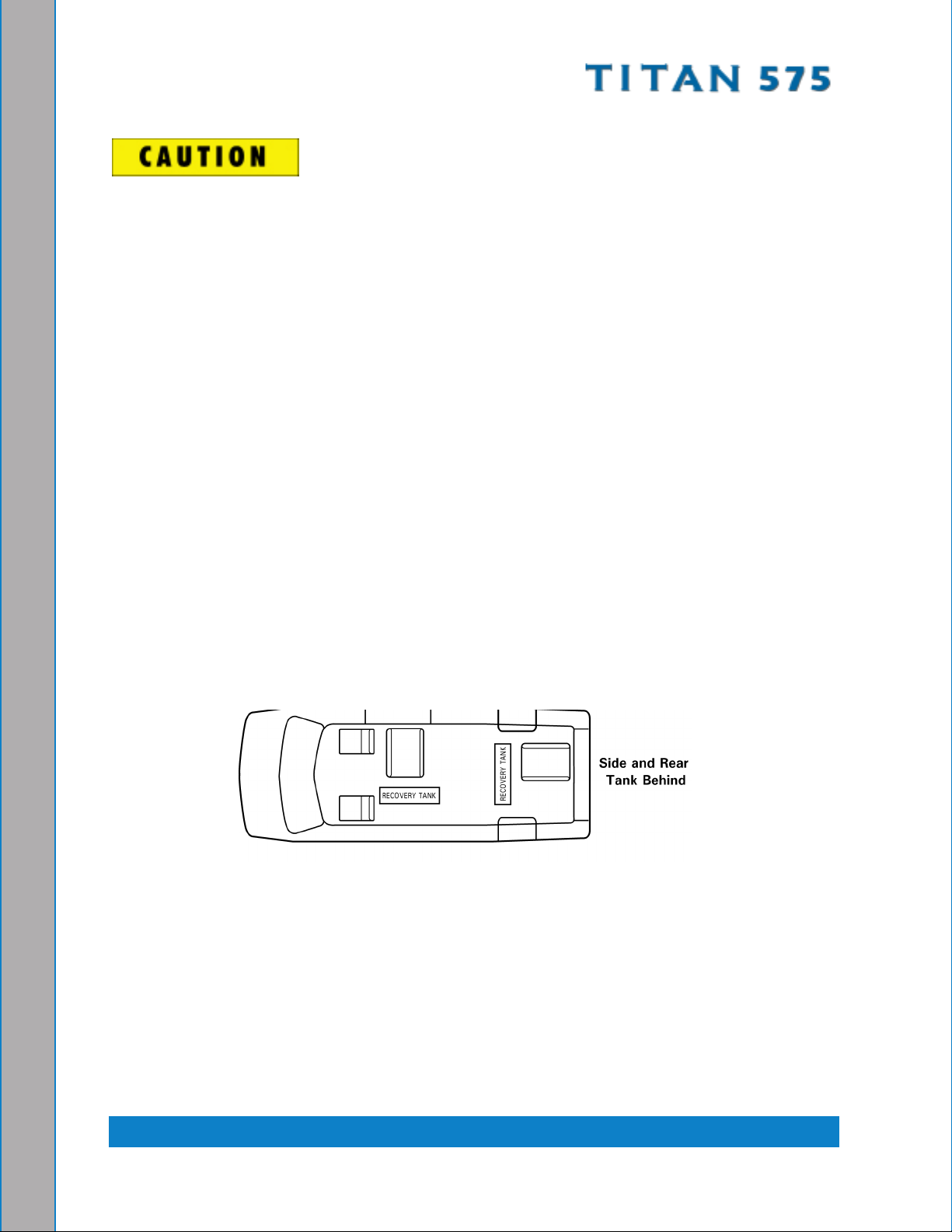
LOCATING THE TITAN 575 IN VEHICLE
There are two recommended entry points on the vehicle for the Titan 575 installation: the
side door or the rear doors.
Most installations are through the side door. This provides rear access for accessories
and hoses as well as unobstructed access to the component/working side of the machine,
thus making it a bit easier to perform maintenance and/or repair without removing the unit
from the truck.
Rear mounting requires the unit to be slid to the right side as far as possible Although
installing the Titan 575 through the rear door partly limits working access, it does direct
the noise away from the cleaning site.
In addition, rear mounting not only provides adequate working space on the component
side of the unit but also improves weight distribution inside the van (engine and component
weight line up over drive shaft). Some cleaners in colder geographical areas prefer this
placement for better traction in ice and snow. Also, it is physically easier to load the unit
into the rear door due to the height of the vehicle bed.
Figure 2-2. Recommended Location of Titan 575 in Van
Secure Installation
No matter how the unit is installed, check to see if the Titan 575 is properly secured to
the oor of the van with the hardware provided. This safety measure will ensure that the
machine will not slide inside the van. See Figure 2-2 for the correct installation.
To install the 85 gallon fresh water tank, follow the procedure outlined in the kit instructions
for P/N 000-079-125.
2-3: Installation Information
Page 31

A sudden or crash stop will cause the machine to rocket forward if not properly
secured. To prevent serious personal injury, ensure that the Titan 575 is well
secured to the oor of the vehicle with the hardware supplied. Protect yourself
and the machine.
HydraMaster strongly recommends that the exhaust from the front of the machine
be vented down under the truck to prevent carbon monoxide from entering the
job site. Always park the truck so the exhaust is blowing away from the job
site.
Never operate this machine with a portable gas can inside the truck. Doing so
increases the risk of a re or explosion.
Mount a re extinguisher just inside the rear or side door for emergencies.
Do not use a portable propane tank inside of the truck or van. It is dangerous and
illegal in most states.
Transporting any vented fuel container that presently holds or has ever held
a ammable liquid in a vehicle containing the Titan 575 is strictly forbidden by
HydraMaster Corporation and by federal and state regulation.
The engine exhaust from this product contains chemicals known to the State of
California to cause cancer, birth defects or other reproductive harm.
Installation Information: 2-4
Page 32

SETTING UP THE TITAN 575
Prior to operating the Titan 575, follow these steps:
Adjust the vacuum relief located on the recovery tank by capping all the vacuum 1.
inlets. The machine should be set to 12” Hg maximum.
Setting the vacuum level higher than the recommended value can result in an
increased risk of serious component damage.
The Titan 575 is shipped from the factory with antifreeze added to the solution system.
Recover this antifreeze and dispose of the recovered antifreeze as stated in the local laws
and regulations.
KEEP ANTIFREEZE OUT OF REACH OF CHILDREN AND ANIMALS. Drinking
antifreeze can cause death.
If required, dispose of antifreeze at facilities licensed to accept household
hazardous waste. If permitted, dispose of antifreeze in sanitary sewer systems.
Do not pour antifreeze into storm sewers, septic systems, or onto the ground.
Doing so causes health and environmental dangers.
Ensure the antifreeze is completely drained from the solution system. If any
antifreeze remains in the system, it could damage machine components and
damage fabric.
2-5: Installation Information
Page 33

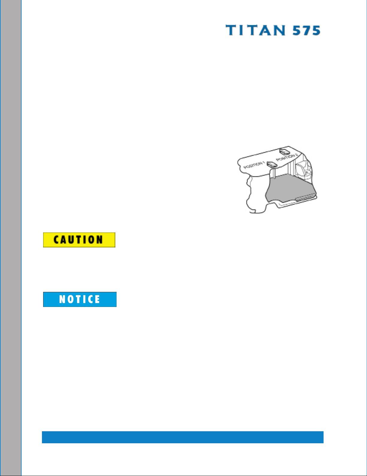
ORIENTATION OF FUEL PUMP
For proper fuel pump operation and fuel ow, the
vehicle’s fuel pump must be installed in a lower
position with respect to the fuel tank and in as
vertical a position as possible (outlet side up - see
Figure 2-3 and Figure 2-4).
Mount the fuel pump away from sources of heat
.
Figure 2-3. Install Fuel Pump,
Outlet Side Up
Figure 2-4. Fuel Pump Must Be in Vertical Position
Installation Information: 2-6
Pump Can Push Fuel
6.5 ft (2 m) Vertically
Page 34

3 - Cleaning Information
The Titan 575 has been engineered using the latest and most sophisticated technology
available to produce the nest carpet cleaning results possible. Despite this, it remains
only a tool of the carpet cleaning trade and can produce only as a good a job as the
person operating it.
HydraMaster strongly recommends attending an Institute of Inspection, Cleaning and
Restoration Certication (IICRC) approved school as soon as possible and to always
follow the IICRC guidelines when cleaning carpets or hard surfaces.
This section describes the carpet cleaning procedure in the following areas:
Precautions
Preparing the Carpet for Extraction
Rinse and Recover
Overwetting
Streaking
Cleaning Tool Tips
3-1: Cleaning Information
Page 35

PRECAUTIONS
The use of some chemicals (such as concentrated acids and/or solvents) in your
truckmount can seriously damage the internal plumbing and high pressure pump.
HydraMaster strongly recommends purchasing a water softener system to prevent the
buildup of scale and hard water deposits in your truckmount.
HydraMaster recommends only the use of chemicals containing rust and corrosion
inhibitors and water softening agents to prevent chemical buildup which may lead to
component failure and warranty invalidation.
Increased demand for a neutralizing rinse results in the need for special care when using
these acid based chemicals in your truckmount The negative side of these products is the
corrosive effects the acid can have on metals, including ttings, pumps, heat exchangers,
etc.
HydraMaster’s ClearWater Rinse™ has been formulated to protect vital components.
HydraMaster will not warranty parts that have been damaged from using acid products
that have obviously caused failures.
PREPARING THE CARPET FOR EXTRACTION
Pre-vacuum the carpet
Whether you instruct the customer to pre-vacuum or you offer it as part of your service,
proper vacuuming will make your job easier with superior end results. The more time
spent removing loose particulate soil, the easier it will be to remove the oily soil stuck to
the bers.
Pretreat the carpet
This process of applying trafc lane type chemicals to the carpet (whether by sprayer or
rotary scrubber) is essential prior to extraction with your truckmount.
By applying cleaning agents to the carpet and letting them dwell 10-20 minutes prior to
rinsing, you allow the product to dissolve and emulsify the oily, sticky binders holding the
soil to the ber. This will allow more soil to be removed in one or two cleaning passes and
help prevent over-wetting.
Remember the solution coming out of your cleaning tool is only in contact with the carpet
ber for a few seconds. Relying on the rinse detergent to do the majority of the cleaning
will result in overly long dry times and excess detergent residue left in the carpet.
HydraMaster recommends the use of our pre-sprays: Fastbreak™ for residential carpet
and Blitz™ for commercial carpet needs.
Cleaning Information: 3-2
Page 36

RINSE AND RECOVER
Whether you are using a wand or an RX-20™, you should clean an area approximately
3 ft. x 3 ft. (92 cm x 92 cm) with the solution valve open then immediately go over that area
with vacuum only to remove any excess moisture.
Olen ber is becoming more popular, particularly in commercial installations. The
process mentioned above can leave excessive residual moisture because olen bers
will not absorb any of the cleaning solution. You must only apply solution during the
backward stroke of the wand so it can be immediately captured by the vacuum head.
RX-20™ users should follow each pass with a dry pass. Failure to follow this procedure
will cause solution to ow to the back of the carpet along with some of the soil. This, along
with any soil imbedded in the backing, will be wicked to the surface of the bers as the
carpet dries.
HydraMaster recommends the following rinse aids: Alkaline - Hydra-Dri Powder™ or
Hydra-Clean™. Acid - ClearWater Rinse™.
OVERWETTING
Overwetting is an annoyance to all concerned. Extended drying times will leave the
customer with a negative impression of both the cleaning company and the process
used.
Several factors that will cause over-wetting include:
Too few vacuum strokes.1.
Clogged vacuum blower lter or vacuum tank lid not sealing properly.2.
Vacuum tank drain valve left partially open.3.
Obstructed, cut or kinked vacuum hoses.4.
Obstructed vacuum hoses while cleaning a heavily foam-saturated carpet (it is 5.
recommended to use a crystal type defoamer distributed evenly over the carpet).
STREAKING
Streaks in the carpet can appear in both clean or dirty areas and normally appear in
heavily soiled, light colored carpets.
Possible reasons of streaking may include:
Clogged or improperly angled spray nozzles.1.
Spray nozzles that overlap, concentrating the solution.2.
A partially clogged vacuum head.3.
Inconsistent solution temperature.4.
3-3: Cleaning Information
Page 37

CLEANING TOOL TIPS
Wands
With a wand, keep cleaning strokes short, front to back, and run a “dry pass”.
After pulling the wand for a strip of 3 or 4 ft (0.9 m or 1.2 m) long with the solution trigger
activated, go back up to the top of the stroke, and make a “dry “ pass [i.e. no solution
owing]. This gives the wand a second chance to pick up the solution on the carpet.
If you do not run a dry pass, the carpet can take longer to dry, and, possibly, the pad under
the carpet can become saturated.
Be aware of the carpet seams; try to use strokes that are parallel with the seam. Avoid
pulling the want across the seam. Every stroke can peel the seam connection and pull
the carpet off the oor.
Also, tilt the wand handle down [head up] to move the tool forward, and away from you,
on the carpet. This means less pull on the carpet and less work for you.
Cleaning Information: 3-4
Page 38

3-5: Cleaning Information
Page 39

Rotary Tool: RX-20
Rotary tools are easier to move on the carpet, but harder to control at rst. With a rotary
tool, remember to keep strokes short and side-to-side.
Before turning on the RX-20, adjust the handle; it should rest right below or even with the
bottom of your pants’ front pockets, with the tool resting at on the oor. Take your time
in adjusting the tool’s height; make sure the head of the tool is at with the oor while you
are holding the handle. Relax your posture; the more difcult it is to hold the tool’s head
at on the oor surface, the more quickly you will tire.
While the tool is running, control the left and right movements of the tool by tilting the head
to the front and back, and lifting the handles up and pushing the handles down. The tool
can be driven to the forward and backward by tilting the head of the unit to the left and
right. The head must be turning to use the self driving feature of the tool, and only requires
a slight bit of pressure to handles to get the head to move the tool across the oor.
As with the wand, drying times will be improved if you run a dry pass between wet passes.
Hold down the solution trigger and move the unit left or right across the oor 3 or 4 ft, then
immediately back across the same pass, without the solution owing, to make the dry
pass. Make the next pass half-overlapping the previous pass.
Use the RX-20 in very heavily trafcked areas or if it has been a long time since the carpet
has been cleaned. Beware of the seam edges of carpets and transition edges between
oor surfaces. Use extreme caution when cleaning these areas.
Sometimes it is necessary to use an edge tool or wand to run the perimeter of the room
on in difcult-to-reach areas where the circular head of the rotary units will not reach.
Cleaning Information: 3-6
Page 40

Upholstery Tool: DriMaster
Use the upholstery tool on small rugs and furniture. When you clean rugs, be sure that the
temperature and chemicals are safe for that particular type of rug.
As with the larger tools, do not leave the surface of the upholstery too wet. Adjust the
volume of water on the tool without it touching any surface: the water should just barely
come out of the tool before the vacuum pulls it back in. The water will only just spray the
top layer of the furniture and the vacuum will pull the dirty water back into the tool.
If you nd it necessary to do a dry pass, keep strokes short to limit the amount of water
that comes into contact with the fabric surface.
3-7: Cleaning Information
Page 41

4 - Operating Instructions
This section describes how to operate the Titan 575, starting with a description of the
dash assembly (see Figure 4-1).
Choke
Pressure
Gauge
MAX VACUUM
12” Hg Decal
Temperature
Gauge
Diverter/Pump
Clutch Switch
Power Switch
(START, RUN and OFF)
MAX VACUUM 12” Hg
Throttle Switch
(HIGH, MID and IDLE)
Vacuum
Gauge
Temperature
Control Dial
Automatic Pump-
Out Switch
Pump-In System
Switch
Figure 4-1. Titan 575 Upper Dash Assembly
The front dash assembly controls the:
System’s power on/off and engine speed•
Pump clutch•
Automatic Pump-Out (APO) if included in the conguration•
Pump-In system if included in the conguration•
The front dash assembly also includes the solution temperature control dial; the
temperature, vacuum and pressure gauges; and the hour meter
4-1: Operating Instructions
Page 42

The lower dash assembly controls the:
Water pressure•
Chemical metering•
Water box drain•
Heat selection for carpet cleaning (HOT) or upholstery cleaning (WARM) - see •
Figure 4-2
Heat Selector Valve (WARM and HOT)
Pressure
Adjustment Regulator
Figure 4-2. Titan 575 Lower Dash Assembly
Chemical Metering
Control System
The lower dash assembly also houses the blower lube port and the two high pressure
cleaning solution port where the wand/tools connect to the Titan 575.
To ensure proper operation of the exhaust diverter system, the Titan 575 must
have a minimum of 10” Hg vacuum. If the vacuum level is lower than 10” Hg, the
exhaust diverter will remain in “Divert” mode.
Photographs and illustrations included in this document can represent optional
equipment as well as standard equipment.
Operating Instructions: 4-2
Page 43

SETTING THE TEMPERATURE
Depending upon the type of cleaning jobs you need to do, there will be times where
you will not need the maximum heat and vacuum
available. There are a few different ways you can
optimize the Titan 575 to the size of the job.
The different scenarios can be dened as follows:
Maximum1. – Dual wands or rotary machine
usage. This means that all available power is
required.
Set the Heat Selector valve to “HOT” - a.
Figure 4-3. Heat Selector Valve
see .
Rotate the thermostat dial to “260” - see b.
Figure 4-4.
Increase engine rpm to “HIGH” - see c.
Figure 4-5.
High Heat/Reduced Vacuum2. – Dual wand with
short hose runs or single wand at longer hose
runs to the job site.
Set the Heat Selector valve to “HOT”.a.
Rotate the thermostat dial to “260”.b.
Increase engine rpm to “MID”.c.
Reduced Heat/Full Vacuum3. – Single wand with
short hose runs to the job site.
Figure 4-4. Thermostat Dial
Set the Heat Selector valve to “WARM”.a.
Rotate the thermostat dial to desired b.
temperature.
Increase engine rpm to “HIGH”.c.
Low Heat/Reduced Vacuum4. – Upholstery or any
reduced solution ow cleaning.
Set the Heat Selector valve to “WARM”.a.
Rotate the thermostat dial to desired b.
temperature.
Increase engine rpm to “MID”.c.
Figure 4-5. Throttle
Switch
Never perform cleaning operations when the
truckmount engine is running at the IDLE throttle
position. To do so will increase the risk of serious component or engine damage.
4-3: Operating Instructions
Page 44

START-UP PROCEDURE
Perform all daily periodic maintenance as specied in this Owner’s Manual.1.
Connect a garden hose to supply water to the truckmount. If the pump-in feature is 2.
used on your system, push the “PUMP-IN” switch to the “ON” position.
Connect the cleaning wand or tool to the length of hose required to perform the 3.
cleaning job.
Start the truckmount with:4.
The throttle switch in the “IDLE” position.a.
The “PUMP CLUTCH” switch in the “OFF” position.b.
After the engine starts, allow the truckmount to run in “IDLE” for 2 - 3 minutes to 5.
warm up.
Never clean when the Titan 575 is in the “IDLE” mode. Failure to follow this
caution may result in serious component or engine damage.
Press the throttle switch to “MID” or “HIGH”.6.
Press the “PUMP CLUTCH” switch to the “PUMP ON HEAT MODE” position for 7.
carpet cleaning or upholstery cleaning; for high pressure washing, press “PUMP ON
NO HEAT”
Set the “HEAT SELECTOR” valve to the 8.
desired position.
Set to the “WARM” position for upholstery a.
cleaning.
Set to the “HOT” position for carpet b.
cleaning.
If the Automatic Pump-Out is included in your 9.
system’s conguration, press the “AUTO
PUMP-OUT” switch to the “ON” position.
SETTING THE PRESSURE
Lower the pressure below 1,200 psi prior to
moving the “WATER PRESSURE SELECTOR”
valve to “CARPET CLEANING” mode (see
Figure 4-6). Failure to do so may result in
serious component or engine damage.
Operating Instructions: 4-4
Location of Water Figure 4-6.
Pressure Selector Valve
(Labels Shown as Part of the
High Pressure Washing Kit -
P/N 000-079-126)
Page 45

Set the cleaning pressure to the desired level as follows.
Carpet Cleaning: 300 to 400 psi1. : Position the “WATER PRESSURE SELECTOR”
valve to “CARPET CLEANING” mode (if equipped). The system is designed to shut
off above 1,200 psi to protect the heat exchanger system (see Figure 4-6).
Hard Surface Cleaning2. : 1,200 psi or as indicated on tool. Position the “WATER
PRESSURE SELECTOR” to “CARPET CLEANING” mode (if equipped). The system
is designed to shut off above 1,200 psi to protect the heat exchanger system.
Pressure Washer Cleaning3. (if equipped): 2,000 psi or as indicated on tool. Position
the “WATER PRESSURE SELECTOR” to “PRESSURE WASHING” mode (if
equipped).
Do NOT apply a vacuum load while using the Titan 575 in “PRESSURE WASHING”
mode. Doing so may cause the machine to overheat.
Turn the “CHEMICAL SYSTEM” switch to the “PRIME” position to purge any air 4.
from the system (see Figure 4-7).
With the truckmount running at “MID” or a.
“HIGH”, block off the vacuum intake to the
recovery tank. The vacuum gauge should
read 12” Hg. This will assist in priming the
chemical system.
Allow the chemical to ow through the b.
chemical meter at full ow for 30 seconds.
Turn the “CHEMICAL SYSTEM” switch to c.
“ON.” The restriction can now be removed
from the vacuum inlet.
While spraying solution from the cleaning d.
tool, adjust the chemical ow by turning
the “CHEMICAL METERING CONTROL”
Figure 4-7. Location of
Chemical System Switches
knob.
Begin cleaning.5.
4-5: Operating Instructions
Page 46

SHUT DOWN PROCEDURE
Flush clean water through the chemical system for 10 seconds. Turn the “CHEMICAL 1.
SELECTION VALVE” to “OFF.”
Cool the truckmount down by turning the “PUMP CLUTCH” switch to “PUMP ON 2.
- NO HEAT”. Spray the cleaning wand into the vacuum hose for 3-5 minutes. The
chemical should now be ushed from the truckmount, hoses and cleaning tool.
Remove the vacuum hose.3.
Lubricate the blower to prevent it from rusting internally.4.
Allow the unit to run for a few minutes with the vacuum hose disconnected in a.
order to remove moisture from the blower.
Cap off the inlet(s) to the vacuum tank.b.
Spray a HydraMaster-recommended spray lubricant into the “BLOWER LUBE c.
PORT” for about 5 to 10 seconds while the unit is running.
Uncap the inlet(s) and run the unit for another minute to allow the blower to cool d.
down.
If freeze guarding is necessary, perform the procedure at this time. See the Freeze 5.
Guarding section of this Owner’s Manual (see page 5-19).
Press the engine throttle switch to the “IDLE” position.6.
Turn the ignition switch to “OFF.”7.
Drain the water box using the valve.8.
Drain the vacuum tank in an appropriate location.9.
In accordance with EPA, state and local laws, do not dispose of water into gutters,
storm drains, streams, or reservoirs.
Perform daily maintenance as specied in Section 10. 5 of this Owner’s Manual.
Operating Instructions: 4-6
Page 47

5 - Machine Maintenance
To avoid costly repairs and downtime, it is imperative to develop and practice good
maintenance procedures. These procedures fall into daily, weekly, monthly and quarterly
increments and are outlined below. All maintenance must be performed by qualied
service personnel.
A maintenance log, provided in the Owner’s Guide, must be correctly and completely lled
out. HydraMaster may request to inspect the logs before a warranty claim is honored.
It is recommended that the log be afxed to the vehicle door near the truckmount for
convenience and to serve as a maintenance reminder.
This section describes how to properly maintain the truckmount in the following areas:
Operational Maintenance
Overall Machine Maintenance
High Pressure Pump Maintenance
Vacuum System Maintenance
Descaling Procedure (Required)
Freeze Guarding
5-1: Machine Maintenance
Page 48

OPERATIONAL MAINTENANCE
Daily Maintenance
Check the engine oil level. Add oil if needed.•
Check the high pressure pump oil. Add oil if needed.•
Check the oil level in the blower. Add oil if needed.•
Check coolant overow bottle level. Add coolant if needed.•
Inspect and clean the recovery tank lters.•
Inspect and clean the garden hose screen.•
Inspect the truckmount for water and oil leaks, loose electrical connections, etc. and •
repair as needed.
Lubricate the blower with a HydraMaster-recommended lubricant. •
Weekly Maintenance
Inspect the recovery tank lters for tears, holes, etc. Repair or replace as needed.•
Inspect the vacuum relief valve. Clean and lubricate as necessary.•
Clean the recovery tank thoroughly with pressure washer.•
Check the pump, drive, blower belt drive, and fan belt for wear and proper tension. •
Adjust as needed.
Check all the hoses and wiring for wear and chang. Secure as needed.•
Flush the water and chemical systems with solution of equal parts white vinegar and •
water.
Check all the nuts and bolts. Tighten as needed.•
One time change of the high pressure pump oil after 50 hours of operation. (Every 500 •
hours thereafter.)
One time change of the engine oil after 25 hours of operation.•
Change the engine oil every 100 hours. (Every 50 hours if operating in high ambient •
temperatures.) Change oil lter every oil change.
Monthly Maintenance
Check the engine air lter. Clean or replace as necessary.•
Check the water level in battery. Fill as needed.•
Clean the battery terminals as needed.•
Machine Maintenance: 5-2
Page 49

Quarterly Maintenance
Check the fuel lines. Repair or replace as needed.•
Clean and gap the spark plugs to 0.031 - 0.035” (0.8 - 0.9 mm). Replace if excessive •
carbon buildup is visible.
Change the blower oil after rst 100 hours of use.•
500 Hours
Change the blower oil.•
Change the high pressure pump oil.•
Check the engine valve clearance (intake and exhaust 0.012” [0.30 mm])•
Replace spark plugs•
Change primary fuel lter•
Change coolant•
1,000 Hours
Replace spark plugs•
Change primary air lter•
Flush coolant system•
5-3: Machine Maintenance
Page 50

OVERALL MACHINE MAINTENANCE
Maintenance, troubleshooting and repair are much easier tasks to accomplish on a clean
truckmount. Regular cleaning of the truckmount offers the user an opportunity to visually
inspect all facets of the truckmount and spot potential problems before they occur. In
addition to the operational maintenance the following “housekeeping” duties should be
performed.
After each job
Check the recovery tank and the recovery tank lters. Empty and clean as •
necessary.
Daily
Wipe the truckmount down thoroughly with a damp cloth. •
Wipe down the vacuum and high pressure hoses as needed.•
Inspect and clean the vacuum slot on the cleaning wand.•
Check the wand head for sharp edges that could tear carpet. File down as needed.•
Clean the wand to maintain original appearance.•
Visually inspect the hoses for abrasions, cuts, etc. Repair or replace as needed.•
Weekly
Empty the chemical container. Wash out thoroughly to remove any chemical buildup.•
Inspect the chemical feed line strainer and use solution of equal parts white vinegar •
and water to remove any chemical buildup.
Thoroughly clean the wand and inspect for clogged jets, debris in vacuum slot and •
leaking ttings at valve.
Thoroughly clean the vacuum and high pressure hoses including quick releases and •
cuffs.
Machine Maintenance: 5-4
Page 51

ENGINE MAINTENANCE
Engine Oil Level Check
The engine oil level should be checked daily. It is recommended that the oil be checked
just before the engine is started for the rst time for that day. The oil level should be
between the ‘Add’ and the ‘Full’ marks on the dipstick.
Do not operate the engine with the oil level below the bottom of the ‘Add’ mark on
the dipstick, or above the top of the ‘Full’ mark.
Adding Engine Oil
It is normal to add some oil in the period of time between oil changes. The amount will
vary with the severity of operation. When adding or replacing engine oil, be sure the oil
meets or exceeds the recommended specication.
Changing Engine Oil and Filter
The engine oil and lter must be changed every 100 hours or every 3 months whichever
occurs rst. The oil and lter should be changed more often if the engine is operating in
dusty or extremely dirty areas, or during cold weather.
Engine Oil Quality
To achieve proper engine performance and durability, it is important that you use only
engine lubricating oils of the correct quality in your engine. Proper quality oils also provide
maximum efciency for crankcase ventilation systems, which reduces pollution.
Use only engine oils displaying the American Petroleum Institute (API) “starburst”
certication mark ‘FOR GASOLINE ENGINES’ on the container.
Engine Oil Recommendation
While multi-viscosity oils are generally recommended, SAE 5W-30 synthetic is specically
recommended year round for your Titan 575 engine.
5-5: Machine Maintenance
Page 52

Oil Filter
Daihatsu engines use a Daihatsu oil lter or a Briggs and Stratton lter. An equivalent or
better oil lter must be used when servicing the engine.
To replace the lter, use a proper lter wrench to remove the lter.
Clean the lter mounting base and lightly coat the gasket surface of the new lter with
engine oil. Hand tighten the lter until the gasket contacts the base, then tighten another
½ turn. Fill the engine with the correct amount of oil, run the engine and check for oil leaks
at the drain plug and oil lter gasket.
Spark Plugs
Always use the recommended spark plugs for your engine. Hotter or colder plugs, or similar
plugs that are not exact equivalents to the recommended plugs, can cause permanent
engine damage, reduce the engines useful life, and cause many other problems such as
hard starting, spark knock and run-on. Installing new spark plugs regularly is one of the
best ways to keep your engine at peak performance.
Cooling System
Coolant Level
Check the coolant level in the coolant overow reservoir daily. Generally a good time to
do this is just prior to starting the engine for the rst time each day.
Maintain the coolant level in the radiator at ¾ “ (19 mm) below the ller neck seat of the
radiator when the coolant is cold. When the coolant level is checked, inspect the condition
of the radiator caps rubber seal. Make sure it is clean and free of any dirt particles which
would keep it from seating on the ller neck seat. Rinse off with clean water if necessary.
Also make sure that the ller neck seat is free of any dirt particles.
Never remove the radiator cap under any condition while the engine is operating.
Failure to follow these instructions could result in damage to the cooling system,
engine, or cause personal injury. DO NOT add coolant to any engine that has
overheated until the engine cools.
The engine manufacture recommends the cooling system to be lled with a 50/50 mixture
of antifreeze and water.
Machine Maintenance: 5-6
Page 53

Always maintain a 50% solution of phosphate-free antifreeze at all times for
adequate heat dissipation, lubrication and protection from freezing. Major brands
are typically low phosphate or phosphate free, and will be labeled accordingly
on the container. It is recommended that you consult the technical data sheet
for the brand of coolant you are using to determine if it meets the low phosphate
requirement. Failure to use a 50% solution of phosphate-free antifreeze may
result in corrosion of the cooling system.
Bleeding Air from Cooling System
It is necessary to remove all of the air from the engine to prevent overheating. If the coolant
has been drained for any reason, it will be necessary to follow the bleed procedure.
When the engine is cold, remove the radiator cap. Fill the radiator until it is to the top of
the ller neck. Start the engine and run in the low rpm position, pump clutch off, and no
vacuum load. Allow the engine coolant to heat up and open the thermostat several times.
As all the air is removed from the system, the level of the radiator should lower below the
internal tubes. This process should take approximately 5 - 10 minutes. Top off the coolant
and install the cap. In the event you experience a coolant shutdown due to overheat,
allow the machine to cool down and repeat this procedure.
Radiator
Inspect the exterior of the radiator for obstructions. Remove all debris with a soft brush or
cloth. Use care to avoid damaging the core ns.
Fuel Filter
The fuel lter is located between the fuel pump and the fuel tank underneath the vehicle.
5-7: Machine Maintenance
Page 54

HIGH PRESSURE PUMP MAINTENANCE
Daily
Check the oil level and the condition of the oil. The oil level should be up to the center of
the sight glass on the side or rear of the pump or between the “MIN” and “MAX” lines on
the dipstick. The dipstick may be found by removing the oil cap.
Periodically
Change the oil after the initial 50 hours of operation and every 500 hours after that. It may
be necessary to replace the pump seals and check valves at 500 hours if the truckmount
has been running in high ambient temperatures.
Refer to the Pump Servicing Section in the following page for more information.
If the oil becomes discolored or contaminated one of the oil seals may be damaged.
Do not operate the pump if the crankcase oil has become contaminated. Do not
rotate the drive shaft without oil in the crankcase reservoir.
The pump should never be run dry. Running the pump dry will cause premature
wear on the seals, packing and plungers. Running the pump dry for a prolonged
period of time may cause damage that cannot be repaired and voids warranty.
Do not run the pump with frozen water in the manifold. If there is a risk of freezing,
freeze guard the truckmount. See the Freeze Guarding section on page 5-19 of
this manual.
Machine Maintenance: 5-8
Page 55

Servicing Valves on the High Pressure Pump
Removing a Valve
Remove the valve cap (30 mm) and extract the valve assembly (see 1. Figure 5-1).
Figure 5-1. Remove Valve Cap and Valve Assembly
Remove the valve assembly (retainer, spring, valve plate, valve seat) from the valve 2.
cavity.
Remove the O-ring and support from the valve cavity.3.
Examine the O-ring and replace if there is any evidence of cuts, abrasion, or 4.
distortion.
Inspect the manifold for wear or damage (see 5. Figure 5-2).
Inspect the old valves for wear or damage. Only one valve kit (P/N 000-078-519) 6.
is necessary to repair all the valves in the pump. (The kit includes new supports,
O-rings, valve seat, valve poppet, spring and retainer; all are pre-assembled.)
Figure 5-2. Inspect Manifold and Old Valves
5-9: Machine Maintenance
Page 56

Replace the center inlet check valve with a modied check valve 7.
(P/N 000-169-212 - Figure 5-3).
Modied Check Valve
Figure 5-3. Replace Center Inlet Check Valve With Modied Check Valve
Apply O-ring grease to O-rings and 8. install valves (Figure 5-4).
Replace valve cap and torque to 95 ft. lbs.(13 m kgs) see 9. Figure 5-5).
Figure 5-4. Apply Grease
and Install Valves
Machine Maintenance: 5-10
Figure 5-5. Replace Valve Cap
and Torque to 95 ft. lbs. (13 m kgs)
Page 57

Remove the fasteners retaining the manifold 10.
Separate manifold from crankcase (see 11. Figure 5-6).
Figure 5-6. Separate Manifold from Crankcase
It may be necessary to rotate crankshaft or tap manifold with rawhide or plastic
mallet to loosen.
When sliding manifold from crankcase, use caution not to damage ceramic
plungers.
The seal assemblies may come off with the manifold (see 12. Figure 5-7)
Figure 5-7. Seal Assemblies May Come Off with Manifold
Examine the ceramic plungers. The surface should be 13.
smooth and free from scoring, pitting or cracks (see
Figure 5-8); if not, replace.
Loosen the stainless steel plunger bolt.14.
Figure 5-8. Examine
Ceramic Plungers
5-11: Machine Maintenance
Page 58

Remove the stainless steel plunger bolt and ceramic plunger from the plunger guide 15.
(see Figure 5-9).
If the slinger washer is removed, be certain it is re-installed or replaced.16.
Separate plunger bolt from ceramic plunger (see 17. Figure 5-9).
Figure 5-9. Remove Stainless Steel Plunger Bolt and Ceramic Plunger
Install new Teon18. ® back-up ring and O-ring on the plunger bolt. Apply a lm of O-ring
grease on the outside of the O-ring (see Figure 5-10).
Apply removable anaerobic thread sealant (Loctite19.
542) to the threads of the plunger
®
bolt, carefully pressing the plunger bolt into ceramic plunger (see Figure 5-10).
Slide new ceramic plunger over the plunger guide (see 20. Figure 5-10).
Figure 5-10. Install O-ring, Apply Sealant and Slide Plunger over Plunger Guide
Torque plunger to 14.5 ft. lbs (2 m kgs).21.
Machine Maintenance: 5-12
Page 59

Extracting Seals
With manifold removed from crankcase:
Insert proper extractor collet through main seal retainer (see 1. Figure 5-11).
Tighten collet and extract retainers and seals.2.
The Teon seals of the HT series will be damaged during disassembly so new
ones with have to be installed.
Figure 5-11. Extract Retainers and Seals
5-13: Machine Maintenance
Page 60

Replacing the Seal Assemblies
Only one seal kit (P/N 078-518) is necessary to repair all the seals in the pump (see
Figure 5-12). Use an insertion tool for seal installation
Figure 5-12. Seal Kit and Insertion Tool for Seal Installation
To install a seal assembly:
Apply a lm of O-ring grease on the O-ring on the outside of the new high pressure seal.1.
Insert the high pressure seal into the cavity with the “U” shape down.2.
Press high pressure seal into place.3.
Apply a lm of grease on the O-ring on the brass retainer (see 4. Figure 5-13).
Figure 5-13. Install Seal Assembly Using O-Ring Grease
Machine Maintenance: 5-14
Page 61

To install the intermediate retainers and the low pressure seals:
Insert the brass intermediate retainer into the cavity.1.
Press the new low pressure seal into the brass low pressure seal retainer and install 2.
a new O-ring on the outside (see Figure 5-14).
Figure 5-14. Install Retainers into Cavities
Press the low pressure seal assembly into the cavity (see 3. Figure 5-15).
Figure 5-15. Press Low Pressure Seal Assembly into Cavity
5-15: Machine Maintenance
Page 62

Re-Installing Manifold
1
3
4
2
5
8
7
6
1
3
4
2
5
8
7
6
Position the outer plungers at the same position (see 1. Figure 5-16).
Re-install manifold and torque the fasteners in an “X” pattern to 50% of specication 2.
and then retorque to 100% specication (see Figure 5-17 and Figure 5-18).
Figure 5-16. Re-install Manifold and Torque Fasteners
Figure 5-17. Torque Sequence
in “X” Pattern
Machine Maintenance: 5-16
Figure 5-18. Torque Bolts to
22 ft. lbs (3 m kgs)
Page 63

VACUUM SYSTEM MAINTENANCE
The vacuum pump in this machine is commonly referred to as a “rotary positive
displacement blower” or “blower” for short. The performance and life of the truckmount is
greatly dependent on the care and proper maintenance it receives. The manual for the
blower has been included. Review the manual for a better understanding of this piece of
machinery.
To protect the blower from overloading and damaging itself, there is a vacuum relief
system installed on the vacuum tank. When the vacuum tank inlet is completely
sealed off a maximum of 12” Hg will be attained.
Solid objects entering the blower will cause serious damage to the internal
components of the blower. Extreme caution should be used when the truckmount is
being run for test purposes with the inlet to the blower open to the atmosphere.
Foam passing through the blower can lead to serious problems with the truckmount.
It is important to keep the vacuum tank free of foam. The tank is protected from
overowing by a oat kill switch; however, this switch is not activated by foam.
Daily
At the end of each day the internal components of the blower need to be lubricated. This
helps to prevent rust deposits and prolongs the life of the truckmount.
To lubricate the blower:
Allow the unit to run for a few minutes with the vacuum hose disconnected in order 1.
to remove moisture from the blower.
Cap off the inlet(s) to the vacuum tank.2.
Spray a HydraMaster-recommended spray lubricant into the “BLOWER LUBE 3.
PORT” for about 5 to 10 seconds while the unit is running.
Uncap the inlet(s) and run the unit for another minute to allow the blower to cool 4.
down.
Periodically
Change the oil in both ends of the blower after the initial 100 hours of use. The oil is to be
changed each 500 hours of use thereafter.
5-17: Machine Maintenance
Page 64

DESCALING PROCEDURE (REQUIRED)
Scale deposits on the interior of the heating system can cause a noticeable loss in
heating performance. Deposits of this kind result from hard water. The frequency with
which descaling procedures are required will vary. If the area has particularly hard water,
you may have to descale often.
To descale the system, add an appropriate descaler chemical to the water box. Circulate
it through the system. Let it stand. Flush and repeat as necessary. Clean all screens and
strainers, and check them frequently following descaling.
If using TM DeScaler™ through the ow meter, make sure to run clean water through the
ow meter after this procedure.
To descale using the recirculation kit (P/N 000-078-058), start with an empty water box.
Fill a third of the water box with TM DeScaler™. Follow the recommendations on the TM
DeScaler™ label for proportions. Verify that the oat is not lying horizontal, but oats
below.
Attach the recirculation tting provided in the kit to the garden hose quick connect (see
Figure 5-19) and this combination to the front of the truckmount.
Attach one section of the solution hose to the outgoing solution tting on the front of the
truckmount and the other end to the garden hose and recirculation tting combination
that is attached to the front of the truckmount. Additional hoses may be attached inline if
descaling of hoses is needed.
Start the truckmount and allow it to run for 3 to 5 minutes. Do not leave the TM DeScaler™
solution in the system. Flush the system with clean water and turn the truckmount
“OFF.”
Figure 5-19. Recirculation Fitting
Machine Maintenance: 5-18
Page 65

FREEZE GUARDING
To avoid permanent damage to the truckmount, it is imperative to follow the Freeze Guard
Procedure whenever the possibility of freezing temperatures exists.
When disposing of antifreeze, follow local laws and regulations. Do not discard
into storm sewers, septic systems or onto the ground.
Antifreeze is harmful or fatal if swallowed. Do not store in open or unlabeled
containers. Keep out of reach of children and animals.
Freeze Guard Procedure
With the truckmount turned off and the incoming water line disconnected, open 1.
the water box drain valve on the front of the truckmount. Allow the system to fully
drain.
Add 2 gallons (7.57 litres) of 50/50 antifreeze and water mix to the water box.2.
Attach a section of solution hose to the outgoing solution tting on the front of the 3.
machine. Attach the opposite end to the recirculation tting. (If more sections of
hose are to be freeze guarded attach those inline.)
Start the truckmount and allow it to run for 2 to 3 minutes. Turn the HEAT SELECTOR 4.
VALVE to “HOT” for 1 minute and then to “WARM” for 1 minute. This will distribute
antifreeze solution throughout the truckmount.
Remove the chemical feed line from the chemical jug. Turn the SELECTOR VALVE 5.
to “PRIME.” This will vacuum the chemical remaining in the lines to the recovery
tank.
When using the recirculation kit, skip ahead to Step 7.
Remove the quick connect tting from the garden hose. Attach the quick connect to 6.
the machine. Using a vacuum hose attached to the recovery tank, vacuum the water
out of the quick connect. This will freeze guard the feed line to the water box.
7. Remove the quick connect from the truckmount.
Spray the antifreeze and water mix out of the truckmount and into a container to 8.
reclaim the solution. Run the solution until it stops.
The truckmount is now freeze guarded. Remember to ush antifreeze from the 9.
system prior to carpet cleaning. See the following procedure.
5-19: Machine Maintenance
Page 66

The reclaimed antifreeze solution may be used three times before being
discarded.
To freeze guard the hoses and wand, perform Step 7 in the preceding procedure
with the items to be freeze guarded attached.
Always check the freezing level of your reclaimed antifreeze with a glycol tester
before reusing. Failure to do so may result in serious component damage.
Recovering Antifreeze for Re-Use
Attach all hoses and wands which have been freeze guarded to the truckmount.1.
Attach the incoming water source to the front of the truckmount.2.
Start the truckmount.3.
Spray the solution through the hoses and wands into a sealable container until all 4.
signs of antifreeze are gone.
Freeze Protection of the Pump-In System
Drain the fresh water tank.1.
Remove the garden hose adapter from the pump-in pump hose and position the 2.
hose so it is pointing outside the van.
Turn on the pump-in pump and run for 1 - 2 minutes until all the water is purged from 3.
the hose.
The next time the truckmount is used, it may take a few minutes before the water
box begins to ll.
Machine Maintenance: 5-20
Page 67

6 - Water and Chemical
System
This section describes the Titan 575’s water and chemical systems, and includes the
exhaust subsystem.
Parts of the text are also included in the section’s annotated illustrations which are
referenced in the following paragraphs (see Figure 6-1 – Figure 6-6).
The process starts when fresh water is brought through the front of the truckmount 1.
into the water box, as indicated in Figure 6-1. The level of water in the box is
maintained by the use of a oat valve. The water is then gravity-fed to the pump
where it is pressurized.
Next, the pressurized water enters the bypass valve. This valve allows manual 2.
adjustment of the pressure level. When the valve at the wand is closed, all the water
in the system is recirculated to the water box. When solution is being used at the
wand, the necessary amount of high pressure water passes through the bypass
valve and to the heat exchanger (see Figure 6-1).
In the tube and shell heat exchanger, the temperature is raised. The heat necessary 3.
to do this is provided by the engine coolant. Heated water then travels to the blower
heat exchanger. In this heat exchanger, the temperature of the water is raised once
again. The heat necessary to do this is provided by both the engine and blower
exhausts (see Figure 6-6). The heated water nally travels to the high pressure
manifold (see Figure 6-1).
The high pressure manifold houses both the temperature sensor for the
temperature gauge and the high temperature shutdown switch. This innovative,
revolutionary system does not require a recirculation orice or lter to maintain
temperature within the heating system.
When water is not owing through the cleaning tool, the water within the heat exchange
system stops circulating completely.
6-1: Water and Chemical Systems
Page 68

Water temperature is controlled via a temperature sensor inside the heat exchanger.
When the system achieves the maximum operating temperature, the diverter valve will
“divert” all heat away from the heat exchanger which allows the system to control its
internal temperature without dumping water.
This saves valuable space in the recovery tank, which can be used instead for recovery
of dirty water from the cleaning surface.
Water that is recirculated through the pressure regulator back to the water box 4.
travels past a thermovalve. This thermovalve monitors the water box temperature.
When the controller senses the water in the water box has reached its set point, it
opens the low pressure thermovalve on the side of the water box and closes once
the temperature drops back below the set point (see Figure 6-2).
The water that is being called for by the wand then exits the manifold and passes 5.
through a check valve (see Figure 6-2).
Finally, the water joins the chemical where the solution is created (see 6. Figure 6-2)
The chemical is pressurized by the HydraMaster diaphragm chemical pump attached 7.
to the head of the water pump. This pump pulls the chemical from the chemical, or
soap, jug through the chemical ow meter (see Figure 6-3).
After being pressurized, the chemical travels through the metering valve and 8.
is injected into the high pressure stream. This solution then exits the front of the
truckmount and is delivered to the cleaning tool (see Figure 6-3).
Water and Chemical System: 6-2
Page 69

Figure 6-1. Annotated Water, Chemical and Solution Flow Diagram - View 1 of 3
7459
1. Fresh water is brought into the water box; water is
gravity fed to the pump where it is pressurized.
2. Pressurized water enters the bypass valve.
3c. Heated water
travels to the high
pressure manifold.
3a. Temperature is raised in the tube and shell heat
exchanger.
3b. Heated water then travels to the blower heat exchanger. In this
heat exchanger, the temperature of the water is raised once again.
6-3: Water and Chemical System
Page 70

Figure 6-2. Annotated Water, Chemical and Solution Flow Diagram - View 2 of 3
7459
5. Water being called for by the wand/tool exits the manifold
and passes through a check valve.
6. The water joins the chemical where the solution is created.
4. Water that is recirculated through the pressure
regulator back to the water box travels past a
thermovalve.
This thermovalve monitors the water box
temperature.
When the controller senses the water in the water
box has reached its set point, it opens the low
pressure thermovalve on the side of the
water box and closes once the temperature drops
back below the set point.
Water and Chemical System: 6-4
Page 71

Figure 6-3. Annotated Water, Chemical and Solution Flow Diagram - View 3 of 3
7459
8. After being pressurized, the chemical travels through the chemical ow
valve and is injected into the high pressure stream. This solution then
exits the front of the truckmount and is delivered to the cleaning tool.
7. Chemical is pressurized by the diaphragm
chemical pump attached to the head of the
water pump. This pump pulls the chemical
from the chemical jug, or soap jug, through
the chemical ow meter.
6-5: Water and Chemical System
Page 72

7459
Water, Chemical and Solution Flow Diagram - Larger ViewFigure 6-4.
Water and Chemical System: 6-6
Page 73

7459
Chemical Flow Diagram - Larger ViewFigure 6-5.
6-7: Water and Chemical System
Page 74

Figure 6-6. Exhaust Flow Diagram
7459
Water and Chemical System: 6-8
Page 75

7 - Electrical System
This section describes how the electrical system functions in the following manner:
Electrical System Information
Electrical Schematic
Wiring Diagram
ELECTRICAL SYSTEM INFORMATION
The Titan 575 electrical system operates on 12 - 14 Volts DC which is provided by the
battery. Battery levels are maintained by a 40-Amp alternator mounted on the engine.
When a new battery is installed, check that it is properly charged before installation
or damage to the charging system may occur.
7-1: Electrical System
Page 76

Schematic
7458 Rev. B
Electrical Figure 7-1.
Electrical System: 7-2
Page 77

View 1 of 3
7457 Rev. B
Wiring Diagram - Figure 7-2.
7-3: Electrical System
Page 78

Wiring Figure 7-3.
Diagram - View 2 of 3
7457 Rev. B
Electrical System: 7-4
Page 79

View 3 of 3
7457 Rev. B
Wiring Diagram - Figure 7-4.
7-5: Electrical System
Page 80

8 - Systems Troubleshooting
This section describes the standard troubleshooting procedures in the following areas:
Heating System
Chemical System
Engine
High Pressure System
Vacuum System
8-1: Systems Troubleshooting
Page 81

HEATING SYSTEM
The truckmount overheats and shuts down1.
1.1. Faulty sensor Inspect the engine overheat switch and test for
functionality.
Unable to achieve normal cleaning solution temperature2.
2.1. Temperature control
knob is turned down.
2.2. The thermovalve is
faulty.
2.3. Excessive solution
ow at tool.
2.4. The heat exchanger
has hard water scale
buildup.
2.5. The heat exchanger
has blockage on the inlet
side.
2.6. The heat selector
valve is in the wrong
position.
Inspect the knob. Adjust if necessary.
Inspect the thermovalve and test for functionality.
The cleaning tool jet is too large or worn. Inspect the jet.
Replace if necessary.
Descale the system.
Inspect the interior of heat exchanger. Remove the debris
and clean as necessary.
Move the heat selector valve to the "HOT" position.
Systems Troubleshooting: 8-2
Page 82

CHEMICAL SYSTEM
System will not prime1.
1.1. The check valves in
chemical pump are faulty.
1.2. The chemical pump
Remove the valves and inspect. Clean or replace as
necessary.
Remove and inspect. Replace as necessary.
diaphragm is faulty.
1.3. The check valve in high
pressure pump is faulty (piston
Remove the valve and inspect. Clean or replace as
necessary.
to which chemical pump is
attached).
1.4. The lter on feed line in
Inspect and clean.
chemical jug is clogged.
1.5. The feed line from
Inspect and repair.
chemical jug is loose, pinched
or damaged.
1.6. The chemical selector
valve is faulty.
Inspect the valve for leaks between ports. Replace as
necessary.
Chemical ow is unstable or low2.
2.1. Air is in the lines Check that all ttings and connections are tight and in
good condition. Repair or replace as necessary.
2.2. The lter screen in the
Inspect and clean.
chemical jug is partially
obstructed.
2.3. The chemical selector
valve is faulty.
2.4. The chemical metering
valve is faulty.
2.5. The high pressure check
valve is faulty.
Inspect the valve for leaks between ports. Replace as
necessary.
Remove and inspect the valve. Clean or replace as
necessary.
Remove and inspect the valve. Clean or replace as
necessary.
Chemical is present in water box3.
3.1. The chemical pump
diaphragm is faulty.
3.2. The high pressure check
valve is faulty.
Remove and inspect the chemical pump diaphragm.
Replace as necessary.
Remove and inspect the valve. Clean or replace as
necessary.
8-3: Systems Troubleshooting
Page 83

ENGINE
The engine will not turn over1.
1.1. A loose or corroded
Clean and tighten the battery terminal connections.
battery terminal.
1.2. The battery is dead. Recharge or replace the battery. Test the charging system.
Repair if necessary.
Do not attempt to jump start the truckmount from
a running vehicle. The amperage output from an
automobile will damage the charging system of the
truckmount.
1.3. The main fuse is
Check the main fuse.
blown.
If the fuse is blown, inspect the electrical system for worn
or shorted wires. Repair or replace as necessary.
1.4. The vacuum blower
has seized.
1.5. The ignition switch is
faulty.
1.6. The starter solenoid
is faulty.
1.7. The starter motor is
faulty.
Attempt to turn the coupler by hand. If it will not turn refer
to the Vacuum System Troubleshooting Subsection.
Test to see if there is power both to and from the switch.
Refer to the Electrical Section of this manual.
Test to see if there is power to solenoid with ignition in
"START" position. Refer to Electrical Section.
Test to see if there is power to the motor with the ignition in
"START" position. Refer to the Electrical Section.
1.8. None of the above. Refer to a qualied service technician for further
troubleshooting.
Systems Troubleshooting: 8-4
Page 84

The engine turns over but will not start.2.
2.1. The recovery tank is
Drain the tank.
full
2.2. The recovery tank
Inspect the oat. Repair or replace as necessary.
oat is faulty.
2.3. The engine ignition
system in faulty.
2.4. Fuel is not reaching
Refer to a qualied service technician for further
troubleshooting.
Test for power to the fuel pump. Refer to Electrical Section.
the carburetor.
If power is present, inspect the fuel pump. Replace if
necessary.
Inspect the fuel lines between the source and the
carburetor. Repair or replace as necessary.
2.5. The engine is
Remove spark plug and dry.
ooded.
2.6. The spark plugs are
Inspect and replace as necessary.
worn or dirty.
2.7. None of the above. Refer to a qualied service technician for further
troubleshooting.
Engine should be adjusted to run at 3,000 rpm under a vacuum load of 12” Hg.
The Engine will not come up to normal operating rpm3.
3.1. Excessive load on
Inspect and clean the recovery tank lters.
the engine.
Inspect the recovery tank to the blower hose. Repair or
replace as necessary.
3.2. Excessive back
pressure on the engine
Inspect for blockage in the heat exchanger. Clean or
replace as necessary.
exhaust.
8-5: Systems Troubleshooting
Page 85

Runs rough at high speed4.
4.1. The spark plug(s)
are faulty.
4.2. The spark plug
wire(s) are faulty.
4.3. Inadequate fuel
supply to the carburetor.
4.4. Poor connection to
coils.
Remove and inspect the plugs. Clean or replace as
necessary.
Inspect the wires and connectors for damage or loose
connections. Repair or replace as necessary.
Check for blockage in the lter. Repair or replace as
necessary.
Verify there is a good contact with each of the wires to the
coils.
Runs rich (black smoke)5.
5.1. A dirty air lter Inspect and replace as necessary.
5.2. Excessive back
pressure
Inspect for a clogged heat exchanger, dirty air lter or a
partially opened choke.
Engine overheats 6.
6.1. Poor ventilation in
Open all the van doors.
the van
Install a roof vent in the van.
Remove any dividers or other objects impeding airow
around the truckmount.
6.2. Low oil level Check the level and ll as necessary.
6.3. Excessive back
pressure on the engine
Inspect for blockage in the heat exchanger. Clean or
replace as necessary.
exhaust
6.4. Low coolant Check radiator level
Check overow bottle level
6.5. Poor coolant mixture Check the coolant with a test to determine mixture; adjust
as necessary.
Systems Troubleshooting: 8-6
Page 86

HIGH PRESSURE SYSTEM
The pump will not come up to normal cleaning pressure1.
1.1. The pressure
Inspect the valve. Repair or replace if necessary.
adjusting valve is faulty.
1.2. Worn seals or valves
in the pump.
Test the pump output volume directly from the pump
at normal running rpm. If the volume is below the
manufacturer's specications, replace the seals and inspect
for defective valves.
1.3. The pump rpm is too
low.
Check for a loose pump belt. Adjust or replace as
necessary.
Check the engine rpm and adjust as necessary to
3,000 rpm under a 12” Hg vacuum load.
No pressure reading on gauge2.
2.1. The pump belt is
Inspect and replace if necessary.
broken.
2.2. The gauge is faulty. Replace the gauge.
The psi gauge reads normal (low pressure from wand)3.
3.1. Restriction in the
Inspect the tool jet(s) and clean or replace as necessary.
cleaning tool
Inspect any lters in the cleaning tool and clean or replace
as necessary.
3.2. Faulty quick connect
Inspect each quick connect and replace as necessary.
in the system
3.3. Restriction in one of
the solution hoses
3.4. Hard water deposits
Remove the quick connects and inspect hoses. Clean or
replace as necessary.
Descale the truckmount.
restricting the system
Pressure pulsation4.
4.1. Chemical pump is not
primed.
4.2. Air leak between the
water box and pump.
4.3. The check valve(s)
in the pump are faulty.
Prime the chemical pump.
Check all the hoses and ttings for cuts, breaks, cracks, etc.
Repair as necessary.
Remove each valve and inspect for correct operation. See
Machine Maintenance, Section 5
8-7: Systems Troubleshooting
Page 87

Water box empty or lls slowly 5.
5.1. Restriction in the
water supply system.
5.2. The oat valve in the
water box is faulty.
The water box overows 6.
6.1. The oat valve in the
water box is faulty.
6.2. The oat has
absorbed water and lost
buoyancy.
6.3. The oat has come
out of adjustment.
Inspect the supply system from the source through the
incoming quick connect.
Disassemble and inspect the valve. Repair or replace as
necessary.
Disassemble and inspect the valve. Repair or replace as
necessary.
Replace as necessary.
Adjust the oat as necessary.
Systems Troubleshooting: 8-8
Page 88

VACUUM SYSTEM
Weak vacuum at wand. The gauge reads normal.1.
Blockage in the 1.1.
hoses or wand tube
Excessive length of 1.2.
hose connected to the
truckmount
Weak vacuum2.
2.1. Air leak somewhere
in the vacuum system
2.2. The vacuum blower
is turning too slowly.
2.3. The vacuum gauge is
defective.
The vacuum gauge reads too high with no hoses attached3.
3.1. The lter in recovery
tank is clogged.
3.2. The hose from
recovery tank to the
vacuum blower is
collapsed internally.
Disconnect the hoses and check for an obstruction.
Do not attach excessive lengths of hose.
Check the vacuum relief valve for proper adjustment.
Carefully check all the vacuum hoses for a cut or break.
Check the recovery tank lid gasket.
Make sure the recovery tank drain valve is fully closed.
Check the rpm of the engine. Adjust as necessary to
3,000 rpm under a 12" Hg. vacuum load.
Test the gauge and replace if necessary.
Remove and clean or replace as necessary.
Inspect and replace as necessary.
Excessive noise produced by the blower4.
4.1. The blower is low on
oil.
4.2. The vacuum blower
has internal damage.
Inspect the oil levels and replenish as necessary. Note:
Running the blower with low oil levels can cause severe
damage. If this situation occurs the blower should be
inspected by a qualied service technician.
Refer to a qualied service technician.
8-9: Systems Troubleshooting
Page 89

The vacuum blower is locked and will not turn5.
5.1. Truckmount has
been inactive for a
period of time and the
blower was not properly
lubricated prior to nal
shutdown. Rust has
possibly built up on the
internal surfaces.
5.2. There is internal
damage to the blower
Water in truckmount exhaust6.
6.1. The recovery tank
has been lled with foam
or overlled with water.
6.2. Condensation in
system
6.3. The heat exchanger
is leaking water.
Spray penetrating oil into the blower and let sit for at least
one hour. Then very carefully use pipe wrench on the outer
diameter of the pulley on the coupler to attempt to free
lobes of the blower. Do not use a wrench directly on the
blower shaft.
If unable to free up the blower in this manner, refer to a
qualied service technician.
Refer to a qualied service technician.
Inspect the recovery tank. If full, drain the tank.
Inspect the high level shutoff switch for proper operation.
Clean or replace the switch as necessary.
If foam is in recovery tank, use defoamer on the carpet
being cleaned.
This will be more common in cool weather and humid
climates. If this is the cause it should dissipate after a few
minutes of running.
Inspect and repair or replace as necessary.
Systems Troubleshooting: 8-10
Page 90

Titan 575 assembly drawings and parts list included in this section are as follows:
9 - Assemblies and Parts Lists
Machine Assembly Parts List
Frame Assembly Parts List
Electrical Panel Assembly Parts List
Engine Assembly Parts Lis t
Engine Assembly Parts List (continued )
Blower Assembly Parts Lis t
Pump and Silencer Assembly Parts Lis t
Pump Assembly Parts Lis t
Water Box Assembly Parts Lis t
Upper Dash Assembly Parts Lis t
Lower Dash Assembly Parts Lis t
Top Cover Assembly Parts Lis t
Side Cover Assembly Parts Lis t
Coolant Heat Exchanger Assembly Parts Lis t
Exhaust Assembly Parts Lis t
Diverter Valve Box Assembly Parts Lis t
By-Pass Valve Assembly Parts Lis t
3 Way Valve Assembly Parts Lis t
Flywheel Plate Assembly Parts Lis t
Actuator Valve Assembly Parts Lis t
Hi Pressure Manifold Assembly Parts Lis t
70 Gallon Universal Recovery Tank (URT) Assembly Parts Lis t
100 Gallon Universal Recovery Tank Assembly Parts Lis t
70 Gallon Universal Recovery Tank for 85 Gallon Rotomolded Tank Assembly Parts Lis t
100 Gallon Universal Recovery Tank for 85 Gallon Rotomolded Tank Assembly Parts Lis t
Pump for High Pressure Washing Kit Assembly Parts Lis t
Grill Assembly Parts Lis t
Blower Heat Exchanger Assembly Parts Lis t
High Pressure Washing Kit - Lower Left Dash Assembly Parts Lis t
Recovery Tank Cover with 2 1/2” Port Kit Assembly Parts Lis t
9-1: Assemblies and Parts Lists
Page 91

2
1
2
REVISIONS
LTR
REVISION
CODE
DATE
BY
CHKD
APPVD
D
C
7
6
5
4
3
2
1
E
F
7430
Machine AssemblyFigure 9-1.
9-2: Assemblies and Parts Lists
Machine Assembly Parts List
Item Part Number Description Qty
1 - - - Assembly, Frame 1
2 - - - Assembly, Side Cover - Machine 2
Page 92

8
19
2
6
17
10
9
7
4
3
A
A
A
A
A
A
A
LTR
REVISION
A
ADDED ITEMS 14, 41-42 & DETAIL A & B; ITEM 44
WAS P/N 000-108-152; ITEM 46 WAS QTY. 1; ITEM
55 WAS QTY. 6; ADDED ITEM 60
60 3
SCREW, #10-24UNC x 3/8" LG. HEX HEAD
59 1
FOOT, MUFFLER SUPPORT
58 3
WASHER, 1/4" RUBBER BACKED
57 2
WASHER, 1/4" LOCK
56 6
WASHER, 5/16" S/S LOCK
55 7
WASHER, #10 LOCK
54 11
WASHER, 5/16" FLAT
53 2
WASHER, 1/4" FLAT
52 7
WASHER, #10 FLAT
51 2
SPACER, MACHINE RISING 4" x 35"
50 5
SCREW, 5/16-18 UNC. x 5/8"" LG. GRD. 5 HH
49 2
SCREW, 1/4"-20UNC x 0.50" LG. HEX HEAD
48 7
SCREW, #10-24UNC x 0.50" LG. HEX HEAD
47 4
SCREW, #10-24UNC x 0.50" LG. FLAT HEAD PHILLIPS
46 5
SCREW, 5/16"-18UNC x 3/4" Lg.
45 1
TUBING, 1/4" BLUE NYLON - BULK
44 1
PROTECTOR, BELT HEAT SHIELD
43 1
PROTECTOR, BELT GUARD
42 1
PLATE, FUEL HOSE SUPPORT
41 1
NUT, 5/16"-18UNC NYLOCK
40 1
MOUNT, WATER BOX SUPPORT
39 1
HOSE, 3/16" x 38" LG. TEFLON w/ JIC ENDS
38 1
HOSE, 3/16" x 66" LG. TEFLON w/ JIC ENDS
37 1
HOSE, 3/8" x 33" LG TEFLON w/ JIC ENDS
36 1
HOSE, 3/8" x 40" LG. TEFLON w/ JIC ENDS
35 1
HOSE, 1" x 24" LG. SUCTION
34 1
HOSE, 3/8" x 14.5" LG. TEFLON w/ JIC ENDS
33 1
HOSE, 1/4" I.D. FUEL - TRIDENT - BULK
32 1
HOSE, 3/8" x 28.5" LG. TEFLON w/ JIC ENDS
31 1
HOSE, 3/8" x 54" LG. TEFLON w/ JIC ENDS
30 1
HOSE, 3/8" I.D. CLEAR BRAID - BULK
29 1
HOSE, 5/32" I.D. VACUUM - BULK
28 1
HOSE, 5/32" I.D. VACUUM - BULK
27 1
HOSE, 5/32" I.D. VACUUM - BULK
26 1
HOSE, 5/32" I.D. VACUUM - BULK
25 1
HOSE, 1/4" CLEAR
24 1
HOSE, 1/2" I.D. - BULK
23 1
HOSE, 1/2" I.D. - BULK
22 1
HOSE, 1/4" I.D. RUBBER - BULK
21 1
HOSE, 1/4" I.D. RUBBER - BULK
20 1
HOSE, 1/4" I.D. RUBBER - BULK
19 1
FRAME, WELDMENT
18 1
TEE, 1/4"INSERT M-M-M GFBN
17 1
COVER, BROW - MACHINE
16 1
CLAMP, 1-3/4" CUSHION LOOP w/ 7/16" HOLE
15 2
CLAMP, 1-1/2" T-BOLT
14 1
CLAMP, 1" CUSHION LOOP w/ 7/16 MOUNT HOLE VARIOUS
13 2
CLAMP, 1-1/2" CUSHION LOOP
12 4
CLAMP, SIZE #6 MINI HOSE
11 8
CLAMP, SIZE #4 MINI HOSE
7
6
5
4
3
2
Frame Assembly - View 1 of 3Figure 9-2.
7431 Rev. A
9-3: Assemblies and Parts Lists
Page 93

A
21
11
12
12
24
23
11 30
38
22
33
39
26
29
28
35
15
15
39
32
37
34
23
12
51
47
4X
HIDDEN
13
52
55
48
11
2X
11
36
25
25
33
18
D
C
8
7
6
5
4
3
2
1
E
F
11
36
25
25
33
18
SOME EXTERNAL PARTS HIDDEN FOR CLARITY
D
C
B
4
3
2
1
E
F
A
11 30
38
39
26
29
28
39
32
37
34
23
12
51
47
4X
HIDDEN
11
36
25
25
33
18
SOME EXTERNAL PARTS HIDDEN FOR CLARITY
DETAIL A
SCALE 1 : 2
14
16
46
56
54
42
50
5054
41
2X
D
C
B
A
6
5
4
3
2
1
E
F
DRAWING NUMBER
PROPRIETARY INFORMATION
11015 47th Avenue West,
Mukilteo, Washington 98275
D
SIZE
PART NUMBER
SEE NOTES
REV
ASSEMBLY, FRAME
7431
A
7431 Rev. A
Frame Assembly - View 2 of 3Figure 9-3.
9-4: Assemblies and Parts Lists
Page 94

29
44 53 5749
58 48
48
52
55
40
54
56
50
1
45
27
38
20
37 43
60
55 52
5
11
11
31
DETAIL B
SCALE 1 : 2
46
54
59
54
46
A
D
C
B
A
8
7
6
5
4
3
2
1
E
F
DRAWING NUMBER
PROPRIETARY INFORMATION
11015 47th Avenue West,
Mukilteo, Washington 98275
D
SIZE
PART NUMBER
SEE NOTES
REV
ASSEMBLY, FRAME
7431
A
40
54
56
50
1
45
27
38
20
37 43
60
55 52
5
11
11
31
D
C
B
4
3
2
1
E
F
Frame Assembly - View 3 of 3Figure 9-4.
7431 Rev. A
9-5: Assemblies and Parts Lists
Page 95

Frame Assembly Parts List
Item Part Number Description Qty Item Part Number Description Qty
1 - - - Assembly, Blower 1
2 - - - Assembly, Blower Heat Exchanger 1
3 - - - Assembly, Coolant Heat Exchanger 1
4 - - - Assembly, Electrical Panel 1
5 - - - Assembly, Engine 1
6 - - - Assembly, Lower Dash 1
7 - - - Assembly, Poly Water Box 8 Gallon 1
8 - - - Assembly, Pump & Silencer 1
9 - - - Assembly, Top Cover - Machine 1
10 - - - Assembly, Upper Dash 1
11 000-033-003 Clamp, Size #4 Mini Hose 8
12 000-033-004 Clamp, Size #6 Mini Hose 4
13 000-033-053 Clamp, 1-1/2” Cushion Loop 2
14 000-033-117 ClaMp, 1” Cushion Loop W/ 7/16 Mount Hole 1
15 000-033-132 Clamp, 1-1/2” T-Bolt 2
16 000-033-135 Clamp, 1-3/4” Cushion Loop W/ 7/16” Hole 1
31 000-068-525 Hose, 3/8” X 54” Lg. Teon W/ Jic Ends 1
32 000-068-626 Hose, 3/8” X 28.5” Lg. Teon W/ Jic Ends 1
33 000-068-660 Hose, 1/4” I.D. Fuel - Trident - Bulk 1
34 000-068-737 Hose, 3/8” X 14.5” Lg. Teon W/ Jic Ends 1
35 000-068-791 Hose, 1” X 24” Lg. Suction 1
36 000-068-820 Hose, 3/8” X 40” Lg. Teon W/ Jic Ends 1
37 000-068-821 Hose, 3/8” X 33” Lg Teon W/ Jic Ends 1
38 000-068-822 Hose, 3/16” X 66” Lg. Teon W/ Jic Ends 1
39 000-068-823 Hose, 3/16” X 38” Lg. Teon W/ Jic Ends 1
40 000-092-032 Mount, Water Box Support 1
41 000-094-038 Nut, 5/16”-18UNC Nylock 1
42 000-105-564 Plate, Fuel Hose Support 1
43 000-108-150 Protector, Belt Guard 1
44 000-108-153 Protector, Belt Heat Shield 1
45 000-125-255 Tubing, 1/4” Blue Nylon - Bulk 1
46 000-143-012 Screw, 5/16”-18UNC X 3/4” Lg. 5
17 000-041-481 Cover, Brow - Machine 1
18 000-052-575 Tee, 1/4”Insert M-M-M GFBN 1
19 000-055-190 Frame, Weldment 1
20 000-068-015 Hose, 1/4” I.D. Rubber - Bulk 1
21 000-068-015 Hose, 1/4” I.D. Rubber - Bulk 1
22 000-068-015 Hose, 1/4” I.D. Rubber - Bulk 1
23 000-068-018 Hose, 1/2” I.D. - Bulk 1
24 000-068-018 Hose, 1/2” I.D. - Bulk 1
25 000-068-025 Hose, 1/4” CLear 1
26 000-068-030 Hose, 5/32” I.D. Vacuum - Bulk 1
27 000-068-030 Hose, 5/32” I.D. Vacuum - Bulk 1
28 000-068-030 Hose, 5/32” I.D. Vacuum - Bulk 1
29 000-068-030 Hose, 5/32” I.D. Vacuum - Bulk 1
30 000-068-326 Hose, 3/8” I.D. Clear Braid - Bulk 1
9-6: Assemblies and Parts Lists
47 000-143-114 Screw, #10-24UNC X 0.50” Lg. Flat Head Phillips 4
48 000-143-126 Screw, #10-24UNC X 0.50” Lg. Hex Head 7
49 000-143-333 Screw, 1/4”-20UNC X 0.50” Lg. Hex Head 2
50 000-143-572 Screw, 5/16-18 UNC. X 5/8”” Lg. Grd. 5 Hh 5
51 000-154-156 Spacer, Machine Rising 4” X 35” 2
52 000-174-001 Washer, #10 Flat 7
53 000-174-003 Washer, 1/4” Flat 2
54 000-174-004 Washer, 5/16” Flat 11
55 000-174-014 Washer, #10 Lock 7
56 000-174-018 Washer, 5/16” S/S Lock 6
57 000-174-019 Washer, 1/4” Lock 2
58 000-174-060 Washer, 1/4” Rubber Backed 3
59 000-015-393 Foot, Mufer Support 1
60 000-143-166 Screw, #10-24UNC X 3/8” Lg. Hex Head 3
Page 96

7438 Rev. B
20
27
30 6
7
14
7
14
24
11
14 14
15
17
2
26
3422
22
34
21
18
29
9
31
14
32
24
14
31
12
29
14
14 116 4
28
6
2
13
8
8
19
10
A
3
31
25
32
B
B
B
B
B
34 2
33 2
32 6
31 4
30 1
29 3
28 2
27 2
26 2
25 2
24 4
23 2
22 2
21 1
20 1
19 1
18 1
17 2
16 2
15 2
14 9
13 2
12 1
11 1
10 1
9 1
8 2
7 2
6 3
5 1
4 2
3 1
2 1
1 1
ITEM NO.
TOLERANCES
.X=
.XX=
BREAK ALL SHARP EDGES 0.005-.015
UNLESS OTHERWISE NOTED
DIMENSIONS ARE IN INCHES
Electrical Panel Assembly - View 1 of 2Figure 9-5.
9-7: Assemblies and Parts Lists
Page 97

8
19
10
33
23
5
HIDDEN
A
3
31
25
32
B
B
REVISIONS
LTR
REVISION
CODE
DATE
BY
CHKD
APPVD
A
ITEM 26 WAS MISLABELED AS #8-32.
LRIP
11/18/2009
L.O.L.
C.I.R. C.I.R.
B
ITEM 3 WAS 029-016; ITEM 23 WAS QTY.6; ADDED
ITEM 25; ITEM 31 WAS QTY.6; ITEM 32 WAS QTY. 8.
LRIP
12/14/2009
L.O.L.
C.I.R. C.I.R.
34 2
WASHER, 5/16" FLAT
S. STEEL
000-174-049
- - -
33 2
WASHER, #10 OUTSIDE STAR
STEEL
000-174-015
- - -
32 6
WASHER, #10 LOCK
S.STEEL
000-174-014
- - -
31 4
WASHER, #10 S/S FLAT
S. STEEL
000-174-001
- - -
30 1
SOLENOID, AIR ACTUATOR 4- WAY VALVE
VARIOUS
000-169-226
- - -
29 3
SWITCH, RELAY
VARIOUS
000-157-022
- - -
28 2
STUD, #10-32UNF x 2" LG. s/s
S. STEEL
000-156-030
- - -
27 2
SCREW, #6-32UNC x 1.25" LG. SOCKET HEAD
STEEL
000-143-700
- - -
D
5
4
3
2
1
E
F
7438 Rev. B
Electrical Panel Assembly - View 2 of 2Figure 9-6.
9-8: Assemblies and Parts Lists
Page 98

Electrical Panel Assembly Parts List
Item Part Number Description Qty
1 000-012-002 Block, 6 Post Terminal 1
2 000-018-040 Circuit Breaker, 50 Amp 1
3 000-029-032 Governor, 4500 Daihatsu 1
4 000-037-011 Connector, “Jumper” Terminal Block 2
5 000-041-478 Cover, Electrical Panel 1
6 000-052-293 Insert, #23 (1/8” NPT X 3/16” Barb) 3
7 000-056-006 Fuse Holder, In-Line - Weatherproof 2
8 000-056-011 Fuse, 30 Amp 2
9 000-060-014 Grommet, 1.00” I.D. X 1.50” O.D. 1
10 000-072-010 Ignition Processor,700g Daihatsu 1
11 000-074-125 Controller, Temp Single Analog Input - Rtd 1
12 000-084-010 Light, Green Led Indicator Mini 1
13 000-094-003 Nut, #10-32UNF Hex 2
14 000-094-034 Nut, #10-24UNC Nylock 9
15 000-094-058 Nut, #10-32UNF - Nylock 2
Item Part Number Description Qty
18 000-100-182 Panel, Electrical - Universal 1
19 000-100-184 Panel, Electrical Accessory 1
20 000-106-014 Plug, Vent 1
21 000-131-131 Trimlok, 3/8” X 1/8” 1
22 000-143-012 Screw, 5/16”-18UNC X 3/4” Lg. 2
23 000-143-126 Screw, #10-24UNC X 0.50” Lg. Hex Head 2
24 000-143-132 Screw, #10-24UNC X 0.75” Lg. Hex Head 4
25 000-143-134 Screw,10-24 X 1”Hhcs S/S 2
26 000-143-533 Screw, #10-24UNC X 0.25” Lg. Pan Head Phillips 2
27 000-143-700 Screw, #6-32UNC X 1.25” Lg. Socket Head 2
28 000-156-030 Stud, #10-32UNF X 2” Lg. S/S 2
29 000-157-022 Switch, Relay 3
30 000-169-226 Solenoid, Air Actuator 4- Way Valve 1
31 000-174-001 Washer, #10 S/S Flat 4
32 000-174-014 Washer, #10 Lock 6
16 000-094-063 Nut, #6-32UNC Nylock 2
17 000-094-108 Nut, #10-32UNF Wing 2
33 000-174-015 Washer, #10 Outside Star 2
34 000-174-049 Washer, 5/16” Flat 2
9-9: Assemblies and Parts Lists
Page 99

LTR
REVISION
A
UPDATED VIEWS.
87 1
WASHER, 1-1/16" I.D. SELF ALIGNING SPHERICAL 2 PC
SET
STEEL
000-174-105
- - -
86 11
WASHER, 5/16" FLAT
S. STEEL
000-174-049
- - -
85 1
WASHER, 7/16" LOCK
STEEL
000-174-022
- - -
84 6
WASHER, 1/4" LOCK
S. STEEL
000-174-019
- - -
83 16
WASHER, 5/16" S/S LOCK
S.STEEL
000-174-018
- - -
63 1
PULLEY, AK47-H
62 1
PROTECTOR, OIL CATCH
61 1
PLUG, 1/8" BPT (BRITISH PIPE THREAD)
60 1
PLUG, 3/8" NPT
59 1
PLUG, 1/8" NPT
58 2
NUT, 5/16"-18UNC NYLOCK
57 1
NUT, 7/16"-14UNC HEX Z/P
56 1
NUT, 1/4"-20UNC NYLOCK
55 2
KEY, 1/4" x 1-1/2" LG.
54 1
JET, CARB DAIHATSU SIZE #98
53 1
HOSE, Ø1" I.D. COOLANT ELBOW
52 1
HOSE, Ø1" I.D. COOLANT ELBOW
51 1
HOSE, AIR CLEANER 2:5" LG.
50 1
HOSE, UPPER RADIATOR
49 1
HOSE, Ø1" I.D. GREEN STRIPE - BULK
48 1
HOSE, Ø1" I.D. GREEN STRIPE - BULK
47 1
HOSE, Ø1" I.D. GREEN STRIPE - BULK
46 1
HOSE, Ø1" I.D. GREEN STRIPE - BULK
45 1
HOSE, Ø1" I.D. GREEN STRIPE - BULK
44 1
HOSE, Ø3/8" x 24" LG. PUMP DRAIN
43 1
HOSE, Ø5/32" I.D. - BULK
42 1
HOSE, Ø5/32" I.D. - BULK
41 1
HOSE, Ø5/32" I.D. - BULK
40 1
HOSE, Ø5/32" I.D. - BULK
39 1
HOSE, Ø5/32" I.D. - BULK
38 1
HOSE, Ø5/32" I.D. - BULK
37 1
HOSE, Ø5/32" I.D. - BULK
36 1
HOSE, Ø5/16" I.D. - BULK
35 2
GASKET, THERMOSTAT HOUSING DAIHATSU ENGINE
34 1
TEE, 1" BARB x 1" BARB x 1" BARB
33 3
TEE, 3/16" PLASTIC VACUUM INSERT
32 1
INSERT,3/4" X 1" HOSE
31 1
INSERT, #F24
30 3
ELBOW, 1" x 1" BARB
29 1
ELBOW, 3/8" NPT STREET
28 1
BUSHING, 3/8" NPT x 1/4" FPT
27 1
ADAPTER, 3/8" FPT x 16mm MALE ENGINE OIL DRAIN
26 1
FILTER, OIL B&S (COMES w/ ENGINE)
25 1
ENGINE, 950G DAIHATSU
24 1
HOUSING, RADIATOR SHROUD
23 1
CLAMP, 1" CUSHION LOOP w/ 7/16 MOUNT HOLE VARIOUS
22 1
CLAMP, 1-1/2" CUSHION LOOP w/ 7/16" MOUNTING HOLE
21 2
CLAMP, 2" CUSHION LOOP
20 5
CLAMP, 1-1/2" CUSHION LOOP
19 1
CLAMP, 1/2 WIDE X 1/2 TUBE
18 16
CLAMP, SIZE #16 HOSE
17 1
CLAMP,SIZE 4 MINI HOSE
16 1
CAP, RADIATOR 3LC ENGINE - DAIHATSU (COMES w/
ENGINE)
15 1
BUSHING, QD SDS STYLE
14 1
BUSHING HQ 1-1/8
13 1
BRACKET, OIL CATCH SUPPORT
12 2
BRACKET, RADIATOR SUPPORT
11 1
BRACKET, ENGINE - FRONT
10 1
BRACKET, RADIATOR SUPPORT - RIGHT HAND
9 1
BRACKET, RADIATOR SUPPORT - LEFT HAND
8
7
6
5
4
3
2
7432 Rev. A
Engine Assembly - View 1 of 5Figure 9-7.
9-10: Assemblies and Parts Lists
Page 100

7432 Rev. A
A
77
35
16
51
825
58
40
41
39
66 86
33
1 9
17
36
31
59
DETAIL A
SCALE 2 : 3
71
83
86
8
7
6
5
4
3
2
Engine Assembly - View 2 of 5Figure 9-8.
9-11: Assemblies and Parts Lists
 Loading...