

Page 1

HYDRAMASTER
Corporation
1 1015 47th A venue W , Mukilteo, W A 98275
Copyright© 2007
HYDRAMASTER© Corporation
Mukilteo, Washington
182-019-D
No part of this manual may be reproduced or used in any form or by any means (i.e. graphic, electronic, photocopying or
electronic retrieval systems) without the express written permission of the HYDRAMASTER© Corporation. All rights reserved.
Revised November 6, 2007
Page 2

SpitFire 3.2
Table of Contents
GENERAL INFORMATION ......................................................................... Section 1
Telephone Numbers........................................................................... 1-2
Precautions ....................................................................................... 1-3
System Operation ............................................................................. 1-7
Machine Specifications ..................................................................... 1-8
Spare Parts Recommendation .......................................................... 1-11
Spare Parts List ...................................................................... 1-11
Responsibilities................................................................................. 1-13
Vehicle Preparation ........................................................................... 1-15
Installation Suggestions .......................................................... 1-15
Local Water Precautions ................................................................... 1-18
Wastewater Disposal Advisory ............................................... 1-20
Map ........................................................................................ 1-22
Machine Assembly Drawings and Parts Lists ............................................... 1-23
CLEANING AND CHEMICALS .................................................................. Section 2
pH Chart ............................................................................................ 2-3
OPERATING INSTRUCTIONS ................................................................... Section 3
Start Up ............................................................................................. 3-1
Shut Down ......................................................................................... 3-2
FREEZE GUARD ........................................................................................ Section 4
HydraMaster Corporation
Page 3

SpitFire 3.2
WATER AND CHEMICAL SYSTEM ....................................................................Section 5
Water/Chemical Flow Operation ........................................................................... 5-1
Water Flow Diagram............................................................................................ 5-2
Proportioner Diagram .......................................................................................... 5-3
Bypass Valve Assembly Drawing and Parts List .................................................... 5-5
Water System Troubleshooting ............................................................................. 5-6
Chemical Tank Troubleshooting ............................................................................ 5-4
HIGH PRESSURE PUMP ................................................................................... Section 6
Pump Maintenance .............................................................................................. 6-1
Service ............................................................................................................... 6-3
Pump Troubleshooting ......................................................................................... 6-6
CLEANING WAND PARTS ................................................................................. Section 7
Cleaning Wand Assembly Drawing ....................................................................... 7-1
Parts Lists .......................................................................................................... 7-2
VACUUM SYSTEM ............................................................................................. Section 8
Blower Troubleshooting ........................................................................................ 8-3
Blower Instruction Booklet
ENGINE INFORMATION ..................................................................................... Section 9
Engine Troubleshooting........................................................................................ 9-1
Operator’s Manual
HydraMaster Corporation
Page 4

SpitFire 3.2
ELECTRICAL SYSTEM .................................................................................... Section 10
Wiring Schematic and Diagrams ........................................................................ 10-2
Electrical Troubleshooting .................................................................................. 10-5
MACHINE MAINTENANCE ............................................................................ Section 11
Daily, Weekly .................................................................................................... 11-1
Monthly, Quarterly ............................................................................................. 11-2
De-scaling ........................................................................................................ 11-2
Overall Maintenance ......................................................................................... 11-4
Maintenance Logs
HOW TO ORDER PARTS ............................................................................... Section 12
WARRANTY INFORMATION .......................................................................... Section 13
Golden Guarantee
ACCESSORIES .............................................................................................. Section 14
PRODUCT UPDATES .................................................................................... Section 15
HydraMaster Corporation
Page 5

Page 6

Page 7
Page 8

Page 9

Page 10

Page 11

Page 12
Page 13

Page 14

Section 1-14 SpitFire 3.2
Vehicle Preparation
hen selecting a truck, remember the preferable vehicle for a SpitFire 3.2 instal-
lation is a cargo van with a heavy-duty suspension package and a three quarter ton
W
capacity, or a larger box truck type vehicle.
VAN PREPARATION
The manufacturer recommends the installation of a spray-on bed liner in the vehicle
prior to installation of machine.
!
CAUTION
Be cautious when drilling any holes through the van floor. Many vans have
critical components mounted directly below the van floor that could be
damaged by a misplaced drill bit.
This provides ‘metal to cushion’ mounting rather than ‘metal to metal’, provides
insulation and makes an attractive van interior. Astroturf should be color-keyed to
the van interior. It is highly recommended to install roof vents in vehicles operated in
hot weather conditions. Roof vent positions are shown in Figure 1-1.
Figure 1-1 Roof Vent Locations
HydraMaster Corporation
Page 15

SpitFire 3.2 Section 1-15
PLACEMENT OF UNIT IN VEHICLE
There are two recommended unit placements:
SIDE DOOR:
Most installations are side door. This provides rear access for accessories and hoses
as well as unobstructed access to the component/working side of the
machine, thus making it a bit easier to perform maintenance and/or repair without
removing the unit from the truck.
REAR DOOR:
Although this location partly limits working access, it does direct the noise away from
the cleaning site. Some cleaners in the colder areas prefer this location because it
puts the weight over the rear wheels for better traction in ice and snow. Rear mounting requires the unit to be slid to the right side as far as possible.
This not only provides adequate working space on the component side of the unit but
also improves weight distribution inside the van (engine and component weight line
up over drive shaft). Also, it is physically easier to load the unit into the rear door due
to the height of the van bed.
Figure 1-2 Recommended Placement
HydraMaster Corporation
Page 16
Section 1-16 SpitFire 3.2
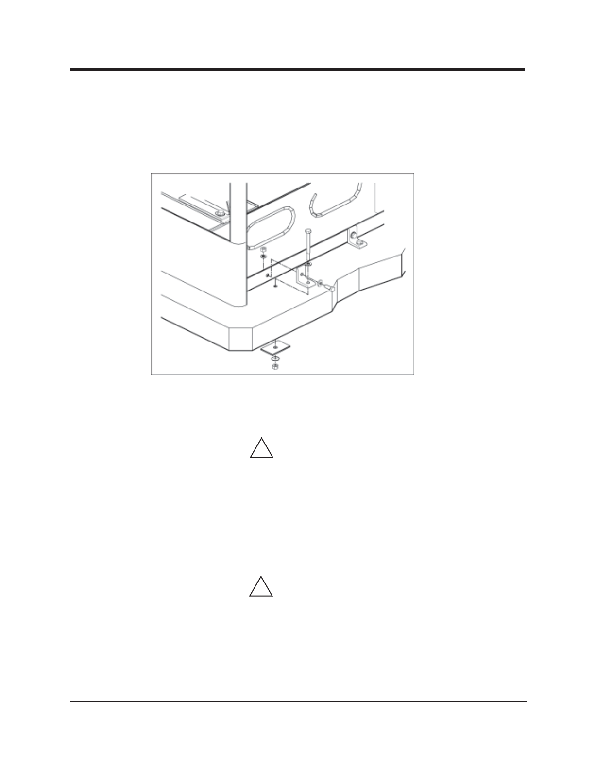
Machine Tie Down Cleats
Secure the machine to the floor of the van with the four tie down cleats provided.
This safety measure will ensure that the machine will not slide inside the van. See the
following illustration for the correct installation.
Figure 1-3 Installation Using Tie-down Cleats
Ensure that the machine is well secured to the floor of the van with the hardware
supplied. A sudden or crash stop will cause the machine to rocket forward. Protect
yourself and the machine. SECURE IT!
!
WARNING
It is recommended by the manufacturer that the exhaust from the front of the
machine be vented down under the truck to prevent carbon monoxide from
entering the job site. Always park the truck so the exhaust is blowing away
from the job site.
The manufacturer also recommends the installation of aluminum vents in the
truck roof to allow heat to escape.
!
WARNING
Never operate this machine with a portable gas can inside the truck. Doing so
increases the risk of a fire or explosion.
Mount a fire extinguisher just inside the rear or side door for emergencies.
HydraMaster Corporation
Page 17

SpitFire 3.2 Section 1-17
!
WARNING
Do not use a portable propane tank inside of the truck or van. It is dangerous
and illegal in most states.
!
WARNING
Transportation in a vehicle of any vented fuel container that presently holds or
has ever held a flammable liquid is strictly forbidden by Steamatic, Inc. and by
federal and state regulation.
!
WARNING
The engine exhaust from this product contains chemicals known to the State
of California to cause canser, birth defects or other reproductive harm.
HydraMaster Corporation
Page 18

Page 19

Page 20

Page 21
Page 22

Page 23

Page 1-20
Machine Assemblies
and Parts Lists
Figure 1-6 Machine Assembly - Front Lef t V iew
D-2793 Rev L
9
3
17
SpitFir e 3.2
2
1
20
19
20
HydraMaster Corporation
Page 24

SpitFir e 3.2
Figure 1-7 Machine Assembly - Front Right V iew
D-2793 Rev L
Page 1-21
18
10
11
4
13
12
HydraMaster Corporation
Page 25

Page 1-22
Figure 1-8 Machine Assembly - Rear Lef t View
D-2793 Rev L
SpitFir e 3.2
6
18
13
10
16
14
16
15
21
7
9
14
15
7
12
18
8
17
8
HydraMaster Corporation
Page 26

SpitFir e 3.2
Figure 1-9 Machine Assembly - Bottom View
D-2793 Rev L
Page 1-23
5
11
HydraMaster Corporation
SILENCER REMOVED FOR CLARITY
Page 27

Page 1-24
SpitFir e 3.2
Machine Assembly Parts List
Item Part Number Description Qty
1 Fig 1-10 Assembly , Frame - S pitfire 3.2 1
2 Fig 1-13 Assembly , Engine 16 HP V anguard - S pitfire 3.2 1
3 Fig 1-17 Assembly , Pump & Blower - S pitfire 3.2 1
4 Fig 1-21 Dual Heat Exchanger Assembly - Spitfire 3.2 1
5 Fig 1-22 Lower Heat Exchanger Assembly - Spitfire 3.2 1
6 000-068-015 Hose, 1/4" I.D. - Bulk 1
7 000-068-018 Hose, 1/2" I.D. Rubber - Bulk 1
8 000-068-018 Hose, 1/2" I.D. Rubber - Bulk 1
9 000-068-030 Hose, 5/32" I.D. - Bulk 1
10 000-068-410 Hose, 3/4" I.D. x 30" Lg. Pump Pick Up w/ 3/4" Ends 1
11 000-068-485 Hose,1/2" I.D. x 47" Lg. Rubber w/ 3/8 NPT & 3/8 SAE Femal 1
12 000-068-510 Hose, 3/8" x 56" Lg. Teflon w/ 1/4 NPT x 3/8 JIC Female 1
13 000-068-531 Hose, 1/2" I.D. x 30" Lg. Black 1/2 NPT x 3/8 SAE(1/2"End T 1
14 000-068-534 Hose, 3/16" I.D. x 44.50" Lg. Teflon w/ 1/8 NPT x 1/4 JIC Fem 1
15 000-068-588 Hose, Throb 1
16 000-068-619 Hose, 3/8" I.D. x 32" Lg. Teflon 1
17 000-068-660 Hose, 1/4" I.D. Fuel T rident 1
18 000-033-004 Clamp, Size #6 3
19 - - - Filter, B&S Fuel (Comes w/ Engine) 1
20 000-033-003 Clamp, Size #4 Mini 2
21 000-033-046 Clamp, 1/2 Wide x 1/2 T ube 1
HydraMaster Corporation
Page 28

SpitFir e 3.2
Figure 1-10 Frame Assembly
D-5904 Rev A
1
30
Page 1-25
25
21
20
35
34
24
26
5
6
4
2
7
32
35
20
34
21
4
2
27
7
16
28
21
15
3
14
33
13
19
18
21
19
20
29
21
19
11
7
23
23
22
9
10
12
17
14
8
HydraMaster Corporation
Page 29

Page 1-26
SpitFir e 3.2
Frame Assembly Parts List
Item Part Number Description Qty
1 000-055-024 Frame, Weldment - S pitfire 3.2 1
2 000-015-265 Bracket, Machine Tie Down - S p 3.2 4
3 Fig 1-12 Assembly , By-Pass V alve - S pitfire 3.2 1
4 000-143-017 Screw, 3/8"-16UNC x 3/4" Lg. Hex Head 4
5 000-094-014 Nut, 3/8"-16UNC Hex Zinc Plated 4
6 000-174-021 Washer, 3/8" Lock 4
7 000-106-040 Plug, Frame End 4
8 000-052-052 Quick Connect, 660 Male w/ Viton St andard 1
9 000-052-104 Insert, #66 (3/8" NPT x 3/8" Barb) 1
10 000-169-064 Valve, 3/8" NPT Full Port Ball 1
11 000-052-051 Quick Connect, 440 Female w/ EPDM O-Ring 1
12 000-074-013 Meter , Chemical Flow 1
13 000-074-007 Gauge, Pressure (0-1500 PSI) 1
14 000-174-034 Washer, 0.688" I.D. x 1.50" O.D. x 0.078" Thk. 2
15 000-052-105 Insert, #68 (3/8" NPT x 1/2" Barb) 1
16 000-033-004 Clamp, Size #6 1
17 000-057-055 Gasket, Garden Hose 1
18 000-052-097 Insert, #24 (1/8" NPT x 1/4" Barb) 2
19 000-143-126 Screw, #10-24UNC x 0.50" Lg. Hex Head 6
20 000-174-014 Washer, #10 Lock 4
21 000-174-001 Washer, #10 Flat 8
22 000-052-533 Nipple, 3/8" JIC x 1/4" NPT 1
23 000-174-007 Washer, 1/2" Flat 2
24 000-131-021 Trimlok, 5/8" x 1/8" Rubber 2
25 000-131-021 Trimlok, 5/8" x 1/8" Rubber 1
26 000-131-021 Trimlok, 5/8" x 1/8" Rubber 2
27 000-068-025 Hose, 1/4" I.D. Clear - Bulk 1
28 Fig 1-1 1 Assembly , St arter Solenoid Cover - Spitfire 3.2 1
29 000-041-192 Cover , Heat Exchanger - Weldment - S p 3.2 1
30 000-093-027 Silencer, 2" Comp act 1
HydraMaster Corporation
Page 30

SpitFir e 3.2
Frame Assembly Parts List
Item Part Number Description Qty
31 000-135-052 Regulator , Hi PSI Snubber 1
32 000-052-066 Coupler , 1/4" FPT x 1/8" FPT 1
33 000-174-038 Washer, 7/16" S.A.E. Flat 1
34 000-033-067 Clamp, 2" Cushion Loop 2
35 000-143-132 Screw, #10-24UNC x 0.75" Lg. Hex Head 2
Page 1-27
HydraMaster Corporation
Page 31

Page 1-28
4
5
Figure 1-11 Starter Solenoid Cover Assembly
D-3474 Rev A
SpitFir e 3.2
1
12
9
10
13
14
2
15
13
14
7
15
10
16
6
9
8
11
HydraMaster Corporation
Page 32

SpitFir e 3.2
Page 1-29
Starter Solenoid Cover Assembly Parts List
Item Part Number Description Qty
1 000-041-179 Cover , Starter Solenoid 1
2 000-157-022 Switch, Relay 1
3 000-157-115 Switch, 16 AMP Mini Rocker 2
4 000-084-006 Lamp, Red Pilot - Round 2
5 000-052-272 Cup, Gravity Feed Oil Blower Lubrication Port 1
6 000-052-096 Insert, #F23 (1/8" FPT x 3/16" Barb) 1
7 000-157-012 Switch, St arter Solenoid 14 HP B&S 1
8 000-056-006 Fuse Holder , Inline Weather Proof 1
9 000-174-001 Washer , #10 Flat 2
10 000-143-132 Screw, #10-24UNC x 0.75" Lg. Hex Head 2
11 000-056-008 Fuse, 15 AMP Plug In 1
12 000-094-034 Nut, #10-24UNC Nylock 1
13 000-143-141 Screw, 1/4"-20UNC x 1/2" Lg. Whiz Lock 2
14 000-174-003 Washer , 1/4" Flat 2
15 000-094-009 Nut, 1/4"-20UNC Hex Nylock 2
16 000-174-032 Washer , 3/8" Flat 3
HydraMaster Corporation
Page 33

Page 1-30
Figure 1-12 By-Pass V alve Assembly
C-5907 Rev -
SpitFir e 3.2
5
9
8
7
6
4
10
2
11
3
2
4
1
2
HydraMaster Corporation
Page 34

SpitFir e 3.2
Page 1-31
By-Pass Valve Assembly Parts List
Item Part Number Description Qty
1 000-169-158 V alve, By-Pass w/ Red Spring (0-1000 PSI) 1
2 000-052-086 Elbow, 3/8" NPT Street 3
3 000-052-128 Nipple, 3/8" NPT x 3/8" Male Propane 1
4 000-052-023 Tee, 3/8" NPT Male Street 2
5 000-169-011 Valve, Hi Temp Control 180° 1
6 000-052-084 Elbow, 1/8" NPT Street 1
7 000-052-069 Nipple, 1/8" NPT Hex 1
8 000-052-066 Coupler, 1/4" FPT x 1/8" FPT 1
9 000-052-117 Insert, #48 (1/4" NPT x 1/2" Barb) 1
10 000-052-528 Nipple, 3/8" M JIC x 3/8" NPT 1
11 000-052-105 Insert, #68 (3/8" NPT x 1/2" Barb) 1
HydraMaster Corporation
Page 35

Page 1-32
Figure 1-13 Engine Assembly
D-2649 Rev J
SpitFir e 3.2
19
18
13
14
3
15
1
11
2
16
17
4
10
9
8
7
6
12
5
HydraMaster Corporation
Page 36

SpitFir e 3.2
Item Part Number Description Qty
1 000-047-008 Engine, B&S V anguard 16 HP V -Twin 1
2 Fig. 1-14 Dash Assembly - Spit fire 3.2 1
3 Fig. 1-15 Exhaust Assembly , Spitfire 3.2 1
4 Fig. 1-16 Volt age Regulator Modification 1
5 000-049-014 Filter, 16HP Oil - All B & S 1
6 000-052-408 Nipple, 3/8" NPT x 4" Lg. 1
7 000-027-008 Cap, 3/8" FPT 1
8 000-174-004 Washer, 5/16" Flat 4
9 000-174-057 Washer, 3/8" Lock 4
10 000-094-014 Nut, 3/8"-16UNC Hex Zink Plated 4
Page 1-33
11 000-174-013 Washer , 3/8" Fender 4
12 000-143-022 Screw, 3/8"-16UNC x 1.75" Lg. Hex Head Grd 8 4
13 000-020-012 Collar, Spitfire Engine Shaft - Double Screw T ype 1
14 000-039-017 Coupler, #6 x 1" Bore 1
15 000-152-008 Sleeve, #6 Drive Coupler 1
16 000-157-115 Switch, 16 Amp Mini Rocker 1
17 000-084-006 Lamp, Red Pilot - Round 1
18 000-077-006 Key, 0.25" x 1.5" Lg. 1
19 000-143-185 Screw, 8mm x 20mm Grade 8.8 Hex Head 2
HydraMaster Corporation
Page 37

Page 1-34
Figure 1-14 Dash Assembly
D-2718 Rev B
SpitFir e 3.2
6
2
4
2
7
5
3
1
Dash Assembly Parts List
Item Part Number Description Qty
1 000-100-044 Dash, Spitefire 3.2 1
2 000-157-017 Switch, Ignition B&S 14 HP 1
3 000-074-011 Meter, Rectangular Hour 1
4 000-084-006 Lamp, Red Pilot - Round 1
5 000-143-050 Screw, #8-32UNC x 0.50" Lg. Round Head Phillips 2
6 000-094-002 Nut, #8-32UNC Hex 2
7 000-174-058 Washer,2 1/32" I.D. x 27/32" O.D. Nylon 1
HydraMaster Corporation
Page 38

SpitFir e 3.2
Figure 1-15 Exhaust Assembly
D-5909 Rev -
Page 1-35
3
1
12
4
13
12
13
7
6
12
18
5
20 18
17
10
21 17
19
11
20
9
8
2
10911
22
8
15
16
15
14
19
HydraMaster Corporation
Page 39

Page 1-36
SpitFir e 3.2
Exhaust Assembly Parts List
Item Part Number Description Qty
1 000-113-002 Radiator, Spit fire 3.2 1
2 000-015-242 Bracket, Lower Support - Radiator 1
3 000-015-300 Bracket, Upper Support - Radiator 1
4 000-090-034 Manifold, Exhaust Modified 1
5 000-125-053 Tube, Exhaust Manifold T o Hx - S p 3.2 1
6 000-033-004 Clamp, Size #6 1
7 000-052-107 Insert, #88 (1/2" NPT x 1/2" Barb) 1
8 000-094-038 Nut, 5/16"-18UNC Nylock 2
9 000-012-003 Block, Radiator Mount Pad 2
10 000-143-092 Screw, 5/16"-18UNC x 2.25" Lg. Hex Head 2
11 000-174-049 Washer , 5/16" Flat 2
12 000-143-185 Screw, 8mm x 20mm Grade 8.8 Hex Head 4
13 000-057-010 Gasket, Exhaust Manifold - Vanguard 2
14 000-174-004 Washer , 5/16" Flat 2
15 000-174-018 Washer, 5/16" Lock 2
16 000-143-090 Screw, 5/16"-24UNF x 1.00" Lg. Hex Head 2
17 000-094-081 Nut, 5/16"-18UNC Hex 2-Way Locking 4
18 000-057-016 Gasket, Exhaust Manifold 2
19 000-143-012 Screw, 5/16"-18UNC x 0.75" Lg. Hex Head 4
20 000-033-020 Clamp, Size #16 2
21 000-131-046 Insulation Sleeving, 0.054" Thk. x 1-1/2" Exhaust Tube Wrap - 1
22 000-131-009 Insulation, 1/8" x 12" - Bulk 1
HydraMaster Corporation
Page 40

SpitFir e 3.2
Figure 1-16 V olt age Regulator Modification Assembly
B-3475 Rev -
Page 1-37
Voltage Regulator Modification Assembly Parts List
Item Part Number Description Qty
1 - - - Briggs & Stratton V oltage Regulator (Comes w/ Engine) 1
2 000-178-026 Wire, 16 A WG Y ellow 2
3 000-037-033 Connector, #22 Pink Butt 4
HydraMaster Corporation
Page 41

Page 1-38
Figure 1-17 Pump & Blower Assembly
D-4050 Rev B
2
12
11
SpitFir e 3.2
18
3
6 16
5
19
17
17
18
19
1
10
8
9
7
14
15
13
HydraMaster Corporation
Page 42

SpitFir e 3.2
Page 1-39
Pump & Blower Assembly Parts List
Item Part Number Description Qty
1 000-1 1 1-133 Blower, 3003 Competitor Plus 1
2 Fig. 1-20 Assembly , Water Box - S pitfire 3.2 1
3 Fig. 1-18 Assembly , Pump - S pitfire 3.2 1
4 Fig. 1-19 Assembly , Collector Box - Spit fire 3.2 1
5 000-108-136 Protector, Belt Guard - Front - S p 3.2 1
6 000-108-137 Protector, Belt Guard - Rear - S p 3.2 1
7 000-174-068 Washer, Blower Feet 4
8 000-174-012 Washer , 1/2" SAE H/D Flat 4
9 000-094-102 Nut, 7/16"-14UNC T wo-Way Locking Hex 4
10 000-143-028 Screw, 7/16"-14UNC x 1.75" Lg. Hex Head Grd 5 Zinc 4
11 000-174-004 Washer , 5/16" Flat 4
12 000-094-038 Nut, 5/16"-18UNC Nylock 4
13 000-109-006 Pulley, 2-3/4" x 3/4" Bore 1
14 000-020-015 Collar, 7/8" Clamping 1
15 000-039-006 Coupler, #6 x 7/8" 1
16 000-010-054 Belt, Boxxer Pump Drive 1
17 000-174-001 Washer , #10 Flat 3
18 000-174-014 Washer, #10 Lock 3
19 000-143-126 Screw, #10-24UNC x 0.50" Lg. Hex Head 3
HydraMaster Corporation
Page 43

Page 1-40
Figure 1-18 Pump - Hydra II - Assembly
D-5906 Rev -
SpitFir e 3.2
17
18
1
2
3
4
5
7
6
12
19
13
3
16
15
14
9
10
11
8
HydraMaster Corporation
Page 44

SpitFir e 3.2
Page 1-41
Pump - Hydra II - Assembly Parts List
Item Part Number Description Qty
1 000-111-042 Pump, Hydra II Hi PSI 3.5 Gpm 1
2 000-052-023 Tee, 3/8" NPT Male Street 1
3 000-052-086 Elbow, 3/8" NPT Street 2
4 000-052-528 Nipple, 3/8" M JIC x 3/8" NPT 1
5 000-052-074 Nipple, 3/8" NPT Hex 1
6 000-052-087 Elbow, 1/2" NPT Street 1
7 000-052-547 Nipple, 1/2 NPT x 3/4 SAE 1
8 000-106-004 Plug, 1/2" NPT Hex 1
9 000-106-003 Plug, 3/8" NPT Hex 1
10 000-020-013 Coupler, H x 24mm Spit fire 3.2 & 4.0 1
11 000-109-017 Pulley , Spitfire Pump 1
12 000-068-219 Hose, Spitfire Pump Drain 1
13 000-143-126 Screw, #10-24UNC x 0.50" Lg. Hex Head 1
14 000-174-001 Washer , #10 Flat 1
15 000-174-014 Washer, #10 Lock 1
16 000-015-909 Bracket, Pump T o Belt Guard - S p 3.2 1
17 000-174-049 Washer , 5/16" Flat 1
18 000-174-018 Washer, 5/16" Lock 1
19 000-143-571 Screw, 8mm x 1.25 x 10mm Lg. Hex Head Z/P 1
HydraMaster Corporation
Page 45

Page 1-42
Figure 1-19 Collector Box Assembly
D-5908 Rev A
SpitFir e 3.2
13
14
29
16
15
28
17
19
18
7
22
1
9
12
11
26
20
20
21
26
5
23
20 2023
18
19
27
20
91117
14
15
16
3
2
4
24
20
2225
23
6
10
8
HydraMaster Corporation
Page 46

SpitFir e 3.2
Page 1-43
Collector Box Assembly Parts List
Item Part Number Description Qty
1 000-013-061 Box, Blower Collector - Spitfire 3.2 1
2 000-015-746 Bracket, Pump Idler - Boxxer 421 1
3 000-154-049 Spacer , Pump Idler Mounting - Boxxer 421 1
4 000-105-250 Plate, Pump Idler - Spitfire 3.2 1
5 000-057-197 Gasket, Collector Box To Blower - Spitfire 3.2 1
6 000-109-093 Pulley , 3" x 0.635/0.640 Bore, “A” Sect. Ball Bearing 1
7 000-052-106 Insert, 1/8" NPT x 5/32" Barb x 90° 1
8 000-143-041 Screw, 1/2"-13UNC x 2.25" Lg. Hex Head 1
9 000-094-014 Nut, 3/8"-16UNC Hex Zink Plated 2
10 000-174-012 Washer , 1/2" SAE H/D Flat 1
11 000-174-032 Washer , 3/8" Flat 2
12 000-174-057 Washer, 3/8" Lock 1
13 000-001-027 Adapter, Blower To Collector Box - Spit fire 1
14 000-143-126 Screw, #10-24UNC x 0.50" Lg. Hex Head 2
15 000-174-001 Washer , #10 Flat 2
16 000-174-014 Washer, #10 Lock 2
17 000-143-018 Screw, 3/8"-16UNC x 1.00" Lg. Grade 8 4
18 000-174-005 Washer , 3/8" Flat 4
19 000-174-021 Washer, 3/8" Lock 4
20 000-174-003 Washer , 1/4" Flat 10
21 000-094-009 Nut, 1/4"-20UNC Hex Nylock 2
22 000-143-333 Screw, 1/4"-20UNC x 0.50" Lg. Hex Head 6
23 000-174-019 Washer, 1/4" Lock 6
24 000-015-905 Bracket, Belt Guard Mounting - Left - Sp 3.2 1
25 000-015-904 Bracket, Belt Guard Mounting - Right - Sp 3.2 1
26 000-143-001 Screw, 1/4"-20UNC x 0.75" Lg. Hex Head 2
27 000-157-022 Switch, Relay 1
28 000-056-006 Fuse Holder, Inline Weather Proof 1
29 000-056-007 Fuse, 10 AMP Plug In 1
HydraMaster Corporation
Page 47

Page 1-44
Figure 1-20 Water Box Assembly
D-5905 Rev C
SpitFir e 3.2
5
5
2
12
8
7
3
6
14
13
19
18
6
11
10
4
6
14
13
9
12
HIDDEN
16
17
13
15
16
17
1
4
18
HIDDEN
16
16
17
18
1
12
HydraMaster Corporation
Page 48

SpitFir e 3.2
Page 1-45
Water Box Assembly Parts List
Item Part Number Description Qty
1 000-015-851 Bracket, Water Box Mounting - S p 3.2 1
2 000-159-105 Tank, Poly W ater Box - Modified 1
3 000-041-004 Cover, Poly W ater Box Mod. w/ V ent 1
4 000-157-031 Switch, Side Mount w/ Bulkhead Fitting 3
5 000-143-314 Screw, #8 x 1/2" Lg. Pan Head 6
6 000-052-086 Elbow, 3/8" NPT Street 3
7 000-068-327 Hose, 1/2" I.D. Clear Braid - Bulk 1
8 000-033-004 Clamp, Size #6 1
9 000-169-120 V alve, Chemical & Hi-T emp Solenoid - 12 V olt 1
10 000-052-074 Nipple, 3/8" NPT Hex 1
11 000-181-008 Venturi, Low PSI Injector - Modified 1
12 000-052-105 Insert, #68 (3/8" NPT x 1/2" Barb) 3
13 000-097-041 O-Ring, 1/2" Bulkhead 3
14 000-052-660 Bulkhead, 3/8" FPT x 3/8" FPT 2
15 000-052-661 Insert, 3/4" Barb x Straight 1
16 000-174-032 Washer , 3/8" Flat 6
17 000-143-017 Screw, 3/8"-16UNC x 3/4" Lg. Hex Head 6
18 000-094-097 Nut,1-14" Brass Water Box 5
19 000-174-063 Washer , 1.5" O.D. x 1.073" I.D. x 0.075" Thk. 1
HydraMaster Corporation
Page 49

Page 1-46
Figure 1-21 Dual Heat Exchanger Assembly
D-3090 Rev B
SpitFir e 3.2
17
19
20
17
18
16
12
14
17
1
16
11
10
12
2
14
4
2
2
15 2
4 3
6
5
21 8
7
9
13
HydraMaster Corporation
Page 50

SpitFir e 3.2
Page 1-47
Dual Heat Exchanger Assembly Parts List
Item Part Number Description Qty
1 000-038-026 Heat Exchanger, Dual - S pitfire 3.2 1
2 000-052-085 Elbow, 1/4" NPT Street 5
3 000-052-533 Nipple, 3/8" JIC x 1/4" NPT 1
4 000-052-090 Tee, 1/4" NPT Branch M-F-F 2
5 000-052-171 Housing, 1/4 Brass Filter 1
6 000-049-052 Filter Cartridge, 1/4" 1
7 000-094-028 Nut, Brass Jet Assembly 1
8 000-052-585 Nipple, Teejet Mod. For Orifice 1
9 000-052-066 Coupler, 1/4" FPT x 1/8" FPT 1
10 000-052-527 Nipple, 1/4" SAE x 1/4" NPT 1
11 000-108-023 Protective Insulation Blanket - Spitfire 3.2 1
12 000-033-060 Clamp, Size #80 Hose 2
13 000-068-530 Hose, 3/8" x 7.5" Lg. T eflon w/ 1/4" NPT & 3/8" JIC F Ends 1
14 000-140-005 Rivet, 3/16" x 0.50" Lg. Pop (Ab6-6A) 2
15 000-068-533 Hose, 3/8" x 9" Lg. T eflon w/ 1/4" NPT & 3/8" JIC F Ends 1
16 000-033-068 Clamp, 1-1/2" Muffler 2
17 000-131-037 Wrap, Exhaust Insulation - 2" Wide - Bulk 3
18 000-131-046 Insulation Sleeving, 0.054" x 1-1/2" Exhaust Tube Wrap-Silic 1
19 000-033-009 Clamp, Size #24 Hose 1
20 000-068-260 Hose, 1-1/4" x 31" Lg. S/S Flex Exhaust 1
21 000-180-010 Orifice, 0.039" Plate 1
HydraMaster Corporation
Page 51

Page 1-48
Figure 1-22 Lower Heat Exchanger Assembly
D-2665 Rev B
SpitFir e 3.2
3
8
13
6
2
1
9
10
5
4
18
7
8
12
9
10
11
15
16
17
6
14
18
HydraMaster Corporation
Page 52

SpitFir e 3.2
Page 1-49
Lower Heat Exchanger Assembly Parts List
Item Part Number Description Qty
1 000-038-018 Core, 3" Copper Heat Exchanger - Spitfire 3.2 1
2 000-052-343 Adapter, Heat Exchanger Inlet 1
3 000-001-017 Adapter, Silencer Outlet - S pitfire 3.2 1
4 000-052-321 Exhaust Turn Down Fitting 1
5 000-033-013 Clamp, Size #48 Hose 1
6 000-143-132 Screw, #10-24UNC x 0.75" Lg. Hex Head 2
7 000-094-034 Nut, #10-24UNC Nylock 1
8 000-174-001 Washer, #10 Flat 2
9 000-052-087 Elbow, 1/2" NPT Street 2
10 000-052-064 Bushing, 1/2" NPT x 3/8" FPT 2
11 000-052-023 Tee, 3/8" NPT Male Street 1
12 000-015-297 Bracket, Mix Tank Mount - SP 4.0 1
13 000-174-014 Washer, #10 Lock 1
14 000-068-536 Hose, 1/2" x 16" Lg. Black w/ 3/8" NPT & 3/8 SAE F Ends 1
15 000-052-105 Insert, #68 (3/8" NPT x 1/2" Barb) 1
16 000-052-083 Elbow, 3/8" NPT S treet x 45° 1
17 000-068-297 Hose, 1/2" x 14" Lg. Black w/ 3/8" Ends 1
18 000-033-004 Clamp, Size #6 2
HydraMaster Corporation
Page 53

Page 1-50
Figure 1-23 Recovery Tank Assembly
D-2651 Rev M
3
SpitFir e 3.2
20
21
22
5
HIDDEN
17
18
26
24
15
14
16
15
24
19
22
HIDDEN
2
7
6
9
8
23
24
20
21
1
4
10
25
11
12
13
HydraMaster Corporation
Page 54

SpitFir e 3.2
Page 1-51
Recovery Tank Assembly Parts List
Item Part Number Description Qty
1 000-159-041 Tank, Recovery - Weldment - Spitfire 1
2 Fig. 1-24 Assembly , Recovery Tank Cover - Spit fire 1
3 000-049-007 Filter, 2" NPT Blower s/s 1
4 000-052-224 Elbow , 2" NPT x 2" Barb 1
5 000-001-036 Adapter, Ø2.75 x 2" NPT T ank Inlet Elbow 1
6 000-052-219 Adapter , 2" NPT x 2" F Slip 1
7 000-052-223 Elbow , 2" F Slip x 2" M Slip 1
8 000-052-404 Adapter , 3" F Slip x 2" F Slip 1
9 000-125-052 Tube, 2" PVC x 1.50" Lg. Filter Bag Adapter Sleeve 1
10 000-052-182 Nipple, 1-1/2" NPT Close Galvanized 1
11 000-169-022 Valve, 1-1/2" Full Port Ball 1
12 000-052-226 Insert,1-1/2" NPT x 1-1/2" Barb (Grey) 1
13 000-106-019 Plug, 1-1/2" NPT 1
14 000-052-086 Elbow, 3/8" NPT S treet 1
15 000-052-105 Insert, #68 (3/8" NPT x 1/2" Barb) 2
16 000-052-083 Elbow, 3/8" NPT S treet x 45° 1
17 000-012-002 Block, 6 Post T erminal 1
18 000-143-051 Screw, #8-32UNC x 0.75" Lg. Binder Head Phillips 2
19 000-094-059 Nut, #8-32UNF Nylock 2
20 000-086-008 Latch, Bungie 2
21 000-143-539 Screw, #6-32UNC x 0.50" Lg. Button Head Allen 4
22 000-094-063 Nut, #6-32UNC Nylock 4
23 000-049-030 Filter Bag, 92+Truck Mount 1
24 000-131-121 Bumper Materail - Split 1
25 000-106-046 Plug, 1-1/4" NPT 1
26 000-157-090 Float, Lever Switch 1
HydraMaster Corporation
Page 55

Page 1-52
Figure 1-24 Recovery Tank Cover Assembly
C-2704 Rev F
SpitFir e 3.2
9
7
6
5
9
7
8
2
4
3
8
1
Recovery Tank Cover Assembly Parts List
Item Part Number Description Qty
1 000-041-170 Cover, Recovery T ank - Weldment - S pitfire 1
2 000-105-005 Plate, V acuum Relief - Recovery T ank 1
3 000-155-002 Spring, V acuum Relief V alve 1
4 000-143-009 Screw, 1/4"20UNC x 2.50" Lg. Hex Head 1
5 000-174-003 Washer, 1/4" Flat 2
6 000-094-010 Nut, 1/4"-20UNC Hex 2
7 000-086-008 Latch, Bungie - Strike 2
8 000-143-539 Screw, #6-32UNC x 0.50" Lg. Button Head Allen 4
9 000-094-063 Nut, #6-32UNC Nylock 4
HydraMaster Corporation
Page 56

SpitFir e 3.2
Figure 1-26 APO Assembly
D-2799 Rev C
23
18
21
20
9
22
19
Page 1-53
RECOVERY TANK WALL
Ø1.625 HOLE FOR APO
9
10
11
10
9
17
9
15
12
13
10
14
8
7
6
16
5
4
24
1
2
3
HydraMaster Corporation
Page 57

Page 1-54
SpitFir e 3.2
APO Assembly Parts List
Item Part Number Description Qty
1 000-055-041 Frame, APO - T op Exit S tyle - Weldment 1
2 000-049-058 Screen, APO Filter - Boxxer 2
3 000-111-012 Pump, Truck Mount W aste Pump Out 1
4 000-033-009 Clamp, Size #24 Hose 2
5 000-052-234 Elbow , 1" F Slip x 1" F Slip 1
6 000-052-235 Bushing, 3/4" FPT x 1" M Slip 1
7 000-052-329 Nipple, 3/4" Hex - Modified 1
8 000-169-009 V alve, 3/4" FPT Swing Check 1
9 000-052-236 Adapter , 3/4" NPT x 1" F Slip 4
10 000-057-055 Gasket, Garden Hose 3
11 000-052-244 Swivel, 3/4" Female Garden x 3/4" Female Garden 1
12 000-052-340 Elbow, 3/4" NPT S treet 1
13 000-052-281 Nipple, 3/4" NPT x 3/4" Male Garden Hose 1
14 000-027-014 Cap, Garden Hose 1
15 000-052-339 Coupler, 3/4" FPT x 3/4" FPT Bulkhead Fitting 1
16 000-052-185 Cuff, 1-1/2" Vacuum Hose - Modified 1
17 000-068-204 Hose, Ø1" I.D. Kana Flex 1
18 000-068-204 Hose, Ø1" I.D. Kana Flex 1
19 000-060-009 Grommet, 1/2" I.D. w/ 3/32" Groove 1
20 000-037-047 Connector, 2 Pole - Male W ater Tight 1
21 000-037-048 Connector, 2 Pole - Female Water Tight 1
22 000-037-050 Terminal, Male Pin- 4 Pole Water Tight 2
23 000-037-102 Pin T erminal, #18 w/o Insulation - Female 2
24 000-143-126 Screw, #10-24UNC x 0.50" Lg. Hex Head 2
HydraMaster Corporation
Page 58

SpitFir e 3.2
Figure 1-27 85 Gallon Rotomolded T ank Assembly - Front View
D-5566 Rev B
Page 1-55
17
27
28
2
6
35
33
3
19
1
29
37
21
22
38
36
HydraMaster Corporation
11
12
13 14 34
Page 59

Page 1-56
Figure 1-28 85 Gallon Rotomolded T ank Assembly - Rear V iew
D-5566 Rev B
SpitFir e 3.2
17
5
23
26
24
25
4
7
6
8
9
10
31
32
15
16
39
34
18
20
30
1
15
HydraMaster Corporation
Page 60

SpitFir e 3.2
Page 1-57
85 Gallon Rotomolded Tank Assembly Parts List
Item Part Number Description Qty
1 000-159-116 Tank, Boxxer Fresh Water - Rotomolded 1
2 000-159-016 Jug, 5 Gallon Plastic Chemical - Standard 1
3 000-169-202 V alve, 3/4" FPT Ball V alve 1
4 000-041-004 Cover, Poly W ater Box Mod. w/ V ent 1
5 000-143-314 Screw, #8 x 1/2" Lg. Pan Head 6
6 000-169-167 Valve, Mechanical Incoming W ater - Water Box 1
7 000-005-007 Float, Water Box 1
8 000-143-336 Screw, #10-32UNF x 0.25" Lg. Pan Head Phillips 1
9 000-174-063 Washer, 1.5" O.D. x 1.073" I.D. x 0.075" Thk. 1
10 000-052-086 Elbow, 3/8" NPT S treet 1
11 000-143-198 Screw, 3/8"-16UNC x 4" Lg. Hex Head Full Thread 6
12 000-174-005 Washer , 3/8" Flat 6
13 600-011-003 Tie Down Cleat Washer 6
14 000-094-015 Nut, 3/8"-16UNC Hex 2-Way Locking 6
15 000-052-253 Elbow, 1/8" NPT x 1/4" Barb 2
16 000-068-025 Hose, 1/4" I.D. Clear 1
17 000-111-170 Pump, Flojet Fresh Water 1
18 000-052-087 Elbow, 1/2" NPT S treet 1
19 000-143-565 Screw, 1/4-20 UNC x 0.375" Lg. Button Head 2
20 000-052-130 Insert, #810 Brass 1
21 000-143-012 Screw, 5/16"-18UNC x 0.75" Lg. Hex Head 4
22 000-174-049 Washer , 5/16" Flat 4
23 000-052-107 Insert, #88 (1/2" NPT x 1/2" Barb) 1
24 000-052-160 Insert, 3/4" M Garden x 1/2" Barb 1
25 000-049-020 Filter, Screen - Medium 1
26 000-068-018 Hose, 1/2" I.D Bulk 1
27 000-068-069 Hose, 3/4" I.D. Weatherhead Blue - Bulk 1
28 000-033-029 Clamp, Size 12 Hose 2
29 000-105-313 Plate, Hydramaster Name- Roto T ank 1
30 000-068-020 Hose, .625" I.D. - Green S tripe 1
HydraMaster Corporation
Page 61

Page 1-58
SpitFir e 3.2
85 Gallon Rotomolded Tank Assembly Parts List
Item Part Number Description Qty
31 000-052-075 Nipple, 3/8" NPT x 1/2" NPT 1
32 000-052-052 Quick Connect, 660 Male w/ Viton S tandard 1
33 000-052-326 Nipple, 3/4" NPT Close 1
34 000-055-169 Frame, Rotomolded Fresh Water T ank - Boxxer 1
35 000-052-726 Elbow, 3/4" S treet (Grey) 1
36 000-052-105 Insert, #68 (3/8" NPT x 1/2" Barb) 1
37 000-052-408 Nipple, 3/8" NPT x 4" Lg. 1
38 000-052-142 Elbow, 3/8" FPT x FPT 1
39 000-005-008 Sight Float Bead, 5mm Red W ally Whale 1
HydraMaster Corporation
Page 62

SpitFir e 3.2
Page 1-59
Figure 1-29 85 Gallon Rotomolded T ank w/ S pitFire 3.2 Assembly - Right V iew
D-5819 Rev A
HIDDEN
24
25
22
26
27
28
20
1
HydraMaster Corporation
11
12
14
15
18
7
8
3
10
19
HIDDEN
6
4
7
11
3
15
17
2
HIDDEN
Page 63

Page 1-60
SpitFir e 3.2
Figure 1-30 85 Gallon Rotomolded T ank w/ S pitFire 3.2 Assembly - Lef t V iew
D-5819 Rev A
5
29
5
26
HIDDEN
HydraMaster Corporation
Page 64

SpitFir e 3.2
Page 1-61
85 Gallon Rotomolded Tank w/ SpitFire 3.2 Assembly Parts List
Item Part Number Description Qty
1 Fig. 1-26 & 1-27 Assembly , Rotomolded Tank - Boxxer 1
2 000-015-265 Bracket, Machine T ie Down - Sp 3.2 4
3 000-052-226 Insert,1-1/2" NPT x 1-1/2" Barb (Grey) 2
4 000-052-169 Cuff, 2" V acuum Hose 2
5 000-033-012 Clamp, Size #44 Hose 2
6 000-015-884 Bracket, Dump & V acuum Mounting - Boxxer 1
7 000-052-221 Insert, 2" NPT x 2" Barb (Grey) 2
8 000-027-014 Cap, Garden Hose 1
9 000-052-281 Nipple, 3/4" NPT x 3/4" Male Garden Hose 1
10 000-169-022 Valve, 1-1/2" Full Port Ball 1
11 000-033-063 Clamp, 1-1/2" T -Bolt 2
12 000-068-135 Hose, 1.5" I.D. Red Stripe 1
13 000-052-182 Nipple, 1-1/2" NPT Close Galvanized 1
14 000-143-017-1 Screw , 3/8"-16UNC x 3/4" Lg. Hex Head 4
15 000-174-057 Washer, 3/8" Lock 8
16 000-094-014 Nut, 3/8"-16UNC Hex Zink Plated 4
17 000-174-032 Washer , 3/8" Flat 4
18 000-143-096 Screw, 3/8"-16UNC x 1.00" Lg. Hex Head 4
19 000-057-055 Gasket, Garden Hose 1
20 000-068-039 Hose, 2" I.D. Grey V acuum (Black 068-042) 1
21 000-052-053 Quick Connect, 3/8 Female 1
22 000-052-086 Elbow, 3/8" NPT S treet 1
23 000-052-105 Insert, #68 (3/8" NPT x 1/2" Barb) 1
24 000-033-117 Clamp, 1" Cushion Loop w/ 7/16" Mount Hole 1
25 000-068-018 Hose, 1/2" I.D. Black Bulk 1
26 000-033-004 Clamp, Size #6 2
27 Fig. 1-6 - 1-9 Assembly, Machine - S pitfire 3.2 1
28 Fig. 1-23 Assembly , Recovery Tank For 85 RMT - S p 3.2 1
29 000-068-133 Hose, 2.75" I.D. 1
HydraMaster Corporation
Page 65

Page 1-62
Figure 1-31 Chemical Jug Tray Assembly
C-4945 Rev C
SpitFir e 3.2
9
2
7
5
4
10
16
10
11
17
18
7
6
8
3
10
19
12
14
1
13
4
15
5
HydraMaster Corporation
Page 66

SpitFir e 3.2
Page 1-63
Chemical Jug Tray Assembly Parts List
Item Part Number Description Qty
1 000-166-021 Tray, Chemical Jug - Outer - Weldment 1
2 000-166-025 Tray, Chemical Jug - Inner 1
3 000-078-039 Vacuum Inlet S topper 1
4 000-143-001 Screw, 1/4"-20UNC x 0.75" Lg. Hex Head 2
5 000-174-019 Washer, 1/4" Lock 2
6 000-169-022 Valve, 1-1/2" Full Port Ball 1
7 000-052-226 Insert,1-1/2" NPT x 1-1/2" Barb (Grey) 2
8 000-052-182 Nipple, 1-1/2" NPT Close Galvanized 1
9 000-159-016 Jug, 5 Gallon Plastic Chemical - Standard 1
10 000-174-003 Washer , 1/4" Flat 4
11 000-015-720 Bracket, Apo Outlet Mounting - W eldment 1
12 000-027-014 Cap, Garden Hose 1
13 000-052-338 Insert, #1212 (3/4" NPT x 3/4" Barb) 1
14 000-057-055 Gasket, Garden Hose 1
15 000-169-009 Valve, 3/4" FPT Swing Check 1
16 000-174-050 Washer , 1" Flat 1
17 000-174-063 Washer , 1.5" O.D. x 1.073" I.D. x 0.075" Thk. 1
18 000-052-281 Nipple, 3/4" NPT x 3/4" Male Garden Hose 1
19 000-094-009 Nut, 1/4"-20UNC Hex Nylock 2
HydraMaster Corporation
Page 67

Page 68

Page 69

Page 70

Page 71

Page 72

Page 73

Page 74

Page 75

Page 76

Page 77

Page 78

Page 79

Page 80

Page 81

Page 82

Page 83

Page 84

Page 85

Page 86

Page 87

Page 88

Page 89

Page 90

Page 91

Page 92

Page 93

Page 94

Page 95

Page 96

Page 97

Page 98

Page 99

Page 100

 Loading...