

Page 1

HYDRAMASTER
11015 47th Avenue W, Mukilteo, WA 98275
MAXX
Corporation
450D/470D/
450 Diesel
Machine Serial Number________________________
Copyright© 2007
HYDRAMASTER© Corporation
Mukilteo, Washington
MAN-182-047
No part of this manual may be reproduced or used in any form or by any means (i.e. graphic, electronic, photocopying or
electronic retrieval systems) without the express written permission of the HYDRAMASTER© Corporation. All rights reserved.
Revised September 12, 2007
Page 2

MAXX 450D/470D/450 Diesel
HydraMaster Corporation
Page 3

MAXX 450D/470D/450 Diesel
Table of Contents
GENERAL INFORMATION......................................................................... Section 1
Telephone Numbers........................................................................... 1-2
Precautions ....................................................................................... 1-3
System Operation ............................................................................. 1-7
Machine Specifications ..................................................................... 1-8
Spare Parts Recommendation .......................................................... 1-11
Spare Parts List ...................................................................... 1-11
Responsibilities................................................................................. 1-13
Vehicle Preparation ........................................................................... 1-15
High Altitude Operation Preparation .................................................. 1-19
Local Water Precautions ................................................................... 1-21
Waste Water Disposal Advisory .............................................. 1-22
Map ........................................................................................ 1-24
Machine Assemblies and Parts Lists ................................................. 1-25
CLEANING AND CHEMICALS .................................................................. Section 2
pH Chart ............................................................................................ 2-3
OPERATING INSTRUCTIONS ................................................................... Section 3
Start Up ............................................................................................. 3-1
Shut Down ......................................................................................... 3-3
Freeze Guard .................................................................................... 3-5
Freeze Protection of Pump-In System ..................................... 3-8
HydraMaster Corporation
Page 4

MAXX 450D/470D/450 Diesel
MAXX 450 DIESEL ........................................................................................... Section 4
Diesel Fuel Flow Diagram .................................................................................. 4-2
Diesel Fuel Filter/Separator ............................................................................... 4-3
Diesel Wiring Schematic .................................................................................... 4-4
Diesel Wiring Diagrams .....................................................................................4-5
WATER AND CHEMICAL SYSTEM .................................................................... Section 5
Solution Flow Diagram ........................................................................................ 5-2
Chemical System Flow Diagram .......................................................................... 5-3
Exhaust, Vacuum, Coolant and APO Diagram ....................................................... 5-4
Chemical Tank Troubleshooting ............................................................................ 5-5
HIGH PRESSURE PUMP ................................................................................... Section 6
Pump Maintenance .............................................................................................. 6-1
Service ............................................................................................................... 6-3
Cat Pump Assembly Drawing and Parts List ......................................................... 6-7
Pump Troubleshooting ......................................................................................... 6-9
CLEANING WAND PARTS ................................................................................. Section 7
Cleaning Wand Assembly Drawings and Parts Lists .............................................. 7-1
VACUUM SYSTEM ............................................................................................. Section 8
Blower Troubleshooting ........................................................................................ 8-3
Roots Blower Instruction Booklet
ENGINE TROUBLESHOOTING .........................................................................Section 9
HydraMaster Corporation
Page 5

MAXX 450D/470D/450 Diesel
ELECTRICAL SYSTEM ....................................................................................Section 10
Wiring Schematic for 450D and 470D Models ..................................................... 10-2
Wiring Diagrams for 450D and 470D Models........................................... 10-3 —10-5
MACHINE MAINTENANCE ............................................................................ Section 11
Daily .............................................................................................................. 11-1
Weekly, Monthly ................................................................................................ 11-2
Quarterly, De-scaling ........................................................................................ 11-3
Machine Maintenance ...................................................................................... 11-4
Maintenance Logs
HOW TO ORDER PARTS ............................................................................... Section 12
WARRANTY INFORMATION .......................................................................... Section 13
Golden Guarantee
ACCESSORIES .............................................................................................. Section 14
PRODUCT UPDATES .................................................................................... Section 15
HydraMaster Corporation
01/29/01
Page 6

MAXX 450D/470D/450 Diesel
List of Figures
Fig 1-1 Roof Vent ......................................................................................... 1-16
Fig 1-2 Recommended Placement ............................................................. 1-16
Fig 1-3 Tie-down Cleats .............................................................................. 1-17
Fig 1-4 Actuator Location............................................................................. 1-20
Fig 1-5 Hard Water Map .............................................................................. 1-24
Machine Assemblies:
Fig 1-7 Frame Assembly-View 1 ................................................................. 1-26
Fig 1-8 Frame Assembly-View 2 ................................................................. 1-27
Fig 1-9 100 Gallon Universal Recovery Tank Assembly .............................. 1-30
Fig 1-10 100 Gallon Universal Recovery Tank Cover .................................... 1-33
Fig 1-11 Vacuum Relief Valve Assembly ....................................................... 1-34
Fig 1-12 Dash Assembly ............................................................................... 1-35
Fig 1-13 Lower Dash Plumbing Connection Panel Assembly ....................... 1-37
Fig 1-14 Upper Dash Instrument Panel Assembly ........................................ 1-39
Fig 1-15 Control Panel Assembly .................................................................. 1-41
Fig 1-16 Bypass Heat Exchanger.................................................................. 1-43
Fig 1-17 Water-to-Water Heat Exchanger ..................................................... 1-44
Fig 1-18 Water Box Assembly ....................................................................... 1-46
Fig 1-19 CAT 3CP Pump Assembly .............................................................. 1-48
Fig 1-20 Air Pump Assembly ......................................................................... 1-50
Fig 1-21 Chemical Pump Assembly .............................................................. 1-51
HydraMaster Corporation
Page 7

MAXX 450D/470D/450 Diesel
Fig 1-22 Dura-Flow APO Assembly (Automatic Pump Out) .......................... 1-52
Fig 1-23 Fuel Pump Assembly ...................................................................... 1-54
Fig 1-24 Diverter Valve Actuator Assembly .................................................... 1-55
Fig 1-25 Blower MD 4005 Assembly.............................................................. 1-57
Fig 1-26 Blower MD 4007 Assembly.............................................................. 1-59
Fig 1-27 Exhaust Assembly - View 1 ............................................................. 1-61
Fig 1-28 Exhaust Assembly - View 2 ............................................................. 1-62
Fig 1-29 Hi PSI Manifold Assembly ................................................................ 1-64
Fig 1-30 Bypass Valve Assembly .................................................................. 1-66
Fig 1-31 Maxx 450D Daihatsu Engine Assembly - View 1 ............................. 1-68
Fig 1-32 Maxx 450D Daihatsu Engine Assembly - View 2 ............................. 1.69
Fig 1-33 Maxx 470D Daihatsu Engine Assembly - View 1 ............................. 1-73
Fig 1-34 Maxx 470D Daihatsu Engine Assembly - View 2 ............................. 1-74
Fig 1-35 Engine Cover Support Assembly ..................................................... 1-78
Fig 1-36 Chemical Jug Tray Assembly .......................................................... 1-80
Fig 1-37 Dash Assembly - Maxx 450 Diesel .................................................. 1-82
Fig 1-38 Lower Dash Plumbing Panel Assembly - Maxx 450 Diesel ............. 1-85
Fig 1-39 By-Pass Valve Assembly - Maxx 450 Diesel ................................... 1-87
Fig 1-40 Daihatsu Engine Assembly - Maxx 450 Diesel - View 1 .................. 1-89
Fig 1-41 Daihatsu Engine Assembly - Maxx 450 Diesel - View 2 .................. 1-90
Fig 1-42 Water To Water HX Assembly - Maxx 450 Diesel ............................ 1-94
Fig 1-43 Electrical Control Panel Assembly - Maxx 450 Diesel ..................... 1-96
Fig 2-1 pH Chart .......................................................................................... 2-3
Fig 2-2 Cleaning Stroke Procedure.............................................................. 2-3
HydraMaster Corporation
Page 8

MAXX 450D/470D/450 Diesel
Fig 3-1 Recirculation Fitting ......................................................................... 3-4
Fig 4-1 Diesel Flow Diagram ....................................................................... 4-2
Fig 4-2 Diesel Fuel Filter with Manual Priming Pump,
Water Separator with Electirc Motor................................................ 4-3
Fig 4-3 Diesel Wiring Schematic ................................................................. 4-4
Fig 4-4 Diesel Wiring Diagram Sheet 1 ....................................................... 4-5
Fig 4-5 Diesel Wiring Diagram Sheet 2 ....................................................... 4-6
Fig 4-6 Diesel Wiring Diagram Sheet 3 ....................................................... 4-7
Fig 5-1 Water Flow Diagram ....................................................................... 5-2
Fig 5-2 Chemical System Flow Diagram .................................................... 5-3
Fig 5-3 Exhaust, Vacuum, Coolant and APO Diagram ................................ 5-4
Fig 6-1 Servicing the Valves ............................................................... 6-2
Fig 6-2 Servicing the Low Pressure and High Pressure Seals............. 6-3
Fig 6-3 Cat Pump ............................................................................... 6-6
Fig 7-1 Valve Assembly ...................................................................... 7-1
Fig 7-2 Solution Valve Assembly ......................................................... 7-2
Fig 7-3 Valve Stem Assembly ............................................................. 7-3
Fig 7-4 HydraHoe Wand Assembly ..................................................... 7-4
Fig 10-1 Wiring Schematic for 450 and 470 Models ............................. 10-2
Fig 10-2 Wiring Diagram Sht 2 for 450 and 470 Models ....................... 10-3
Fig 10-3 Wiring Diagram Sht 3 for 450 and 470 Models ....................... 10-4
Fig 10-4 Wiring Diagram Sht 4 for 450 and 470 Models ....................... 10-5
HydraMaster Corporation
Page 9

MAXX 450D/470D/450 Diesel
Quick Reference
HydraMaster Corporation
Page 10
Quick Reference
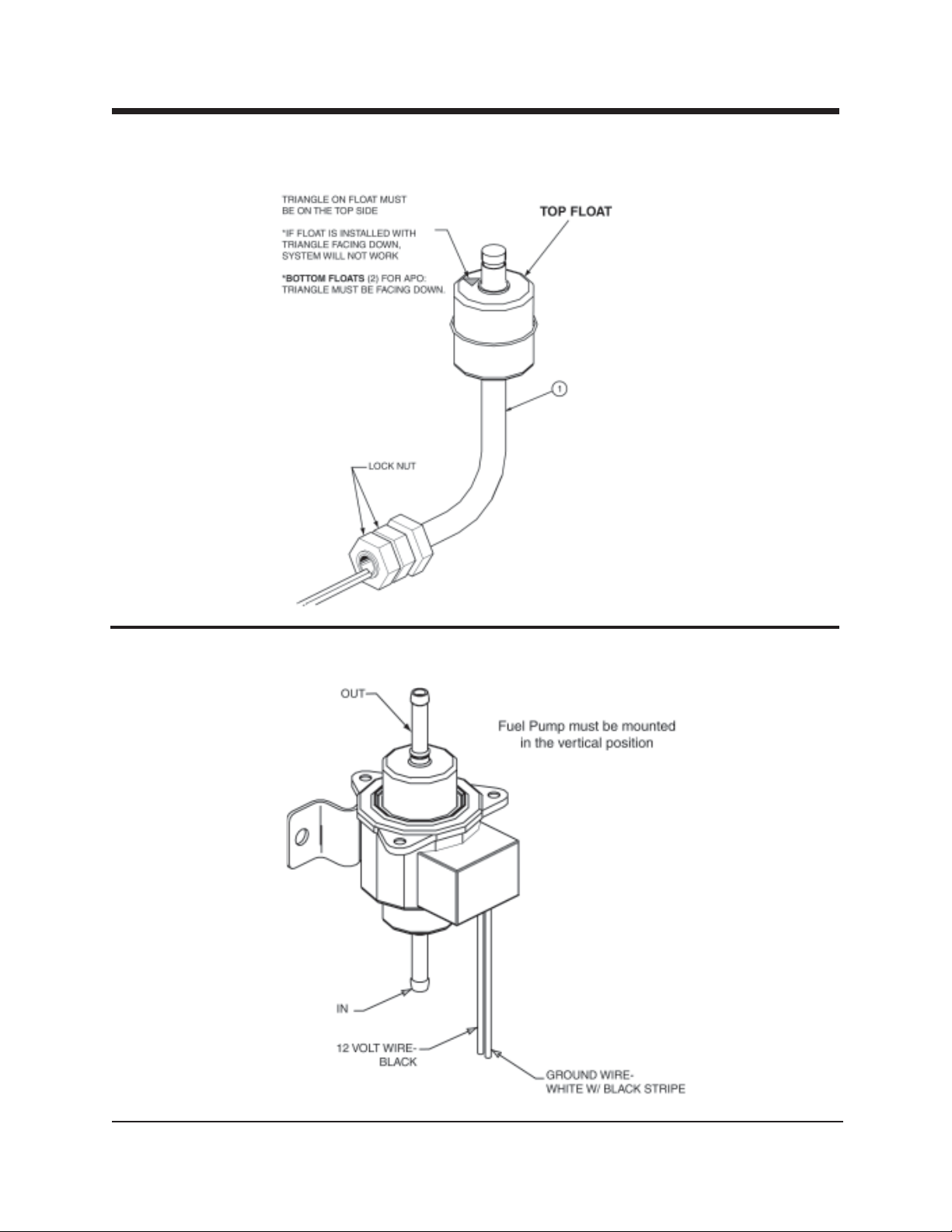
Recovery Tank Float Switch-Top Float Shown
B4624 Rev—
MAXX 450D/470D/450 Diesel
Fuel Pump Assembly
B4627 Rev—
HydraMaster Corporation
Page 11
MAXX 450D/470D/450 Diesel
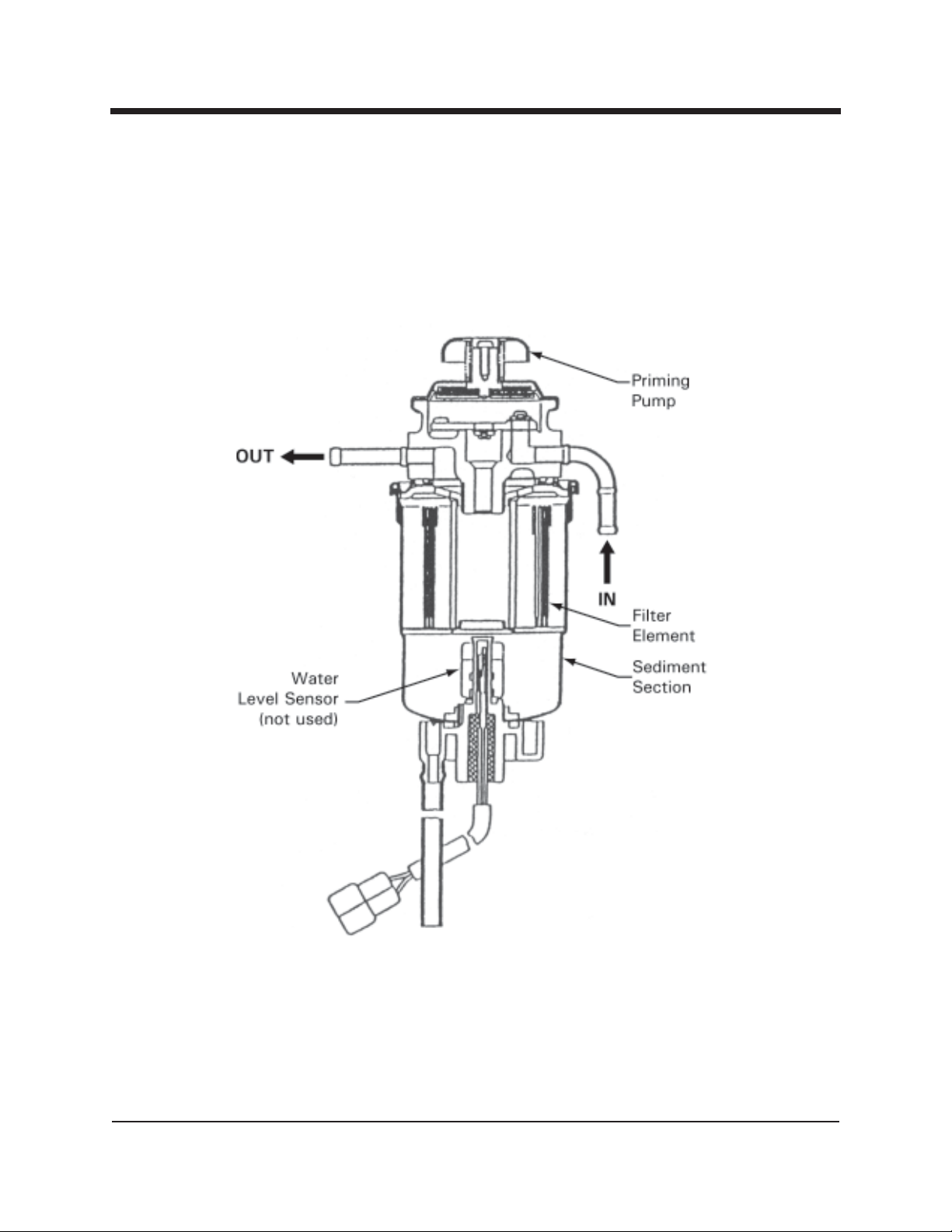
Diesel Fuel Filter with Manual Priming Pump
and Water Separator with Electric Motor.
Quick Reference
HydraMaster Corporation
Page 12
Quick Reference
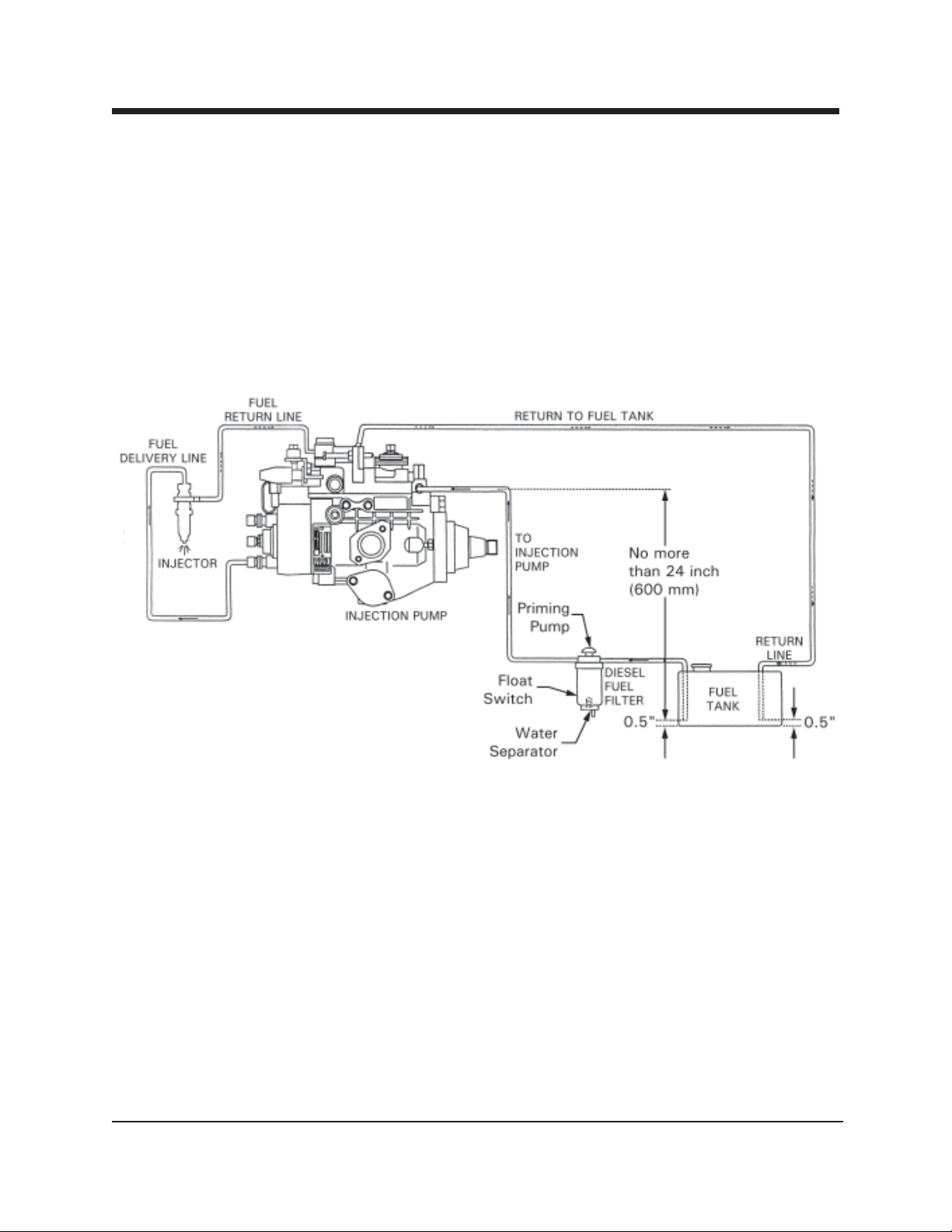
MAXX 450D/470D/450 Diesel
Diesel Fuel Flow Diagram
HydraMaster Corporation
Page 13

Introduction
Maxx 450D/470D/450 Diesel
Section 1-1
his manual contains installation and operation instructions as well as informa-
T
tion required for proper maintenance, adjustment and repair of this unit. Since
the first and most important part of repair work is the correct diagnosis of the
problem, component manual troubleshooting charts have been included for your
convenience.
Unlike a garden tractor, lawn mower or cement mixer, all having one or two functions to perform, the truckmounted carpet cleaning plant has many functions to
perform simultaneously.
• The engine has to run at a consistent RPM.
• The vacuum has to pull air and dirty water back from cleaning site.
• The water pump provides stable pressure at proper water flow for
cleaning.
• The chemical has to be injected into the water stream at the right
concentration.
• The heating system must maintain proper heat.
• The vacuum tank must store dirty water until drained.
As you can see, it is not just a turn-key operation with one thing to worry about,
Does it start?!
HydraMaster Corporation
Page 14

Page 1-2 MAXX 450D/470D/Diesel
!
WARNING
The manufacturer uses this symbol throughout the manual to warn of possible
injury or death
!
CAUTION
This symbol is used to warn of possible equipment damage.
Hours Telephone Numbers
Monday - Friday (425) 775-7276 Parts
8:00 am to 5:00 pm (425) 775-7275 Service
PACIFIC STANDARD TIME (800) 426-4225 Parts/Service Fax
HydraMaster Corporation
Page 15

MAXX 450D/470D/Diesel Page 1-3
Precautions
lthough this unit has been factory adjusted, it may require additional adjust-
A
ments to achieve optimum performance, for instance altitude may require
carburetor adjustment and ambient temperatures may require heat control adjustment. When required, consult an authorized representative.
!
CAUTION
THROUGH-FLOOR DRILLING: Be cautious when drilling holes through the van floor.
Many vans have critical components mounted directly below the van floor that
could be damaged by a misplaced drill bit. (See Product Support Bulletins 92102,
94062 and 94063 at the end of the manual.)
!
CAUTION
ENGINE COOLING: Units employing internal combustion engines must not be
enclosed within a van with doors and windows closed. Excessive temperatures within
the engine will result in premature engine failure and a compromise of
applicable warranty.
!
WARNING
LEVEL OPERATION: During operation, van or trailer must be parked on level ground
not to exceed + or - 10 degrees. Failure to insure proper leveling may prevent
proper internal lubrication of engine, vacuum and/or high pressure components.
!
CAUTION
MOVING PARTS: Never touch any part of the machine that is in motion. Severe
bodily injury may result.
HydraMaster Corporation
Page 16

Page 1-4 MAXX 450D/470D/Diesel
!
CAUTION
ACID RINSE AGENTS: The increased demand for “clear water” rinsing results in
the need for special care when using these acid based chemicals in your equipment.
The negative side of these products is the corrosive effects the acid can have on
metals, including swivels, pumps, heat exchangers, etc.
HydraMaster will not warranty parts that have been damaged from using unprotected acid products that have obviously caused failures.
!
CAUTION
HARD WATER PROTECTION: Failure to take appropriate measures to prevent scale
build up can result in system failure and loss of warranty on affected parts. Test
the water in your immediate and surrounding areas with hard water test strips.
Assume all water obtained from wells is hard. If you are operating in a “Hard Water Area” (3.5 grains or more per gallon), use a water softening system.
!
CAUTION
FREEZE PROTECTION: There is often little warning before a cold spell. Therefore,
not protecting this equipment from freezing will result in costly down-time. Placing
an electric heater in the truck or parking the truck indoors will help to insure against
freezing, but should not be the primary method of freeze protection.
!
CAUTION
EXHAUST SYSTEM: Do not allow flammable material (i.e. oil, fuel, plastic or wood
products) to come in contact with the exhaust system.
!
WARNING
HOT SURFACES: During the operation of this equipment, many surfaces on the
machine will become very hot. When near the van for any reason care must be
taken not to touch any hot surface, such as heater, engine, exhaust, etc.
HydraMaster Corporation
Page 17

MAXX 450D/470D/Diesel Page 1-5
!
WARNING
HEARING PROTECTION: The Occupational Safety and Health Administration
(OSHA) recommends the use of hearing protection when a technician is exposed to
an
average of 85 decibels (this is an average of exposure over an 8 hour period). This
equipment can produce 85 decibels to a distance of 10 feet. Please check with
your local state agencies to see if OSHA standards apply to your application.
!
WARNING
NO SMOKING: It is unsafe to smoke in or around the vehicle.
!
WARNING
CARBON MONOXIDE: This unit generates toxic fumes. Position the vehicle so
that the fumes will be directed away from the job site. Do not park where exhaust
fumes can enter a building through open doors, windows, air conditioning units or
kitchen fans.
!
WARNING
TOXIC FUMES: Do not occupy the vehicle when the cleaning equipment is operat-
ing. Toxic fumes may accumulate inside a stationary vehicle.
!
WARNING
ENGINE EXHAUST: The engine exhaust from this product contains chemicals
known to the State of California to cause cancer, birth defects or other reproductive harm.
!
WARNING
CARBURETOR DRAIN: Under no circumstances should the drain in the carburetor
bowl be utilized when the machine is hot.
!
WARNING
PORTABLE GAS TANK: Never operate this machine with a portable gas can inside
the truck. Doing so increases the risk of a fire or explosion.
HydraMaster Corporation
Page 18

Page 1-6 MAXX 450D/470D/Diesel
!
WARNING
PORTABLE PROPANE TANK: Do not use a portable tank inside of the truck or van.
It is dangerous and illegal in most states.
!
WARNING
TRANSPORTATION OF FUEL CONTAINERS: Transportation in a vehicle of any
vented fuel container that presently has or has ever contained a flammable liquid is
strictly forbidden by HydraMaster Corporation and by federal and state regulation.
!
CAUTION
The use of some chemicals through your mobile carpet cleaning plant can seriously
damage the internal plumbing, high-pressure pump, chemical pump and heat exchangers. These harmful chemicals include concentrated acid (see the pH chart at
the end of this section), solvents (including d-Limonene), and some paint, oil and
grease removers with a high concentration of solvents.
HydraMaster Corporation
Page 19

MAXX 450D/470D/Diesel Page 1-7
System Operation
he MAXX heat exchanger system is a highly engineered cleaning plant designed
T
by HydraMaster Corporation. The system utilizes a dynamic heating system
comprised of three separate heat exchangers for capturing “free heat”.
The water flow is as follows:
Water is fed into the machine under tap pressure to the water box.
The water is then picked up by the high pressure pump and pressurized to the
desired level. The water then splits flow, as demanded by the technician.
The majority of the water flows to the bypass valve assembly, then back
through the blower exhaust heat exchanger, and back to the water box. The
water demanded by the technician flows from the water pump, through the
engine coolant heat exchangers, then through the engine exhaust heat
exchanger and out to the cleaning tool.
When the cleaning solution reaches a preset high temperature, it activates the
exhaust diverter valve control, which prevents the exhaust gases from entering
the exhaust heat exchanger. Once the solution temperature falls below the set
point, the exhaust diverter valve activates to allow the exhaust gases to flow back
through the exhaust heat exchanger. If the exhaust diverter valve becomes inoperable for any reason, the high pressure solenoid valve is activated to release the
heated water from the system and is directed to the recovery tank. Then cool
water enters the
system to regulate the temperature.
As there is no guess work in the manufacture of these highly advanced cleaning
plants, there must be none in preparing it to get the job done in the field. It is the
purpose of this manual to help you properly understand, maintain and service your
cleaning plant. Follow the directions carefully and you will be rewarded with years
of profitable, trouble-free operation.
It is imperative that no section be overlooked when preparing for operation of this
equipment.
HydraMaster Corporation
Page 20

Page 1-8 MAXX 450D/470D/Diesel
Machine Specifications
Frame: 24.5"W x 47.75"L x 37.375"H
Weight: 600 lbs.
Cowling: Aluminum with Epoxy finish
Engine: Daihatsu Liquid Cooled 3 Cylinder, Cast Iron Block, Diesel as required.
Displacement: (450D) 697cc, (470D) 950cc, (Diesel) 850cc
Ignition: Electronically Triggered Coils (1 per cyl.)
12 v Electric Starter Motor
12 v, 40 amp Alternator, Regulated
Electronic Governor
Pressurized Oil System with Filter
Pressurized Cooling System
Triple Row Radiator
Vacuum Blower: Proprietary Dual Shaft Roots
(450D, Diesel) 45 RAI J WhispAir™, (470D) 47 RAI J WhispAir™
Chemical System: High Pressure Injected, Meter Controlled
Heating System: 1 Stainless Steel Coil Exhaust Heat Exchanger
2 Water-to-Water Copper Shell and Tube Heat
Exchangers: 1 Air-to-Water Copper Shell and Tube Heat Exchangers
Instruments and Controls: Water Pressure Gauge, Liquid Filled, 0-1500 PSI
Water Temperature Gauge, 0-250°F
Vacuum Level Gauge, 0-30" Hg
Hour Meter, Machine Run Time
Chemical Flowmeter, Clear Acrylic, 0-10 GPH
Chemical Metering Valve
Chemical Selector Valve
Heat Bypass Lamp
Overheat Protection Lamp
Overheat Shutdown Lamp
Overheat Engine Lamp
HydraMaster Corporation
Page 21

MAXX 450D/470D/Diesel Page 1-9
Instruments and Controls (cont.):
Engine Charging Lamp
Engine Oil Pressure Lamp
Engine Diagnostic Lamp
Pump Out Operating Lamp
“Vacuum Tank Full” Lamp
“Water Supply Low” Lamp
Keyed Ignition
Circuit Breakers Panel
Accessory Switches
Electronic Three Speed Engine Throttle
Mix Tank Drain Valve
Recovery Tank Drain Valve
Panel Mounted Pressure Adjustment Valve
Electric Engine Choke
Diverter Valve Control Switch
Blower Lubrication Port
Recovery Tank: 100 gallon Aluminum, Epoxy Finish
Cleaning Wand: Stainless Steel
—Grip and Replaceable Vacuum Lips with
Stainless Steel Solution Valve.
High Pressure Hose: ¼” High Temperature, Lined, Vinyl Covered
Hose rated to 2200 PSI, 250° F.
Vacuum Hose: 2" Reinforced, 1½” Reinforced
Standard Equipment: Machine Power Console
Full Instrumentation
WhispAirTM Vacuum Blower
MAXX™ Water Heating Package
Vacuum Recovery Tank
Carpet Cleaning Wand
5 gallon Chemical Jug
Chemical Jug Holder
Chemical Jug Fill Line
150 ft, 2" Vacuum Hose
10 ft, 1½” Wand Whip-line
10 ft, 1½” Recovery Drain Line
HydraMaster Corporation
Page 22

Page 1-10 MAXX 450D/470D/Diesel
Standard Equipment: 50 ft, Water Supply Line
150 ft, ¼” Solution Line
Dual-Wand Vacuum Fittings
Dual-Wand Solution Fittings
Battery Box with Holder
Van Decal Package
Van Installation Kit
Operation Manual
HydraMaster Jacket
Optional Equipment: Please refer to Section 14.
HydraMaster Corporation
Page 23

MAXX 450D/470D/Diesel Page 1-11
Spare Parts
own-time on the unit can be very expensive, because your truckmounted unit
D
mize such down-time, it is strongly recommended by the manufacturer that you
purchase and keep in your truck the parts listed below.
Parts Orders
To expedite your parts needs, please call your sales representative. In most instances, he either stocks or has access to parts through a regional service center.
If further assistance is needed, contact the factory and coordinate your needs. If
this becomes necessary, always indicate the method of shipment you desire, i.e.
UPS, Blue Label, Air Freight, Air Express, etc.
is capable of generating several hundred dollars per day. In order to mini-
HydraMaster Parts Dept. Phone ................. (425) 775-7276
HydraMaster Parts Dept. Toll Free Fax ........ 1-800-426-4225
Spare Parts List (078-330)
PART NO DESCRIPTION QTY
010-056 Belt, 4L230 Air Pump Drive (450D Only) 1
010-057 Belt, A28 APO Drive 1
010-059 Belt, A24 Air Pump Drive (470D Only) 1
010-061 Belt, A44 Pump Drive 1
010-080 Belt, BX40 Eng. Drive 2
010-110 Belt, XL7390, Air Pump Gate (450D only) 1
010-115 Belt, XL7395, Air Pump Gate (470D only) 1
056-007 Fuse, 10 amp Circuit 2
056-008 Fuse, 15 amp Circuit 1
046-010 Diaphragm 1
049-002 Fuel Filter 1
049-013 Filter, 3” Stainless Steel Vacuum Pump 1
049-014 Filter, Oil - Daihatsu 1
049-016 Filter, 4“ ‘Y’ 1
049-118 Filter, ¼" Chemical Filter 1
HydraMaster Corporation
Page 24

Page 1-12 MAXX 450D/470D/Diesel
Spare Parts List (078-330 cont.)
PART NO DESCRIPTION QTY
049-023 Screen, Garden Hose 1
049-063 Filter, Air - Daiahtsu 1
049-068 Fuel Separator (450 Diesel Only) 1
052-050 Quick Connect, 440 Male 3
052-051 Quick Connect, 440 Female 2
052-052 Quick Connect, 660 Male 1
052-053 Quick Connect, 660 Female 1
056-010 Fuse, 25 amp. 1
074-032 Meter, Chemical Flow 1
078-019 Kit, H/M Solution Valve 1
078-273 Kit, Bypass Valve Repair 1
157-040 Switch, 12V DC Lighted, ON/OFF 1
157-080 Switch, s/s Float 1
157-131 Switch, 12V DC, Lighted ON/OFF/ON 1
157-008 Switch, Ignition 1
157-022 Switch, Relay 2
169-022 Valve, 1½" Full Port 1
169-155 Valves, Check 2
169-160 2-way Valve 1
169-017 3-way Valve 1
180-004 Orifice, Primary 1
180-006 Orifice, Secondary 1
NOTE:
Engine Oil: 30 weight motor oil with a minimum standard of SE, SF, SG.
Blower OIl: 40 weight non detergent
Pump Oil: 40 weight non-detergent
HydraMaster Corporation
Page 25

MAXX 450D/470D/Diesel Page 1-13
Responsibilities
!
CAUTION
Purchase heavy duty 42 - 60 amp hour battery and have the battery ‘slow’ charge
if new. If the battery is not fully charged, damage can occur to the engine charging
regulator.
Reading of Owner’s Manual: It is the purchaser’s responsibility to read the unit
operation manual and to familiarize himself with the information contained therein.
Special attention should be paid to all Cautions and Warnings.
The Sales Representative’s responsibilities are:
ACCEPTANCE OF SHIPMENT:
1. If the unit shows any outward signs of damage, do not sign the delivery
receipt until you have closely inspected the unit and noted any damage
on the delivery receipt.
2. The salesman from whom you purchased your unit is responsible for
supervising the correct installation of the unit in your vehicle and
thoroughly training you in its operation, maintenance and precautions.
Correct Installation Includes:
• Installation of through-floor fittings for gasoline fuel lines
• Placing the unit and recovery tank in your vehicle and securing them
with bolts or tie down cleats
• Install and connect the fuel pump.
• Connecting gasoline lines
HydraMaster Corporation
Page 26

Page 1-14 MAXX 450D/470D/Diesel
Correct Installation (cont.)
• Connecting the battery
• Checking the pump, vacuum blower and engine oil levels prior to
starting the unit
• Starting the unit to check engine and see that all systems function
normally
• Checking all hoses, wands, etc. for correct operation.
NOTE: Under certain circumstances, machines may require modification for
optimal performance. Cerain environmental conditions may require engine
modification or control function calibration.
Training Shall Include:
• A thorough review of the operation manual with purchaser;
• Instruction and familiarization in:
1. How to correctly start up and shut down the unit
2. How to correctly clean with the unit
3. Where and how often to check and change component oil levels
4. How the unit’s systems work
5. How to troubleshoot the unit
6. How to do basic repairs
7. Safety precautions and their importance
8. Freezing damage and how to avoid it
9. Hard water damage and how to avoid it
10. Cleaning the orifices and how they function in the system
• A thorough review of the unit warranty and warranty procedures.
• A thorough review of hard water precautions and warnings.
• How to determine hard water areas.
• Use of water softening systems.
HydraMaster Corporation
Page 27
MAXX 450D/470D/Diesel Page 1-15
Vehicle Preparation
hen selecting a truck, remember the preferable vehicle for a Boxxer 421
W
ton capacity. If a fresh water tank is added, a three quarter ton or larger capacity
van, with a 2,400 pound payload capacity, is required.
TRUCK PREPARATION
The manufacturer recommends the installation of a spray-on bed liner in the vehicle prior to installation of machine.
installation is a cargo van with a heavy-duty suspension package and a half
!
CAUTION
Be cautious when drilling any holes through the van floor. Many vans have
critical components mounted directly below the van floor that could be
damaged by a misplaced drill bit. (See Product Support Bulletins 92101,
94062, and 94063 at the end of this manual.)
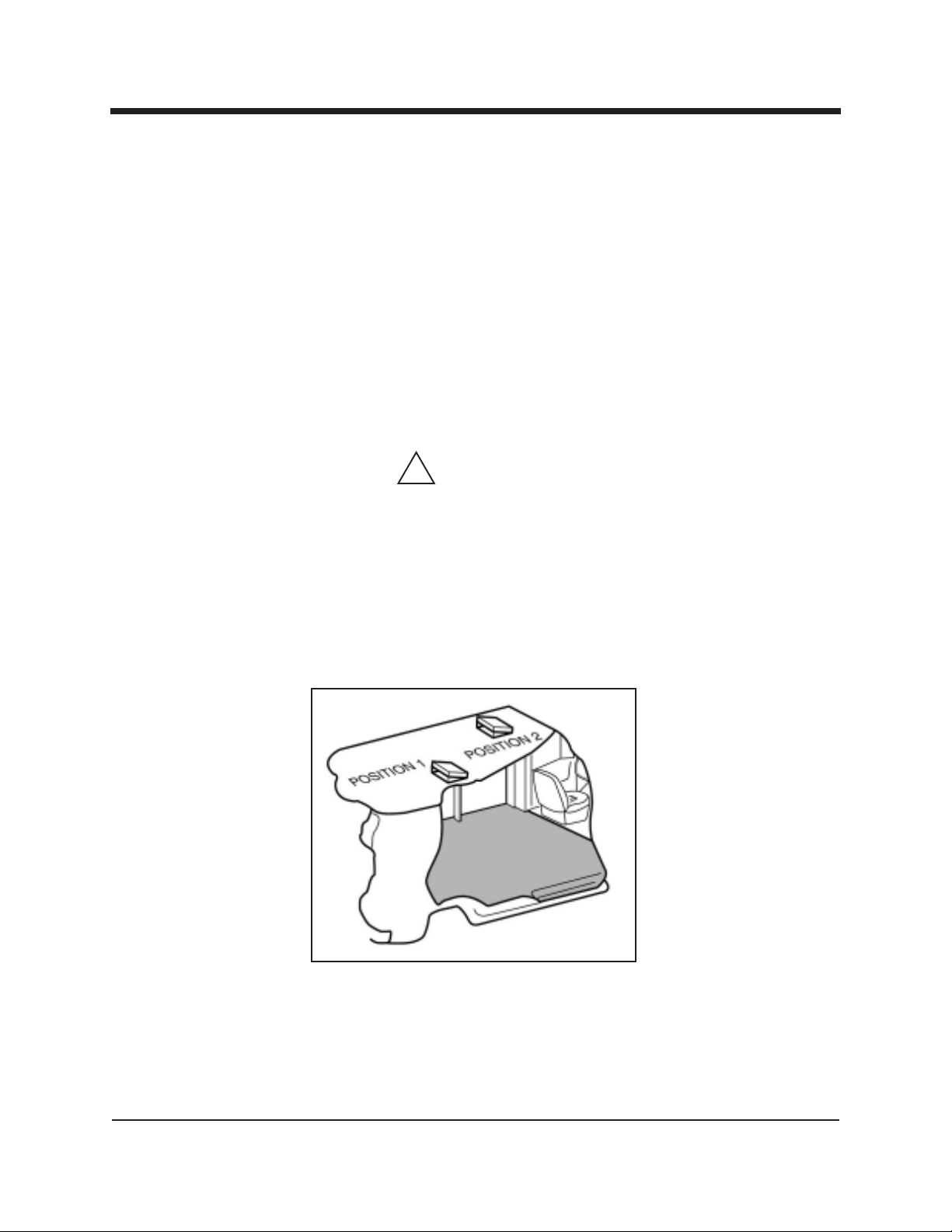
This provides ‘metal to cushion’ mounting rather than ‘metal to metal’ and makes
for an attractive van interior. It is highly recommended to install roof vents in
vehicles operated in hot weather locations. Roof vent positions are shown in
Figure 1-1.
Figure 1-1 Roof Vent
HydraMaster Corporation
Page 28
Page 1-16 MAXX 450D/470D/Diesel
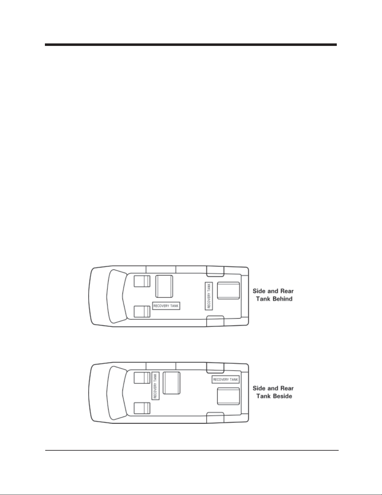
PLACEMENT OF UNIT IN VEHICLE
There are two recommended unit placements:
SIDE DOOR:
Most installations are side door. This provides rear access for accessories and
hoses as well as unobstructed access to the component/working side of the
machine, thus making it a bit easier to perform maintenance and/or repair without
removing the unit from the truck.
REAR DOOR:
Although this location partly limits working access, it does direct the noise away
from the cleaning site. Some cleaners in the colder areas prefer this location because it puts the weight over the rear wheels for better traction in ice and snow.
Rear mounting requires the unit to be slid to the right side as far as possible.
This not only provides adequate working space on the component side of the unit but
also improves weight distribution inside the van (engine and component weight line
up over drive shaft). Also, it is physically easier to load the unit into the rear door
due to the height of the van bed.
Figure 1-2 Recommended Placement
HydraMaster Corporation
Page 29
MAXX 450D/470D/Diesel Page 1-17
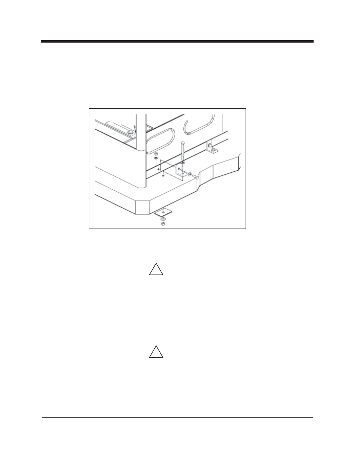
Machine Tie Down Cleats
Secure the machine to the floor of the van with the four tie down cleats provided.
This safety measure will ensure that the machine will not slide inside the van. See
the following illustration for the correct installation.
Figure 1-3 Installation Using Tie-down Cleats
Ensure that the machine is well secured to the floor of the van with the hardware
supplied. A sudden or crash stop will cause the machine to rocket forward. Protect yourself and the machine. SECURE IT!
!
WARNING
It is recommended by the manufacturer that the exhaust from the front of
the machine be vented down under the truck to prevent carbon monoxide
from entering the job site. Always park the truck so the exhaust is blowing
away from the job site.
The manufacturer also recommends the installation of aluminum vents in the
truck roof to allow heat to escape.
!
WARNING
Never operate this machine with a portable gas can inside the truck. Doing
so increases the risk of a fire or explosion.
Mount a fire extinguisher just inside the rear or side door for emergencies.
HydraMaster Corporation
Page 30

Page 1-18 MAXX 450D/470D/Diesel
!
WARNING
Do not use a portable propane tank inside of the truck or van. It is dangerous and illegal in most states.
!
WARNING
Transportation in a vehicle of any vented fuel container that presently holds
or has ever held a flammable liquid is strictly forbidden by HydraMaster
Corporation and by federal and state regulation.
!
WARNING
The engine exhaust from this product contains chemicals known to the
State of California to cause cancer, birth defects or other reproductive
harm.
HydraMaster Corporation
Page 31

MAXX 450D/470D/Diesel Page 1-19
High Altitude Operation
Preparation
o have your machine run at it’s peak performance; you may have to make adjust
ments depending on the elevation. Elevation plays a key role in how the machine
T
will operate.
The factory setting of the machine is set for elevations from 0—3,000 feet. Any
time the machine is operated above 3,000 feet there are two areas on the machine
the may need adjustment.
The first area is the carburetor jet. The higher the elevation, the less air is provided to the fuel mixture. This will make the engine run ‘rich’, and, in turn will
result in the loss of power, excessive heat in the exhaust, and carbon build-up in
the exhaust and heat exchanger system. The jet sizes vary per engine and elevation. Consult HydraMaster to obtain proper jet size.
Carburetor Jet- See chart below for specific jet size.
Maxx 450D/700G Daihatsu Engine Maxx 470D/950G Daihatsu Engine
Altitude P/N BS&D P/N Jet Size Altitude P/N BS&D P/N Jet Size
0-3,000 ft. (Factory Jet) 076-063 825469 #130 0-3,000 ft. (Factory Jet) 076-064 820627 #140
2,400-6,600 ft. 076-060 820457 #120 2,400-6,600 ft. 076-065 825470 #132
6,000-10,000 ft. 076-062 825471 #112 6,000-10,000 ft 076-061 825291 #126
The second area that may need adjustment is the heat control system. The heat
control system is also optimized to 0-3,000 feet. At highter altitudes the boiling
point of water is lowered. In turn, this can cause the water box to boil and the
high pressure pump to cavitate. The heat control system settings will have to be
adjusted to compensate for the elevation. These settings will vary according to
elevation. Contact HydraMaster to obtain the recommended settings.
Thermal Relief Valve - Change from180°F to 165° F. Order Part No. 000-169027 - 165° F Thermal Relief Valve.
HydraMaster Corporation
Page 32

Page 1-20 MAXX 450D/470D/Diesel
Diverter Valve - Machines that are equipped with a diverter valve may need adjustment after the machine has been installed.
Prior to running the machine, perform the following steps:
1) Locate the actuator connected to the
diverter valve arm which is at the top
left of the machine U-bracket, near the
rear of the machine. See Figure 1-4.
2) The actuator shaft is connected to the
diverter valve arm. Pull the actuator
shaft forward and listen to hear if the
poppet seals against the seat in the
diverter valve. Push the actuator shaft
back and listen to see if the poppet seals
against the seat in the diverter valve.
If the poppet seats in both directions, the the diverter actuator is in proper
adjustment.
If the poppet does not seat in one or both directions the valve is out of
adjustment. Perform the following steps to adjust the diverter actuator
shaft.
3) The end of the actuator shaft is threaded into the diverter arm and is
secured into position with a back-up nut. This nut must be loosened to
allow adjustment.
Figure 1-4 Actuator Location
4) Loosen the actuator back-up nut. This will allow you to rotate the
actuator shaft clockwise or counter-clockwise. Rotate the actuator shaft
one half turn at a time. Then pull the actuator shaft forward and back.
Listen to hear if the poppet seals in the seat of the diverter valve. Repeat
this step until the diverter poppet seals in both directions. See Figure 1.
5) Apply red Loctite on the thread of the actuator shaft. Re-tighten the
back-up nut.
6) Recheck the adjustment. Move the actuator shaft forward and back.
Listen to hear if the diverter poppet seals in both directions.
The diverter is now properly adjusted.
HydraMaster Corporation
Page 33

MAXX 450D/470D/Diesel Page 1-21
Local Water Precautions
he quality of water varies greatly. Many areas have an excess of minerals in
T
the water which results in what is commonly called “hard water.” These minerals tend to adhere to the insides of heater coils and other parts of the machines
causing damage and a loss of cleaning effectiveness. This influences the reliability
and efficiency of equipment in direct proportion to the level of hardness.
HARD WATER ADVISORY
HydraMaster recognizes that any hard water deposits which might occur within the
water system of our truckmounts is a serious problem. The precision technology of
truckmount heat exchanger systems is intolerant of any foreign material. Hard water
deposits will ultimately decrease the performance of the system and are expected to
seriously lower the reliability of the machine.
To validate a machine’s warranty, HydraMaster requires that all machines operating in
designated “Hard Water Areas” (3.5 grains or more per gallon) be fitted with a water
softening system or a properly installed magnetic-type de-scaler must be used and
maintained. Periodic de-scaling or acid-rinsing alone is not adequate in these areas.
HydraMaster does not recommend any particular type or brand, however the relative
effectiveness of some types of magnetic de-scalers or softeners may require additional periodic use of de-scaling agents.
HydraMaster also recommends, in the strongest possible terms, that machines in all
areas be fitted with a water softening system for improved operation and reliability.
HydraMaster has included five hard water test strips with your machine. These can
be used to test the water in your immediate and surrounding areas as they can vary
greatly. Assume all water obtained from wells is hard.
!
CAUTION
Failure to take appropriate measures to prevent scale build up can result in system
failure and loss of warranty on affected parts.
HydraMaster Corporation
Page 34

Page 1-22 MAXX 450D/470D/Diesel
HARD WATER AREA MAP
The following map defines areas in the United States which compromise fluid
related components such as hoses, fittings, heaters, pumps, valves and water cooled
engines. For other countries, hard water area maps can be obtained from geological
societies.
WATER SOFTENER
Cleaning efficiency and equipment life is increased, chemical use decreased, and
the appearance of cleaned carpets enhanced when water softeners are incorporated
in hard water areas. The manufacturer strongly urges the use of water softener
units in areas exceeding 3½ grains per gallon. Failure to use a water softener in
these areas will invalidate the machine’s warranty. Using a Hard Water Area map
as a reference, determine the quality of water in your area and take action immediately, if necessary.
Reports from several of our machine users commending the results of the use of
water softeners in conjunction with their machines prompts us to recommend the
procedure to everyone in a “hard water” area.
The relatively low cost of a water softener service is more than made up for by an
increased life of machine parts, reduced chemical costs and continued cleaning
efficiency. The water softener will also increase the effectiveness of the cleaning
chemicals, therefore less chemical will be needed.
Contact a water softener distributor in your area for information on the rental of a
simple water treatment unit to carry in your truck. Be sure to change the water
softener in accordance with the capability of the softener. For example: If the
softener will treat 900 gallons of water and the machine uses an average of 30
gallons per hour, for an average of 5 hours a day, this equals 150 gallons per day.
In 6 days the machine would use 900 gallons of water. Therefore, the softener
would need to be changed every 6 working days for maximum softening.
WASTE WATER DISPOSAL ADVISORY
There are laws in most communities prohibiting the dumping of recovered “gray”
water from carpet cleaning in any place but a sanitary treatment system.
HydraMaster Corporation
Page 35

MAXX 450D/470D/Diesel Page 1-23
Waste Water Disposal Advisor (cont.)
This cleaning rinse water, recovered into your unit’s vacuum tank, contains
materials such as detergents. These must be processed before being safe for streams,
rivers and reservoirs.
IN ACCORDANCE WITH THE EPA, STATE AND LOCAL LAWS, DO NOT DISPOSE
OF WASTE WATER INTO GUTTERS, STORM DRAINS, STREAMS, RESERVOIRS,
ETC.
In most cases, an acceptable method of waste water disposal is to discharge into a
municipal sewage treatment system after first filtering out solid material such as
carpet fiber. Access to the sanitary system can be obtained through a toilet, laundry drain, RV dump, etc. Permission should first be obtained from any concerned
party or agency.
One disposal method which usually complies with the law is to accumulate the waste
water and haul it to an appropriate dump site. Another solution to the disposal
problem is to equip yourself with an Automatic Pump-Out System (APO). These
systems are designed to remove waste water from the extractor’s recovery system
and actively pump the water through hoses to a suitable disposal drain. Properly
designed, they will continuously monitor the level of waste water and pump it out
simultaneously to the cleaning operation. The hidden benefit of this process is that
the technician does not have to stop his cleaning to empty the recovery tank.
HydraMaster makes an APO system available which can be ordered with new equipment or installed later.
The penalties for noncompliance can be serious. Always check local laws and
regulations to be sure you are in compliance.
HydraMaster Corporation
11/21/00
Page 36

Page 1-24 MAXX 450D/470D/Diesel
This page intentionally left blank
HydraMaster Corporation
Page 37

MAXX 450D/470/Diesel Page 1-25
Machine Assemblies
and Parts Lists
This section will be revised as drawings become available
HydraMaster Corporation
Page 38

Page 1-26 MAXX 450D/470/Diesel
Figure 1-7 Maxx 450D/470D Frame Assembly - View 1
D-4355 Rev F
33
35
13
18
19
43
HIDDEN
HIDDEN
HIDDEN
HIDDEN
47
4
6
45
6
44
30
49
48
20
8
23
20
25
47
16
3
DIESEL ONLY
17
28
26
17
32
31
32
18
30
10
34
27
34
28
26
40
39
8
41
42
27
28
24
HydraMaster Corporation
Page 39

MAXX 450D/470/Diesel Page 1-27
Figure 1-8 Maxx 450D/470D Frame Assembly - View 2
D-4355 Rev F
37
15
33
35
2
5
38
36
14
14
10
11
12
29
13
8
10
24
27
26
25
24
28
17
30
18
46
50
6
9
10
24
25
26
HydraMaster Corporation
7
22
21
7
32
31
31
30
48
27
24
30
48
10
31
1
Page 40

Page 1-28 MAXX 450D/470/Diesel
Frame Assembly Parts List
Item Part Number Description Qty
1 000-055-155 Frame, Final Stock - Maxx 450D/470D 1
2 000-055-138 Frame, Engine Cover - Maxx 450D/470D 1
3 000-015-600 Bracket, Heat Exchanger Mount 1
4 000-015-629 Bracket, After Burner Mounting Saddle 1
5 000-033-115 Clamp, After Burner Mount 2
6 000-143-096 Screw, 3/8"-16UNC x 1.00" Lg. Hex Head 8
7 000-106-003 Plug, 3/8" NPT Hex 2
8 000-174-032 Washer, 3/8" Flat 7
9 000-094-015 Nut, 3/8"-16UNC Hex 2-Way Locking 4
10 000-143-012 Screw, 5/16"-18UNC x 0.75" Lg. Hex Head 12
11 000-174-018 Washer, 5/16" Lock 4
12 000-174-049 Washer, 5/16" Flat 4
13 000-143-001 Screw, 1/4"-20UNC x 0.75" Lg. Hex Head 2
14 000-094-010 Nut, 1/4"-20UNC Hex 4
15 000-108-115 Protector, 5/8" Bumper 12
16 000-060-010 Grommet, 1-5/16" I.D. 1
17 000-060-002 Grommet, Large Wiring 5
18 000-174-014 Washer, #10 Lock 4
19 000-143-327 Screw, #10-32UNF x 0.50" Lg. Hex Head 2
20 000-052-104 Insert, #66 (3/8" NPT x 3/8" Barb) 2
21 000-052-427 Bushing, 1/8" NPT x 1/8" FPT 1
22 000-106-001 Plug, 1/8" NPT 1
23 000-052-109 Insert, #F24 (1/8" NPT x 1/4" Barb) 1
24 000-033-119 Clamping Unit, HC-10-2-3, 2 Position 6
25 000-020-041 Bushing, Split, G-10-8 Clamping Unit 3
26 000-020-042 Bushing, Split, G-10-8 Clamping Unit 4
27 000-094-104 Nut, Stacking, N-10 Clamping Unit 8
28 000-143-199 Screw, Thread Adapter T-10, Clamping Unit 6
29 000-033-053 Clamp, 1-1/2" Cushion Loop 1
30 000-174-001 Washer, #10 Flat 5
HydraMaster Corporation
Page 41

MAXX 450D/470/Diesel Page 1-29
Frame Assembly Parts List
Item Part Number Description Qty
31 000-143-126 Screw, #10-24UNC x 0.50" Lg. Hex Head 4
32 000-033-044 Clamp, 3/8" Tube 3
33 000-094-009 Nut, 1/4"-20UNC Hex Nylock 2
34 000-033-120 Clamping Unit, HC-10-1 Single Position Unit 2
35 000-174-003 Washer, 1/4" Flat 2
36 000-141-033 Rod, Heat Exchanger Strap - Retainer 2
37 Fig. 1-24 Assembly, Diverter Valve Actuator - Maxx 450D/470D 1
38 000-143-004 Screw, 1/4"-20UNC x 1.50" Lg. Hex Head 2
39 000-174-021 Washer, 3/8" Lock 2
40 000-143-017 Screw, 3/8"-16UNC x 0.75" Lg. Hex Head Grd. 8 2
41 000-143-025 Screw, 3/8"-16UNC x 1.25" Lg. Hex Head Grd 8 1
42 000-094-100 Nut, 3/8"-16UNC Hex Nylock 1
43 Fig. 1-18 Assembly, Water Box - Poly - Maxx 1
44 000-174-004 Washer, 5/16" Flat 4
45 000-174-057 Washer, 3/8" Lock 4
46 000-105-012 Plate, Machine Serial I.D. 1
47 000-027-034 Cap, Frame End - Modified - Maxx/CTS 450 2
48 000-033-057 Clamp, 1" Cushion Loop 3
49 000-094-034 Nut, #10-24UNC Nylock 1
50 000-140-001 Rivet, 1/8" x 1/4" Aluminum 2
HydraMaster Corporation
Page 42

Page 1-30 MAXX 450D/470/Diesel
Figure 1-9 100 Gallon Universal Recovery Tank Assembly
D-6984 Rev -
12
11
HIDDEN
HIDDEN
HIDDEN
HIDDEN
2
28
19
20
9
7
29
32
20
31
5
35
20
19
49
35
47
35
50
19
20
49
6
29
25
26
15
HIDDEN
HIDDEN
18
30
13
16
17
8
14
46
44
37
36
40
26
38
39
43
42
31
33
4
21
45
27
10
34
HIDDEN
30
HIDDEN
13
3
491920
HIDDEN
34
30
HIDDEN
35
48
24 23 22
41
10
13
3
1
HydraMaster Corporation
Page 43

MAXX 450D/470/Diesel Page 1-31
100 Gallon Universal Recovery Tank Assembly Parts List
Item Part Number Description Qty
1 000-159-129 Tank, 100 Gallon Universal Recovery - Weldment 1
2 Fig. 1-10 Assembly, Recovery Tank Cover - 100 Gallon 1
3 000-157-090 Float, Lever Switch 2
4 000-079-091 Kit, Dura-Flow APO - Production (Fig. 1-22) 1
5 000-105-336 Plate, Vacuum Port Cover - 100 Gallon Universal Recovery T 1
6 000-049-152 Filter, Recovery Tank Basket 1
7 000-049-153 Filter, Flat - Recovery Tank 1
8 000-012-002 Block, 6 Post Terminal 1
9 000-015-932 Bracket, Flat Filter Securing - Universal Recovery Tank 1
10 000-033-023 Clamp, 3/4" Nylon Hose 2
11 000-049-154 Deflector, Air - Univeral Recovery Tank 1
12 000-140-023 Rivet, AB8-6A Aluminum Pop 6
13 000-143-126 Screw, #10-24UNC x 0.50" Lg. Hex Head 5
14 000-143-051 Screw, #8-32UNC x 0.75" Lg. Binder Head Phillips 2
15 000-094-059 Nut, #8-32UNF Nylock 2
16 000-086-008 Latch, Bungie 1
17 000-143-539 Screw, #6-32UNC x 0.50" Lg. Button Head Allen 2
18 000-094-063 Nut, #6-32UNC Nylock 2
19 000-174-019 Washer, 1/4" Lock 14
20 000-174-003 Washer, 1/4" Flat 22
21 000-106-019 Plug, 1-1/2" NPT 1
22 000-052-763 Nipple, 1-1/2" Ips Close s/s 1
23 000-169-022 Valve, 1-1/2" Full Port Ball 1
24 000-052-226 Insert,1-1/2" NPT x 1-1/2" Barb (Grey) 1
25 000-052-082 Elbow, 1/4" NPT Street x 45° 1
26 000-052-102 Insert, #46 (1/4" NPT x 3/8" Barb) 2
27 000-081-115 Label, Maintenance & Lubrication Schedule 1
28 000-143-333 Screw, 1/4"-20UNC x 0.50" Lg. Hex Head 2
29 000-174-029 Washer, 3/8" Rubber Back 2
30 000-174-036 Washer, #10 Flat Rubber Backed 5
HydraMaster Corporation
Page 44

Page 1-32 MAXX 450D/470/Diesel
100 Gallon Universal Recovery Tank Assembly Parts List
Item Part Number Description Qty
31 000-143-002 Screw, 1/4"-20UNC x 1.00" Lg. Hex Head 8
32 000-094-009 Nut, 1/4"-20UNC Hex Nylock 4
33 000-166-002 Tray, Soap Jug - Weldment 1
34 000-094-034 Nut, #10-24UNC Nylock 2
35 000-057-206 Gasket, Adapter - Universal Recovery Tank 4
36 000-052-085 Elbow, 1/4" NPT Street 1
37 000-052-090 Tee, 1/4" NPT Branch M-F-F 1
38 000-169-082 Valve, 12 Volt Solenoid 1200 PSI 1
39 000-052-662 Nipple, 3/8" NPT x 1/4" M SAE 1
40 000-052-073 Nipple, 3/8" NPT x 1/4" NPT Hex 1
41 000-106-049 Plug, 1" NPT Allen Head 1
42 000-174-060 Washer, 1/4" Flat Rubber Backed 4
43 000-094-113 Nut, 1/4"-20UNC Neoprene Wellnut 4
44 000-052-088 Elbow, 1/4" FPT x FPT 1
45 000-060-002 Grommet, Large Wiring 1
46 000-052-071 Nipple, 1/4" NPT Hex 1
47 000-013-070 Box, Vacuum Relief Valve - Universal Recovery Tank 1
48 Fig. 1-11 Assembly, Vacuum Relief Valve 1
49 000-143-001 Screw, 1/4"-20UNC x 0.75" Lg. Hex Head 12
50 000-001-132 Adapter, Tank To Ø3.0" Blower Hose - Universal Recovery T 1
HydraMaster Corporation
Page 45

MAXX 450D/470/Diesel Page 1-33
Figure 1-10 100 Gallon Universal Recovery Tank Cover Assembly
D-6919 Rev -
8
2
5
6
7
9
1
3
4
10
11
9
100 Gallon Universal Recovery Tank Cover Assembly Parts List
Item Part Number Description Qty
1 000-041-447 Cover, 100 Gallon Universal Recovery Tank - Weldment 1
2 000-078-039 Vacuum Inlet Stopper Assembly - Recovery Tank 1
3 000-057-015 Gasket, 1-1/2" Bulkhead Fitting 2
4 000-052-219 Adapter, 2" NPT x 2" F Slip 2
5 000-143-539 Screw, #6-32UNC x 0.50" Lg. Button Head Allen 2
6 000-086-008 Latch, Bungie - Strike 1
7 000-094-063 Nut, #6-32UNC Nylock 2
8 000-052-222 Elbow, 2" Barb x 2" FPT 2
9 000-057-202 Gasket, End - Recovery Tank 2
10 000-057-203 Gasket, Middle - Recovery Tank 3
11 000-057-205 Gasket, Side - Recovery Tank - 100 Gallon 2
HydraMaster Corporation
Page 46

Page 1-34 MAXX 450D/470/Diesel
Figure 1-11 Vacuum Relief Valve Assembly
C-6894 Rev -
7
5
3
1
4
8 2
6
Vacuum Relief Valve Assembly Parts List
Item Part Number Description Qty
1 000-015-182 Bracket, Vacuum Relief Valve 1
2 000-027-032 Cap, Vacuum Releif Valve 1
3 000-125-111 Pipe, Vacuum Relief Spring Guide 1
4 000-105-332 Plate, Vacuum Relief Valve Mounting - Universal Recovery T 1
5 000-155-026 Spring, Vacuum Relief 1
6 000-143-198 Screw, 3/8"-16UNC x 4" Lg. Hex Head Full Thread 1
7 000-094-077 Nut, 3/8"-16UNC x 1.00" O.D. Knurled 2
8 000-094-101 Nut, 3/8"-16UNC Hex Jam 1
HydraMaster Corporation
Page 47

MAXX 450D/470/Diesel Page 1-35
Figure 1-12 Dash Assembly
D-4359 Rev F
222710
HIDDEN
22
23
28
28
23
22
11
32
16
11
32
13
14
37
16
10
15
25
5
9
30
7
25
15
36
10
35
18
17
29
22
10
34
33
22
16
23
21
1
7
11
8
12
2227 106
20
26
22
24
4
2 22 21
19
24
23
24
223
1
24
BACK DETIAL
HydraMaster Corporation
31
15
Page 48

Page 1-36 MAXX 450D/470/Diesel
Dash Assembly Parts List
Item Part Number Description Qty
1 000-100-088 Panel, Main Dash - Maxx 450D/470D 1
2 000-100-096 Grill, Upper Dash 1
3 Fig. 1-13 Assembly, Lower Dash Plumbing Connection Panel - Maxx 4 1
4 Fig. 1-14 Assembly, Upper Dash Instrument Panel - Maxx 1
5 000-100-102 Panel, Perforated Grill 1
6 Fig. 1-15 Assembly, Control Panel 1
7 000-169-160 Valve, Chemical Metering 1
8 000-169-0171 Valve, 3-Way Ball O-Ring Style 1
9 000-074-030 Meter, Chemical Flow Raw 1
10 000-108-115 Protector, 5/8" Bumper 12
11 000-052-069 Nipple, 1/8" NPT Hex 3
12 000-052-078 Elbow, 1/8" NPT x 45° Street 1
13 000-052-531 Elbow, 1/8" NPT x 1/4" SAE 1
14 000-052-084 Elbow, 1/8" NPT Street 1
15 000-094-034 Nut, #10-24UNC Nylock 7
16 000-052-099 Insert, #26 (1/8" NPT x 3/8" Barb) 3
17 000-025-011 Cable, Choke (5 Foot) 1
18 000-094-098 Nut, 7/16"-24UNF - 2 Way Metering Valve 1
19 000-131-131 Trimlok, 3/8" x 1/8" 1
20 000-105-221 Plate, HydraMaster Name - Maxx 1
21 000-143-171 Screw, #10-24UNC x 1.25" Lg. Hex Head 7
22 000-174-001 Washer, #10 Flat 26
23 000-155-054 Spring, #10 Belleville Washer 10
24 000-143-134 Screw, #10-24UNC x 1.00" Lg Hex Head 11
25 000-174-036 Washer, #10 Flat Rubber Backed 6
26 000-084-013 Reflector 1.25" x 12" Transparent 1
27 000-094-004 Nut, #10-24UNC Hex 2
28 000-143-166 Screw, #10-24UNC x 0.38" Lg. Hex Head 4
29 000-174-030 Washer, 5/8" I.D. x 7/8" O.D. x 0.010" Thk. 1
30 000-174-062 Washer, 1/2" I.D. x 3/4" O.D. x 0.010" Thk. 1
HydraMaster Corporation
Page 49

MAXX 450D/470/Diesel Page 1-37
Dash Assembly Parts List
Item Part Number Description Qty
31 000-033-057 Clamp, 1" Cushion Loop 1
32 000-052-089 Elbow, 1/8" NPT Female 2
33 000-143-328 Screw, #10-32UNF x 1/2" Lg. Phillips Head 2
34 000-174-014 Washer, #10 Lock 2
35 000-174-057 Washer, 3/8" Lock 1
36 000-174-032 Washer, 3/8" Flat 1
37 000-052-530 Nipple, 1/8" MNPT x 1/4" SAE 1
Figure 1-13 Lower Dash Plumbing Connection Panel Assembly
D-4357 Rev D
23
12
14
2
13
18
7
3
9
20
10
5
6
16
17
19
15
16
17
HydraMaster Corporation
19
22
21
8
11
1
24
4
Page 50

Page 1-38 MAXX 450D/470/Diesel
Lower Dash Plumbling Connection Panel Assembly Parts List
Item Part Number Description Qty
1 000-100-094 Panel, Lower Dash Plumbing Connection 1
2 000-090-008 Manifold, Hi Pressure 1
3 Fig. 1-29 Assembly, Hi-PSI Manifold - Maxx 450D/470D 1
4 000-052-052 Quick Connect, 660 Male w/ Viton Standard 1
5 000-052-050 Quick Connect, 440 Male w/ Viton Standard 2
6 000-052-272 Cup, Gravity Feed Oil Blower Lubrication Port 1
7 000-052-086 Elbow, 3/8" NPT Street 1
8 000-052-074 Nipple, 3/8" NPT Hex 1
9 000-174-007 Washer, 1/2" Flat 4
10 000-174-032 Washer, 3/8" Flat 2
11 000-174-008 Washer, 5/8" Flat 1
12 000-052-071 Nipple, 1/4" NPT Hex 2
13 000-052-528 Nipple, 3/8" M JIC x 3/8" NPT 1
14 000-052-532 Elbow, 1/4" SAE x 1/4" JIC x 90° 1
15 000-143-126 Screw, #10-24UNC x 0.50" Lg. Hex Head 2
16 000-143-542 Screw, 1/4"-28UNF x 0.50" Lg. 2
17 000-155-053 Spring, 1/4" Belleville Washer 2
18 000-106-009 Plug, 1/8" NPT Allen Head 1
19 Fig. 1-30 Assembly, By-Pass Valve - Maxx 450DD 1
20 000-052-096 Insert, #F23 (1/8" FPT x 3/16" Barb) 1
21 000-052-142 Elbow, 3/8" FPT x FPT 1
22 000-052-105 Insert, #68 (3/8" NPT x 1/2" Barb) 1
23 000-068-513 Hose, 3/8" x 10" Teflon w/ F JIC End & 3/8" NPT 1
24 000-131-131 Trimlok, 3/8" x 1/8" 1
HydraMaster Corporation
Page 51

MAXX 450D/470/Diesel Page 1-39
Figure 1-14 Upper Dash Instrument Panel Assembly
C-4356 Rev A
15
19
16
17
19
18
20
15
15
14
18
15
11
6
1
7
7
7
1
11
2
13
12
4
5
1
5
5
5
10
3
9
7
8
7
7
HydraMaster Corporation
Page 52

Page 1-40 MAXX 450D/470/Diesel
Upper Dash Instrument Panel Assembly Parts List
Item Part Number Description Qty
1 000-100-092 Panel, Upper Dash Instrument 1
2 000-074-016 Guage, Temperature 1
3 000-074-017 Guage, 0-30" Hg Vac. 2 1/2" HydraMaster Face 1
4 000-157-008 Switch, Ignition 1
5 000-157-040 Switch, 20 AMP Rocker 4
6 000-074-018 Meter, Rectangular w/o Bezel 1
7 000-084-011 Light, Red Led Indicator Mini 6
8 000-084-010 Light, Green Led Indicator Mini 3
9 000-061-056 Knob, Temperature Adjustment 1
10 000-157-131 Switch, 3 Way Speed Control 1
11 000-015-566 Bracket, Upper Dash Instrument Hinge 2
12 000-074-007 Gauge, 2" Dia. 0-1500 PSI 1
13 000-149-047 Thermostat, n/s Temperature Controller 1
14 000-052-088 Elbow, 1/4" FPT x FPT 1
15 000-094-034 Nut, #10-24UNC Nylock 4
16 000-052-527 Nipple, 1/4" SAE x 1/4" NPT 1
17 000-052-652 Insert, #F42 (1/4" FPT x 1/8" Barb) 1
18 000-174-001 Washer, #10 Flat 4
19 000-094-070 Nut, 5mm Nylock 4
20 000-131-131 Trimlok, 3/8" x 1/8" 1
HydraMaster Corporation
Page 53

MAXX 450D/470/Diesel Page 1-41
Figure 1-15 Electrical Control Panel Assembly
D-4548 Rev E
13
1210
14
16
7
17
16
8
12
18
19
12
22
23
12
10
13
12 12
1315 511
5
159 6
11
3 11
11
5
12
21
20
14
2
14
HIDDEN
1
HydraMaster Corporation
Page 54

Page 1-42 MAXX 450D/470/Diesel
Electrical Control Panel Assembly Parts List
Item Part Number Description Qty
1 000-100-100 Panel, Control Mount 1
2 000-074-110 Controller, Temp. Analog 1
3 000-012-010 Block, Terminal 10 Post 2
4 000-084-009 Lamp, Socket - Dashboard 4
5 000-084-004 Lamp, Replacement Guage 4
6 000-060-010 Grommet, 1-5/16" I.D. 2
7 000-056-020 Fuse Panel 1
8 000-056-030 Diode Panel 1
9 000-018-040 Circuit Breaker, 50 AMP 1
10 000-157-022 Switch, Relay 3
11 000-143-062 Screw, #10-24UNC x 0.75" Lg. Pan Head Phillips 4
12 000-094-034 Nut, #10-24UNC Nylock 10
13 000-143-166 Screw, #10-24UNC x 0.38" Lg. Hex Head 3
14 000-143-545 Screw, #8-32UNC x 1.00" Lg. Phillips Head 9
15 000-143-533 Screw, #10-24UNC x 0.25" Lg. Pan Head Phillips 2
16 000-174-014 Washer, #10 Lock 10
17 000-143-298 Screw, #8-32UNC x 1.50" Lg. Pan Head Phillips 1
18 000-033-044 Clamp, 3/8" Tube 1
19 000-143-126 Screw, #10-24UNC x 0.50" Lg. Hex Head 1
20 000-072-010 Ignition Processor - 700G Daihatsu 1
21 000-072-009 Ignition Processor - 950G Daihatsu 1
22 000-029-016 Governor, Hall Affects Maxx 450D/470DD 1
23 000-029-030 Governor, Magnetic Pick Up - Maxx Diesel 1
HydraMaster Corporation
Page 55

MAXX 450D/470/Diesel Page 1-43
Figure 1-16 Bypass Heat Exchanger
C-4587 Rev C
4
5
4
2
3
OUT
1
2
3
4
5
4
IN
Bypass Heat Exchanger Parts List
Item Part Number Description Qty
1 000-038-031 Core, 4" x 19" Tube & Shell Hx w/ 3" Ends 1
2 000-052-087 Elbow, 1/2" NPT Street 2
3 000-052-107 Insert, #88 (1/2" NPT x 1/2" Barb) 2
4 000-033-013 Clamp, Size #48 Hose 4
5 000-068-008 Hose, 3" Type 54 Nitrile 2
HydraMaster Corporation
Page 56

Page 1-44 MAXX 450D/470/Diesel
Figure 1-17 Water-to-Water Heat Exchanger - Maxx 450/470
D-5995 Rev A
1516
1
87
9
3
6
5
8
7
8
7
20422
16
24
15
142
5
8
7
9
4
23
4
19
4
21
13
12
18
4
10
11
13
4
17
HydraMaster Corporation
Page 57

MAXX 450D/470/Diesel Page 1-45
Water-to-Water Heat Exchanger Parts List
Item Part Number Description Qty
1 000-015-739 Bracket, Dual Hx Mounting - Right 1
2 000-015-735 Bracket, Dual Hx Mounting Channel 1
3 000-038-043 Heat Exchanger, Water To Water 1
4 000-033-020 Clamp, Size #16 Hose 6
5 000-052-528 Nipple, 3/8" M JIC x 3/8" NPT 2
6 000-052-083 Elbow, 3/8" NPT Street x 45° 1
7 000-143-001 Screw, 1/4"-20UNC x 0.75" Lg. Hex Head 7
8 000-174-019 Washer, 1/4" Lock 6
9 000-052-131 Elbow,1"NPT x1"Barb (Glass Filled Black Nylon) 2
10 000-106-001 Plug, 1/8" NPT 1
11 000-052-109 Insert, #F24 (1/8" NPT x 1/4" Barb) 1
12 000-068-015 Hose, 1/4" Black Rubber 1
13 000-033-017 Clamp, 1/4" I.D. Hose 2
14 000-143-181 Screw, 1/4"-20UNC x 3.50" Lg. 1
15 000-174-003 Washer, 1/4" Flat 2
16 000-094-009 Nut, 1/4"-20UNC Hex Nylock 2
17 000-052-091 Elbow, 1" Barb x 1" Barb (For Radiator Hose) 1
18 000-068-250 Hose, 1" Green Stripe - Bulk 1
19 000-001-019 Adapter, Lower Radiator Tee (1" Barb x 1" Barb x 3/8" Fpt) 1
20 000-033-053 Clamp, 1-1/2" Cushion Loop 1
21 000-052-103 Insert, #64 (3/8" NPT x 1/4" Barb) 1
22 000-068-250 Hose,1" Green Stripe 1
23 000-068-250 Hose, 1" Green Stripe - Bulk 1
24 000-015-402 Bracket, Hose Clamp 1
HydraMaster Corporation
Page 58

Page 1-46 MAXX 450D/470/Diesel
Figure 1-18 Water Box Assembly
D-4732 Rev H
27
12
21
12
13
16
22
23
24
29
18
27
25
26
20
19
1
28
29
17
28
2
3
4
12
6
7
8
9
2
1
11
13
31
11
10
14
13
16
15
HydraMaster Corporation
Page 59

MAXX 450D/470/Diesel Page 1-47
Water Box Assembly Parts List
Item Part Number Description Qty
1 000-159-105 Tank, Poly Water Box - Modified 1
2 000-015-640 Bracket, Water Box Mounting - Weldment 1
3 000-052-659 Bulkhead, 3/8" Mpt x Straight 1
4 000-097-042 O-Ring, Bulkhead Fitting w/ 3/8" NPT 1
5 000-174-027 Washer, 3/4" Flat 1
6 000-094-096 Nut, 3/4-16 Brass Water Box 2
7 000-169-064 Valve, 3/8" NPT Full Port Ball 1
8 000-052-083 Elbow, 3/8" NPT Street x 45° 1
9 000-052-104 Insert, #66 (3/8" NPT x 3/8" Barb) 1
10 000-052-660 Bulkhead, 3/8" FPT x 3/8" FPT 1
11 000-097-041 O-Ring, 1/2" Bulkhead 2
12 000-174-063 Washer, 1.5" O.D. x 1.073" I.D. x 0.075" Thk. 3
13 000-094-097 Nut,1-14" Brass Water Box 4
14 000-052-023 Tee, 3/8" NPT Male Street 1
15 000-052-662 Nipple, 3/8" NPT x 1/4" M SAE 1
16 000-052-105 Insert, #68 (3/8" NPT x 1/2" Barb) 2
17 000-157-031 Switch, Side Mount w/ Bulkhead Fitting 1
18 000-169-167 Valve, Mechanical Incoming Water - Water Box 1
19 000-005-007 Float, Water Box 1
20 000-143-336 Screw, #10-32UNF x 0.25" Lg. Pan Head Phillips 1
21 000-057-052 Gasket, 1" Garden Hose 1
22 000-052-099 Insert, #26 (1/8" NPT x 3/8" Barb) 1
23 000-033-005 Clamp, Size #5 Hose 1
24 000-068-326 Hose, 3/8" Clear Braid Solution 1
25 000-041-365 Cover, 4" Round Poly Water Box 1
26 000-052-156 Tee, 1/4" Plastic Vacuum Insert 1
27 000-143-314 Screw, #8 x 1/2" Lg. Pan Head 6
28 000-174-032 Washer, 3/8" Flat 4
29 000-143-017 Screw, 3/8"-16UNC x 3/4" Lg. Hex Head 4
30 000-052-728 Bulkhead, 1/2" FPT x 3/8" FPT 1
31 000-052-754 Insert, #F816 (1/2" FPT x 1" Barb) 1
HydraMaster Corporation
Page 60

Page 1-48 MAXX 450D/470/Diesel
Figure 1-19 CAT 3CP Pump Assembly
D-4354 Rev F
25
26
22
24
23
24
8
17
PART OF PUMP(ITEM 1)
1
6
18
20
21
5
10
20
12
11
9
4 33
3
16
15
14
19
18
15
16
12
31
35
29
28
13
6 27
34
34
30
34
33
3233
CAT 3CP Pump Assembly Parts List
Item Part Number Description Qty
1 000-111-070 Pump, 4 Gpm CAT Hi Temp. Plunger 1
2 000-036-006 Clutch, Pump - CDS 4.8/ Maxx 1
3 000-015-682 Bracket, Pump Mount CAT 3CP 1
4 000-106-004 Plug, 1/2" NPT Hex 1
5 000-108-055 Protector, CAT 3CP Shaft 1
HydraMaster Corporation
Page 61

MAXX 450D/470/Diesel Page 1-49
CAT 3CP Pump Assembly Parts List
Item Part Number Description Qty
6 000-052-085 Elbow, 1/4" NPT Street 2
7 000-052-710 Elbow, 1/2" NPT x 45° Street - Modified 1
8 000-052-107 Insert, #88 (1/2" NPT x 1/2" Barb) 1
9 000-052-023 Tee, 3/8" NPT Male Street 1
10 000-169-050 Valve, High Pressure Safety (2200) 1
11 000-052-061 Bushing, 3/8" NPT x 1/4" FPT 1
12 000-052-128 Nipple, 3/8" NPT x 3/8" Male Propane 2
13 000-001-082 Adapter, Chemical Pump To CAT 3CP 1
14 000-097-057 O-Ring, Adapter - Chemical Pump 1
15 000-174-019 Washer, 1/4" Lock 4
16 000-143-221 Screw, M6-1 x 14mm Lg. Hex Head 4
17 000-052-106 Insert, 1/8" NPT x 5/32" Barb x 90° 1
18 000-068-523 Hose, 3/8" x 17" Lg. Hi Temp Oil Drain 1
19 000-033-005 Clamp, Size #5 Hose 1
20 000-068-587 Hose, Throb 1
21 000-052-656 Plug, SAE Flare For Throb Hose - Maxx 1
22 000-052-160 Insert, 3/4" M Garden x 1/2" Barb 1
23 000-068-086 Hose, 1/2" I.D. Hi-Temp 1
24 000-033-006 Clamp, Size #8 Hose 2
25 000-027-116 Cap, Garden Hose - Modified 1
26 000-057-055 Gasket, Garden Hose 1
27 000-169-176 Valve, 2 Way Chemical Pump 1
28 000-052-517 Nipple, 1/4" NPT Close 1
29 Fig. 1-21 Assembly, Chemical Pump - Boxxer 427 1
30 000-052-099 Insert, #26 (1/8" NPT x 3/8" Barb) 1
31 000-052-530 Nipple, 1/8" MNPT x 1/4" SAE 1
32 000-015-933 Bracket, Chemical Pump Support 1
33 000-174-049 Washer, 5/16" Flat 4
34 000-094-013 Nut, 5/16"-24UNF Hex 4
35 000-052-753 Insert, #816 (1/2" NPT x 1" Barb) 1
HydraMaster Corporation
Page 62

Page 1-50 MAXX 450D/470/Diesel
Figure 1-20 Air Pump Assembly
C-5383 Rev A
6
3
5
4
2
5
7
8
5
7
8
1
5
7
8
Air Pump Assembly Parts List
Item Part Number Description Qty
1 000-015-724 Bracket, Air Pump / Alternator Mounting 1
2 000-111-085 Pump, Air N/S 1
3 000-154-092 Spacer, Air Pump Pulley - 17mm Bore 1
4 000-109-083 Pulley, AK30 Mod. To 17mm Bore - Maxx 1
5 000-174-004 Washer, 5/16" Flat 4
6 000-143-029 Screw, 3/8"-16UNC x 1.25" Lg. Torx Plus Button Head 1
7 000-174-018 Washer, 5/16" Lock 3
8 000-143-083 Screw, 8mm x 30mm Lg. Grade 8 Hex Head 3
HydraMaster Corporation
Page 63

MAXX 450D/470/Diesel Page 1-51
Figure 1-21 Chemical Pump Assembly
C-6555 Rev A
2
9
7
10
1
OUTLET
8
3
5
6
4
9
INLET
10
7
1
11
8
Chemical Pump Assembly Parts List
Item Part Number Description Qty
1 000-106-110 Plug, Check Valve - Chemical Pump 2
2 000-064-015 Cover, Chemical Pump 1
3 000-111-030 Body, Chemical Pump 1
4 000-105-071 Mid Plate, Chemical Pump 1
5 000-046-010 Diaphragm, Chemical Pump 1
6 000-097-055 O-Ring, Chemical Pump Midplate An Size -227 Viton 1
7 000-097-056 O-Ring, Check Valve Plug - Chemical Pump 2
8 000-169-155 Valve, Check, - Last Step Chemical Injection 2
9 000-143-152 Screw, 5/16"-24UNF x 1.50" Lg. Socket Head 4
10 000-097-054 O-Ring, Chem. Pump Valve Viton-Parker 2-114 2
11 000-143-574 Screw, 5/16"-24UNF x 2" Lg. Soc. Head Grade L9 2
HydraMaster Corporation
Page 64

Page 1-52 MAXX 450D/470/Diesel
Figure 1-22 Dura-Flow APO Assembly (Automatic Pump Out)
D-5654 Rev E
2
38
5
6
7
7
6
13
4
8
6
12
14
4
16
17
15
22
1
5
16
17
9
18
10
19
21
20
HydraMaster Corporation
Page 65

MAXX 450D/470/Diesel Page 1-53
Dura-Flow APO Assembly Parts List
Item Part Number Description Qty
1 000-111-169 Assembly, APO Pump - Jabsco 1
2 000-091-042 Motor, Bison 438 Series 1
3 000-015-891 Bracket, APO Clamp 1
4 000-015-890 Bracket, Tank Mounted APO Support 1
5 000-143-566 Screw, 1/4-28UNF x 0.75" Lg. Socket Head 4
6 000-143-074 Screw, 1/4"-20UNC x 0.50" Lg. Hex Head Self-Tapping 4
7 000-174-002 Washer, 1/4" Flat 4
8 000-061-131 Knob, Handle - Rdm 2
9 000-052-723 Fitting, 1" NPT Cam Lock - Banjo 100F 1
10 000-052-724 Fitting, 1" NPT Cam Lock - Banjo 100B 1
11 000-157-022 Switch, Relay 1
12 000-012-011 Block, 6 Post 1
13 000-094-027 Nut, #10-24UNC Hex 1
14 000-143-532 Screw,#6-32UNC x 5/8" Lg. Socket Head 2
15 000-068-069 Hose, 3/4" I.D. Weatherhead - Blue - Bulk. 1
16 000-033-026 Clamp, Size #10 Hose 2
17 000-052-338 Insert, #1212 (3/4" NPT x 3/4" Barb) 2
18 000-169-009 Valve, 3/4" FPT Swing Check 1
19 000-052-281 Nipple, 3/4" NPT x 3/4" Male Garden Hose 1
20 000-057-055 Gasket, Garden Hose 1
21 000-027-014 Cap, Garden Hose 1
22 000-052-425 Bushing, 1" NPT x 3/4" FPT 1
HydraMaster Corporation
Page 66

Page 1-54 MAXX 450D/470/Diesel
Figure 1-23 Fuel Pump Assembly
B-4627 Rev -
HydraMaster Corporation
Page 67

MAXX 450D/470/Diesel Page 1-55
Figure 1-24 Diverter Valve Actuator Assembly
C-5386 Rev B
8
2
9
12
10
14
9
7
6
5
4
13
1
9
3
9
11
14
10
HydraMaster Corporation
Page 68

Page 1-56 MAXX 450D/470/Diesel
Diverter Valve Actuator Assembly Parts List
Item Part Number Description Qty
1 000-015-772 Bracket, Diverter Air Cylinder Mounting 1
2 000-015-774 Bracket, Diverter Air Cylinder Foot - Top 1
3 000-015-774 Bracket, Diverter Air Cylinder Foot- Bottom 1
4 000-015-630 Bracket, Air Cylinder Extension 1
5 000-169-169 Valve, Air Cylinder 1
6 000-094-081 Nut, 5/16"-18UNC Hex 2-Way Locking 1
7 000-143-573 Screw, 5/16-18 Shoulder, 3/8" Dia x 1/2" 1
8 000-052-106 Insert, 1/8" NPT x 5/32" Barb x 90° 2
9 000-174-003 Washer, 1/4" Flat 4
10 000-143-001 Screw, 1/4"-20UNC x 0.75" Lg. Hex Head 2
11 000-094-009 Nut, 1/4"-20UNC Hex Nylock 1
12 000-143-009 Screw, 1/4"20UNC x 2.50" Lg. Hex Head 1
13 000-094-092 Nut, 7/16"-20UNF Hex Jam 1
14 000-174-019 Washer, 1/4" Lock 2
HydraMaster Corporation
Page 69

MAXX 450D/470/Diesel Page 1-57
Figure1-25 Blower MD 4005 Assembly
D-5384 Rev C
3
14
13
20
15
16
21
27
34
12
9
30
1
31
7
6
33 2
19
11
17
16
19
18
19
34
30 30
4
34
26 24 25 23
28
22
29
31
23
10
8
24
22
32
34
29
305
Blower MD 4005 Assembly Parts List
Item Part Number Description Qty
1 000-111-145 Blower, 4005 Dominator 1
2 000-093-082 Silencer, Bolt Down - Maxx 470D/Javelin 1
3 000-001-041 Adapter, Blower Inlet 1
4 000-015-633 Bracket, Blower Foot Front 1
HydraMaster Corporation
Page 70

Page 1-58 MAXX 450D/470/Diesel
Blower MD 4005 Assembly Parts List
Item Part Number Description Qty
5 000-015-634 Bracket, Blower Foot Mount Rear 1
6 000-001-101 Adapter, 2-1/2" NPT x 3" M Slip 1
7 000-015-781 Bracket, Idler Mounting - Maxx/Javelin 1
8 000-150-055 Bolt, Idler Pulley Shoulder - Maxx 450D/470D 1
9 000-143-552 Screw, 7/16"-14UNC x 7.875" Lg. Hex Head Grade 5 1
10 000-154-113 Spacer, 0.790 Id x 1.090 Lg. Idler Pulley - Maxx w/ Sheet Fra 1
11 000-109-074 Pulley, AK41 Bored 7/8" 1
12 000-077-001 Key, #3 & #4 Vacuum Pump Drive 1
13 000-143-017 Screw, 3/8"-16UNC x 0.75" Lg. Hex Head Grd. 8 4
14 000-174-021 Washer, 3/8" Lock 4
15 000-052-069 Nipple, 1/8" NPT Hex 1
16 000-052-092 Tee, 1/8" FPT 2
17 000-052-057 Nipple, 1/8" NPT Close 1
18 000-052-084 Elbow, 1/8" NPT Street 1
19 000-052-293 Insert, #23 (1/8" NPT x 3/16" Barb) 3
20 000-033-117 Clamp, 1" Cushion Loop w/ 7/16" Mount Hole 1
21 000-020-019 Bushing, #H x 7/8" Bore 1
22 000-052-085 Elbow, 1/4" NPT Street 2
23 000-052-647 Nipple, 1/4" NPT x 4" Lg. 2
24 000-027-010 Cap, 1/4" NPT 2
25 000-094-105 Nut, 3/4"-16UNF Hex Zink Plated 1
26 000-094-106 Nut, 3/4"-16UNF Hex Jam - Zink Plated 1
27 000-109-100 Pulley, 6" Dual V Belt - Maxx 1
28 000-109-110 Pulley, Dual Belt Idler - Maxx 450D/470D 1
29 000-052-061 Bushing, 3/8" NPT x 1/4" FPT 2
30 000-143-018 Screw, 3/8"-16UNC x 1.00" Lg. Grade 8 6
31 000-174-005 Washer, 3/8" Flat 2
32 000-094-102 Nut, 7/16"-14UNC Two-Way Locking Hex 1
33 000-068-522 Hose, 3 “ x 2-1/4” Silicon w/ Clamps 1
34 000-174-032 Washer, 3/8" Flat 6
HydraMaster Corporation
Page 71

MAXX 450D/470/Diesel Page 1-59
Figure1-26 Blower MD 4007 Assembly
D-5385 Rev C
13
14
4
20
15
16
19
11
17
16
19
18
19
27
21
34
12
30
31
9
1
33
6
27
34 34
30
30
3
23
28
29
26
2524
22
24
31
23 32
10
8
2922
34
30
5
Blower MD 4007 Assembly Parts List
Item Part Number Description Qty
1 000-111-147 Blower, MD 4007 1
2 000-093-082 Silencer, Bolt Down - Maxx 470D/Javelin 1
3 000-015-633 Bracket, Blower Foot Front 1
4 000-001-041 Adapter, Blower Inlet 1
HydraMaster Corporation
Page 72

Page 1-60 MAXX 450D/470/Diesel
Blower MD 4007 Assembly Parts List
Item Part Number Description Qty
5 000-015-634 Bracket, Blower Foot Mount Rear 1
6 000-001-101 Adapter, 2-1/2" NPT x 3" M Slip 1
7 000-015-781 Bracket, Idler Mounting - Maxx/Javelin 1
8 000-150-055 Bolt, Idler Pulley Shoulder - Maxx 450D/470D 1
9 000-143-552 Screw, 7/16"-14UNC x 7.875" Lg. Hex Head Grade 5 1
10 000-154-113 Spacer, 0.790 ID x 1.090 Lg. Idler Pulley - Maxx w/ Sheet Fra 1
11 000-109-074 Pulley, AK41 Bored 7/8" 1
12 000-077-001 Key, #3 & #4 Vacuum Pump Drive 1
13 000-143-017 Screw, 3/8"-16UNC x 0.75" Lg. Hex Head Grd. 8 4
14 000-174-021 Washer, 3/8" Lock 4
15 000-052-069 Nipple, 1/8" NPT Hex 1
16 000-052-092 Tee, 1/8" FPT 2
17 000-052-057 Nipple, 1/8" NPT Close 1
18 000-052-084 Elbow, 1/8" NPT Street 1
19 000-052-293 Insert, #23 (1/8" NPT x 3/16" Barb) 3
20 000-033-117 Clamp, 1" Cushion Loop w/ 7/16" Mount Hole 1
21 000-020-019 Bushing, #H x 7/8" Bore 1
22 000-052-085 Elbow, 1/4" NPT Street 2
23 000-052-647 Nipple, 1/4" NPT x 4" Lg. 2
24 000-027-010 Cap, 1/4" NPT 2
25 000-094-105 Nut, 3/4"-16UNF Hex Zink Plated 1
26 000-094-106 Nut, 3/4"-16UNF Hex Jam - Zink Plated 1
27 000-109-100 Pulley, 6" Dual V Belt - Maxx 1
28 000-109-110 Pulley, Dual Belt Idler - Maxx 450D/470D 1
29 000-052-061 Bushing, 3/8" NPT x 1/4" FPT 2
30 000-143-018 Screw, 3/8"-16UNC x 1.00" Lg. Grade 8 6
31 000-174-005 Washer, 3/8" Flat 2
32 000-094-102 Nut, 7/16"-14UNC Two-Way Locking Hex 1
33 000-068-522 Hose, 3 “ x 2-1/4” Silicon w/ Clamps 1
34 000-174-032 Washer, 3/8" Flat 6
HydraMaster Corporation
Page 73

MAXX 450D/470/Diesel Page 1-61
Figure 1-27 Exhaust Assembly - View 1
D-4541 Rev F
15
12
10
5
15
12
16
33
16
33
25
13
19
9
6
41
42
3
17
25
13
25
13
19
22
10
23
24
8
26
21
2
10
15
42
12
1
13
14
29
11
7
28
27
13
25
18
37
25
13
35
36
13
34
13
25
17
19
13
7
11
13
25
14
13
11
7
40
13
25
20
HydraMaster Corporation
4
Page 74

Page 1-62 MAXX 450D/470/Diesel
Figure 1-28 Exhaust Assembly - View 2
D-4541 Rev F
30
31
38
39
32
39
38
39
38
HydraMaster Corporation
Page 75

MAXX 450D/470/Diesel Page 1-63
Exhaust Assembly Parts List
Item Part Number Description Qty
1 000-093-066 Catalytic Converter With Flanges 1
2 000-169-045 Valve, Cast Exhaust Diverter 1
3 000-125-113 Tube, Exhaust To Cat. - Engine Side 1
4 000-125-121 Tube, 1.50 Final Exhaust 1
5 000-052-642 Elbow, 1.50 With Flanges 1
6 000-125-116 Tube, Y Exhaust 1
7 000-057-177 Gasket, Exhaust Donut 1.50" 3
8 000-015-631 Bracket, Air Cylinder Actuation 1
9 000-038-045 Assembly, After Burner Heat Exchanger 1
10 000-057-146 Gasket, Four Hole Exhaust Diverter 3
11 000-125-128 Tube, 1-3/8" OD x 1/8" Wall x 7/8" Long 3
12 000-143-572 Screw, 5/16"-18UNC x 5/8" Lg. Hex Grd. 5 12
13 000-174-049 Washer, 5/16" Flat 20
14 000-143-124 Screw, 5/16"-18UNC x 1.75" Lg. Hex Head 6
15 000-174-069 Washer, 5/16" Inconel Belleville, Diverter Valve 12
16 000-052-600 Elbow, 1/2" Tube x 3/8" FPT 2
17 000-106-008 Plug, 3/8" NPT Allen Head 2
18 000-052-385 Elbow, 3/8" Male Comp.To 3/8" NPT Inverted Flare 1
19 000-033-068 Clamp, 1-1/2" Muffler 3
20 000-001-087 Adapter, Final Exhaust 1
21 000-155-030 Spring, Leaf 1
22 000-138-010 Retainer, Leaf Spring 1
23 000-094-027 Nut, #10-24UNC Hex 2
24 000-103-014 Pin, 1/8 x 3/4" Roll 1
25 000-094-081 Nut, 5/16"-18UNC Hex 2-Way Locking 13
26 000-143-132 Screw, #10-24UNC x 0.75" Lg. Hex Head 2
27 000-125-131 Tube, Exhaust To Cat. - Cat. Side 1
28 000-125-172 Tube, Air Pump - N/S - Maxx 450D/470D 1
29 000-015-725 Bracket, Exhaust Support - Maxx 450D/470D 1
30 000-015-756 Bracket, After Burner & Exhaust Cover 1
HydraMaster Corporation
Page 76

Page 1-64 MAXX 450D/470/Diesel
Exhaust Assembly Parts List
Item Part Number Description Qty
31 000-041-387 Cover, Exhaust - Maxx 450D/470D 1
32 000-041-390 Cover, Exhaust Side - Maxx 450D/470D 1
33 000-052-507 Nipple, 3/8" NPT x 9/16"-18 37° JIC 2
34 000-141-033 Rod, Heat Exchanger Strap - Retainer 2
35 000-033-122 Clamp, Exhaust Support Mounting - Maxx 450D/470D 1
36 000-143-092 Screw, 5/16"-18UNC x 2.25" Lg. Hex Head 1
37 000-052-711 Bushing, 3/8" Inverted Flair 1
38 000-174-019 Washer, 1/4" Lock 7
39 000-143-001 Screw, 1/4"-20UNC x 0.75" Lg. Hex Head 7
40 000-105-181 Flange, Exhaust Donut 1
41 000-125-179 Tube, Air Pump Spacer - Maxx 450/470 1
Figure 1-29 Hi-PSI Manifold Assembly
C-4565 Rev E
6
13
5
17
12
8
9
4
11
4
15
16
10
2
12
7
14
1
3
HydraMaster Corporation
Page 77

MAXX 450D/470/Diesel Page 1-65
HI-PSI Manifold Assembly Parts List
Item Part Number Description Qty
1 000-090-010 Manifold, Hi-PSI 1
2 000-180-006 Orifice, Set Screw 0.061" 1
3 000-180-004 Orifice, Set Screw 0.033" 1
4 000-052-423 Bushing, Modified Set Screw Orifice 2
5 000-149-039 Sender, Temperature 1
6 000-169-177 Valve, 3/8" FPT Check 65 PSI 1
7 000-049-016 Filter, 1/4" NPT Replacement “Y” 2
8 000-052-074 Nipple, 3/8" NPT Hex 1
9 000-052-086 Elbow, 3/8" NPT Street 1
10 000-052-528 Nipple, 3/8" M JIC x 3/8" NPT 1
11 000-052-532 Elbow, 1/4" SAE x 1/4" JIC x 90° 1
12 000-106-111 Plug, 1/2" NPT Allen 2
13 000-149-540 Sensor, RTD Compresion Fitting Style 1
14 000-155-020 Spring, 0.540 O.D. x 0.041 Wire x 1.00 Lg. 2
15 000-052-082 Elbow, 1/4" NPT Street x 45° 1
16 000-052-527 Nipple, 1/4" SAE x 1/4" NPT 1
17 000-052-587 Compression, 3/16" x 1/4" NPT Thermocouple Fitting 1
HydraMaster Corporation
Page 78

Page 1-66 MAXX 450D/470/Diesel
Figure 1-30 By-Pass Valve Assembly
C-4900 Rev D
2
3
12
9
10
15
14
15
13
4
1
6
5
1
7
16
8
11
HydraMaster Corporation
Page 79

MAXX 450D/470/Diesel Page 1-67
By-Pass Valve Assembly Parts List
Item Part Number Description Qty
1 000-052-086 Elbow, 3/8" NPT Street 2
2 000-052-099 Insert, #26 (1/8" NPT x 3/8" Barb) 1
3 000-169-027 Valve, Thermal Relief 1
4 000-052-662 Nipple, 3/8" NPT x 1/4" M SAE 1
5 000-052-447 Tee, 3/8" Branch 1
6 000-052-128 Nipple, 3/8" NPT x 3/8" Male Propane 1
7 000-052-528 Nipple, 3/8" M JIC x 3/8" NPT 1
8 000-015-515 Bracket, By-Pass Valve Mounting 1
9 000-169-083 Valve, Hi PSI By-Pass - Modified 1
10 000-106-008 Plug, 3/8" NPT Allen Head 1
11 000-027-008 Cap, 3/8" FPT 1
12 000-052-023 Tee, 3/8" NPT Male Street 1
13 000-052-105 Insert, #68 (3/8" NPT x 1/2" Barb) 1
14 000-068-085 Hose, 3/8" High Temp. Black 1
15 000-033-005 Clamp, Size #5 Hose 2
16 000-052-022 Tee, 3/8" Insert 1
HydraMaster Corporation
Page 80

Page 1-68 MAXX 450D/470/Diesel
Figure 1-31 Maxx 450D Daihatsu Engine Assembly - View 1
D-4351 Rev G
60
48
67
48
34
6
68
32
14
48
41
23
21
22
44
57
23
22
21
44
27
48
59
21
58
62
53
49
52
62
63
32
6
14
32
6
7
28
31
32
29
19
20
33
17
18
16
65
64
3
6
5
4
13
25
10
14
14
6
15
12
6
4815
48
50
48
48
55
54
51
56
48
48
HydraMaster Corporation
Page 81

MAXX 450D/470/Diesel Page 1-69
Figure 1-32 Maxx 450D Daihatsu Engine Assembly - View 2
D-4351 Rev G
66
1
17
46
47
45
17
47
46
45
40
12
15
6
14
61
2
6
7
11
22
21
23
42
22
14
6
15
20
19
26
43
30
36
35
39
38
37
23
21
22
11
15
22
24
8
23
21
15
24
HydraMaster Corporation
Page 82

Page 1-70 MAXX 450D/470/Diesel
Maxx 450D Daihatsu Engine Assembly Parts List
Item Part Number Description Qty
1 000-047-016 Engine, Daihatsu 700G 1
2 000-109-078 Pulley, CAT Pump Drive 1
3 000-150-052 Shaft, Daihatsu Stub - Maxx 450D/470D 1
4 000-077-010 Key, 1/4" x 1-1/2" Lg. Class 2 Fit 1
5 000-143-185 Screw, 8mm x 20mm Grade 8.8 Hex Head 6
6 000-174-018 Washer, 5/16" Lock 28
7 000-143-083 Screw, 8mm x 30mm Lg. Grade 8 Hex Head 5
8 Fig. 1-17 Assembly, Water To Water Heat Exchanger - Maxx 450D/47 1
9 000-015-729 Bracket, Left Front Foot - Daihatsu 1
10 000-015-731 Bracket, Right Front Foot - Daihatsu 1
11 000-015-737 Bracket, Radiator Mounting 2
12 000-015-741 Bracket, Rear Foot - Daihatsu 2
13 000-109-100 Pulley, 6" Dual V Belt - Maxx 1
14 000-143-187 Screw, 8mm x 25mm Lg. Grade. 10.9 Hex Head 17
15 000-174-049 Washer, 5/16" Flat 16
16 000-033-066 Clamp, 3/4" Spring 1
17 000-143-132 Screw, #10-24UNC x 0.75" Lg. Hex Head 3
18 000-174-014 Washer, #10 Lock 1
19 000-174-021 Washer, 3/8" Lock 4
20 000-143-017 Screw, 3/8"-16UNC x 0.75" Lg. Hex Head Grd. 8 4
21 000-174-017 Washer, 1/4" Lock 8
22 000-174-003 Washer, 1/4" Flat 7
23 000-143-077 Screw, 6mm x 20mm Lg. Socket Head 6
24 000-094-038 Nut, 5/16"-18UNC Nylock 2
25 000-020-055 Bushing, H 1-1/8, From Solid Steel 1
26 000-015-721 Bracket, Oil Funnel Support 1
27 Fig. 1-20 Air Pump Assembly - N/S - Maxx 450D/470D 1
28 000-004-001 Alternator, Daihatsu 700G & 950G 1
29 000-154-114 Spacer, Alternator Mounting - Maxx 450D/470D 1
30 000-108-100 Guard, Oil Spill - Raw 1
HydraMaster Corporation
Page 83

MAXX 450D/470/Diesel Page 1-71
Maxx 450D Daihatsu Engine Assembly Parts List
Item Part Number Description Qty
31 000-143-146 Screw, 3/8-16UNC x 2-3/4" Lg. Hex Head 1
32 000-174-004 Washer, 5/16" Flat 5
33 000-094-100 Nut, 3/8"-16UNC Hex Nylock 1
34 000-094-043 Nut, 8mm Hex 1
35 000-052-097 Insert, #24 (1/8" NPT x 1/4" Barb) 1
36 000-033-017 Clamp, 1/4" I.D. Hose 1
37 000-052-058 Adapter, 3/8" FPT x 16mm Male Engine Oil Drain 1
38 000-052-104 Insert, #66 (3/8" NPT x 3/8" Barb) 1
39 000-033-005 Clamp, Size #5 Hose 1
40 000-049-014 Filter, 16HP Oil - All B & S 1
41 000-015-759 Bracket, Radiator Upper Support - Modified 1
42 000-143-001 Screw, 1/4"-20UNC x 0.75" Lg. Hex Head 1
43 000-094-009 Nut, 1/4"-20UNC Hex Nylock 1
44 000-033-116 Clamp, 1-1/2" Cushion Loop w/ 7/16" Mounting Hole 2
45 000-033-057 Clamp, 1" Cushion Loop 2
46 000-174-001 Washer, #10 Flat 2
47 000-094-034 Nut, #10-24UNC Nylock 2
48 000-033-020 Clamp, Size #16 Hose 10
49 000-001-033 Adapter, Thermostat Housing 1
50 000-052-648 Tee, 1" Barb x 1" Barb x 1" Barb 1
51 000-052-091 Elbow, 1" Barb x 1" Barb (For Radiator Hose) 1
52 000-149-505 Sensor, 240°F Daihatsu Engine 1
53 000-149-023 Thermostat, 195°F Engine 1
54 000-068-250 Hose, 1" Green Stripe 1
55 000-068-032 Hose, 1" w/90 Preform Lower Rad. Maxx Units (Raw) 1
56 000-068-250 Hose ,1" Green Stripe 1
57 000-068-250 Hose, 1" Green Stripe 1
58 000-047-016 Thermostat Housing - Daihatsu Engine 1
59 000-143-220 Screw, 6mm x 65mm Lg. Hex Head 2
60 000-068-250 Hose, 1" Green Stripe 1
HydraMaster Corporation
Page 84

Page 1-72 MAXX 450D/470/Diesel
Maxx 450D Daihatsu Engine Assembly Parts List
Item Part Number Description Qty
61 000-010-110 Belt, Xl7390 450D Air Pump 1
62 000-057-050 Gasket, Thermostat Housing Daihatsu Engine 2
63 000-015-782 Bracket, Choke Daihatsu (Manual) 1
64 000-033-124 Clamp, Daihatsu Choke (Manual) 1
65 000-143-551 Screw, Daihatsu Choke (Manual) 1
66 000-015-645 Bracket, Radiator Support Maxx - Block Mount 1
67 000-015-787 Bracket, Maxx Radiator Upper Support - Right - Raw 1
68 000-027-114 Cap, Radiator 3LC Engine - Daihatsu 1
HydraMaster Corporation
Page 85

MAXX 450D/470/Diesel Page 1-73
Figure 1-33
D-4567 Rev H
22
21
44
27
32
6
14
Maxx 470D Daihatsu
23
21
22
44
57
23
Engine Assembly - View 1
67
48
34
6
69
14
48
41
60
48
48
59
21
58
62
53
49
52
62
63
65
64
32
6
7
28
31
32
29
19
20
33
68
18
16
12
48
6
14
10
15
15
6
14
50 48
48
54
55
48
514856
3
6
5
4
13
25
HydraMaster Corporation
Page 86

Page 1-74 MAXX 450D/470/Diesel
Figure 1-34
D-4567 Rev H
40
12
15
6
14
Maxx 470D Daihatsu
1
17
45
46
17
47
46
45
Engine Assembly - View 2
66
61
2
6
7
11
22
21
23
8
42
22
14
6
15
9
20
19
26
43
30
36
35
39
38
37
23
21
22
11
15
24
23
21
22
15
24
HydraMaster Corporation
Page 87

MAXX 450D/470/Diesel Page 1-75
Maxx 470D Daihatsu Engine Assembly Parts List
Item Part Number Description Qty
1 000-047-019 Engine, Daihatsu 950G 1
2 000-109-078 Pulley, CAT Pump Drive 1
3 000-150-052 Shaft, Daihatsu Stub - Maxx 450D/470D 1
4 000-077-010 Key, 1/4" x 1-1/2" Lg. Class 2 Fit 1
5 000-143-185 Screw, 8mm x 20mm Grade 8.8 Hex Head 6
6 000-174-018 Washer, 5/16" Lock 28
7 000-143-083 Screw, 8mm x 30mm Lg. Grade 8 Hex Head 5
8 Fig. 1-17 Assembly, Water To Water Heat Exchanger - Maxx 450D/47 1
9 000-015-729 Bracket, Left Front Foot - Daihatsu 1
10 000-015-731 Bracket, Right Front Foot - Daihatsu 1
11 000-015-737 Bracket, Radiator Mounting 2
12 000-015-741 Bracket, Rear Foot - Daihatsu 2
13 000-109-100 Pulley, 6" Dual V Belt - Maxx 1
14 000-143-187 Screw, 8mm x 25mm Lg. Grade. 10.9 Hex Head 17
15 000-174-049 Washer, 5/16" Flat 16
16 000-033-066 Clamp, 3/4" Spring 1
17 000-143-132 Screw, #10-24UNC x 0.75" Lg. Hex Head 2
18 000-174-014 Washer, #10 Lock 1
19 000-174-021 Washer, 3/8" Lock 4
20 000-143-017 Screw, 3/8"-16UNC x 0.75" Lg. Hex Head Grd. 8 4
21 000-174-017 Washer, 1/4" Lock 8
22 000-174-003 Washer, 1/4" Flat 7
23 000-143-077 Screw, 6mm x 20mm Lg. Socket Head 6
24 000-094-038 Nut, 5/16"-18UNC Nylock 2
25 000-020-055 Bushing, H 1-1/8, From Solid Steel 1
26 000-015-721 Bracket, Oil Funnel Support 1
27 Fig. 1-20 Air Pump Assembly - N/S - Maxx 450D/470D 1
28 000-004-001 Alternator, Daihatsu 700G & 950G 1
29 000-154-114 Spacer, Alternator Mounting - Maxx 450D/470D 1
30 000-108-100 Guard, Oil Spill - Raw 1
HydraMaster Corporation
Page 88

Page 1-76 MAXX 450D/470/Diesel
Maxx 470D Daihatsu Engine Assembly Parts List
Item Part Number Description Qty
31 000-143-146 Screw, 3/8-16UNC x 2-3/4" Lg. Hex Head 1
32 000-174-004 Washer, 5/16" Flat 5
33 000-094-100 Nut, 3/8"-16UNC Hex Nylock 1
34 000-094-043 Nut, 8mm Hex 1
35 000-052-097 Insert, #24 (1/8" NPT x 1/4" Barb) 1
36 000-033-017 Clamp, 1/4" I.D. Hose 1
37 000-052-058 Adapter, 3/8" FPT x 16mm Male Engine Oil Drain 1
38 000-052-104 Insert, #66 (3/8" NPT x 3/8" Barb) 1
39 000-033-005 Clamp, Size #5 Hose 1
40 000-049-014 Filter, 16HP Oil - All B & S 1
41 000-015-759 Bracket, Radiator Upper Support - Modified 1
42 000-143-001 Screw, 1/4"-20UNC x 0.75" Lg. Hex Head 1
43 000-094-009 Nut, 1/4"-20UNC Hex Nylock 1
44 000-033-116 Clamp, 1-1/2" Cushion Loop w/ 7/16" Mounting Hole 2
45 000-033-057 Clamp, 1" Cushion Loop 2
46 000-174-001 Washer, #10 Flat 2
47 000-094-034 Nut, #10-24UNC Nylock 2
48 000-033-020 Clamp, Size #16 Hose 10
49 000-001-033 Adapter, Thermostat Housing 1
50 000-052-648 Tee, 1" Barb x 1" Barb x 1" Barb 1
51 000-052-091 Elbow, 1" Barb x 1" Barb (For Radiator Hose) 1
52 000-149-505 Sensor, 240°F Daihatsu Engine 1
53 000-149-023 Thermostat, 195°F Engine 1
54 000-068-250 Hose, 1" Green Stripe 1
55 000-068-032 Hose, 1" W/90 Preform Lower Rad. Maxx Units (Raw) 1
56 000-068-250 Hose ,1" Green Stripe 1
57 000-068-250 Hose, 1" Green Stripe 1
58 000-047-016 Thermostat Housing - Daihatsu Engine 1
59 000-143-220 Screw, 6mm x 65mm Lg. Hex Head 2
60 000-068-500 Hose, Upper Radiator Daihatsu Engine 1
HydraMaster Corporation
Page 89

MAXX 450D/470/Diesel Page 1-77
Maxx 470D Daihatsu Engine Assembly Parts List
Item Part Number Description Qty
61 000-010-115 Belt, Xl7395 470D Air Pump 1
62 000-057-050 Gasket, Thermostat Housing Daihatsu Engine 2
63 000-015-782 Bracket, Choke Daihatsu (Manual) 1
64 000-033-124 Clamp, Daihatsu Choke (Manual) 1
65 000-143-551 Screw, Daihatsu Choke (Manual) 1
66 000-015-645 Bracket, Radiator Support Maxx - Block Mount 1
67 000-015-787 Bracket, Maxx Radiator Upper Support - Right - Raw 1
68 000-143-126 Screw, #10-24UNC x 0.50" Lg. Hex Head 1
69 000-027-114 Cap, Radiator 3Lc Engine - Daihatsu 1
HydraMaster Corporation
Page 90

Page 1-78 MAXX 450D/470/Diesel
Figure 1-35
D-5637 Rev A
17
11
16
Engine Cover Support
2
3
Assembly
7
5
13
10
1
4
14
4
6
8
5
7
7
8
15
912
HydraMaster Corporation
Page 91

MAXX 450D/470/Diesel Page 1-79
Engine Cover Support Assembly Parts List
Item Part Number Description Qty
1 000-015-590 Bracket, Engine Cover Support 1
2 000-042-011 Air Cleaner - Daihatsu Engine 1
3 000-154-106 Spacer, 0.25" I.D. x 0.50" Lg. 2
4 000-033-007 Clamp, #28 Hose 2
5 000-174-003 Washer, 1/4" Flat 4
6 000-094-009 Nut, 1/4"-20UNC Hex Nylock 2
7 000-052-106 Insert, 1/8" NPT x 5/32" Barb x 90° 4
8 000-169-070 Valve, Primary Vac. Solenoid 2
9 000-106-014 Plug, Gearbox Vent 2
10 000-108-115 Protector, 5/8" Bumper 2
11 000-052-084 Elbow, 1/8" NPT Street 1
12 000-143-047 Screw, #6-32UNC x 7/8" Lg. Pan Head Phillips 4
13 000-143-003 Screw, 1/4"20UNC x 1.25" Lg. Hex Head 2
14 000-068-733 Hose, Air Filter To Carb - Maxx 1
15 000-033-033 Clamp, 1/4" W. 1/4" Stud 1
16 000-052-099 Insert, #26 (1/8" NPT x 3/8" Barb) 1
17 000-049-063 Filter, Replacement - Engine Air Daihatsu 1
HydraMaster Corporation
Page 92

Page 1-80 MAXX 450D/470/Diesel
Figure 1-36
C-4945 Rev C
Chemical Jug Tray
9
Assembly
2
7
5
4
10
10
11
17
18
7
6
8
3
10
19
12
14
1
13
4
15
5
16
HydraMaster Corporation
Page 93

MAXX 450D/470/Diesel Page 1-81
Chemical Jug Tray Assembly Parts List
Item Part Number Description Qty
1 000-166-021 Tray, Chemical Jug - Outer - Weldment 1
2 000-166-025 Tray, Chemical Jug - Inner 1
3 000-078-039 Vacuum Inlet Stopper 1
4 000-143-001 Screw, 1/4"-20UNC x 0.75" Lg. Hex Head 2
5 000-174-019 Washer, 1/4" Lock 2
6 000-169-022 Valve, 1-1/2" Full Port Ball 1
7 000-052-226 Insert,1-1/2" NPT x 1-1/2" Barb (Grey) 2
8 000-052-182 Nipple, 1-1/2" NPT Close Galvanized 1
9 000-159-016 Jug, 5 Gallon Plastic Chemical - Standard 1
10 000-174-003 Washer, 1/4" Flat 4
11 000-015-720 Bracket, Apo Outlet Mounting - Weldment 1
12 000-027-014 Cap, Garden Hose 1
13 000-052-338 Insert, #1212 (3/4" NPT x 3/4" Barb) 1
14 000-057-055 Gasket, Garden Hose 1
15 000-169-009 Valve, 3/4" FPT Swing Check 1
16 000-174-050 Washer, 1" Flat 1
17 000-174-063 Washer, 1.5" O.D. x 1.073" I.D. x 0.075" Thk. 1
18 000-052-281 Nipple, 3/4" NPT x 3/4" Male Garden Hose 1
19 000-094-009 Nut, 1/4"-20UNC Hex Nylock 2
HydraMaster Corporation
Page 94

Page 1-82 MAXX 450D/470/Diesel
Figure 1-37
C-6057 Rev A
25
5
15
22
23
28
22
34
33
11
32
16
11
32
14
13
16
7
11
13
8
12
Dash
27
10
Assembly - Maxx 450 Diesel
22
27
22
6
26
20
10
10
1
4
22
24
19
2
22
21
16
25
15
31
10
17
29
30
18
9
21
3
22
23
24
HydraMaster Corporation
Page 95

MAXX 450D/470/Diesel Page 1-83
Dash Assembly - Maxx 450 Diesel Parts List
Item Part Number Description Qty
1 000-100-088 Panel, Main Dash - Maxx 450D/470D 1
2 000-100-096 Grill, Upper Dash 1
3 Fig. 1-37 Assembly, Lower Dash Plumbing Connection Panel - Maxx 4 1
4 Fig. 1-14 Assembly, Upper Dash Instrument Panel - Maxx 1
5 000-100-102 Panel, Perforated Grill 1
6 Fig. 1-43 Assembly, Electrical Control Panel - Maxx 450DD 1
7 000-169-160 Valve, Chemical Metering 1
8 000-169-0171 Valve, 3-Way Ball O-Ring Style 1
9 000-074-030 Meter, Chemical Flow Raw 1
10 000-108-115 Protector, 5/8" Bumper 12
11 000-052-069 Nipple, 1/8" NPT Hex 3
12 000-052-078 Elbow, 1/8" NPT x 45° Street 1
13 000-052-531 Elbow, 1/8" NPT x 1/4" SAE 2
14 000-052-084 Elbow, 1/8" NPT Street 1
15 000-094-034 Nut, #10-24UNC Nylock 7
16 000-052-099 Insert, #26 (1/8" NPT x 3/8" Barb) 3
17 000-025-011 Cable, Choke (5 Foot) 1
18 000-094-098 Nut, 7/16"-24UNF - 2 Way Metering Valve 1
19 000-131-131 Trimlok, 3/8" x 1/8" 1
20 000-105-221 Plate, Hydramaster Name - Maxx 1
21 000-143-171 Screw, #10-24UNC x 1.25" Lg. Hex Head 7
22 000-174-001 Washer, #10 Flat 26
23 000-155-054 Spring, #10 Belleville Washer 10
24 000-143-134 Screw, #10-24UNC x 1.00" Lg Hex Head 11
25 000-174-036 Washer, #10 Flat Rubber Backed 6
26 000-084-013 Reflector 1.25" x 12" Transparent 1
27 000-094-004 Nut, #10-24UNC Hex 2
28 000-143-166 Screw, #10-24UNC x 0.38" Lg. Hex Head 4
29 000-174-030 Washer, 5/8" I.D. x 7/8" O.D. x 0.010" Thk. 1
30 000-174-062 Washer, 1/2" I.D. x 3/4" O.D. x 0.010" Thk. 1
HydraMaster Corporation
Page 96

Page 1-84 MAXX 450D/470/Diesel
Dash Assembly - Maxx 450 Diesel Parts List
Item Part Number Description Qty
31 000-033-057 Clamp, 1" Cushion Loop 1
32 000-052-089 Elbow, 1/8" NPT Female 2
33 000-143-328 Screw, #10-32UNF x 1/2" Lg. Phillips Head 2
34 000-174-014 Washer, #10 Lock 2
HydraMaster Corporation
Page 97

MAXX 450D/470/Diesel Page 1-85
Figure 1-38
D-5997 Rev -
23
13
18
7
Lower Dash Plumbing Connection Panel
10
14
9
12
20
Assembly - Maxx 450 Diesel
5
6
17
16
19
2
3
15
16
17
4
19
22
21
8
24
11
1
HydraMaster Corporation
Page 98

Page 1-86 MAXX 450D/470/Diesel
Lower Dash Plumbing Connection Panel Assembly
Maxx 450 Diesel Parts List
Item Part Number Description Qty
1 000-100-094 Panel, Lower Dash Plumbing Connection 1
2 000-090-008 Manifold, Hi Pressure 1
3 Fig. 1-29 Assembly, Hi-PSI Manifold - Maxx 450D/470D 1
4 000-052-052 Quick Connect, 660 Male w/ Viton Standard 1
5 000-052-050 Quick Connect, 440 Male w/ Viton Standard 2
6 000-052-272 Cup, Gravity Feed Oil Blower Lubrication Port 1
7 000-052-086 Elbow, 3/8" NPT Street 1
8 000-052-074 Nipple, 3/8" NPT Hex 1
9 000-174-007 Washer, 1/2" Flat 4
10 000-174-032 Washer, 3/8" Flat 2
11 000-174-008 Washer, 5/8" Flat 1
12 000-052-071 Nipple, 1/4" NPT Hex 2
13 000-052-528 Nipple, 3/8" M JIC x 3/8" NPT 1
14 000-052-532 Elbow, 1/4" SAE x 1/4" JIC x 90° 1
15 000-143-126 Screw, #10-24UNC x 0.50" Lg. Hex Head 2
16 000-143-542 Screw, 1/4"-28UNF x 0.50" Lg. 2
17 000-155-053 Spring, 1/4" Belleville Washer 2
18 000-106-009 Plug, 1/8" NPT Allen Head 1
19 Fig. 1-39 Assembly, By-Pass Valve 1
20 000-052-096 Insert, #F23 (1/8" FPT x 3/16" Barb) 1
21 000-052-142 Elbow, 3/8" FPT x FPT 1
22 000-052-105 Insert, #68 (3/8" NPT x 1/2" Barb) 1
23 000-068-513 Hose, 3/8" x 10" Teflon w/ F JIC End & 3/8" NPT 1
24 000-131-131 Trimlok, 3/8" x 1/8" 1
HydraMaster Corporation
Page 99

MAXX 450D/470/Diesel Page 1-87
Figure 1-39
C-5996 Rev -
10
By-Pass Valve
3
12
9
Assembly - Maxx 450 Diesel
13
2 15 14
4 1
15
16
6
7
8
11
5
1
1
HydraMaster Corporation
Page 100

Page 1-88 MAXX 450D/470/Diesel
By-Pass Valve Assembly - Maxx 450 Diesel Parts List
Item Part Number Description Qty
1 000-052-086 Elbow, 3/8" NPT Street 3
2 000-052-099 Insert, #26 (1/8" NPT x 3/8" Barb) 1
3 000-169-011 Valve, Hi Temp Control 180° 1
4 000-052-662 Nipple, 3/8" NPT x 1/4" M SAE 1
5 000-052-447 Tee, 3/8" Branch 1
6 000-052-128 Nipple, 3/8" NPT x 3/8" Male Propane 1
7 000-052-528 Nipple, 3/8" M JIC x 3/8" NPT 1
8 000-015-515 Bracket, By-Pass Valve Mounting 1
9 000-169-083 Valve, Hi PSI By-Pass - Modified 1
10 000-106-008 Plug, 3/8" NPT Allen Head 1
11 000-027-008 Cap, 3/8" FPT 1
12 000-052-023 Tee, 3/8" NPT Male Street 1
13 000-052-105 Insert, #68 (3/8" NPT x 1/2" Barb) 1
14 000-068-085 Hose, 3/8" High Temp. Black 1
15 000-033-005 Clamp, Size #5 Hose 2
16 000-052-022 Tee, 3/8" Insert 1
HydraMaster Corporation
 Loading...