

Page 1
Ei’YDMkiI-C?AT/M
o
Page 2
TABLE OF CONTENTS
General Information
General information . . . . . .. . . . . . . . . . . . . . . . . . . . . . . .. . . . . 2
Howthe System Works . . . . . . . . . . . . . . . 2
Machine Specifications, . . . . . . . . . . . . . . . . . . . . . . . . . . . . . . . . 2
Spare Parts Recommendations . . . . . . . . . . . . . . . . . . . . . . . . . ...2
Howto Order . . . . . . . . . . . . . . . . . . . . . . . . . . . . . . . . . . . . . . . . . . ...3
Parts Orders . . . . . . . . . . . . . . . . . . . . . . . . . . . . . . . . . . . . . . . . . . . 3
Purchaser’s Responsibility . . . . . . . . . . . . . . . . . . . . . . . . . . . . . . . . . 3
Sales Representative’s Responsibility . . . . . . . . . . . . . . . . . . . . . . 3
Truck Preparation
Truck Preparation&illustration . . . . . . . . . . . . . . . . . . . . . . . . . . . 4
Placement of Unitin Vehicle . . . . . . . . ., . . . . . . . . . . . . . . . . . . . . ...4
Machine installation . . . . . . . . . . . . . . .,, . . . . . . . . . . . . . . . . . . . . ...5
PropaneTank Location&Plumbing . . . . . . . . . . . . . . . . . . . . . 5
Water Softening
Hard Water Area Map& Water Softener . . . . . . . . . . . . . . . . . . . . 6
Hydra-Cat Operation
Operating Instructions . . . . . . . . . . . . . . . . . . . . . . . . . . . . . . . . . . . . 7
Shut Down . . . . . . . . . . . . . . . . . . . . . . . . . . . . . . . . . . . . . . . . . . . . . . 7
Operating Precautions . . . . . . . . . . . . . . . . . . . . . . . . . . . . . . . . . . . . 7
Freeze Protection . . . . . . . . . . . . . . . . . . . . . . . . . . . . . . . . . . . . . . . 8
Cleaning and Chemical Precautions . . . . . . . . . . . . . . . . . . . . . . . 8
Cleaning Stroke Procedure/Over-Wetting . . . . . . . . . . . . . . . . 8
Water and Chemical Flow Operation . . . . . . . . . . . . . . . . . . . . . . . 9
Water Flow illustration . . . . . . . . . . . . . . . . . . . . . . . . . . . . . . . . . ...9
Chemical Proportioning and Level Control illustration . . . . . . . . . 9
ChemicalTankTroubleShooting Guide . . . . . . . . . . . . . . . . . . . . 10
Valve Assembly illustration, . . . . . . . . . ., . . . . . . . . . . . . . . . . . ...11
Jet Assembly illustration . . . . . . . . . . . . . . . . . . 11
Wand Assembly illustration ...,..... . . . . . . . . . . . . . . . . . . . . . . 11
Stem Assembly illustration . . . . . . . . . . . . . . . . . . . . . . . . . . . . . . . 11
Bypass Valve &Parts List . . . . . . . . . . . . . . . . . . . . . . . . . . . . . . 11
Flow Water Trouble Shooting Guide.. . ...,................,,12
Vacuum System
Vacuum System Information . . . . . . . . . . . . . . . . . . . . . . . . . . . . ...13
Vacuum Flow illustration . . . . . . . . . . . . . . . . . . . . . . . . . . . . . . . ,13
Vacuum Tank Filter Bags . . . . . . . . . . . . . . . . . . . . . . . . . . . . . . . ...13
Blower Lubricant illustration ...,... . . . . . . . . . . . . . . . . . . . . . . ...13
Vacuum Blower Warranty . . . . . . . . . . . . . . . . . . . . . . . . . . . . . . . ...14
Vacuum Blower Lubrication...,,.. . . . . . . . . . . . . . . . . . . . . . . ...14
Vacuum BlowerTrouble Shooting Guide . . . . . . . . . . . . . . . . . . ...15
Heating System
Heating System information . . . . . . . . . . . . . . . . . . . . . . . . . . . . . ...16
Heater Operating Instructions ...,. . . . . . . . . . . . . . . . . . . . . . . ...16
Heater Trouble Shooting Guide .,,... . . . . . . . . . . . . . . . . . . . . ...17
Cat Pump Model 290
Cat Pump Mode12900perating instructions , . . . . . . . . . . . . . ...17
Cat Pump Specifications . . . . . . . . . , . . . . . . . . . . . . . . . . . . . . . ...17
Cat Pump Warranty . . . . . . . . . . . . . . . . . . . . . . . . . . . . . . . . . . . . ...18
General Information for Cat Pump Repair . . . . . . . . ...18
Piston Mode1290Exploded View &Parts List , . . . . . . . . . . . . ...19
Pumping Section Cutaway illustration . . . . . . . . . . . . . . . . . . . . ...20
Servicing the Pumping Section . . . , . . . . . . . . . . . . . . . . . . . . . . ...21
Servicing Sleeves and Seals . . . . . . . . . . . . . . . . . . . . . . . . . . . . ...21
Servicing Crankcase Section . . . . . . . . . . . . . . . . . . . . . . . . . . . . ...21
Cat Pump Troubleshooting Guide . . . . . . . . . ...22.23
Hydra-Cat Electrical System
Electrical System Troubleshooting
HydraCat S/Series Electrical Diagram
Hydra-Cat M/Series Electrical Diagram
........ .......
. . . . . . . . . . . . . . .
,, . . . . . . . . . . . . .
CCKB Engine
Service Guide, Hydra-Cat S/Series. . . .
Specifications . . . . . . . . . . . . . . . . . . . . . .
Outof Service Protection . . . . . . . . . . .
Pre-Start . . . . . . . . . . . . . . . . . . . . . . . . .
Starting . . . . . . . . . . . . . . . . . . . . . . . . . . . .
Operation . . . . . . . . . . . . . . . . . . . . . . . . . . . . . . . . . . . . . . . . . . . . . ...26
Maintenance . . . . . . . . . . . . . . . . . . . . . . . . . . . . . . . . . . . . . . . . . . ...26
Crankcase Breather illustration . . . . . . . . . . . . . . . . . . . . . . . . . . ...27
Spark Plug Gaplllustration ..,,... . . . . . . . . . . . . . . . . . . . . . . . ...27
Air Cleaner illustration . . . . . . . . . . , . . . . . . . . . . . . . . . . . . . . . . . ...27
Oil Filter illustration . . . . . . . . . . . . . . . . . . . . . . . . . . . . . . . . . . . . ...27
Adjustments, Carburetor . . . . . . . . . . . . . . . . . . . . . . . . . . . . . . . . ...28
Engine Safety Precautions . . . . . . . . , . . . . . . . . . . . . . . . . . . . . . ...28
Periodic Service Guide & Maintenance Schedule , . . . . . . . . . ...29
. . . . . . . . . . . .. . . . . . .
. . . . . . . . . . . . . . . . . . .
. . . . . . . . . . . . . . . . . . . .
. . . . . . . . . . . . . . . . . . . .
. . . . . . . . . . . . . . . . . . . . .
Kohler Engine
Service Guide, Hydra-Cat M/Series . . . . . . . . . . . . . . . . ..3o
Specifications . . . . . . . . . . . . . . . . . . . . . . . . . . . . . . . . . . . . . . . . . ...30
Periodic Maintenance.......,,.. . . . . . . . . . . . . . . . . . . . . . . . ...30
Oil . . . . . . . . . . . . . . . . . . . . . . . . . ,,, ,,. . ... ,,, . . . . . . ,,
Air System . . . . . . . . . . . . . . . . . . . . . . . . . . . . . . . . . . . . . . . . . . ...31
Spark Plugs . . . . . . . . . . . . . . . . . . . . . . . . . . . . . . . . . . . . . . . . . ...32
Ignition . . . . . . . . . . . . . . . . . . . . . . . . . . . . . . . . . . . . . . . . . . . . . ...32
Fuel . . . . . . . . . . . . . . . . . . . . . . . . . . . . . . . . . . . . . . . . . . . . . . . . ...32
Cylinder Heads.................,,.. . . . . . . . . . . . . . . . . . ...33
Valve Clearance . . . . . . . . . . . . . . . . . . . . . . . . . . . . . . . . . . . . . ...33
Kohler Engine Trouble Shooting Guide ,, . . . . . . . . . . . . . . . . . ...34
Kohler Engine Carburetor
Carburetor . . . . . . . . . . . . . . . . . . . . . . . . . . . . . . . . . . . . . . . . . . . . ...35
Adjustments . . . . . . . . . . . . . . . . . . . . . . . . . . . . . . . . . . . . . . . . . . ...35
Cleaning . . . . . . . . . . . . . . . . . . . . . . . . . . . . . . . . . . . . . . . . . . . . . ...35
Carburetor Troubleshooting Guide . . . . . . . . . . . . . . . . . . . ...37
Kohler Engine Lubrication System
Operation & Servicing . . . . . . . . . . . . . . . . . . . . . . . . . . . . . . . . . . ...38
Oil Filter . . . . . . . . . . . . . . . . . . . . . . . . . . . ., . . . . . . . . . . . . . . . . . ...38
Kohler Engine Electrical Systems
Systems and Components ...,.... . . . . . . . . . . . . . . . . . . . . . . ...39
Ignition System Trouble Shooting Guide . . . . . . . . . . . . . . . . . ...41
Spark Plug Condition Diagnosis., . . . . . . . . . . . . . . . . . . . . . . . ...42
Battery Charging System . . . . . . . . . ., . . . . . . . . . . . . . . . . . . . . ...43
Electric Starter illustration . . . . . . . . . . . . . . . . . . . . . . . . . . . . . . . ..44
Trouble Shooting Guide, 15 Amp Battery Charging System . ..44
Maintenance
Maintenance Procedure . . . . . . . . . . . . . . . . . . . . . . . . . . . . . . . . ...45
Overall Careof Unit, . . . . . . . . . . . . . . . . . . . . . . . . . . . . . . . . . . . ...45
Maintenance Log............,.. . . . . . . . . . . . . . . . . . . . . . . . ...46
Warranty
Warranty Information . . . . . . . . . . . . . . . . . . . . . .Inside back cover
24
24
24
25
25
25
25
26
30
Page 3
GENERAL INFORMATION
This manual contains installation and operation instructions as
well as information required for proper maintenance, adjustment
and repair of thki unit. Since the first and most important part of
repair work is the correct diagnosis of the trouble, a general
troubleshooting section and component manual troubleshooting
charts have been included for your convenience.
Unlike the garden tractor, Iawnmower and cement mixer, all having
one or two functions to perform, the truck-mounted carpet cleaning
plant has many functions to perform simultaneously.
● Engine has to run consistent RPM,
● Vacuum has to pull air and dirty water back from cleaning site.
* Water pump provides stable pra%sure at proper water flow for
cleaning.
● Chemical has to be injected into the water stream at the right
ccmsistency.
* Heater must maintain proper heat.
* Vacuum tank must store dirty water until drained.
As you can see, it is not just a turn key operation with only one
thing to worry about, Does it start?!
HOW THE SYSTEM WORKS
The water system takes incoming water at tap (low) pressure,
combines it with chemical from the chemical system automatically,
pumps it under high pressure through the heating system and out
to the cleaning tool. After being sprayed into the carpet being
cleaned, the water/chemical/soil solution is extracted by the
vacuum system and returned to the waste recovery tank.
As there is no guess work in the manufacture of these highly advanced cleaning plants, there must be none in preparing it to get
the job done in the field. It is the purpose of this manual to help you
properly understand, maintain and service your cleaning plant.
Follow the directions carefully and you will be rewarded with years
of profitable trouble-free operation.
it is imperative that no section be overlooked when preparing for
operation of this equipment.
The manufacturer uses this
symbol throughout the manual to
warn of possible injury or death.
This symbol is used to warn of
possible equipment damage.
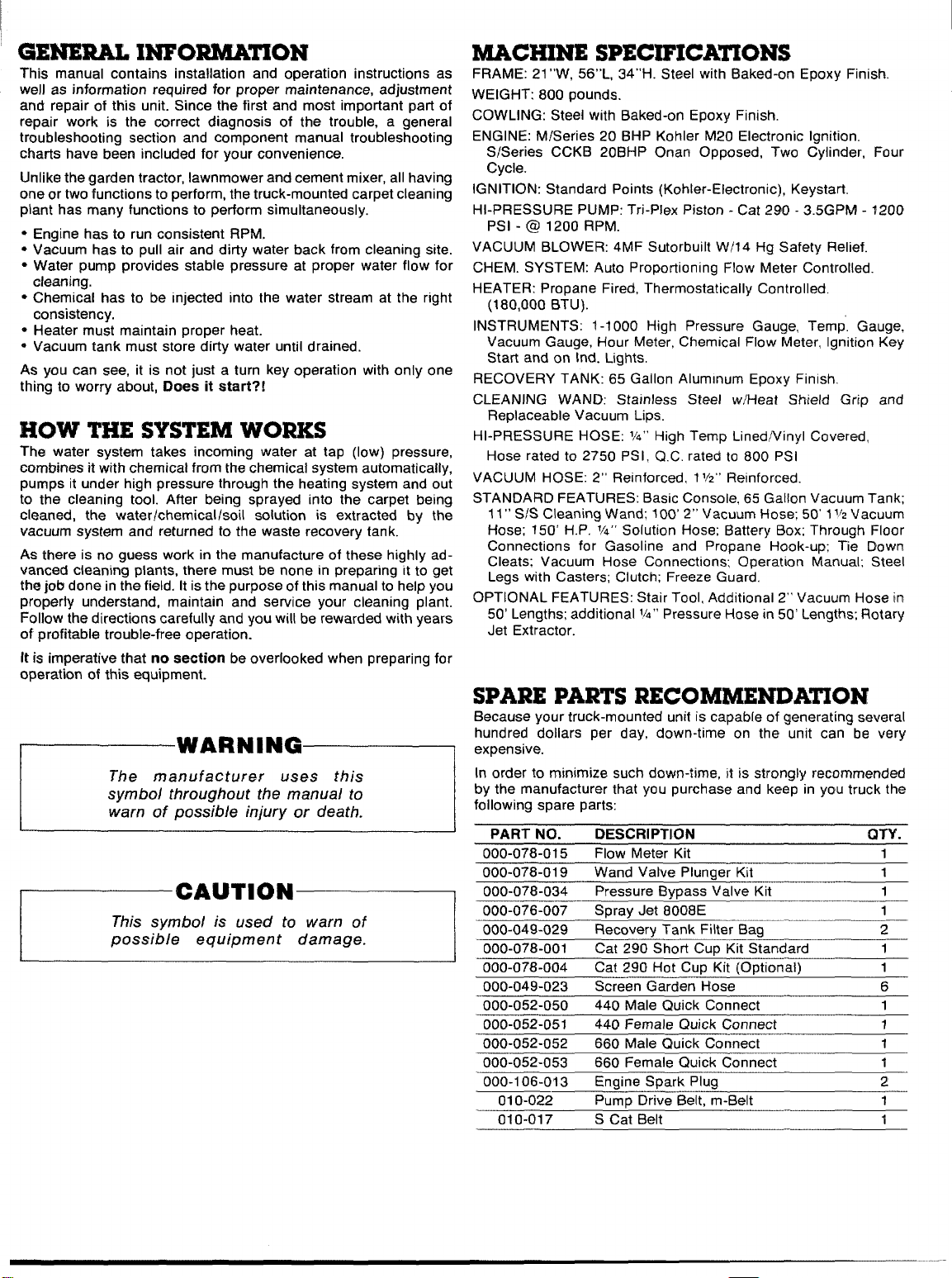
MACHINE SPECIFICA~ONS
FRAME: 21 “W, 56”L, 34”H. Steel with Baked-on Epoxy Finish.
WEIGHT: 800 pounds.
COWLING: Steel with Baked-on Epoxy Finish.
ENGINE: M/Series 20 BHP Kohler M20 Electronic Ignition.
S/Series CCKB 20BHP Onan Opposed, Two Cylinder, Four
Cycle.
IGNITION: Standard Points (Kohler-Electronic), Keystart,
HI-PRESSURE PUMP: Tri-Plex Piston - Cat 290- 3.5GPM -1200
PSI - @ 1200 RPM.
VACUUM BLOWER: 4MF Sutorbuilt W/14 Hg Safety Relief.
CHEM. SYSTEM: Auto Proportioning Flow Meter Controlled.
HEATER: Propane Fired, Thermostatically Controlled.
(180,000 BTU).
INSTRUMENTS: 1-1000 High Pressure Gauge, Temp. Gauge,
Vacuum Gauge, Hour Meter, Chemical Flow Meter, Ignition Key
Start and on lnd. Lights.
RECOVERY TANK: 65 Gallon Aluminum Epoxy Finish,
CLEANING WAND: Stainless Steel w/Heat SMeld Grip and
Replaceable Vacuum Lips.
HI-PRESSURE HOSE: M“ High Temp LinedNinyl Covered,
Hose rated to 2750 PSI, Q.C. rated to 800 PSI
VACUUM HOSE: 2“ Reinforced, 11/2”Reinforced.
STANDARD FEATURES: Basic Console, 65 Gallon Vacuum Tank;
11” S1S Cleaning Wand; 100’ 2“ Vacuum Hose; 50’ 11~2Vacuum
Hose; 150’ H.P. M“ Solution Hose; Battery Box; Through Floor
Connections for Gasoline and Propane Hook-up; Tie Down
Cleats; Vacuum Hose Connections; Operation Manual; Steel
Legs with Casters; Clutch; Freeze Guard,
OPTIONAL FEATURES: Stair Tool, Additional 2“ Vacuum Hose in
50’ Lengths; additional
1/4” Pressure Hose in 50’ Lengths; Rotary
Jet Extractor.
SPARE PARTS RECOMMENDATION
Because your truck-mounted unit is capabte of generating several
hundred dollars per day, down-time on the unit can be very
expensive.
In order to minimize such down-time, it is strongly recommended
by the manufacturer that you purchase and keep in you truck the
following spare parts:
PART NO. DESCRIPTION
000-078-015
000-078-019
000-078-034
000-076-007
000-049-029 ‘
000-078-001
000-078-004
000-049-023
000-052-050 . .. .... .
000-052-051
000-052-052
000-052-053
000-11 -)6- 04?I
------ ---
010-022
010-017
Flow Meter Kit
Wand Valve Plunger Kit
Pressure Bypass ~alve Kit
Soray Jet 8008E
Recovery Tank Filter Ba~
Cat 290 ‘Short CUP Kit S~andard
Cat 290 Hot Cup Kit ~mntifin=~~
Scr,
_-.”een Garden Hose
44o Male Quick Connect
44o Fer
660 Mal~
66o Ferr---- _-,.
Fnnin~ Snark PII
_,, =...-
nale Quick Connect
Ie Quick Connect
nab C)L;ickconnect
-r -.. .
Pump Drive Belt, m-!3elt
S Cat Belt
,-,- ..-..-.,
.Ug 2
QTY.
1
1
1
1
2
_——
1
1
6
1
7
1
1
1
1
Page 4
HOW TO ORDER
—
To obtain a proper diagnosis of your malfunction, and to order
warranty replacement parts, it is important that you proceed in the
following manner
1. Call HydraMaster Warranty/Service Dept. at (206) 775-7275.
2. Give the Warranty/Service Representative the following
information:
A. Name of your company and your address.
B. Equipment Model (i.e. Hydra-Cat, Bobcat 2, etc.).
C. Date of purchase.
D. Hours on the unit.
E. Serial number of unit.
F. Name of person authorized to order parts.
G. Salesman unit purchased from.
H. Description of malfunction.
1. Pressure readings on high pressure gauge with wand turned
on and off.
3. If warranty replacement parts are needed, please specify
method of shipment desired. NOTE: All replacement parts are
sent freight collect, via:
A. U.P.S.
B, Air Freight
C. Air Mail
D. Air Express
E. Auto Freight
Do not give malfunctioning parts to a HydraMaster Sales or
4,
Service Representative. All parts must be returned directly
to HydraMaster, freight prepaid.
PARTSORDERS
To expedite your parts needs, please call your sales representative. In most instances, he either stocks or has access to parts
through a regional service center.
In the event parts are unavailable locally, contact the factory and
coordinate your needs. If this becomes necessary, always indicate
the method of shipment you desire, i.e. U.P.S. Blue Label, Air
Freight, Air Express, etc.
HydraMaster Parts Dept. phone (206) 775-7276.
ONE FINAL NOTE
Any questions you have regarding the warranty program should be
directed to the Warranty/Service Dept. Personnel at HydraMaster
Corporation.
We shall always endeavor to be fair in our evaluation of your
warranty claim, and shall provide you with a complete analysis of
our findings.
PURCHASER’SRESPONSIBILITY
PRIOR TO ARRIVAL OF UNIT:
● Install 5/8” exterior plywood flooring in vehicle and cover with
artificial turf.
● Have belly mounted propane tank installed on vehicle. Tank
must be propane vapor type.
● Caution Purchase heavy duty 42-60 amp hour battery and have
battery ‘slow’ charged if new. If battery is not fully charged
damage can occur to the engine charging regulator.
READING OF OWNERS MANUAL:
Itis the purchaser’s responsibility to read the unit operation
o
manual and to familiarize himself with the information contained
therein.
SALESREPRESENTATIVE’S
RESPONSIBILITY
ACCEPTANCE OF SHIPMENT:
If unit shows any outward signs of damage, do not sign the
*
delivery receipt until you have closely inspected the unit and
noted any damage on the delivery receipt. Have the freight company representative acknowledge the damage by signing the
notation of damage on the delivery receipt.
● The salesman from whom you purchased your unit is responsi-
ble for supervising the correct installation of the unit in your vehicle and thoroughly training you in its operation and
maintenance.
CORRECT INSTALLATION INCLUDES:
Supervising the purchaser in the following:
● Installation of through-floor fittings for propane and gasoline fuel
lines; installing propane regulator included with unit, outside
vehicle placing unit and recovery tank in vehicle and securing
them with bolts or tie down cleats; connecting all propane and
gasoline lines; connecting battery; checking pump, vacuum
blower and engine oil levels, prior to starting unit; starting unit to
check engine to see that all systems function normally also
checking all hoses, wands, etc., for correct operation.
TRAINING SHALL INCLUDE:
● Thorough review of the operation manual with purchaser; in-
struction and familiarization in: how to correctly start up and shut
down unit; how to correctly clean with the unit; how, where and
how often to check and change component oil levels; how the
unit’s systems work; how to troubleshoot the unit; how to do
basic repairs; safety precautions and their importance; freezing
damage and how to avoid it and a thorough review of the unit
warranty and warranty procedures.
HydraMaster warranty policy (Inside back cover)
Effective May 1, 1988
HydraMaster warranty covers only defective materials and/or
workmanship for the periods listed. Labor, and/or diagnostic
reimbursement is specifically excluded.
HOURS:
MONDAY THROUGH FRIDAY
am TO 6:00 pm
8:00
PACIFIC STANDARD TIME
@ @ @ @ ,AX ANDhIlARKETIt4G~~~~~
PST
..!:\;.::::*”..
ROCK MT.
CENTRAL
~:;;>;.$%,
EASTERN
TELEPHONE NUMBERS
GENERAL OFFICES:
PARTS DEPT
SERVICE/WARRANTY:
NEW EQUIPMENT SALES
(206) 775-7272
(206) 775-7276
Page 5
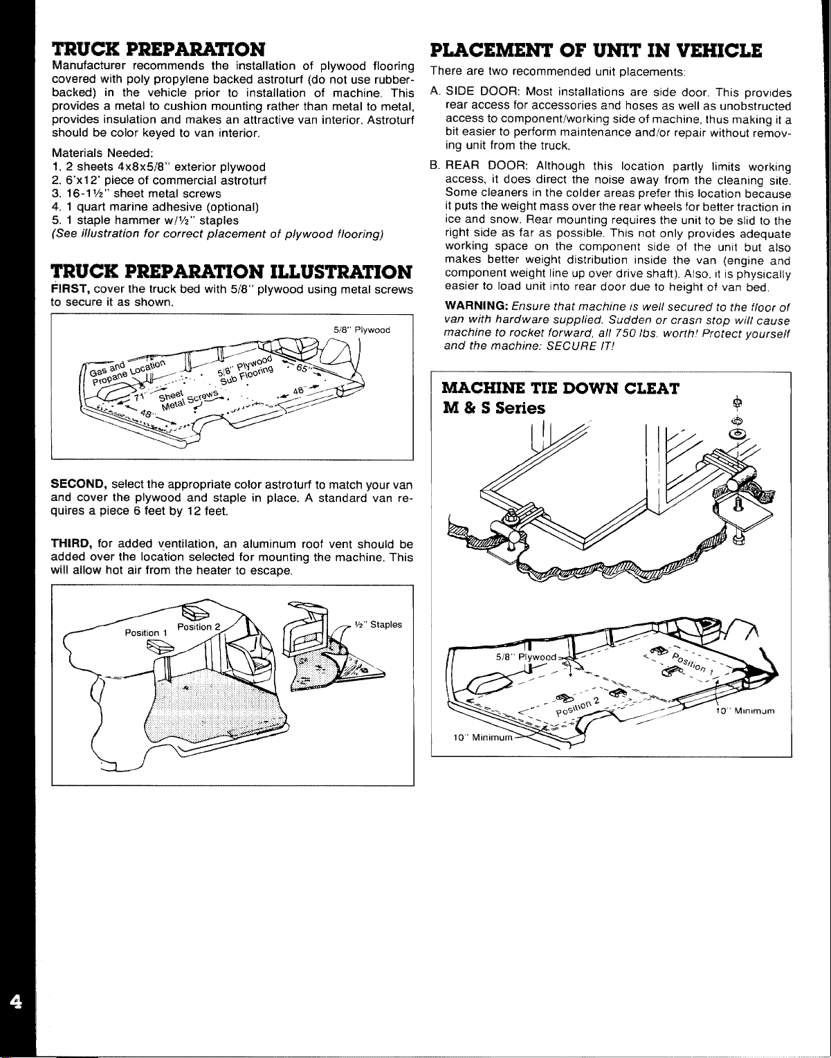
TRUCK PREPARATION
Manufacturer recommends the installation of plywood flooring
covered with poly propylene backed astroturf (do not use rubberbacked) in the vehicle prior to installation of machine, This
provides a metal to cushion mounting rather than metal to metal,
provides insulation and makes an attractive van interior. Astroturf
should be color keyed to van interior,
Materials Needed:
1.2 shaets 4x8x5f8° exterior plywood
2. 67X12’ piece of commercial astroturf
3. 16.1 VZ”sheet metal screws
4.1 quart marine adhesive (optional)
5.1 staple hammer w/VZ” staples
(See illustration for correct placement of plywood flooring)
TRUCK PREPARATION ILLUSTRATION
FIRST, cover the truck bed with 5/8” ~lvwood usmq metal screws
to secure it as shown.
.
PLACEMENT OF UNIT IN VEHICLE
There are two recommended unit placements:
A. SIDE DOOR: Most installations are side door. This provides
rear access for accessories and hoses as well as unobstructed
access to component/working side of machine, thus making it a
bit easier to perform maintenance andlor repair without removing unit from the truck.
B. REAR DOOR: Although this location partly limits workina
access, it does direct the noise away from the cleaning sit;
Some cleaners in the colder areas prefer this location because
it puts the weight mass over the rear wheels for better traction in
ice and snow, Rear mounting requires the unit to be slid to the
right side as far as possible. This not only provides adequate
working space on the component side of the unit but also
makes better weight distribution inside the van (engine and
component weight line up over drive shaft). Also, It is physically
easier to load unit into rear door due to height of van bed,
WARNING: Ensure that machine IS we// secured to the floor of
van with hardware supplied. Sudden or cra.sn stop will cause
machine to rocket forward, all 750 Ibs. worth I Protect yourself
and the machine: SECURE IT!
MACHINE TIE DOWN CLEAT
M & S Series
$
SECOND, select the appropriate color astroturf to match your van
and cover the plywood and staple in place. A standard van requires a piece 6 feet by 12 feet.
THIRD, for added ventilation, an aluminum roof vent should be
added over the location selected for mounting the machine. This
‘ill allow hot air from the heater to escape, -
&L--J
Page 6
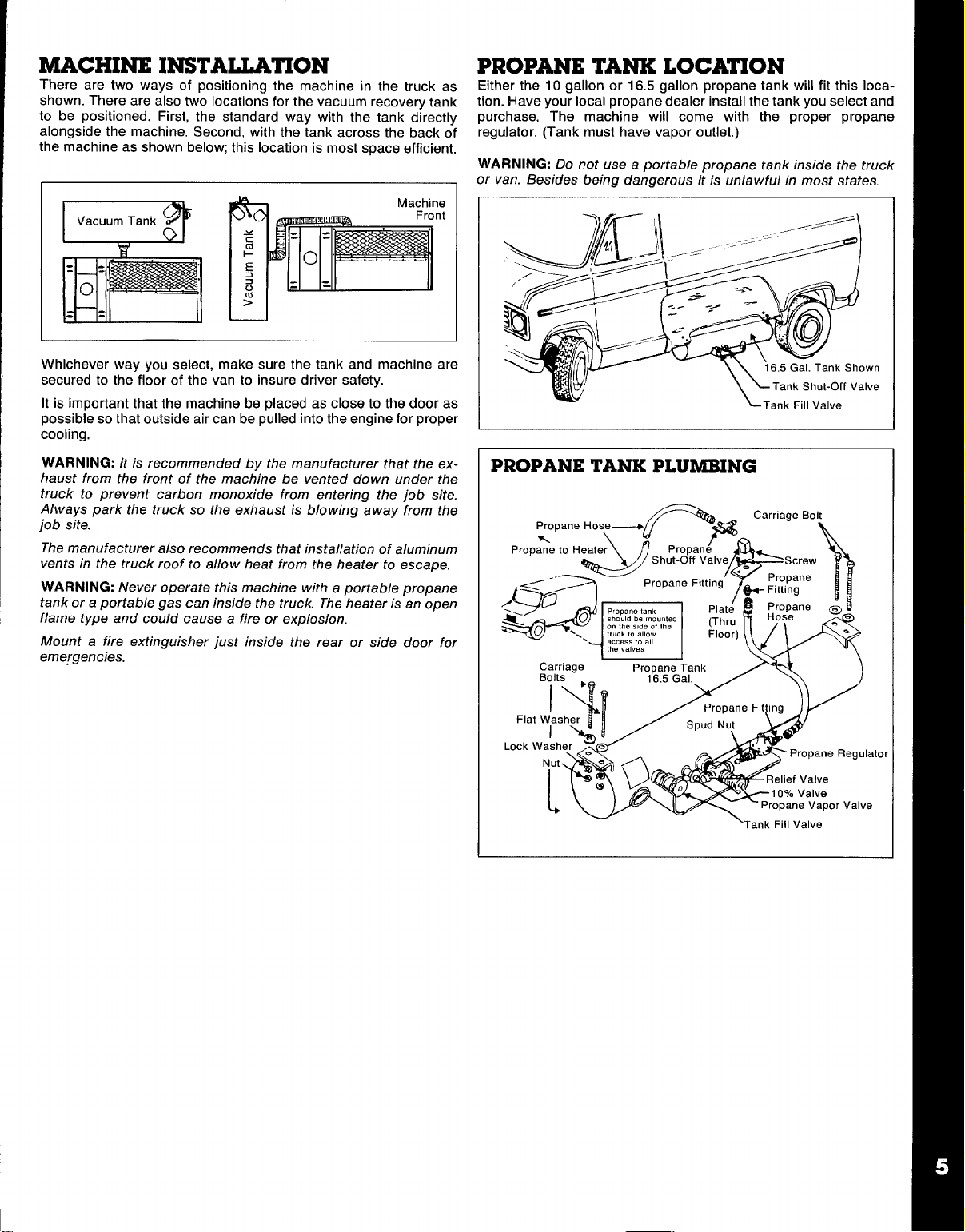
MACHINE INSTALLATION
There are two ways of positioning the machine in the truck as
shown. There are also two locations for the vacuum recovery tank
to be positioned. First, the standard way with the tank directly
alongside the machine, Second, with the tank across the back of
the machine as shown below; this location is most space efficient.
PROPANE TANK LOCATION
Either the 10 gallon or 16.5 gallon propane tank will fit this location. Have your local propane dealer install the tank you select and
purchase. The machine will come with the proper propane
regujator. (Tank must have vapor outlet.)
WARNING: Do not use a portable DroDane tank inside the truck
or van. Besides being dangerous ii is “unla wful in most states.
Whichever way you select, make sure the tank and machine are
secured to the floor of the van to insure driver safety.
I
It is important that the machine be placed as close to the door as
possible so that outside air can be pulled into the engine for proper
cooling.
WARNING:
haust from the front of the machine be vented down under the
truck to prevent carbon monoxide from entering the job site.
Always park the truck so the exhaust is blowing away from the
job site.
The manufacturer also recommends that installation of aluminum
vents in the truck roof to allow heat from the heater to escape.
WARNING: Never operate this machine with a portable propane
I
tank or a portable gas can inside the truck. The heater is an open
flame type and could cause a fire or explosion.
Mount a fire extinguisher just inside the rear or side door for
emergencies.
Itis recommended by the manufacturer that the ex-
wn
Ive
PROPANE TANK PLUMBING
Iator
e
Page 7
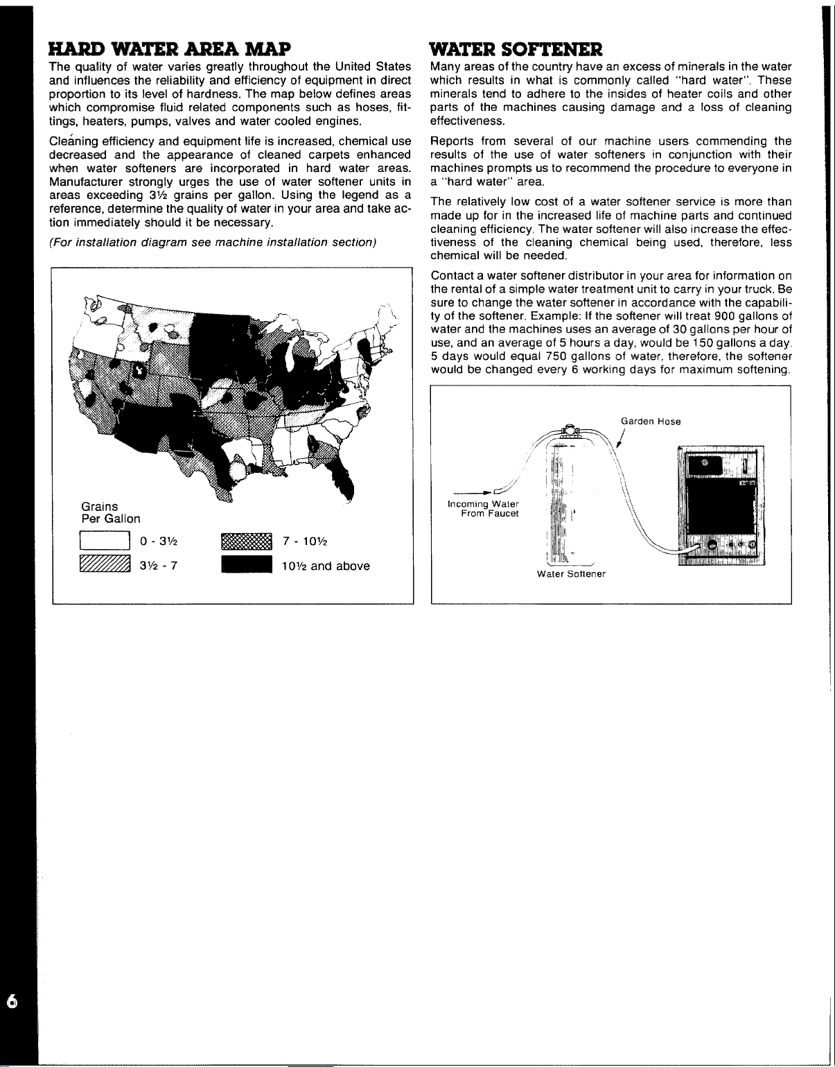
HARI) WA~R AREA MAP
The quality of water varies greatly throughout the United States
and influences the reliability and efficiency of equipment in direct
proportion to its level of hardness. The map below defines areas
which compromise fluid related components such as hoses, fittings, heaters, pumps, valves and water cooled engines.
Cleaning efficiency and equipment life is increased, chemical use
decreased and the appearance of cleaned carpets enhanced
when water softeners are incorporated in hard water areas.
Manufacturer strongly urges the use of water softener units in
areas exceeding 31A grains per gallon. Using the legend as a
reference. determine the cmalitv of water in vow area and take action imm~diately should ii be ~ecessary. ‘
(For installation diagram see machine installation section)
WATERSOFTENER
Many areas of the country have an excess of minerals in the water
which results in what is commonly called “hard water”, These
minerals tend to adhere to the insides of heater coils and other
parts of the machines causing damage and a loss of cleaning
effectiveness.
Reports from several of our machine users commending the
results of the use of water softeners in conjunction with their
machines prompts us to recommend the procedure to everyone in
a “hard water” area.
The relatively low cost of a water softener service is more than
made up for in the increased life of machine parts and continuad
cleaning efficiency, The water softener will also increase the effectiveness of the cleaning chemical being used, therefore, less
chemical will be needed.
Contact a water softener distributor in your area for information on
the rental of a simple water treatment unit to carry in your truck. Be
sure to change the water softener in accordance with the capability of the softener, Example: If the softener will treat 900 gallons of
water and the machines uses an average of 30 gallons per hour of
use, and an average of 5 hours a day, would be 150 gallons a day,
5 days would equal 750 gallons of water, therefore. the softener
would be changed every 6 working days for maximum softening.
Grains
Per Gallon
u 0-31’2
- 3% -7
..
= 7- 107/2
_ 101/2 and above
— d“
Incoming Water
From Faucet
Water Sottener
Page 8
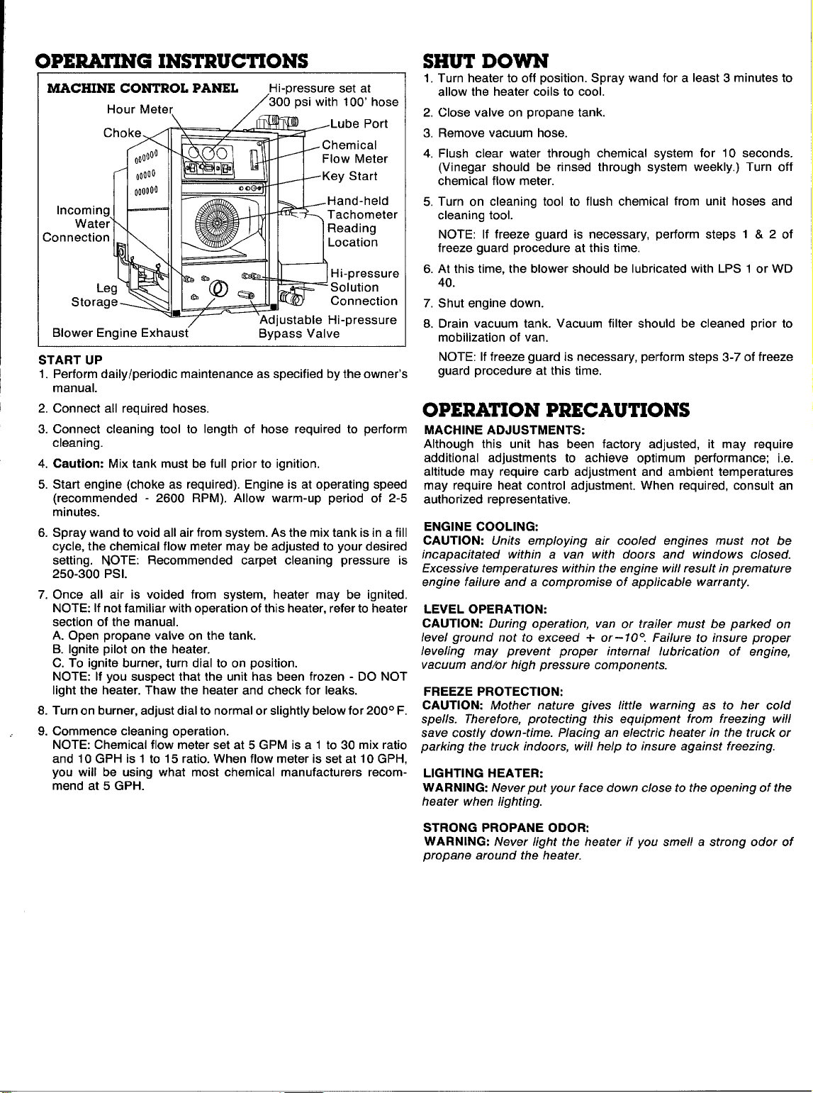
hPERATINGINSTRUCTIONS
MACHINE CONTROL PANEL
Hour Meter
In
;on
Blower Engine Exhaust’
START UP
1. Perform daily aperiodic maintenance as specified by the owner’s
manual.
2. Connect all required hoses.
3. Connect cleaning tool to length of hose required to perform
cleaning.
4. Caution: Mix tank must be full prior to ignition.
5. Start engine (choke as required). Engine is at operating speed
(recommended -2600 RPM). Allow warm-up period of 2-5
minutes.
6. Spray wand to void all air from system. As the mix tank is in a fill
cycle, the chemical flow meter may be adjusted to your desired
setting. NOTE: Recommended carpet cleaning pressure is
250-300 PSI.
7. Once all air is voided from system, heater may be ignited.
NOTE: If not familiar with operation of this heater, refer to heater
section of the manual.
A. Open propane valve on the tank.
B. Ignite pilot on the heater.
C. To ignite burner, turn dial to on position.
NOTE: If you suspect that the unit has been frozen - DO NOT
light the heater. Thaw the heater and check for leaks.
8. Turn on burner, adjust dial to normal or slightly below for 200° F.
9. Commence cleaning operation.
NOTE: Chemical flow meter set at 5 GPM is a 1 to 30 mix ratio
and 10 GPH is 1 to 15 ratio. When flow meter is set at 10 GPH,
you will be using what most chemical manufacturers recom-
mend at 5 GPH.
Hi-pressure set at
300 psi with 100’ hose
/
Bypass Valve
1. Turn heater to off position. Spray wand for a least 3 minutes to
allow the heater coils to cool.
2. Close valve on propane tank.
3. Remove vacuum hose.
4. Flush clear water through chemical system for 10 seconds.
(Vinegar should be rinsed through system weekly.) Turn off
chemical flow meter.
5. Turn on cleaning tool to flush chemical from unit hoses and
cleaning tool.
NOTE: If freeze guard is necessary, perform steps 1 & 2 of
freeze guard procedure at this time.
6. At this time, the blower should be lubricated with LPS 1 or WD
40.
7. Shut engine down.
8. Drain vacuum tank. Vacuum filter should be cleaned prior to
mobilization of van.
NOTE: If freeze guard is necessary, perform steps 3-7 of freeze
guard procedure at this time.
OPERATION PRECAUTIONS
MACHINE ADJUSTMENTS:
Although this unit has been factory adjusted, it may require
additional adjustments to achieve optimum performance; i.e.
altitude may require carb adjustment and ambient temperatures
may require heat control adjustment. When required, consult an
authorized representative.
ENGINE COOLING:
CAUTION: Units employing air cooled engines must not be
incapacitated within a van with doors and windows closed.
Excessive temperatures within the engine will result in premature
engine failure and a compromise of applicable warranty.
LEVEL OPERATION:
CAUTION: During operation, van or trailer must be parked on
level ground not to exceed i- or- 10°. Failure to insure proper
leveling may prevent proper internal lubrication of engine,
vacuum andlor high pressure components.
FREEZE PROTECTION:
CAUTION: Mother nature gives /itt/e warning as to her cold
spells. Therefore, protecting this equipment from freezing will
save costly down-time. Placing an electric heater in the truck or
parking the truck indoors, will help to insure against freezing.
LIGHTING HEATER:
WARNING: Never put your face down close to the opening of the
heater when lighting.
STRONG PROPANE ODOR:
WARNING: Never light the heater if you smell a strong odor of
propane around the heater.
Page 9
FREEZEPROTECTION
Any freezing of this machine is not covered by warranty and during the colder months of operation, careful protection should be of
utmost concern.
THE FOLLCWING PRECAUTIONS ARE RECOMMENDED:
1. Run machine before leaving for the first job to insure nothing
has frozen the night before, including hoses and wand.
2. Insulate the garden hose from the cold ground by running it
through an extra 1
3. Leave truck doors closed until time cleaning begins, then open
slightly.
4. on extremely cold days propane does not vaporize as quickly,
therefore, venting the warm exhaust over to blow on the propane tank will stabilize the propane flow. (This is necessary if
you notice a drop in heat or a low burning flame in the heater.)
5. In colder climates, insulating the truck walls and floor boards will
help protect the unit.
6. Don’t procrastinate during the cleaning operation or the hot
water solution line will also freeze on the ground. The solution
line should be insulated in extremely cold climates.
T. Whenever possible, the truck and machine should be stored in a
heated garage at night or over the weekend. If not possible,
place a 1500 watt electric heater inside the truck, aimed directly
at the machine. Never use a propane heater - it causes excessive moisture on the truck ceiling and the possibility of it
going out is higher. If the machine and truck are left outside with
a heater, you should first drain all possible water from the
machine cleaning tools and hoses. (They freeze also.)
TO DRAIN THE MACHINE, FOLLOW THESE STEPS:
A. Before shutting off the machine, remove the chemical line from
the chemical jug and place in a mixture of 50/50 anti-freeze and
water. With the cleaning tool on, allow mixture to fill chemical
system back to the chemical mix tank.
B. Loosen the petcock valve on your bypass drain hose and allow
the water to drain thoroughly from the mix tank.
C. To remove the water from the heater and pump use the freeze
guard which is a small air compressor. Using the correct connectors, first blow air into the high pressure solution male quick
connect. This will force the water through the heater back
through the pump and into the chemical mix tank to be drained
out through the petcock valve to the ground. By loosening the
bypass knob, the air will be allowed to flow more freely through
the system. Next, blow the air into the incoming water quick
connect and force that water into the chemical mix tank to be
drained out.
D. Remember to close the drain valve prior to next operation of
your unit.
BE SURE ITS PROTECTED!
Freezing will cause GRIEF, MONEY and DOWN-TIME. Don’t
mess with Mother Nature!
V2 inch vacuum hose.
CAUTION: When c/caning cut-pile acri/an p/u.sh carpefs, using
high heat setting may result in fiber damage on this type of
carpet.
The use of some chemicals through your mobile carpet cleaning
plant can seriously damage the internal plumbing, high pressure
pump and heater. (Chemical such as concentrated acids and
some paint oil and grease removers w/high concentration of
solvents.)
Manufacturer recommends only the use of chemicals containing
rust and corrosion inhibitors and water softening agents to prevent
chemical build-up.
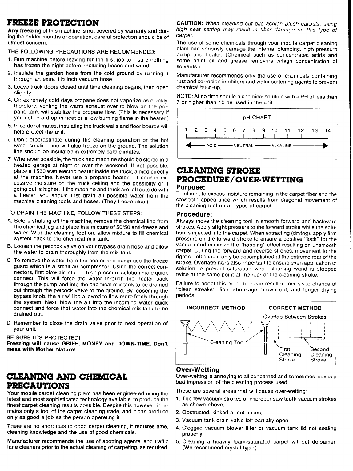
NOTE: At no time should a chemical solution with a Pti of less than
7 or higher than 10 be used in the unit,
pli CHART
1
234567891011121314
I
+ACID
I I I I
— NEUTRAL
—“’’A””’ ~
I I
I
CLEANING STROKE
PROCEDURE/ OVER-WVETTING
Purpose:
To eliminate excess moisture remaining in the carpet fiber and the
sawtooth appearance which results from diagonal movement of
the cleaning tool on all types of carpet,
Procedure:
Always move the cleaning tool in smooth forward and backward
strokes. Apply slight pressure to the forward stroke while the solu-
tion is injected into the carpet. When extracting (drying), apply firm
pressure on the forward stroke to ensure a positive “lock” for the
vacuum and minimize the “hopping” effect resulting on unsmooth
carpet. During the forward and reverse strokes, movement to the
right or left should only be accomplished at the extreme rear of the
stroke, Overlapping is also important to ensure even application of
solution to prevent saturation when cleaning wand is stopped
twice at the same point at the rear of the cleaning stroke,
Failure to adopt this procedure can result in increased chance of
“clean streaks”, fiber shrinkage, brown out, and longer drying
periods.
INCORRECT METHOD CORRECT METHOfJ
\/
\cleaning Tool ‘
v“
Overlao Between Strokes
!
%
/-4
II
@ LJ ~:
u
11,1
First
““
Cleanina
Stroke -
Second
Cleaning
Stroke
‘1
CLEANING AND CHEMICAL
PRECAUTIONS
Your mobile carpet cleaning plant has been engineered using the
latest and most sophisticated technology available, to produce the
finest carpet cleaning results possible. Despite this however, it remains only a tool of the carpet cleaning trade, and it can produce
cmly as good a job as the person operating it.
There are no short cuts to good carpet cleaning, it requires time,
cleaning knowledge and the use of good chemicals.
Manufacturer recommends the use of spotting agents, and traffic
lane cleaners prior to the actual cleaning of carpeting, as required.
Over-Wetting
Over-wetting is annoying to all concerned and sometimes leaves a
bad impression of the cleaning process used.
These are several areas that will cause over-wetting:
1.
Too few vacuum strokes or improper saw tooth vacuum strokes
as shown above.
2,
Obstructed, kinked or cut hoses,
Vacuum tank drain valve left partially open.
3.
4,
Clogged vacuum blower filter or vacuum tank lid not sealing
properly.
Cleaning a heavily foam-saturated carpet without defoamer.
5.
(We recommend crystal type,)
Page 10
This system has been designed to be the most simple and troublefree ever.
The incoming water flows directly to the mix tank. Water will now
flow through a proportioning valve which will simultaneously mix
the chemical to achieve your desired solution, The mix tank is
equipped with 2 different float valves, one of which responds to the
water level of the tank and will maintain the proper volume of solution to be reserved for the cat pump. The secondary float vahe is a
safety valve that is designed to protect your system from sudden or
unexpected loss of water supply. If, for example, the water source
at the house was turned off, the water level of the mix tank would
drop, activating the secondary valve which automatically kills the
engine,
UNIT WITH CLUTCH: If mix tank water level drops, clutch will
disengage.
In conjunction with the incoming flow, the chemical ratio may be
obtained by an adjustment of the chemical flow meter during the fill
cycle of the mix tank. The chemical will flow from the chemical jug
to the chemical flow meter, then to the proportioner where it is
distributed into the mix tank at your desired proportion. This line
should be flushed with vinegar weekly to prevent abnormal
chemical build-up. This may be done by removing the clear plastic
hose from the chemical jug and inserting it into a one quart container of vinegar. This should be done with the chemical flow meter
setting on 10 GPH with heater “off”. Simply spray the wand for the
duration of the vinegar in the one quart container, then repeat the
process with one quart of clear water to void all lines of vinegar.
NOTE: With this unique chemical system, your chemical flow is
proportioned to the filling cycles of the mix tank, not the direct
spraying of the wand. Therefore, it is possible that as your wand is
spraying, you may have no chemical flow, Also, the converse is
true in that you may not be spraying your wand but, if the mix tank
is in a filling cycle your chemical flow meter may read your desired
flow.
This chemical system will mix a 1 to 30 ratio when flow meter is set
at 5 GPH. Most chemical suppliers will recommend a 1 to 15 ratio
therefore you can either set the flow meter at 10 GPH, giving you a
1 to 15 ratio of chemical to cleaning water, or double the recommended strength of chemical in the 5 gallon jug and set the flow
meter at 5 GPH, thereby attaining a 1 to 15 ratio. (It is recommended that you set the flow meter at 10 GPH for overall best
results.)
The water will now be siphoned from the bottom of the mix tank to
the Cat Pump. If the wand is not spraying, the water will bypass
from the bottom of the brass pressure relief valve to the mix tank.
If the wand is spraying, the water will then flow to the heater. This
heater has a capacity of up to 2 gallons, therefore it is extremely
important that all air is bled out of the heater prior to initial start-up.
This may be achieved by running the system, without the heater
on, for approximately 60 seconds.
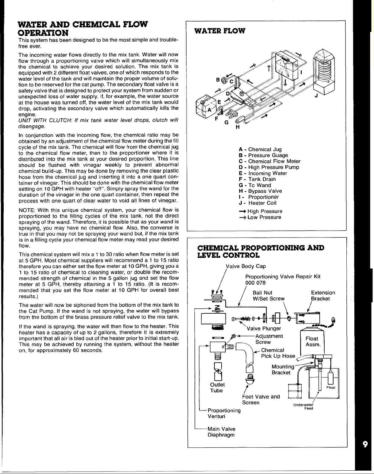
WATER FLOW
H
A - Chemical Jug
B - Pressure Guage
C - Chemical Flow Meter
D - High Pressure Pump
E - Incoming Water
F - Tank Drain
G - To Wand
H - Bypass Valve
I - Proportioner
J - Heater Coil
-+ High Pressure
+ Low Pressure
CHEMICAL PROPORTIONING AND
LEVEL CONTROL
Diaphragm
Page 11
CHEMICAL TANK TROUBLESHOOTING GUIDE
PROBLEM: No or Low Chemical Flow
Solution
Check that hoses in the tank are secured. Check that the
hose from the top of the flow meter to the side of the mix
tank is secured with no kinks. Check the hose from the
bottom of the flow meter to the chemical jug for kinks or
cracks.
Check the foot valve and screen on the end of the hose
which goes into the mix tank. To check this screen for
proper function, remove it from the plastic hose. You
should be able to suck through the hose barb end, but you
should not be able to blow through the hose barb end. (If
you can not suck through it then rinse it out with vinegar, )
When screen is removed the chemical fill hose should be
lifted into a vertical position
will seat by gravity. (This is only a temporary fix for low
water pressure areas. )
Check flow meter for float obstruction.
Check to insure that the adjusting screw on proportioning
venturi is backed out.
Is proportioning venturi closed? Soak in warm water or
vinegar solution.
Is incoming water pressure less than 20 PSI?
Cracked or defective chemical flow meter?
NCITE: If you are in a low water pressure area and find that
volume of water entering the mix tank is not enough to
the
allow your venturi to siphon chemical, unscrew the spring
from the foot valve screen and remove the spring.
so the ball in the foot valve
PROBLEM: Mix Tank Doesn’t Keen UCIWith Water Outnut
Solution
Check garden hose quick connect assembly screen.
Check garden hose andlor feed hose to the mix tank for clog,
kinks or blockage.
Float ball in mix tank hanging up. (Not moving freely.)
Extension bracket pinching float lever, restricting full action of
lever.
Valve plunger not opening fully. To adjust, remove the 2
screws which hold the extension assembly to the valve.
(Do not lose or drop the screws. ) Remove the extension
assembly, turn it up side down. To adjust, loosen the set
screw on the ball nut. Place your thumb on the plunger
and press it In 1/16” and slide the ball nut w/set screw
toward the plunger end 1/1 6“’. Tighten the set screw.
Place the extension assembly back into position. If the
tank starts to overfill, the ball nut is to close to the valve
plunger and should be moved back away from the valve
olunaer sliahtlv.
PROBLEM: Pump Pulsates When The Tank Is in a Fill Mode
Solution
Check that the hose which goes from the gray plastic venturi
to the bottom of the tank is not directed toward the Cat
pump pick up port. If it is, aim it in another direction.
1
PROBLEM: Inability to Adjust Chemical with the Flow Meter
Solution
Debris lodged behind teflon seat in flow meter knob,
Teflon seat dismounting from flow meter knob.
PROBLEM: Solution Reversing from Mix Tank to Chemical
solution
Anti-siphon screen removed from chemical jug hose.
Debris in anti-siphon screen.
PRt3HLElW Mix Tank Overflows
solution
Float ball in mix tank hanging up (not moving freely).
Extension bracket pinching the float lever, restricting full
action of the lever.
Plunger not seating properly on the valve. (Remove the 2
screws which hold the extension assembly to the valve.
Do not lose or drop the screws. Remove the extension
assembly. Turn it upside down. Inspect the plunger for
proper seating. If there is no debris obstructing the valve
or plunger, the plunger may be out of adjustment. To ad-
just, loosen the se! screw on the ball nut and move the
ball toward the end of the rod 1/16”. Retighten set screw,
Place extension assembly back into position. Tighten the
two screws.
Jug
Page 12
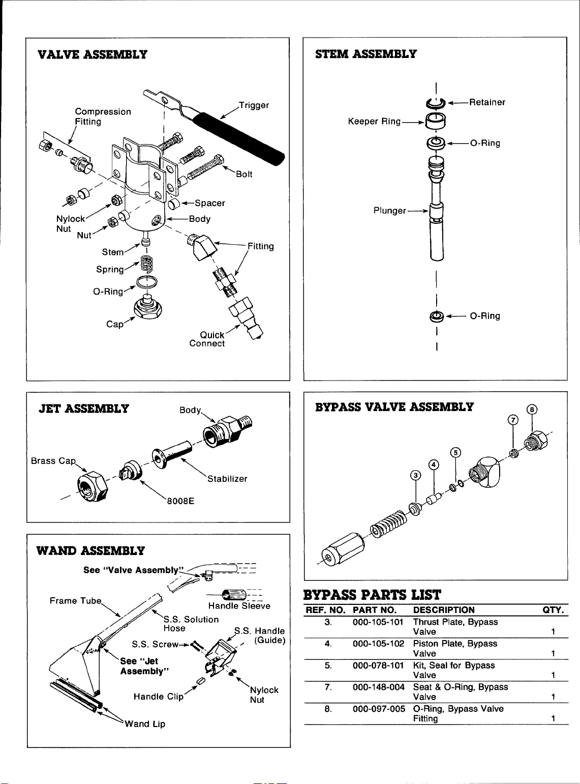
VALVE ASSEMBLY
STEM ASSEMBLY
Keeper Ring—
I
+--Retainer
w
~
_C)-Ring
I
I
@—
I
1
O-Ring
JET ASSEMBLY
Brass Cap
,a”0a<800~St~bilizer
WAND ASSEMBLY
See “Valve Assembly”
/
Body
‘--% “
@
P
BYPASS VALVE ASSEMBLY
?@8
.. ————
BYPASS PARTS LIST
S.S. Handle
REF. NO. PART NO. DESCRIPTION
3. 000-105-101 Thrust Plate, Bypass
4.
000-105-102 Piston Plate, Bypass
5.
000-078-101 Kit, Seal for Bypass
7.
000-148-004 Seat & O-Ring, Bypass
8. 000-097-005 O-Ring, Bypass Valve
Valve -‘
Valve
Valve
Valve
Fittina
QTV.
1
1
1
1
1
Page 13
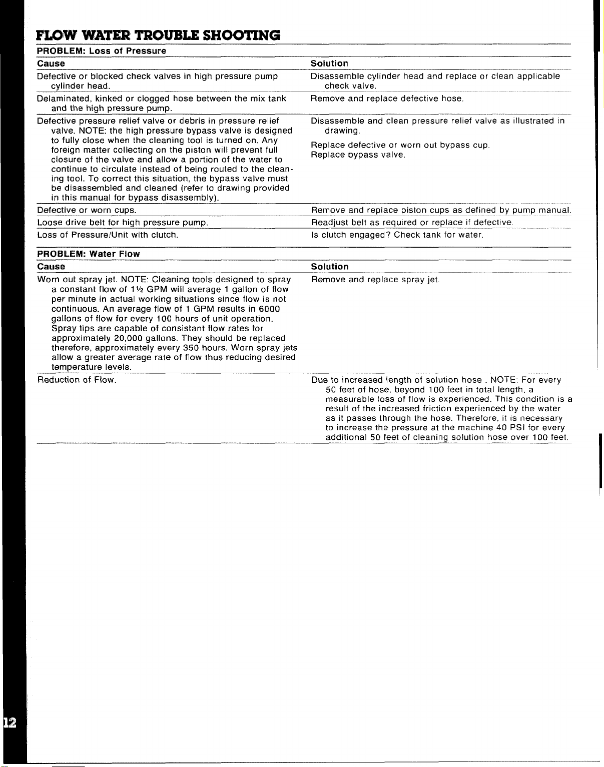
FLOW WATER TROUBLESHOOTING
PROBLEM: Loss of Pressure
Cause
Defective or blocked check valves in hicfh pressure pump
cylinder head.
Delaminated, kinked or clogged hose between the mix tank
and the high pressure pump.
Defective pressure relief valve or debris in pressure relief
valve. NOTE: the high pressure bypass valve is designed drawing.
to fully close when the cleaning tool is turned on. Any
foreign matter collecting on the piston will prevent full
closure of the valve and allow a oortion of the water to
continue to circulate instead of being routed to the cleaning tool. To correct this situation, the bypass valve must
be disassembled and cleaned (refer to drawing provided
in this manual for bypass disassembly).
Defective or worn cups.
Loose drive belt for high pressure pump. Readjust belt as required or replace if defect!ve.
Loss of Pressure/Unit with clutch.
PROBLEM: Water Flow
Cause Solution
Worn out spray jet. NOTE: Cleaning tools designed to spray
a constant flow of 1V2GPM will average 1 gallon of flow
per minute in actual working situations since flow is not
continuous. An average flow of 1 GPM results in 6000
gallons of flow for every 100 hours of unit operation.
Spray tips are capable of consistent flow rates for
approximately 20,000 gallons. They should be replaced
therefore, approximately every 350 hours. Worn spray jets
allow a greater average rate of flow thus reducing desired
temperature levels.
Reduction of Flow.
Solution
Disassemble cylinder head and replace or clean applicable
check valve,
Remove and replace defective hose,
—
Disassemble and clean pressure relief valve as illustrated in
Replace defective or worn out bypass cup.
Replace bypass valve.
Remove and replace piston cups as defined by pump manual.
Is clutch engaged? Check tank for water,
Remove and replace spray jet.
Due to increased iength of solution hose NOTE: For every
50 feet of hose, beyond 100 feet in total length, a
measurable loss of flow is experienced. This condition is a
result of the increased friction experienced by the water
as it passes through the hose. Therefore, it is necessary
to increase the pressure at the machine 40 PSI for every
additional 50 feet of cleaning solution hose over 100 feet,
Page 14
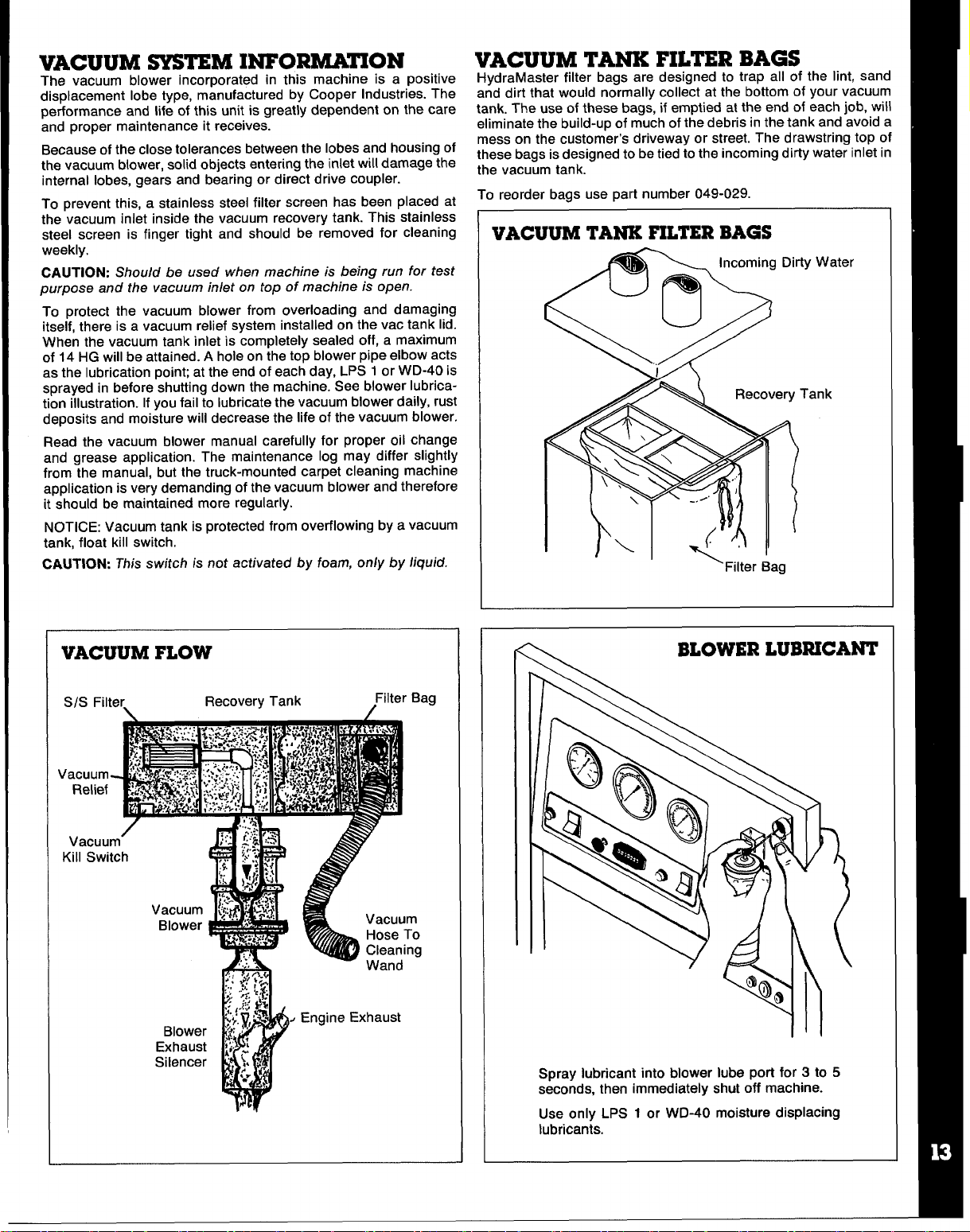
VACUUM SYSTEMINFORMATION
—
The vacuum blower incorporated in this machine is a positive
displacement lobe type, manufactured by Cooper Industries. The
performance and life of this unit is greatly dependent on the care
and proper maintenance it receives.
Because of the close tolerances between the lobes and housing of
the vacuum blower, solid objects entering the inlet will damage the
internal lobes, gears and bearing or direct drive coupler.
To prevent this, a stainless steel filter screen has been placed at
the vacuum inlet inside the vacuum recovery tank. This stainless
steel screen is finger tight and should be removed for cleaning
weekly.
CAUTION: Should be used when machine is be~ng run for test
purpose and the vacuum inlet on top of machine is open.
To protect the vacuum blower from overloading and damaging
itself, there is a vacuum relief system installed on the vac tank lid.
When the vacuum tank inlet is completely sealed off, a maximum
of 14 HG will be attained. A hole on the top blower pipe elbow acts
as the lubrication point at the end of each day, LPS 1 or WD-40 is
sprayed in before shutting down the machine. See blower lubrication illustration. Ifyou fail to lubricate the vacuum blower daily, rust
deposits and moisture will decrease the life of the vacuum blower.
Read the vacuum blower manual carefully for proper oil change
and grease application. The maintenance log may differ slightly
from the manual, but the truck-mounted carpet cleaning machine
application is very demanding of the vacuum blower and therefore
it should be maintained more regularly.
NOTICE: Vacuum tank is protected from overflowing by a vacuum
tank, float kill switch,
CAUTION: This switch is not activated by foam, only by liquid.
VACUUM TANK FILTBRBAGS
liydraMaster filter bags are designed to trap all of the lint, sand
and dirt that would normally collect at the bottom of your vacuum
tank. The use of these bags, if emptied at the end of each job, will
eliminate the build-up of much of the debris in the tank and avoid a
mess on the customer’s driveway or street. The drawstring top of
these bags is designed to be tied to the incoming dirty water inlet in
the vacuum tank.
To reorder bags use part number 049-029.
VACUUM TANK FILTER BAGS
ter
VACUUM FLOW
S/S Filter
\ /
Recovery Tank
Filter Bag
Spray lubricant into blower lube port for 3 to 5
seconds, then immediately shut off machine.
Use only LPS 1 or WD-40 moisture displacing
lubricants.
Page 15
1. All Sutorbilt California Series ‘F’ blowers are covered by this warranty.
2. Warranty period is 24 months from date of shipment, or 18 months from date of installation, whichever occurs first.
3. Sutorbilt will replace or repair any unit covered by this warranty without regard for the cause of failure.
4. Customers claiming relief under this warranty shall issue a Purchase Order to Sutorbilt for a replacement unit.
5. Customer must obtain a Return Goods Authorization number from the factory and return blower prepaid to an Authorized
Factory Repair Center, as directed.
6. On receipt of the blower a credit memo will be issued to offset the P.O. issued Der (4} above.
7. Replacement unit will be shipped to customer at Sutorbilt’s expense to any destination in the US or Canada.
8. SUTORBILT reserves the right to withdraw the Uncontested Warranty where evidence indicates application outside the
manufacturer’s stated performance area, or where there is evidence of abuse.
CONTACT SUTOR81LT FOR THE LOCATION OF THE
1
FACTORY AUTHORIZED SERVICE CENTER NEAREST YOIJ
.,
Ila
-.
1
ZJ
$puggyL;
~
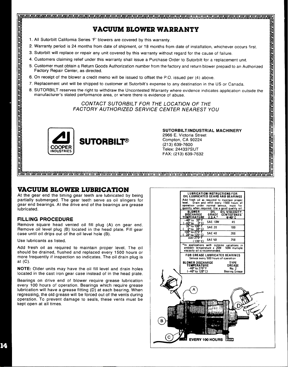
VACUUM BLOWER LUBRICATION
At the gear end the timing gear teeth are lubricated by being
partially submerged. The gear teeth serve as oil slingers for
gear end bearings. At the drive end of the bearings are grease
lubricated.
FILLING PROCEDURE
Remove square head vented oil fill plug (A) on gear end.
Remove oil level plug (B) located in the head plate. Fill gear
case until oil drips out of the oil level hole (B).
Use lubricants as listed.
Add fresh oil as required to maintain proper level. The oil
should be drained, flushed and replaced every 1500 hours or
more frequently if inspection so indicates. The oil drain plug is
at (C).
NOTE: Older units may have the oil fill level and drain holes
located in the cast iron gear case instead of in the head plate.
Bearings on drive end of blower require grease lubrication
Wery 100 hours of operation. Bearings which require grease
lubrication will have a grease fitting (D) at each bearing. When
regressing, the old grease will be forced out of the vents during
operation. To prevent damage to seals, these vents must be
kept open at all times.
=n m7fiC2~lL’”
1 wu E vnu
:lx
cc I
SUTORBILT/industrial MACHINERY
2966 E. Victoria Street
Compton, CA 90224
(213) 639-7600
Telex: 244337SUT
FAX: (21 3) 639-7632
LUBRICATION IN~RUCTiONSFOR
OILLUERICATEOGEARSAMOB~ARIR~S
Add fresh od m roqulmd to mamtam proper
Ieval. Dram cnd refill every 1500 hours oi
cmeratbon under normal kwice. more fm.
qbently when reqwred, U$e a good qualmy
BLOWER
OISCHARGE
TEhlPER+lTUBE
~!: %;, SAE1OW
%
W
over
=~!, SAE 50
‘In appficat(on$ w!th extreme varmt!om In
ambient temperature a 20w 50w mulrmle
viscosl~ oil ISrecommended.
FOR GREASE LUBRICATE EEARINGS
Sefwce every 500 houm of operatnon
OIL OILVISCOSl~~,
GRA#$ CENTISTOKES
F
SAE 20 100
c)
SAE 40 ?Iln
-,.,
)
o
45
250
1
Ott.
1
I
Page 16

VACUUM BLOWER TROUBLESHOOTING GUIDE
PROBLEM: Loss of Vacuum
Cause
Collapsed vacuum hose between blower and vacuum tank.
Clogged stainless steel filter.
Defective vacuum tank seal.
Defective or ‘open’ vacuum tank dump valve.
Fractured weld on vacuum tank.
Collapsed or kinked vacuum hose.
Plugged vacuum hose.
Restriction in cleaning tool.
Worn end plates or lobes in vacuum blower.
Loose drive shaft between clutch and blower.
PROBLEM: Blower is Seized
Cause
Rust.
Foreign matter.
NOTE: The above mentioned, rust, foreign matter and seizing are often caused from foam traveling through the blower.
Solution
Remove and replace hose. NOTE: A special reinforced hose
is reauired for replacement.
Remove and clean or replace stainless steel filter.
Remove and replace vacuum tank seal.
Close valve.
Replace valve.
Re-weld as required or replace tank.
Reshape hose if possible and/or eliminate kinks.
Remove obstruction by reversing the vacuum hose.
Remove obstruction.
Replace worn components. NOTE: Must be accomplished by
a qualified technician.
The set “screws may come loose causing blower to stand still
while engine may be turning properly. NOTE: Unless the
blower is seized or making a knocking noise, your vacuum
loss is not caused by a bad blower.
Solution
Spray rust dissolving lubricant onto lobes to emulsify rust and
attempt to rotate vacuum lobes.
Disassemble and remove foreign matter and repair as
required. NOTE: Disassembly must be accomplished by
aualified technician.
PROBLEM: Noise in Vacuum Blower
Cause
Worn Gears.
Lack of Lubrication. NOTE: Permanent damage may have
resulted from lack of lubrication.
Worn bearings.
Debris and/or foreign material build-up. NOTE: A stainless
steel filter is provided in vacuum inlet located in vacuum
blower components.
Loose or missina mountina bolts. Tiahten or reinstall mountina baits.
Solution
Remove and replace gears. NOTE: Replacement of gears
must be accomplished by a qualified technician.
Timing of vacuum blower has been changed due to worn
components. Replacement of components must be
accomplished by a qualified technican.
Lubricate as specified by applicable vacuum blower manual.
See index.
Remove and replace bearings as required. Must be
accomplished bv aualified technician.
Disassemble vacuum blower and remove foreign material.
NOTE: Disassembly should be accomplished by qualified
technician only. Replacement of worn parts is recommended is this procedure is necessary.
Page 17

HEATING SYSTEM INFORMATION
The propane heater incorporated in this equipment is a special
design for use in the carpet cleaning industry. It’s high pressure
coils and thermostatic temperature control make it simple to
operate and reliable. Once the desired temperature is set, the
heater will then go ‘on’ and ‘off’ according to the water temperature
within the heater. As water is used through the cleaning tool, cold
water entering the heater will activate the thermostatically controlled propane valve thereby firing the heater to maintain a con-
skitant flow of hot water. Cmce the cleaning wand is shut off and
the flow of water through the heater stops, the heater will continue
to burn until the set temperature is attained.
It is possible then with this design that the flame may be on when
the wand is off, likewise, it is possible the flame may be off when
the wand is on.
CAUTION: This heater is designed to burn vapor propane gas
only. ArJy liquid propane entering the heater may cause damage
to the control valve on the heater. it will also cause improper
burning and a soot build-up on the coils. Therefore, it is
necessary to shut off the heater and c/ose the valve at the tank
bet ween cleaning locations. Failure to do this allows sloshing li-
quid to enter the vapor feed line to the heater.
IMPORTANT Overfilling of the propane tank will cause many
problems. To avoid this, advise the attendant filling the tank not
to fill the tank over 80%. When filling the tank, watch the 10%
valve and immediately stop filling when white liquid starts spurt-
ing from th@ 10°4 valve. To prevent damage to the propane
regulator’, always close the vaive on the tank before filling.
The propane regulator is pre-set at the factory at 6 oz. of propane.
This reading is taken at the control valve on the heater (see figure
A -No. 6). To prevent road dust and moisture from entering the pro-
pane regulator, keep the white plastic cover (supplied) on the
regulator at all times.
To avoid restriction of air flow at base of heater, keep articles such
as chemical containers, hose, boxes, etc. from within 18 inches of
base of heater. NOTE: This restricted situation also creates an
over rich condition which results in soot build-up.
IMPORTANT If a new propane tank has been installed or hoses
have been disconnected, air may enter propane hoses and must
be purged prior to attempting to light the pilot burner. Should this
condition exist, operator must depress the pilot button for 1-5
minutes and attempt to ignite the pilot light at 15 second intervals.
A very slight hissing noise should be evident while performing this
operation.
CAUTION: Check heater for propane leaks regularly as loading
and unloading hoses, too/s, etc., may accidentally bump against
heater fittings or pipes.
HEATER- OPERATING INSTRUCTIONS
CAUTION: Heater must be fi//ed with water prior to igniting.
A. TO START PILOT
1. Adjust thermostat control knob on unitrol to desired setting.
2. Adjust upper dial to pilot position.
3. Depress pilot button.
4. Depress sparking button to light pilot.
IF PILOT FAILS TO LIGHT:
Is propane tank full?
Is propane tank valve open?
Has air been properly bled from propane line?
WHEN PILOT LIGHTS:
Wait ten seconds, depressing button manually, then release
button.
CAUTION: Always keep face away from main burner opening to
avoid ignition flash burn.
B. TO LIGHT MAIN BURNER:
1. Turn upper knob to “on” position. Flame will come on.
If you do not get the burner to flame, the pilot has expired. You
must turn upper dial to “off” position. Do not attempt to re-light
the pilot for 60 seconds. To light the main burner, repeat instructions as above (TO START PILOT), 1 through 4.
OR,
Water may already be at controlled temperature.
Flame will turn off when thermostat senses maximum
temperature.
C. TO ACHIEVE PROPER CARPET CLEANING
TEMPERATURE
1. Complete procedures A & B.
2. With 100’ of hose, turn cleaning wand on for 5 minutes and the
temperature should stabilize.
3. Once a constant temperature is established, turn cleaning
The flame on the heater burner should remain on for 10-15
‘off’.
seconds.
A. If the flame expires prior to 10 seconds, turn the thermostat
dial to a higher reading, then repeat C 1-3.
B. If the flame remains lit after 15 seconds, turn the thermostat
dial to a lower reading, then repeat C 1-3.
D. TO SHUT DOWN HEATER:
1. Turn upper dial #1 to ‘off’ position.
2. CAUTION: Turn cleaning wand on for 3 to 5 minutes to cool
heater core. If heater core is not cooled, it is possib(e that the
heat retained in the core will cause boiling back into a
chemical mix tank.
3. Close propane tank valve While wand IS on and heater w
cooling.
wand
PILOT BURNER ADJUSTMENT
1. Remove pilot adjustment cap #5.
2. Adjust pilot key to provide
properly sized flame.
3. Replace pilot adjustment cap.
Allen head pipe plug #6 can be
removed for monometer insertion
to read propane ounces.
@
@l’@
Page 18

HEATER TROUBLESHOOTING
PROBLEM: Excessive Heat
Flames Proturding Outside The Lower Openings
Cause lSolution:
1. Thermostatic control dial set too high.
A. Turn dial to lower setting.
2. Maladjustment of propane regulator. NOTE: Propane regulators
are factory preset and may be readjusted by authorized
personnel.
A. Contact manufacturer to determine correct procedure.
B. Have your local propane dealer use a monometer at the
unitrol to reset the propane regulator to 7 oz. maximum.
3. Overfilled propane tank. NOTE: Propane heater is designed to
operate on vapor propane only. Over-filling a propane tank
allows liquid propane to enter all heater related components
and permits an over-rich burning condition to occur. This condition usually requires the heater core to be cleaned of soot and
carbon deposits. Cleaning is a messy, dirty job and very
inconvenient, so don’t let it ha~~en to you!
PROBLEM: Pilot Light
Cause lSolution:
1. Pilot light will not ignite. NOTE: Do not use a needle or pin to
clean pilot orifice - use compressed air or solvent only.
A. Verify propane reaching igniter. NOTE: A kinked or crushed
hose may impede propane flow.
B. Remove and clean orifice.
C. Verify iqnitor spark is operating correctly.
CAT PUMP Model 290
OPERATING INSTRUCTIONS
CAUTION: CAT PUMPS are positive displacement pumps.
Therefore, a properly designed pressure relief mechanism MUST
be installed in the discharge piping. Failure to install such relief
mechanism could result in personal injury or damage to the pump
or system. Cat Pumps Corporation does not assume any liability or
responsibility for the operation of a customer’s high pressure
system.
SPECIFICA~ONS
Volume:3.5 GPM (13 L/M)
DischargePressure:1200 PSI (83 BAR)
MaximumInlet Pressure -8.5 to + 40 PSI (-0.6 to + 2.8
RPM: 1200 RPM (1200 RPM)
Bore: 0,787” (20mm)
Stroke 0.472” (12mm)
Crankcase Capacity: 10 oz. (.3 L)
Maximum Fluid Temperature: 180”F (71 “C)
Inlet Port (l): 1/2’: NPT (1/2” NPT)
Chemical Injection Port (1): 1/4” NPT (1/4” NPT)
Discharge Ports (2): 3/8” NPT (3/8” NPT)
(l): 1/2” NPT (1/2” NPT)
Pulley Mounting: Either side (Either side)
Shaft Diameter 0.650” (16.5mm)
Weight: 12.1 Ibs. (5.5 kg)
Dimensions: 10.77’’x9.O6’’XI.I 4“ (273,5 x230x130.5 mm)
BAR)
Products described hereon are covered by one or more of
the following U.S. patents: 3558244, 3652188, 3809508,
3920356, and 3930756
—-. _
JP*-*+
.3
CO RPOF7ATION
SS5 MINNEAPOLIS, MN 55440
PO. Box
Phone (612) 780.5440 – Telex 294276 Phone 0612.56000112 — Telex 41 ffi713
● N V CAT PuMPS INTERNATIONAL S.A. s
Harmonlestraat 29
S 2000 Antwerp, Belglum
Pho”e (03] 237.72.24 — Telex 33947
● CAT PUMPS — A,G.0
Loretohoehe 5
CH.6300 ZUG, Switzerland
Phone (42) 21.3140 — Telex S$5 160 cpag ch
9
CAT PuM’PS DEuTSCH LAND GmbH ●
Restocker SIrasse 9
6200 Wlesbaden.Blerstadt, West Germany
● CAT PUMPS (u.K ) LTO 9
27 StatIon Industrial Estate, Fleet
Hampshtre GU13 80Y, England
Phone Fleet 22031 — Telex S5SS9S
Page 19

CAT PUMP WARRANTY
This Cat Pump (“product”) is warranted by the manufacturer to
be free from defects in workmanship and material for one year
from date of manufacturer’s shipment. This warranty is limited
to repairing or replacing products which manufacturer’s in-
vestigation shows were defective at the time of shipment by the
manufacturer. All products subject to this warranty shall be
returned F.O.B. Cat Pumps Corp., Minneapolis, Minnesota
55430, U.S.A. for examination, repair or replacement.
The express warranty set forth herein is in lieu of all other war-
ranties, express or implied, includingwithout limitationany war-
ranties of merchantability or fitnessfor a particularpurpose and
all such warranties are hereby disclaimed and excluded by the
manufacturer. Repair or replacement of defective products as
provided above is the sole and exclusive remedy provided
hereunder and the manufacturer shall not be liable for any fur-
ther loss, damages or expenses, including incidental or conse-
quential damages, directly or indirectly arising from the sale or
use of this product.
This warranty is subject to the following warranty conditions:
Important Ccmditions
LUBRICATION - fill crankcase
per specifications with Cat Pump oil or equivalent SAE 40
to the top of oil gauge window
weight hydraulic oil with antiwear and rust inhibitor additives,
Change initial fill after 50 hour run-in period. Change oil every
three months or at 500 hour intervals thereafter. Prrrrrm-a-lube
seals need no lubrication. Blue dot seals and wicks must
receive three drops of Cat Pump oil per wick every 50 hours of
operation.
GOOD LUBRICATION IS THE EASIEST, MOST EFFICIENT
AND LEAST EXPENSIVE OF PREVENTATIVE
MAINTENANCE.
RPM and PRESSURE - Pump operation must be wltttin RPM
and pressure specifications. Pressure relief valve must be
installed.
DO NOT PUMP ACIDS OR ABRASIVE FLUIDS with this unit.
Consult Cat Pumps for additional information on questionable
fluids.
FREEZING CONDITIONS - Pump must be protected from
freezing conditions.
USE OF OTHER THAN CAT PUMP PARTS OR THEIR
EQUIVALENT
VC)IDS THE WARRANTY
GENERAL INFORMATION FOR CAT PUMP REPAIR
As you remove your discharge manifold, there is a set of 3 check
valves (which usually fall out during dis-assembly). If the surfaces
of these check valves are dirty, or show signs of chemical build-up,
it is probable that they would remain open causing pressure loss
or pulsation. Upon inspecting the valves, make sure that the teflon
buttons in the valve spring retainers are still intact. Also examine
the discharge manifold. Look for problems such as cracks,
chemical buildup or warpage due to freezing. If this discharge
manifold is warped, it will cause the check valves to stick and will
result in loss of pressure.
The Cat pump cups are often the source of pressure loss. Upon inspection they may appear melted or torn, but often they will look
goad. Replace them anyway. There is no sure method of visually
inspecting the cups. HydraMaster recommends changing cups
whether they look gaod or not.
Anytime your pump is being dismantled, HydraMaster recommends replacement of all ‘o’ rings and seals. This is merely a convenience to the customer to make sure that the Cat pump is in top
operating condition.
The prrm-a-lube seals located within the intake manifold will allow
air to enter the pump ifthey are worn. Again, it is difficult to visually
pinpoint a defective prrrm-a-lube seal. Replace them all.
Within the piston sleeve cylinders there are 6 ‘o’ rings that are
1/4 the size of a penny. If these ‘o’ rings are bad, water will be
about
pumped back into the oil. If this has occurred the oil will raise in
level and appear milky. If you are unable to repair seals right away,
change oil frequently. Repair the pump as soon as possible so as
to not damage bearing or connecting rods.
Repairing of Cat pumps is not a difficult task, However, before
disassembling make sure you have the proper parts required.
1 - short (or hot) cup kit 3- Prrrm-a-lube seals
6- piston sleeve ‘o’ rings
Read instructions thoroughly, supplied in the Cat pump manual,
prior to disassembly and follow directions as stated. Oil all seals
thoroughly prior to installation. (Remember, a newly scarred seal
is no better than one you just took out.)
1 - bottle Cat oil
Page 20

PISTON MODEL 290 Exploded View
PARTS LISTModel 290
ITEM PART NO. DESCRIPTION
1 20285 O-Ring (Buns-N) 1
2 44274 Crankcase 1
3 85660 Stud (M8
4 44377 O-Ring, Oil Filler Cap 1
5
8
9
10 43987 Bubble Oil Gauge 1
11
12
15
4R Aannd
,“ . . . . .
17 14467
18
19 26536
20
21
23
24
25
26 20017 Seal Washer 3
27 25301 Oil Seal 3
28 25327 Barrier Slinger 3
29 25392 O-Ring, SIeeva 3
30
31
32
33
34
44374
43340 O-Ring, Crankcase Cover 1
43339
23170
25625 Drain Plug
92520 Sems Comb Head Screw
Oil Filler Cap
Crankcase Cover 1
O-Ring, Drain Plug 1
(M6 x
Crankshaft
Rearing 2
~il Seal (Buns-N) 2
24159
27950
92519
101799
101800 Piston Rod
16946 Ptston Pin
28771 O-Ring, Sleeve (Viton) 3
u
)-Ring, Oil Seal Case 2
o
Oil Seal Case 2
Sems Comb. Head Screw
(M6x 16) 8
Connecting Rod 3
29003 Back-UpRing,Sleeve (Teflon) 3
29614 Sleeve (29743 Unchromed) 3
26854 Seal Washer 3
28597 Seal Retainer 3
25126 Inlet Manifold
25635
Inlet Manifold-StainlessSteel 1
X 62)
20) 6
QTY.
2
1
1
1
3
3
1
ITEM
35 30315
38
39 30543
40
41 43172
42
43
44 27006 Conical Washar-SS (M6)
45
46 14158 Cotterpin
47 101602
48
49 21985 Bat-Up Ring, Cylinder
50 24459 Discharge Manifold
51 43442 Valve Spring Retainer
52 43360 Valve Spring
53 43723 Valve
54 43434 Discharge Valve Seat
56 81109
57
58 25130
PART NO. DESCRIPTION
Prrrrrm-A-Lube Seal
30325
27004 Inlet Valve 3
30544
Prrrrrm-A-Lube Seal (Viton)
Bat-Cup Piston
Bat-Cup Ring (Teflon)
Cup (Viton)
43474
27983 Piston Spacer 3
27002 Piston Retainer 3
27000 Nut-SS (M6)
23172
11377 O-Ring, Cylinder (Viton)
25634 Discharge Manifold-S.S.
101804 Hex Flange Nut (M8)
Bat-Cup Assembly 3
Cylinder (43634 Unch) 3
O-Ring, Cylinder (Buns-N)
Hex Nut (M6)
Shaft Protector 1
Electrlc Clutch Assembly
59 152-005 Tapered Sleeve 1
60 077-005
61 036-005 6“ Electric Clutch
62 143-084
63
ii
174-004
174-0;8 Lock Washer (5/1 6 US)
Key, Electric Clutch
8-30 mm Socket H
Flat-Washer (5/16 US)
. . . . . .Iead Screw 1
Wry.
3
3
3
3
3
3
3
3
6
6
3
1
1
3
3
3
3
2
2
1
1
1
1
Page 21

PUMPING SECTION CUTAWAY
\
6ac-Cup
Piston Spacer
I /
/
Nut
078-001 cup Kit
3
cup
6 O-Ring, Cylinder
3 Cotterpin
1 Instruction Sheet
1
Cup Inserter
078-003 Seal Kit
30431
Prrrrrm-A-Lube Seal
3
3
Cotterpin
2
Abrasive Paper
1
Instruction Sheet
Sleeve and Seal Kit
Prrrrrm-A-Lube Seal
3
3
Barrier Slinger
3
Cotterpin
3
Sleeve
O-fling, Sleeve
6
1
Instruction Sheet
l-l
Cylinde~
I 11P
/
078-006 Valve Kit
3
;
3
3
1
30860
6
3
3
3
3
3
3
3
3
3
3
1
Bat-Cup Ring
/
iston
Piston Rod Sleev~
Valve Spring Retainer
Valve Spring
Valve
Valve Seat
O-Ring, Cylinder
instruction Sheet
Piston Kit
O-Ring, Cylinder
Back-Up Ring, Cylinder
Bat-Cup Piston
Bat-Cup Ring
cup
Piston Spacer
Piston Retainer
Conical Washer (M6)
Nut (M6)
Cotterpin
Inlet Valves
Instruction Sheet
SERVICING THE VALVE ASSEMBLIES
DISASSEMBLY
1. Remove the fasteners securing the discharge manifold to the
crankcase of the pump.
2. Support the discharge manifold and tap from the backside
and a soft mallet to separate from the crankcase and
gradually work free from cylinders.
3. Valve assemblies will remain in the manifold. Pump madt?ls
with the o-ring groove on the outside of the
require the assistance of a reverse pliers to remove th~
valve seat. The valve, spring and retainer will then fall out
when the manifold is inverted.
Pump models without the o-ring groove on the outside of the
valve seat permit the seat, valve, spring and retainer all to fall
out when manifold is inverted,
REASSEMBLY:
1, Place retainers in manifold chambers
2. Next insert spring into center of retainer
3. Inspect the valves for wear, ridges or pitting and replace if
necessary.
NOTE: Seating side of fiat valves maybe lapped on flat
face using 240 grit paper. Quiet valves due to their shape
must be replaced.
Insert valve over spring with recessed (dish) side down.
4
Next examine the seating surface of the flat valve seats and
lap with 240 grit paper ;r replace if evidence of excessive
wear. Quiet valve seats should be replaced if worn, Lap new
quiet valve and seat to assure positive seal.
5. Some pump models have o-rings and back-up rings on the
valve seat, Examine and replace if worn. Always lubricate
o-rings for ease of installation and to avoid damaging
elastomers.
NOTE: First install o-ring in groove on seat (towards seating
surface), then back-up ring.
NOTE: Models without outer groove on seat require the
o-ring to be placed on lip of retainer.
6. Insert valve seats into manifold chambers.
7
Position manifold back onto pump.
NOTE: Lubricate o-rings on cylinder and exercise caution
when slipping manifold over cylinders to avoid damaging
cylinder o-rings.
Replace fasteners and torque per specification chart.
8.
NOTE: Replace ali original shims when used. When new
manifold is used reshim pump.
CAUTION: When starting the pump, check to see (hat there IS ‘
no cylinder motion as this will cause premature failure of the
cylinder o-rings. Center cylinder motion can be eliminated by
switching with one of the end cylinders.
va!ve seat
sur-
Page 22

SERVICING THE PUMPING SECTION
DISASSEMBLY:
1.
Remove discharge manifold as described.
2.
Grasp cylinders by hand and with an up and down motion,
pull cylinders from inlet manifold.
3.
Remove cotterpin, nut, and washer from piston rod.
4.
Next remove retainer, spacer, and piston/cup assembly.
5.
Remove inlet valve.
REASSEMBLY:
1. Examine inlet valve surfaces for pitting, scale or grooves.
Reverse valve and sand inlet side of valve using 240 grit
paper for clean surface or replace if evidence of excessive
wear. Slip onto rod.
2. Examine piston seating surfaces and sand clean on flat surface using 240 grit paper. If extreme pitting or sharp edges,
replace piston.
3, Examine cup for wear, cracking, tearing or separation from
the piston. If worn replace and lubricate before installing on
piston.
NOTE CUP INSTALLATION: Wipe cup inserter with oil. Slip
bat-cup ring (when used) onto piston. Push cup over inserter and square with all surfaces. Faulty cup installation
causes premature cup failure.
4. Next replace piston spacer and retainer on rod.
5. Replace washer, thread on nut and torque per specification
chart.
NOTE: Always replace with new Stainless Steel Cotterpin
and turn ends under.
6. Examine cylinder walls for scoring or etching which causes
premature wear of cups and replace if worn.
7. Lubricate cylinder walls for scoring or etching which causes
premature wear of cups and replace if worn.
SERVICING SLEEVESAND SEALS
DISASSEMBLY:
1. Remove discharge manifold and piston assemblies as
described.
2. Remove inlet manifold containing seals.
3. Grasp sleeves and with a pulling and twisting motion remove
the sleeves from the piston rod.
NOTE: Grasp sleeve with pliers only if replacing worn sleeves,
as this procedure will mar the sleeves.
4. Next remove seal retainer.
5. Remove and examine o-rings and/or back-up rings on piston
rod for wear and replace.
REASSEMBLY:
1. Lubricate new o-rings and/or back-up rings and slip onto piston
rod. Install the first o-ring in the groove on the piston rod. Next
position back-up ring against the shoulder in front of the first
o-ring. Then install the second o-ring. Exercise caution as you
slip the o-ring over the thread end of the piston rod.
2. Examine sleeves for scoring or etching and replace. Immerse
sleeves in oil and carefully twist and push sleeve onto rod
(machined counter bore end first).
3. Next install seal retainers. If wicks are used, replace wicks,
thoroughly saturate with oil, place in seal retainer and install retainer.
4. Place inlet manifold on pair of clearance blocks with crankcase
side down and drive out old seals.
5, Invert inlet manifold with crankcase side up and instal new
seals. Lubricate circumference of seal and install Prrrrrm-ALube seal with garder spring down. If using blue dot seal, blue
dot should be facing up when installed.
6. Slip lubricated seal inserters onto piston rod ends, position inlet
manifold onto pump and remove seal inserters.
NOTE: Replace original quantity washers on studs before
replacing inlet manifold.
NOTE: Some models secure inlet manifold to crankcase.
Replace fasteners and torque per specification chart.
7. Reassemble piston assemblies and discharge manifold as
described.
SERVICING CRANKCASE SECTION
1. While inlet manifold, sleeves and seal retainers are removed,
examine crankcase seals for wear.
2. Check oil level and for evidence of water in oil.
3. Rotate crankshaft by hand to feel for smooth bearing
movement.
4. Examine crankshaft oil seal externally for drying, cracking or
leaking.
5. Consult factory or your local distributor if crankcase service is
evidenced.
Page 23

CAT PIMP TROIUBLESHOOTING GUIDE
PROBLEM: Pulsation
Cause Solution
Debris in discharge valves of pump. Clean or replace discharge valves.
FITOBLEM: Low Pressure
cause Solution
Worn nozzle. Replace nozzle, of proper size.
Belt Slippage.
Air ieak in inlet plumbing. Disassemble, reseal, and reassemble.
Pressure gauge inoperative or not registering accurately. Check with new gauge; replace worn or damaged gauge,
Relief valve stuck, partially plugged or improperly adjusted;
valve seat worn.
Inlet suction strainer clogged or improper size. Clean. Use adequate size. Check more frequently.
Worn piston assembly. Abrasives in pumped fluid or severe install proper filter, Suction at inlet manifold must be limited
cavitation. Inadequate water supply.
Fouled or dirty inlet or discharge valves. Clean inlet and discharge valve assemblies.
Worn inlet or discharge valves. Replace worn valves, valve seats.
Leaky discharge hose. Replace discharge hose.
PROBLEM: Pumps runs extremeiy rough, pressure very iow
Cause
Restricted inlet or air entering the inlet plumbing.
Inlet restrictions andlor air leaks. Damaged cup or stuck inlet Replace worn cup or cups, clean out foreign material, replace
or discharge valve.
Wom inlet manifold seals. Replace worn seals.
Tighten or replace: use correct belt.
P.N. 06090
Clean, and adjust relief valve; check for worn and dirty valve
seats. Kit available.
to lifting less than 20 feet of waer or -8.5 PSI vacuum.
Soiution
Proper size inlet plumbing; check for air tight seal.
worn valves.
—
—
PROBLEM: Cylinder O-rings blown next to discharge manifold
Cause
Pressures in excess of rated PSi.
Warped manifold. Replace manifold.
PROBLEM: Leakage at the cyiincfer O-rings at the discharge manifold and black, powdery substance in the area af the
O-rings
cm.lse Solution
Loose cyiinders, Cylinder motion caused by improper
shimming of the discharge manifold. - many shims or the ears of the manifold will be bowed
PROBLEM: Water leakage from under the inlet manifold
Cause Solution
Worn inlet manifold seals. Leaking sleeve O-ring.
PROBLEM: Oii ieak between crankcase and cwm~ina section
Cause
Worn crankcase Diston rod seals.
Excess oii from wicks.
PI?OHLEM: (Iii leaking in the area of Crankshaft
Cause
Worn crankshaft seal or improperly installed oil seal retainer
packing.
Bad bearing,
Soiution
Check for plugged nozzle, closed valves or improperly
adjusted by-pass valve.
Remove spacer shims on manifold studs. Do not remove too
when the manifold is retightened, causing looseness in
the center cylinder.
Install seals. [f piston rod sleeves are scored, replace sleeves
and sleeve O-rings.
Solution
RerNace crankcase Diston rod seals.
Reduce quantity of oil per oiling.
Soiution
Remove oil seal retainer and replace damaged gasket andlor
seals.
Replace bearing.
Page 24

PROBLEM: Excessive play in the end of the crankshaft pulley
Cause
Worn main ball bearing from excessive tension on drive belt.
PROBLEM: Water in crankcase
Cause
May be caused by humid air condensing into water inside the
crankcase.
Leakage of manifold inlet seals and/or piston rod sleeve
PROBLEM: Oil leaking from underside of crankcase
Cause
Worn crankcase piston rod seals.
PROBLEM: Oil leaking at the rear portion of the crankcase
Cause
Damaged or improperly installed oil gauge or crankcase rear
cover O-ring, and drain plug O-ring.
PROBLEM: Oil leakage from drain plug
Cause
Loose drain plug or worn drain plug O-ring
PROBLEM: Loud knocking noise in pump
Cause
Pulley loose on crankshaft.
Broken or worn bearing.
Solution
Replace ball bearing. Properly tension belt.
Solution
Change oil at 3 month or 500 hour intervals using Cat Pump
Crankcase Oil (other approved oil every month or 200
hours) P.N.: 06100.
Replace seals, sleeve and O-rings.
Solution
Replace seals, sleeve and O-rings.
Solution
Replace oil gauge or cover O-ring, and drain plug O-ring.
Solution
Tighten drain plug or replace O-ring.
Solution
Check key and tighten set screw.
Replace bearings.
PROBLEM: Frequent or premature failure of the inlet manifold seals
Cause
Scored rods or sleeves.
Over pressure to inlet manifold.
Solution
Replace rods and sleeves.
Reduce inlet pressure per instructions.
PROBLEM: Short cup life
Cause
Damaged or worn chrome plating of the cylinders.
Abrasive material in the fluid being pumped.
Excessive pressure and/or temperature of fluid being pumped.
Solution
Replace cylinders.
Install proper filtration on pump inlet plumbing.
Check pressures and fluid inlet temperature; be sure they
are within specified range.
Over pressure of pumps.
Running Pump dry.
Front edge of piston sharp.
Chrome plating of cylinders damaged causing excessive wear
of cups. May be caused by pumping acid solution.
Reduce pressure.
Do not run pump without water.
Replace with new piston.
Install new cups and cylinders. Pump only fluid compatible
with chrome.
PROBLEM: Strong surging at the inlet and low pressure on the discharge side
Cause
Foreign particles in the inlet or discharge valve or worn inlet
and/or discharge valves.
Solution
Check for smooth lap surfaces on inlet and discharge valve
seats. Discharge valve seats and inlet valve seats may be
lapped on a very fine oil stone; damaged cups and
discharae valves cannot be
laDDf?d but must be reDlaced.
Page 25

HYDW-CAT ELECTRICAL SYSTEM
The entire electrical system operates on 12 volts DC which is provialed by a battery. Battery levels are sustained by a 15 amp alternator designed within the engine.
Pf?Of3LEM: Low Battery Voltage
Cause
Defective battery.
Corroded battery terminals.
Low battery fluid.
Loose wiring within electrical system.
Electrical short in wiring system.
ground connection.
Poor
PROBLEM: Inoperative Hour Meter
cause
Time is not advancing correctly.
NOTE: When new battery is installed insure it is properly charged
before installation or damage to the charging regulator may occur.
Solution
Remove and replace.
Clean terminals and battery posts.
Add water to appropriate level.
Examine all terminal connections and verify that they are
secure.
Examine electrical systems for bare wires.
Examine terminal and remove corrosion if necessary,
Solution
Verify 12 volts DC is available at the hour meter with the
ignition switch turned on. This can be accomplished with
a volt meter or a test lamp.
Remove and replace hour meter if 12 volts is available.
A nylon gear within the clock may have been jammed due to
a sudden jolt of the machine or truck. You may try simply
tapping on the meter to try to free the nylon gear,
Z
=
$
$
JIJ*
m
,:.. .
,,,.
(?!)%?
Fuel
HYDRA-CAT
S/Series
~
-.. .
1% z’”
w
Voltage Reg
Starter
Solenoid
..$...
,**V = :‘YE ‘“~ecovery
Red/White
‘ed Mix Tank
$?V* ‘“
.
“ Guard
Pump
Cut-Off Switch
P
I I Tank Cut-Off
)
~Jswi’ch””- -
HYDRA-CAT
M/Series
Engine Kill
s witch
T
I
uV_--43-l~oi,,r.ssur.
w
Switch
Page 26

CCKB ENGINE SERVICEGUIDE
Onan Model
HydraCat S/Series
SPECIFICATIONS
Engine Design: Opposed two cylinder, four cycle, L head and air
cooled
Bore: 3Vi” (82.55 mm)
Stroke: 3“ (76.20 mm)
Displacement: 49.6 cu inch (616,22 ems)
H.P. - Garden Tractor Service: 191/2 hp at 3600 rpm; 20 hp max. at
3900 rpm
Oil Capacity with Filter Changa: 4 qts. (3.78 lit)
Oil Capacity without Filter Change: 3% qts. (3.31 lit)
Tune-Up Specifications
Spark Plug Gap (Gasoline): .025 (0.69 mm)
Spark Plug Gap (LPG): .018 (0,46)
Breaker Point Gap: .020 (0.51 )
Valve Lash:
Intake: .008 to .008 (0.152 to 0.203 mm)
Exhaust: .015 to .017 (0.381 to 0,432 mm)
Ignition Timing:
Standard Electric Start (Stopped or Running) 200BTC
Manual Start with Spark Advance: 1“ATDC (Stopped)
Electric Start with Magneto and Spark Advance 5° (Stopped)
Engine Model Reference
Identify your model by referring to the MODEL and SPEC
(specification) NO. as shown on the unit nameplate. Always use
this number and the engine serial number when making reference
to your engine.
How to interpret MODEL and SPEC NO.
CCKB - MS I 2853 J
TTTT
1
1. Factory code for general identification purposes.
2. Specific Type
S - MANUAL STARTING
MS - ELECTRIC STARTING
3. Factory code for optional equipment supplied,
4. Specification (Spec Letter) advances with factory production
modification.
If your engine needs service or repair, contact an Onan Service
Center. Trained mechanics will assure expert repair service on
your Onan engine.
2
24”BTC (Running)
24°BTC (Running)
34
OUT OF SERVICE PROTECTION
Protect an engine that will be out-of-service for more than 30
days as follows:
1. Run engine until thoroughly warm (5 to 10 minutes).
2. Turn off fuel supply and run until engine stops.
3. Drain oil from oil base while still warm. Refill and attach a
warning tag stating oil vicosity used.
4. Remove spark plugs. Pour one ounce (two tablespoons) of
rust inhibitor (or SAE #50 oil) into the cylinders. Crank
engine over a few times. Install spark plugs.
5. Service air cleaner.
6. Clean governor linkage and protect by wrapping with a clean
cloth.
7. Plug exhaust outlet to prevent entrance of moisture, dirt,
bugs, etc.
8. Wipe entire unit. Coat rustable parts with a light film of grease
or oil.
9. Provide a suitable cover for the entire unit.
10. If battery is used, disconnect and follow standard battery
storage procedure.
WARNING: Carbon monoxide is an odorless, colorless gas formed
by incomplete combustion
is a dangerous gas that can cause unconsciousness and is poten tially lethal. Some of the symptoms or signs of carbon monoxide
inhalation are:
● Dizziness
● Intense Headache
● Weakness and Sleepiness
● Vomiting
● Muscular Twitching
o Throbbing in Temples
If you experience any of the above symptoms, get out into fresh air
immediately.
The best protection against carbon monoxide inhalation is
inspection of the complete exhaust system, If you notice a change in
the sound or appearance of exhaust system, shut the unit down
immediately and have it inspected and repaired at once by a
competent mechanic.
Before Starting
Check the engine to make sure it has been filled with oil and fuel.
The chart below lists oil andfuet-recomrnendeticrns.
CRANKCASE OIL: Fil the crankcase with a good quality oil that
meets the API (American Petroleum Institute) service designation
SE or SE/CC. Recommended oil numbers for expected ambient
temperatures are as follows:
TEMPERATURE GRADE
Below O°F (18°C)
Below 32°F (O”C)
Above 32°F (O°C)
Fill to “Full” mark on dipstick.
CAUTION: Do not overfill crankcase. Do not use service DS oil.
Do not mix brands nor grades of motor oil.
Refer to Periodic Service section for recommended oil change
intervals.
RECOMMENDED FUEL Use clean, fresh, non-leaded or regular
grade, automotive gasoline. Do not use highly leaded premium
types.
For new engines, the most satisfactory results are obtained by
using nonleaded gasoline. For older engines that have previously
of hydrocarbon fuels. Carbon monoxide
a regular
SAE 5W30
SAE 5W30 or 10W40
SAE 30
Page 27

used leaded gasoline, heads must be taken off and all lead
deposits removed from engine before switching to nonleaded
gasoline.
WARNING: Never check oil level while errgirre is running. Hot oil
discharged from the engine could cause personal injury.
Cap and oil level
indicator
Keep oil
at this level _- __~
T
Never operate ------
engine with oil
below this level
r
Crankcase Oil Fill
CAUTION: If lead deposits are not removed from engine before
switching from leaded to nonieaded gasoline, preignition cou/d
occur, causing severe damage to the engine.
WARNING: Never fill the fuel tank when the engine is running.
Gasoline could ignite, causing a serious injury.
INSPECTION: Inspect the engine visually before starting. Check
for loose or missing parts and any damage which may have
occurred in shipment.
Always replace cap
tightly, or oil
leakage may occur
FULL
LOW
STARTING
If your engine has a START-RUN-STOP switch, press switch
toggle to START, then release to RUN when engine starts. Press
toggle to STOP, to stop engine.
1. Turn on ignition switch, pull the choke lever way out (for a cold
engine) and push the start switch. When the engine starts,
gradually push the choke lever in until the engine runs smoothly.
2. Black smoke from the exhaust and a rough running engine
usually indicate over-choking.
3. To stop engine, turn ignition switch to off position.
OPERATION
Break-in Procedure
Controlled break-in with proper oil and a conscientiously applied
maintenance program will help assure satisfactory service for
many hours from your Onan engine.
Break-in or ideal fitting of all internal moving metal parts can best
be achieved by maintaining proper cooling and correct lubrication
during the running-in period. Run the engine at about half load for
the first three hours with intermittent periods of full load to control
engine break-in. Engine damage can be caused by using the
wrong grade and weight of oil and high engine operating
temperatures during break-in.
Check the oil level at least every five operating hours. Add oil to
keep it at the proper level, but never overfill as overfilling may
cause the oil to foam and enter the breather system.
Hot Weather Operation
When operating the engine in temperatures above 75°F (24° C)
pay particular attention to the following items to prevent damage:
1. Keep the engine cooling fins clean and free of obstruction which
would decrease air flow to and from the engine.
2. See that nothing obstructs air flow to and from the engine.
3. Ensure that you are using the proper grade and weight of oil for
the temperature the engine is being used in. Check the oil level
each time you fill the fuel tank.
4. Check the battery water level more frequently than every 50
hours which is recommended under normal conditions. High
temperatures cause faster evaporation.
Cold Weather Operation
When the engine is being used in temperatures below 32°F (0° C),
check the following items closely:
1. Use the correct grade and weight of oil for the temperature conditions. Change the oil only when the engine is warm. tf an unexpected temperature drop occurs when the engine is filled with
summer oii, move to a warm location until the oil will flow freely
before starting the engine.
2. Use fresh fuel. Fill the fuel tank after each days use to protect
against moisture condensation.
3. Keep battery in a well-charged condition,
MAINTENANCE
OIL LEVEL Check oil level at least every eight hours of operation.
Check more frequently on a new or overhauled engine as oil consumption is higher until piston rings seat properly,
OIL CHANGE: Change crankcase oil after the first 2.5 hours of
operation; change every 50 hours after that. if operating in extremely dusty conditions, change oil more frequently.
OIL FILTER (If used): Replace oil filter every 100 hours; replace
more often in dusty conditions. Tighten the filter finger-tigh! plus
one quarter to one half turn. Be sure to replace rubber ring around
filter.
CRANKCASE BREATHER: This engine uses a crankcase
breather vaive for maintaining crankcase vacuum, No
maintenance is generally required. If the crankcase becomes
pressurized as evidenced by oil leaks at the seals, clean the
crankcase breather cap and valve assembly, and the breather
tube baffle in suitable solvent. To remove breather cap and valve
assembly, remove the breather hose clamp and breather tube
clamp.
MOISTENED FOAM AIR CLEANER: This air cleaner consists of a
synthetic sponge over a metal retainer. The base and cover are
similar to those of the dry paper kind. Wash the sponge periodically, moisten in oil and squeeze dry.
COOLING SYSTEM: Check and clean cooling fins at least every
50 hours. Remove any dust, dirt or oil which may have accumulated.
CAUTION: Plugged or clogged cooiing fins can cause
overheating and engine damage.
SPARK PLUGS: Check, clean and reset spark plugs every 100
operating hours. Replace spark plugs that show signs of fouling or
electrode erosion. Replace plugs every 250 operating hours.
BREAKER POINTS: Check, clean and reset breaker points every
200 operating hours. Replace points if they are pitted or burned.
See ADJUSTMENT section.
Page 28

Spark Plug Gap
Spark Plug Gap 0.025”
Oil Filter
Page 29

ADJUSTMENTS
CARBURETOR
The carburetor has an idel jet and a main jet. The idle jet which is
adjustable, effects engine operation at low speed. The main jet
usually affects operation under load (high speed). Under normal
circumstances, factory carburetor adjustments should not be
disturbed. If the idle adjustment has been disturbed, turn the
needle (counterclockwise) off its seat 1 to 11/2turns to permit starting the engine, then readjust as follows:
Carburetor Idle Adjustment
1. Allow the engine to run at least 10 minutes to warm it up.
2. Turn the idle needle out (counterclockwise) until engine begins
to slow down or run unevenly. Remember this position.
3. Turn needle in (clockwise) past the position where the engine
runs smoothly until it begins to slow down or run unevenly.
CAUTION: Do not force the need/e against its seat; doing so
will damage it.
4. Back the needle out to
between the two positions. This should provide a smooth running idle.
CAUTION: Loosen the packing nut before making main fue/ ad-
justment and then tighten the nut to a snug fit after the adjustment
has been made. This procedure makes it easier to use the
carburetor adjusting tool and prevents fuel leaks around the
packing nut. Fuel leaks cause hard starting because the float
level become 10wer than normal.
Idle Spe
a position approximately halfway
Fuel
Adjustment
BREAKER POINTS
To maintain maximum efficiency from the engine, check condition
of the beaker points every 200 hours of operation, Proceed as
follows:
1,
Remove the two screws and the cover on the breaker box.
2.
Remove both spark plugs so engine can be easily rotated by
hand. If plugs have not bee changed within the last 100 hours,
clean and regap or replace them with new ones after setting the
breaker points.
Remove the two mounting screws (A) and pull the points out of
3.
the box just far enough so screw (B) can be removed. Replace
points with a new set (if needed) but do not completely tighten
mounting screws (A),
4.
Rotate the engine clockwise (facing flywheel) by hand until TC
mark on gear cover aligns with TC mark on flywheel, Turn screw
(C) until point gap measures .020” (0.508 mm) with a flat
thickness gauge.
Tighten mounting screws and recheck gap.
5.
Reference
Approximate Timing
for
Breaker Point Adjustment
/
.
Loosen Screws
and shift box
To ADVANCE or RETARD ,
Packing Nut
‘~7
Carburetor Adjustments
Carburetor Main (Load) Adjustment
If engine runs unevenly at half or full load due to faulty carburetion,
the main adjusting needle needs readjustment. For initial start-up,
turn main adjustment 1 to 1
1.
Wart engine arrd allow it to warm up.
2.
Set idle adjustment so engine runns smoothly.
Release governor mechanism to allow engine to accelerate. If
3.
engine accelerates evenly and without hesitation, main adjustment is correct. If not, turn needle outward about 1/2 turn and
again slow the engine down and relase the mechanism. Continue until the engine accelerates evenly and without hesitation
after relasing the governor.
4,
If engine tends to hunt (alternate increase and decrease of
speed), open the main adjusting needle a little more. Do not
open more than 1/2 turn beyond the maximum power point.
V2 turns (counterclockwise) off its seat.
Main Fuel Adjustment
ENGINE SAFETY PRECAUTIONS
It is recommended that you read your engine manual and become
thoroughly acquainted with your equipment before you start the
engine.
WARNING: This symbo/ is used through th;s manual to warn of
possib/e serious personal injury.
CAUTION: This symbol refers to possible equipment damage.
Fuels, electrical equipment, batteries, exhaust gases and moving
parts present potential hazards that could result in serious,
personal injury. Take care in following these recommended procedures.
Safety Codes
● All local, state and federal codes should be consulted and com-
plied with.
General
o Provide appropriate fire extinguishers and install them in conve-
nient locations. Use an extinguisher rated ABC by NFPA.
● Make sure that all fasteners on the engine are secure, Tighten
supports and clamps, keep guards in position over fans, driving
belts, etc.
o If it is necessary to make adjustments while the engine is runn-
ing, use extreme caution when close to hot exhausts, moving
parts, etc.
Protect Against Moving Parts
* Do not wear loose clothing in the vicinity of moving parts, such
as PTO shafts, flywheels, blowers, couplings, fans, belts, etc.
* Keep your hands away from moving parts.
Page 30

Batteries
● Before starting work on the engine, disconnect batteries to pre-
vent inadvertent starting of the engine.
● DO NOT SMOKE while servicing batteries. Lead acid batteries
give off a highly explosive hydrogen gas which can be ignited by
flame, electrical arcing or by smoking.
● Verify battery polarity before connecting battery cables. Connect
negative cable last.
Fuel System
● DO NOT fill fuel tanks while engine is running, unless tanks are
outside engine compartment.
“ DO NOT smoke or use an open flame in the vicinity of the engine
or fuel tank. Internal combustion engine fuels are highly flammable.
* Fuel lines must be of steel piping, adequately secured, and free
from leaks. Piping at the engine should be approved flexible line.
Do not use copper piping on flexible lines as copper will work
harden and become brittle enough to break.
● Be sure all fuel supplies have a positive shutoff valve.
Exhaust System
● Exhaust products of any internal combustion engine are toxic
and can cause injury, or death if inhaled. All engine installations,
especially those within a confine, should be equipped with an exhaust system to discharge gases to the atmosphere.
● Do not use exhaust gases to heat a compartment.
● Make sure that your exhaust system is free of leaks. Ensure that
exhaust manifolds are secure and are not warped by bolts
unevenly torqued.
Cooling System
● Coolants under pressure have ahigher boiling point than water.
DO NOT open a radiator pressure cap while the engine is running. Bleed the system pressure first.
Keep the Unit and Surrounding Area Clean
● Make sure that oily rags are not left on or near the engine.
● Remove all oil deposits. Remove all unnecessary grease and
oil from the unit. Accumulated grease and oil can cause
overheating and subsequent engine damage and may present a potential fire hazard.
PERIODIC SERVICEGUIDE
Regularly scheduled maintenance is the key to lower operating
costs and longer service life for the unit. The following schedule
can be used as a guide. However, actual operating conditions
under which a unit is run should be the determining factor in
establishing a maintenance schedule. When operating in very
dusty or dirty conditions, some of the service periods may have to
be reduced. Check the condition of the crankcase oil, the filters,
cooling fins, etc. frequently until the proper service time periods
can be established.
For any abnormalities in operation, unusual noises from engine or
accessories, loss of power, overheating, etc., contact your nearest
Onan Service Center.
PERIODIC MAINTENANCE SCHEDULE
Service These Items
Inspect Engine Generally
Check Oil Level
Service Air Cleaner
Change Crankcase Oil
Check Battery Electrolyte Level
Clean Cooling Fins x
Clean and Regap Spark Plugs
(Replace at 250 hours)
Replace Oil Filter
Clean Breather Valve
I Check Breaker Points
I Replace Air Cleaner Element
Check Valve Clearance
Remove Carbon and Lead Deposits
Irwmect Valves. Grind If Necessarv
.
Complete Reconditioning (If Required)
XI - Perform more often in extremely dusty conditions.
X2- For detailed maintenance, contact art .C)nanService Center.
X3- Check for fuel leaks, exhaust leaks, etc.
8
x3
I
x
I
I
I
1
I
I
1
After Each Cycle of Indicated Hours
50
100 200
I
400
xl
xl
x
xl
x
x
xl
1000
x2
x2
x2
x2
Page 31

KOHLERENGINE SEEVICE GUIDE
Magnum Model M20
HydraCcd M/Series
SPECIFICATIONS
General
Horsepower (~ 3,600 rpm): 20
Displacement (cu. in.): 46.98
Bare: 3.12
Stroke: 3.06
Compression Ratio: 6.6:1
Approx. Weight (lb.): 130
,4pprox. Oil Capacity’ (U.S. Quarts): 1.5
*For best results, fill to “F” mark on dipstick as opposed to adding
a given quantity of oil. Always check level on dipstick before
adding more oil. On engines equipped with oil filter, an additional
1/2 U.S. pint of oil is required when oil filter is replaced.
Valves and Tappets
Intake Valve to Tappet Clearance - Cold: .003/.006
Exhaust Valve to Tappet Clearance - Cold: .016/,019
Intake Valve Minimum Lift - Zero Lash: .274
Exhaust Valve fdinimum Lift - Zero Lash: .274
Intake Valve Minimum Stem 0.0.:.3103
Exhaust Valve Minimum Stem O.D.: .3086
Nominal Valve Seat Angle 45°
Valve Guide Reamer Size: .3125
Intake Valve Guide I.D. Max. Wear Limit: .007
Fuel Recommendations
WARNING: Explosive Fuels! Gasoline is extremely flammable,
and its vapors can explode if ignited. Store gasoline
proved containers, in well-ventilated, unoccupied buildings, away
from sparks
running since spilled fuel could ignite if it comes in contact with hot
parts or sparks from ignition. Do not start engine near spilled fuel;
wipe up spills immediately. Never use gasoline as a cleaning
agent.
For best results, use only clean, fresh, regular-grade, unleaded
gasoline with a pump sticker octane rating of 87 or higher. In countries using the Research method, it should be 90 octane minimum.
Unleaded is recommended since it leaves less combustion
chamber deposits. Regular-grade, leaded gasoline may also be
used; however, be aware that the combustion chamber and
cylinder head will require more frequent service. Refer to the
“Periodic Maintenance” section.
or flames. Do not fill fuel tank while the engine is hot or
only in ap-
Always use fresh gasoline. Fresh gasoline is blended for the
season and reduces gum deposits which could c[og the fuel
system. Do not use gasoline left over from the previous season.
Do not add oil to the gasoline,
Keep the vent hole in fuel tank cap open. If vent hole is plugged,
pressure may build up
dangerous spraying of gasoline when tank cap is removed. A
vacuum may also be created during operation which could stop
fuel flow to the carburetor.
in tank, causing carburetor flooding or
PERIODIC MAINTENANCE KOHLER
ENGINE
Required Maintenance
These required maintenance procedures should be performed at
the frequency stated in the table:
Required Maintenance
Check Oil Level . . . . . . . . . . . . . . . . . . . . ,.. ,,, ,., ... ,Daily. Daily
Clean Grass Screen............,,, . . . . . . . . . . . . . . . . . . .. Daily*
Check/Replace Fuel Filter. . . . . .As Required
Change Oil and Filter ., .As Specified in “Oil Change
Clean Foam Precleaned . . . . . . . . . . . . . . . . . . . . . . . .. fours” l-fours”
Clean Cooling Fins and External Surfaces .50 Hours”
Clean Paper Air Cleaner Element . . ..100 Hours”
Check Spark Plugs . . . . . . . . . . . . . . . . . . . . . . . . . . . . . . ..100 Hours
Check Valve-To-Tappet Clearance ., . . . . . . . . . . . ...500 Hours
Clean Cylinder Heads and Combustion Chambers . ..500 Hours””
Service Starter Motor Drive. .Annuailyor 500 Hours
‘Perform these maintenance procedures more frequently when
engine is operated under extremely dusty and dirty conditions.
“250 Hours when leaded gasoline is used.
WARNING: Accidental Starts! Before servicing the engine or
equipment, always remove the spark plug leads to prew.?nt the
engine from starting accidentally. Ground the leads to prevent
sparks that could cause fires.
.
Frequency
Intervals” Table
OIL
Oil Filter
Some engines are equipped with an oil filter. Replace the oil filter
every othw oil change, in accordance with the “iOilChange intervals” table. Always use a genuine Kohler replacement oil filter,
Check Oil Level
The importance of checking and maintaining the proper oil level in
crankcase cannot be overemphasized. Check oil BEFORE EACH
USE as follows:
1. Make sure the engine is stopped, level, and is cool so the oil has
had time to drain into the sump,
2. Clean the area around dipstick before removing to keep dirt,
grass clippings, etc., out of the engine.
3. Remove dipstick and wipe oil off. Reinse~ dipstick and push it
all the way down into tube. Remove dipstick and check the level.
The oil level should be up to, but not over, the “F”’ mark on the
dipstick. Refer to Figure 1.
01 F
Range
Operating
Range
--L-
L
Ii!i
Figure 1. Oil Level Range
Page 32

4. Add the proper type of oil if the level is low. Always check the
level with dipstick before adding more oil.
CAUTION: Never operate the engine with the oil level below “L”
mark or over “F” mark on dipstick.
Oil Sentry’M
m
Some engines are equipped with optional Oil Sentry oil pressure
monitor. Oil Sentry will either stop the engine or activate a “low oil”
warning light, if the oil pressure gets low. Actual Oil Sentry use will
vary depending on the engine application.
CAUTION: Oil Sentry is not a substitute for checking oil level
BEFORE EACH USE. Make sure the oil level is maintained up to
the “F” mark on dipstick.
Change Oil
For new engine, change oil after the first 5 hours of operation.
Thereafter, change oil as specified in the “Oil Change
Intervals” table.
For an overhauled engine or those rebuilt with a new short-
b/ock, use straight 30-weight Service Class SF oil for the first 5
hours of operation. Change the oil after this initial run-in period.
Thereafter, change the oil as specified in the “Oil Change intervals” table.
Drain oil while the engine is still warm from operation. The oil
will flow more freely and carry away more impurities. Change oil
as follows:
1. Remove the oil drain plug and dipstick. Refer to Figure 2. Tilt the
engine slightly towards the drain hole to obtain better drainage.
2. Reinstall the drain plug. Make sure it is tightened securely.
3. Fill with new oil of the proper type to the “F” mark on the
dipstick. Always check the” Ieve-l”on dipstick before adding
more oil. Make sure the engine is level when filling and
checking oil.
Change Oil Filter
Change the oil filter every other oil change, in accordance with
the “Oil Change Intervals” table. Always use a genuine Kohler
oil filter and change as follows:
1. Drain crankcase oil, then remove old filter.
2. Before installing replacement filter, apply a thin coating of oil
on surface of the rubber seal.
3. Turn filter clockwise until rubber seal contacts the filter
adapter, then tighten the filter an additional turn.
4. Add an additional 1/2 pint of oil for the filter capacity.
5. Start the engine and check for and correct any oil leaks,
AIR SYSTEM
Service Air Cleaner
Magnum engines are equipped with a high-density paper air
cleaner element. Some specifications are also equipped with an
oiled foam precleaned which surrounds the paper element. Refer to
Figure 3.
Also refer to the “Air Cleaner” section for disassembly and
reassembly procedures for all styles of air cleaners used on
these engines.
Precleaned
If so equipped, wash and reoil the precleaned every 25
operating hours (more often under extremely dusty, dirty
conditions).
1. Remove precleaned from paper element. Wash the
precleaned in warm water with detergent.
2. Rinse precleaned thoroughly until all traces of detergent are
eliminated. Squeeze out excess water (do not wring). Allow
precleaned to air dry.
Base Element
\
Cover Seals
Element Cover
/
Figure 2. Oil Filter, Oil Drain Plug Location
OIL CHANGE INTERVALS
Temperature
I
ABOVE
32°F (O°C)
BELOW
320F (Ooc)
I
“25 hours for continuous andlor heavy duty operatfon
SAE 30
Multwmcosny
Multiwscosity
I
Oil
Type
Engine Type Interval
With Filter 50 Hours”
Without Filter 25 Hours
WKh Filter
Without Ftlter 25 Hours
With Filter
Without Filter 25 Hours
t
25 Hours
50 Hours
Optional Preclaaner
Pape)Element
Figure 3. Air Cleaner Components
3. Saturate precleaned in clean, fresh engine oil. Squeeze out
excess oil.
4. Reinstall precleaned over paper element.
1
Paper Element
Every 100 operating hours (more often under extremely dusty,
dirty conditions), check the paper element. Clean or replace
element as follows:
1. Remove the precleaned (if so equipped), element cover
seals, element cover, and paper element.
2. Gently tap the flat side of element to dislodge dirt. Replace a
dirty, bent, or damaged element with a new genuine Kohler
Page 33

element. Handle new elements carefully; do not use if sur-
‘r’vep’n;pGea
faces are bent or damaged.
CAUTION: Do not wash the paper element or use compressed
air as this will damage element.
3. Reinstall the paper element, element cover, and element cover
seals.
4. Install the precleaned (cleaned and oiled) over paper
element.
5. Install air cleaner cover and wing nuts. Tighten wing nuts 1/2
to 1 full sturn after nuts contact cover—do not overtighten.
Inspect Air Cleaner Components
Whenever the air cleaner cover is removed, or the element or
precleaned serviced, check the following components:
● Air Cleaner Base - Make sure it seals tightly against intake
elbow, and is not bent or damaged.
● Element Cover and Element Cover Seals - Make sure element
cover is not bent or damaged. Make sure element cover seals
are in place to ensure element is sealed tightly between element cover and air cleaner base.
● Breather Tube - Make sure it is sealed tightly in air cleaner
base and breather cover.
CAllTIQN: Damaged, worn, or loose air cleaner components
could allow unfiltered air into the engine causing premature wear
and failure. Replace all damaged or worn components.
Gauge
3. Check gaps using a wire feeler gauge. Adjust gaps to 0.025” by
carefully bending the ground electrode.
4. Reinstall spark plugs into cylinder heads. Torque plugs to 10/1 5
ft. lb.
IGNITION
IGNITION SYSTEM SERVICE
Magnum engines are equipped with a dependable electronic
magneto ignition system. Other than periodically checking/replacing the spark plugs, no maintenance, timing, or adjustments are
necessary or possible with this system,
SERVICE STARTER MOTOR DRIVE
500 operating hours, or annually (whichever occurs first),
Every
clean and lubricate the drive splines of the Bendix-drive electric
starter motor. Refer to Figure 5.
1. Remove starter from crankcase. (Refer to the “Disassembly”
section.)
2. Remove dust cover, stop nut, stop gear spacer, spring, dust
cover spacer, and drive pinion.
3. Clean the drive shaft splines with solvent. Dry splines throughly.
4. Apply a small amount of Kohler electric starter drive lubricant
(Part No. 52357 01) to splines.
CAUTION: Koh/er starter
must be used on
other /ubricants can cause the drive to stick or bind.
5. Apply a small amount of Loctite” No. 271 to stop nut threads.
Assemble drive parts in reverse order of removal. Tomue sto~
nut to 160 in. lb:
6. Reinstall starter to crankcase.
all Kohler electric starter drives, The use of
drive lubricant (Part No. 523570 1)
0.025” Gap
J@’;
Ground Eiectrode
Figure d. Servicing Spark Plugs
Check Spark Plugs
Every 100 operating hours, remove the spark plugs, check condi-
tion and reset gaps, or replace with new plugs as necessary. Refer
to Figure 4.
1. Before removing spark plugs, clean the area around the base of
plugs to keep dirt and deb~s out of engine.
2. Remove the plugs and check condition. Replace the plugs if
worn or if reuse is questionable.
CAUTION: Do not clean the spark plugs in a machine using
af?rasive grit. Some grit could remain in spark plugs and enter
the engine causing extensive wear and damage.
\ Salines
\Jf(j-
.
Dust Cover
Spacer
Figure 5. Starter Drive Components
Fuel Filter
Figure 6. In-1ine Fuel Filter
Check Fuel Filter’
Some engines are equipped with an in-line fuel filter. Visually inspect the filter periodically, Replace when dirty with a genuine
Kohler filter.
‘d
-@@?& 7cer
‘“rin:t<>~
Dust Cover ~
1al I
Page 34

CYLINDER HEADS
CLEAN CYLINDER HEADS AND COMBUSTION CHAMBERS
Every 500 operating hours (250 hours when leaded gasoline is
used), remove cylinder heads and clean combustion chambers.
Refer to Figure 7.
1. Remove cylinder head baffles and cylinder heads.
2. Clean away combustion deposits using a wooden or plastic
scraper.
3. Reinstall cvlinder heads using new gaskets. Torque cylinder
head faste;ers to 15/20 ft. lb. in th; sequence specfied in
Figure 7,
@\?
@
P-7
@
I
@
@
I
REMOVE AIR CLEANER, VALVE COVERS, BREATHER, AND
SPARK PLUGS
1. Disassemble air cleaner. Disconnect breather tube from air
cleaner base. Remove base from air intake elbow and intake
manifold.
2. Remove the valve cover and breather assembly from the #1
cylinder barrel. Remove the valve cover from the #2 cylinder
barrel.
3. Remove the spark plugs.
MEASURE VALVE-TO-TAPPET CLEARANCE
IMPORTANT: The piston must beat top dead center (TDC) of the
compression stroke to measure valve-to-tappet clearance. By
rotating the flywheel and observing the valves and tappets for
movement, it can be determined if a cylinder is at TDC.
If, for example, the flywheel is rotated and movement is noticed in
the #2 side valve box—the opposite cylinder (#1 side) will be at
TDC and valve-to-tappet clearance can be measured.
Rotating the flywheel one complete revolution (360°) will then
cause movement in the #1 side valve box—the #2 side cylinder
will be at TDC, enabling measurement of valve-to-tappet
clearance for that side.
Intake Valve (Closest to Flywheel): .003’’/.006”
Exhaust Valve (Closest to PTO): .016 “/.019“
1. Rotate the flywheel and look into the valve boxes. The valves
and tappets will move in only one of the boxes. Measure the
valve-to-tappet clearance for the cylinder in which no movement
was observed—use a flat feeler gauge. Refer to Figure 8.
2. Rotate the flywheel 360° and measure the valve-to-tappet
clearance for the remaining cylinder.
3. If clearance is too small, remove the valves and grind the valve
stems until the correct clearance is obtained. Make sure valve
stems are ground perfectly flat and smooth.
if clearance is too large, replace the valves and recheck
clearance.
NOTE: Large clearances can also be reduced by grinding the
valves and/or valve seats.
w
1
Figure 7. Cleaning Cylinder Heads / Combustion
Chambers And Tightening Sequence
VALVE CLEARANCE
Figure 8. Measuring Valve-To-Tappet Clearance
CHECK VALVE-TO-TAPPET CLEARANCE
Every 500 operating hours, remove breather/valve covers and 2. Drain the fuel tank and fuel system (or run engine until fuel tank
check valve-to-tappet clearance with a fIat feeler gauge. Refer to
Figure 8. The engine must be cold when checking this clearance.
REINSTALL SPARK PLUGS, BREATHER, VALVE COVERS,
AND AIR CLEANER
1. Reinstall spark plugs and torque to 10/15 ft. lb.
2. Reinstall valve cover to #2 cylinder barrel. Reinstall breather
assembly and valve cover to #1 cylinder barrel. Make sure
breather is assembled correctly using new gaskets.
3. Reinstall air cleaner base to intake manifold and air intake
elbow using new gasket.
4.
Insert end of breather tube through hole in air cleaner base.
CAUTION: Make sure breather tube seals tightly in breather
cover and in air cleaner base to prevent unfiltered air from
entering engine.
5. Reasemble remaining air cleaner components and tighten wing
nut(s) 1/2 to 1 full turn after nut contacts cover. Do not
overtighten.
6. Reconnect spark plug leads.
STORAGE
If the engine will be out of service for approximately two months or
more, use the following storage procedure:
1. Change the oil and filter when engine is still warm from operation. Refer to “Chanae Oil.” Run the encrinefor a few minutes to
distribute the clean ;il.
and fuel system are empty).
(continuednextpage)
Page 35

3. Remove the spark plugs. Add one tablespoon of engine oil into
each spark plug hole. Install plugs, tmt do not connect plug
leads. Crank the engine two or three revolutions.
4. Clean the exterior surfaces of engine. Spread a light film of oil
over any exposed metal surfaces of engine to prevent rust.
5. Store the engine in a clean, dry place.
KOHLER ENGINE
TROUBLE
When troubles occur, be sure to check the simple causes which,
at first, may seem too obvious to be considered. For example, a
starting problem could be caused by an empty fuel tank.
Some common causes of engine troubles are listed below—use
this as a guide to locate causing factors.
PFfQBLEM: Engine Cranks But Will Not Wart
Solution
Empty fuel tank.
Clogged fuel line.
Spark plug leads disconnected.
Keyswitch or kill switch in “off” position.
Faulty spark plugs.
Faulty Ignition module.
Dirt or water in fuel system.
PROBLEM: Engine Starta But Does Not Keep Running
solution
Restrictocl fuel tank vent.
Dirt or water in fuel system.
Faulty choke or throttle controls/cables.
Loose wires or connections which short kill terminal of
ignition module to ground.
Carburetor improperly adjusted.
Faulty cylinder head gaskets.
Faulty fuel pump.
PROBLEM: Engine Starts Hard
Solution
Loose wires or connections.
Dirt or water in fuel system.
Clogged or restricted fuel lines.
Faulty choke or throttle controls/cables.
Faulty spark plugs.
Carburetor improperly adjusted.
Incorrect valve-to-tappet clearance.
Low compression.
SHOOTING GUIDE
PROBLEM: Engine Runs But Misses
Solution
Dirt or water in fuel system.
Spark plug leads loose.
Loose wires or connections which intermittently short kill
terminal of ignition module to ground.
Carburetor improperly adjusted.
Engine overheating,
Incorrect valve-to-tappet clearance
Faulty ignition module.
PROBLEM: Engine Will Not Idle
Solution
Idle speed adjusting screw improperly
Dirt or water in fuel system,
Idle fuel adjusting screw improperly set.
Restricted fuel tank vent.
Faulty spark plugs,
Incorrect valve-to-tappet clearance.
Low compression.
PROBLEM: Engine Overheats
Solution
Grass screen, cooling fins, or shrouding clogged.
Excessive engine load.
Low crankcase oil level
High crankcase oil level.
Carburetor improperly adjusted.
PROBLEM: Engine Knocks
Solution
Low crankcase oil level.
Excessive engine load.
PROBLEM: Engine Loses Power
Solution
Low crankcase oil level.
High crankcase oil level.
Restricted air cleaner element.
Dirt or water in fuei system.
Excessive engine load
Engine overheating.
Faulty spark plugs.
Carburetor improperly adjusted.
Low compression.
set,
PROBLEM: Engine Will Not Crank
!30h.ltlofl
Battery is discharged.
Loose or faulty wires or connections.
Faulty keyswitch or ignition switch.
Faulty electric starter/starter solenoid.
Seized internal engine components.
PROBLEM: Engine Uses Excessive Amount of Oil
Solution
Incorrect oil viscosity or type.
Clogged or improperly assembled breather system
Worn or broken piston rings.
Worn cylinder bores.
Worn valve stems and/or valve guides.
Page 36

CARBURETOR
This subsection covers the adjustment, disassembly, cleaning,
inspection, repair, and reassembly of Kohler-built, side draft, adjustable jet carburetors.
WARNING: Explosive Fuel! Gaso/ine may be present in the
carburetor and fuel system. Gasoline is extremely flammable and
its vapors can explode if ignited. Keep sparks, open flame and
other sources of ignition away from engine. Wipe up spilled fuel
immediately.
ADJUSTMENT
The carburetor is designed to deliver the correct fuel/air mixture to
the engine under all operating conditions. Carburetors are set at
the factory and normally do not need adjustment. If the engine exhibits conditions like those found in the table below, it may be
necessary to adjust the carburetor.
Turning the adjusting needles in (clockwise) decreases the supply
of fuel to the carburetor. This gives a leaner fuel/air mixture. Turning the adjusting needles out (counterclockwise) increases the
supply of fuel to the carburetor. This gives a richer fuei/air mixture.
Refer to Figures 9 and 10.
CAUTION: Incorrect settings can cause a fouled spark plug,
overheating, excessive valve wear, and other problems. To
ensure correct settings, make sure the following adjustment
procedures are used.
Make carburetor adjustments after the engine has warmed.
1. Stop the engine. Turn the main fuel and idle fuel adjusting
needles in (clockwise) until they bottom lightly.
CAUTION: The ends of the main fuel and idle fuel adjusting
needles are tapered to critical dimensions. Damage to needles
and seats will result if the needles are forced.
2. Preliminary Settings: Turn the main fuel and idle fuel adjusting
needles out (counterclockwise) from lightly bottomed as follows:
Main Fuel Needle 21/2Turns
Idle Fuel Needle 1 Turn
3. Start the engine and run at half-throttle for 5-10 minutes to warm
up. Engine must be warm before making final settings (steps
4-5).
4. Final Setting - Main fuel: Place throttle in wide open position;
and if possible, place engine under load. Turn main fuel adjusting needle out (counterclockwise) from preliminary setting
until the engine speed decreases (rich). Note the position of the
needle.
Now turn the adjusting needle in (clockwise). The engine speed
may increase, then it will decrease as the needle is turned in
(lean). Note the position of the needle.
Set the adjusting needle midway between the rich and lean settings noted.
5. Final Setting - Idle Fuel: Place throttle into idle or slow position.
Set idle fuel adjusting needle using the same procedure as in
step 4.
Idl
Fu
Needle
u
Figure 9. Kohler-Built Adjustable Jet Carburetor
Adjust To
Midpoint
Rich — _ —
Lean
,+
I
[
t
&
Figure 10. Carburetor Adjustment
CLEANING
WARNING: Flsmmsble Solvents! Carburetor c/caners and
solvents are extremely flammable. Keep sparks, flames, and
other sources of ignition away from area. Follow the cleaner
manufacturer’s warnings and instructions on its proper and safe
use. Never use gasoline as a cleaning agent.
To Replace Throttle and Choke Shafts
WARNING: Prevent Eye Injury! Suitable eye protection (safety
glasses, goggles, or face hood) should be worn for any
procedure involving the use of compressed air, punches, hammers, chisels, drills, or grinding tools.
Disassembly
1. Remove the bowl retaining screw, retaining screw gasket, and
fuel bowl.
2. Remove the float pin, float, fuel inlet needle, baffle gasket, and
bowl gasket.
3. Remove the fuel inlet seat and inlet seat gasket. Remove the
idle fuel and main fuel adjusting needles and springs. Remove
the idle speed adjusting screw and spring.
4. Further disassembly to remove the throttle and choke shafts is
recommended only ifthese parts are to be replaced. (Figure 12)
Page 37

Idle Speed
%-raw Smlrm II
------
—r.....
a“ r’–=h–
I
,,
L
K
Spring
/ Body
Carburetor
Throttle $h.fi -4 St”l,.
For Medal. &i18 and M20 (7. C.rL.)
Choke D,tmt
,.,lA”d:;:$;&’T$
,3.a.7/32- ch.k. PIOIO
‘rall~r$,r(e:’t;rn::
\
!+9.68.7/32’ ‘y=J\
\
p—————— :*~&w”r
Thmttl.
Lw.r
[Reused)
:/ -/ Bowi
Fw?iini
&
Seat -
‘~ &znge
,...”.
Seat
/
Fuel inlet
Needte
//
Float
Fuei
/H
Bowi
~~~ing+B*wiR*t.i.i.g
./
Gasket
Screw Gaskat
Figure 11. Kohler-Built Adjustable Jet Carburetor
Remove Choke Plate and Choke Sham Transfer Choke Lever
1.To ensure correct reassembly, mark choke plate and carburetor
body with a marking pen. Also take note of choke plate position
in bore, and choke lever position.
2. Carefully and slowly remove the screws securing choke plate to
choke shaft. Remove and save the choke plate as it will be
reused.
3. File off any burrs which may have been left on choke shaft when
screws were removed. Place carburetor on work bench with
choke side down. Remove choke shaft the detent ball and
spring will drop out.
4. Note the position of the choke lever with respect to the cutout
portion of choke shaft.
5. Carefully grind or file away the riveted portion of shaft. Remove
and sava choke Ievec discard old choke shaft.
6. install choke lever to new choke shaft from kit. Make sure lever
is installed correctly as noted in step 5. Apply Loctite to threads
of (1) #3-4$x7/32° brass screw; secure lever to shaft.
Remove Throttle Plate And Throttle Sham Transfer Throttle
Lever
To ensure correct reassembly, mark throttle plate and car-
1.
buretor body with a marking pen. Also take note of throttle plate
position in bore, and throttle lever position.
2.
Carefully and slowly remove the screws securing the throttle
plate to throttle shaft. Remove and save the throttle plate as it
will be reused.
3.
File off any burrs which may have been left on throttle shaft
when screws were removed.
4.
Remove the throttle shaft from carburetor body. Remove and
discard the foam rubber dust seal from throttle shaft.
/
I
*2.58x7132- o,
lK3-48.7/3?’
B,”* screw
Clt.k, Sh.tt _<
Bush[”g
‘%
Choke Sh.R
hay=’ <Q.,a.,..,n,., \
a
Cavb.ra,or Body
‘ =-.. ,Ow, .,*,=,
0
Tma,,k S’MII !hmhl”g
I“at,lt,, b,” Too,
Figure 12. Throttle And Choke Shaft Replscerment Kit
Bend Tab
To Adjust
Inverted Carburetor
Figure 13. Setting Float Level
5. Remove/transfer throttle lever as follows:
a. Note the position of the throttle lever with respect to the
cutout portion of throttle shaft.
b. Carefully grind or file away the riveted portion of shaft;
remove throttle lever.
c. Carefully compare the old shaft to the new shafts from kit.
Select the appropriate new shaft and discard the old shaft.
d. Install throttle lever to throttle shaft.
ed correctly as noted in step a.
e. Apply Loctite to threads of (1) #2-56x7/32° brass screw (use
#3-48 x7/32° screw with 2-49/64” shaft); secure lever to
shaft.
Reassembly
Install the fuel inlet seat gasket and fuel inlet seat into car-
1,
Make sure lever is install-
buretor body. Torque seat to 35/45 in. lb.
2.
Install the fuel inlet needle into inlet seat. Install float and slide
float pin through float hinge and float hinge towers on carburetor body.
3.
Set float level: Invert carburetor so the float tab rests on the
fuel inlet needle. There should be 11 /64” (* 1/32”) clearance
between the machined surface of body and thct free end of
float. Bend the float tab with a small screwdriver to adjust.
Refer to Figure 13.
4.
Set float drop; Turn the carburetor over to its normal operating
position and allow float to drop to its lowest level. The float
drop should be limited to 1-1 /32” between the machined sur-
Page 38

0.010 Feeler Gauge
Float
Bend Tab
To Adjust
l-s~
File [f
Necessary
Inverted Carburetor
Figure 14. Setting Float Drop Figure 15. Checking Float Clearance
[Both Sides)
r
\
Float Hinge Towers
(On Carburetor Body)
face of body and the bottom of the free end of float. Bend the
float tab with a small screwdriver to adjust. Refer to Figure
14.
5. Check float to float hinge tower clearance: Invert the carburetor so the float tab rests on the fuel inlet needle. Insert a
,010” feeler gauge between float and float hinge towers. If the
feeler gauge cannot be inserted, or there is interference between the float and towers, file the towers to obtain the proper
clearance. Refer to Figure 15.
6. Install the bowl gasket and baffle gasket. Position baffle gasket
so the inner edge is against the float hinge towers.
7. Install the fuel bowl so it is centered on the baffle gasket. Make
sure the baffle gasket and bowl are positioned properly to
ensure a good seal.
8, Install the bowl retaining screw gasket and bowl retining
screw. Torque screw to 50/60 in. lb.
9. Install the idle speed adjusting screw and spring. Install the
idle fuel and main fuel adjusting needles and springs. Turn the
adjusting needles clockwise until they bottom lightly.
CAUTION: The ends of adjusting needles are tapered to
critical dimensions. Damage to needles and seats will result if
needles are forced.
10. Reinstall the carburetor to the engine using a new gasket.
11. Adjust the carburetor as outlined under the “Adjustment” portion of this section.
CARBURETORTROUBLESHOOTING GUIDE
PROBLEM: Black Sooty Exhaust Smoke*, Engine Sluggish
Cause Solution
Main fuel moisture too rich.
PROBLEM: Engine Misses and Backfires at High Speed
Cause Solution
Main fuel moisture too lean. Turn main fuel adjusting needle out (counterclockwise).
PROBLEM: Engine Starts and Then Stops Under Cold Weather Conditions
Cause
Main fuel moisture too lean.
Turn main fuel adjusting needle in (clockwise).
Solution
Turn main fuel adjusting needle out (counterclockwise).
PROBLEM: Engine Runs Roughly or Stalls at Idle Speed
Cause Solution
Idle speed too low or improper idle fuel mixture. Turn idle speed adjusting screw, then idle fuel adjusting needle.
*If black exhaust smoke is noted, check the air cleaner first. An apparent “overrich” mixture can actually be caused by a clogged air cleaner
element, If after element is replaced, black smoke or other problems continue, adjust the carburetor immediately.
Page 39

LUBRICATION SYSTEM
(3PEHATIQN
Magnum Ml 8 and M20 engines use a full-pressure lubrication
system that delivers oil to the crankshaft, camshatt, and connecting rod journal surfaces. Under normal engine operating conditions, the oil pressure can be as high as 50 psi. A high-efficiency
gerotor oil pump maintains high oil flow and oil pressure, even at
low speeds and high operating temperatures. A pressure relief
valve, located in the engine crankcase behind the closure plate,
limits the maximum oil pressure in tho system. No adjustments to
relief valve are possible. Refer to Figure 16.
f
Cat.eang Roa
J.lunwl surf,...
. .
~.?.-
.— ..— — ..—
+-----
cm”
011 P
?
Rellaf
V*1W
I
\’
011 PIQk”@
018L@”el
Figure 16. Full-Pressure Lubrication System
LUBRICATlON SYSTEM SERVICE
The oil pump cover and rotors, and pressure-relief valve can be
serviced without splitting the crankcase. Remove the rear closure
plate to service those parts.
The crankcase must be split to service the rmmp shaft. drive sear,
oil pickup, etc. Refer to F“igures17, 18, and 19.’ -
r
Figure 18. Oil Pump Assembly
I T
I
I
Figure 17. Oil Pickup
Figure 19. Oil Pressure Reli@f Valve
OIL FILTER
All basic engines are equipped with a full-flow oil filter. The filter
helps remove sludge and other combustion by-products from the
oil, extends the oil change interval, and helps cool the oil.
Oil filters are optional for special spec engines and are available in
engine-mounted or remote-mounted types. A cover plate seals the
crankcase on those engines not equipped with an oil filter.
Refer to Figures 20 & 21, Also refer to the “Periodic Maintenance”
(page 29) section for oil and oil filter change instructions.
Page 40

Opllon.1
,~. .%:
,6
l--
I
.
/
!-ml switch
or
O~FPosltkm
Ke”swlloh
01
I
Figure 22. Magnum Electronic Magneto Ignition System
Figure 20. Engine Mounted Oil Filter And Oil Sentry
Pressure Switch
Oil Filter
Adapter
Gasket
/ \A ,.W
-..
Oil Filter
‘w!
‘ Screws (125 in: lb.)
Figure 21. Installation Torques—Engine Mounted Oil
ELECTRICAL SYSTEMSAND
COMPONENTS
MAGNUM ELECTRONIC MAGNETO IGNITION SYSTEM
This engine is equipped with a state-of-the-art electronic magneto
ignition system. The system consists of the following components
(refer to Figure 22).
I
● A magnet assembly, which is PERMANENTLY afftxed to the
flywheel.
● An electronic magneto ignition module, which is mounted to the
#1 side cylinder barrel.
● A kill switch (or keyswitch) which stops the engine by grounding
the ignition module.
Operation
As the flywheel rotates and the magnet assembly moves past the
ignition module, a low voltage is induced in the primary windings of
the module. When the primary voltage is precisely at its peak, the
module induces a high voltage in its secondary windinga. This high
voltage creates a spark at the tip of the spark plugs, igniting the
fuel-air mixture in the combustion chambers. The timing of the
spark is automatically controlled by the module. Therefore, no ignition timing adjustments are necessary or possible with this system.
CAUTION: Do not connect 12 volts to the ignition system or to
any wire connected to the ignition module.
The ignition system operates independently of the battery, starting,
charging, and other auxiliary electrical systems. Connecting 12
Figure 23. Ignition System Tester
Filter
Figure 24. Testing Module Primary
volts to the ignition module can cause the module to burn out. This
type of damage is not covered by the engine warranty.
A break-before-make type keyswitch is required to prevent
damage to the ignition module.
Ignition Module
REMOVAL
1. Remove the blower housing.
2. Remove the kill lead from killterminal of module. Refer to Figure
26.
3. Remove the hex flange screws and module from bracket on #1
cylinder barrel.
INSTALLATION
1. Install the module and hex flange screws to bracket. Move the
module as far from flywheel/magnet as possible—tighten the
hex flange screws slightly.
2. Insert a .014“ flat feeler gauge (or shim stock) between the
magnet and module. Refer to Figure 27.
Page 41

Figure 2!5. Testing Module Secondary
——
__~—
---
Ignition Module
A
Figure 27. Setting Magnet-To-Module Air Gap
i-feat Shrink
Tubing
.——_-
-.—
——
“+
t
To Kill’Switch
Or OFF Position
Of Keyswilch
Diode
1
Co;ted
Fiberglass
Sleeving
.
>,
Terminal
Figure 26. Removing Ignition Module
3. Loosen the hex flange screw so the magnet pulls module 2.
against feeler gauge. Tighten the hex flange screw securely.
4. Remove the feeler gauge or shim stock. Due to the pull of the
magnet, the bracket and hardware will flex slightly. The magnet-
to-module air gap should be within the range of .008/.01 2“. a
5. Rotate the flywheel back and forth; check to make sure the
magnet does not strike the module. Check gap with feeler gauge
and readjust if necessary.
6. Install the kill lead to killterminal of module. Reinstall the blower
housing.
Kill Lead With
An optional in-li~e diode is installed in the kill lead of some
Magnum engines. This diode protects the module from burning
out, in the event voltage is applied to the kill lead. Refer to Figure
28.
The diode is rated such that diode failure (and subsequent module
burn out) is highly unlikely. In the event a module with a diode
protected kill lead does burn out, the diode should be tested.
DIODE TEST
Use an ohmmeter (or continuity tester) to test the diode.
Disconnect the
1.
tion module.
Ootional Diode
kill lead terminals from the kill switch and igni- 3. Crimp the
Figure 28. Kill Lead With In-Line Diode
Place the meter leads (or tester leads) across the kill lead
In one direction, the resistance should be infinity ohms (open
curcuit - no continuity). Reverse the test leads; some resistance
should be measured (closed circuit - continuity).
If the resistance is infinity ohms in both directions (no
continuity), the kill lead or diode is open.
Cut the protective tubing to expose the leads of diode. Perform
the resistance (or continuity) test in step 2 to the diode leads.
This will confirm if the lead or the diode is at fault.
4
If the resistance is O ohms in both directions (continuity), the
diode is shorted.
KILL LEAD/DIODE REPLACEMENT
When servicing the kill lead, the entire lead can be replaced or. just
the portion containing the diode. Refer to the appropriate Parts
Manual for lead part numbers.
To replace the lead, the blower housing must be removed. Use the
following procedure to replace just the portion of lead with diode.
1. Cut off the diode portion of kill lead approximately
terminal.
2. Strip 1/4” of insulation from kill lead.
“insulink” connector of replacement diodellead
assembly to kill lead.
4 3/4” from
Page 42

IGNITION SYSTEM TROUBLESHOOTING GUIDE
The following guide will help locate and correct ignition systemrelated starting problems. This procedure uses a simple tester
which can be easily made by the serviceman. Refer to the “Special
Tools” section for ignition system tester construction details.
PROBLEM: Engine Will Not Start
Test
Make sure spark plug leads are connected to spark plugs.
Check condition of spark plugs, Make sure gaps are set
to .025”.
Check ignition module using test plugs (refer to Figure 23).
Remove the high-tension leads from the engine spark plugs,
and connect them to the test plugs.
NOTE: To maintain engine speeds normally obtained during
cranking, do not remove the engine spark plugs.
Make sure the engine ignition switch (kill switch) and/or
keyswitch are in the “run” position.
Crank the engine and observe the test plugs, Visible and
audible sparks should be produced.
(4) Measure the primary resistance of module using an
ohmmeter.
NOTE: Connect negative (-) lead of ohmmeter to kill terminal
B. Refer to Figures 22 and 24,
Primary Leads/Terminals - A - B
Primary Resistance -
(4b) Measure the secondary resistance of module using an
ohmmeter. Refer to Figures 22 and 25.
Secondary Leads~erminals - C - D
Secondary Resistance - 22,000/42,000 ohms If resistance is high or infinity ohms, module secondary is
1.0/1.5ohms
NOTE: Use a low voltage ohmmeter when ohmmeter is required.
Always zero ohmmeter on each scale before testing to ensure accurate readings.
Conclusion
If plugs are in good condition, check/adjust gaps and
reinstall.
If visible and audible sparks ARE produced, the ignition
module is OK.
If visible and audible sparks ARE NOT produced:
Make sure engine ignition switch and[or keyswitch are in the
“run” position.
Check wires and terminals of ignition module and other
components for accidental grounding and/or damaged
insulation.
If wires and terminals are OK, the ignition module is
probably faulty and should be replaced. Test module further
using an ohmmeter (Test 4).
If resistance is low or O ohms, module primary is shorted.
Replace module.
If resistance is high or infinity ohms, module primary is open.
Check keyswitch/wiring for shorts or connections which
could apply 12V to kill terminal B. Correct those conditions,
then replace module.
If resistance is within range, module primary is OK. Test
secondary (Test 4b).
If resistance is within range, module secondary is OK,
If resistance is low or O ohms, module secondary is shorted.
Replace module.
open. Replace module.
Page 43

s
Gauge
Worn: On a worn plug, the center electrode wI( be
Qmu
rounded and the gap WIII be eroded 010 or more than
me correcl gap Heptace a worn spare plug ,mmea\ately
-.
Figurt? 29. Servicing Spark Plug
omml: A plug taken from an sngme operat, ng under
)rmal conditions will have light tan or gray colored
~poslts II the center electrode IS not worm a plug !n
is condition could be regapped and reused
Wet Fouled: A wet plug IScaused by excess fuel or ml
m the combustion chamber
caused by Operating the engine w(th too much choke
011 In the combustion chamber !s usually caused by
worn piston r!ngs or valve guides
SPARK PLUGS CONDITION DIAGNOSIS
Engine misfire or starting problems are often caused by spark
plugs in poor condition or with improper gap setting.
SERVICE
Every 100 operating hours remove the spark plugs, check condition, and reset gaps or replace with new plugs as necessary. Refer
to Figure 29.
1. Before removing the spark plugs, clean the area around the
base of plugs to keep dirt and debris out of the engine.
2. Remove the plugs and check condition. Replace the plugs if
worn cmif reuse is questionable.
CAUTION: Do not ciearr the spark plugs in a machine using
abrasive grit. Some grit cou/d remain in spark
the engine causing extensive wear and damage.
plugs and enter
Excess fuel could be
3. Check the gaps using
Carbon Fouled: Soft sooty, black depos$ts ,ndlcate
(ncomplete
usually caused by Overt, ch car buret, on weak ,gnmo”
or
Chalky White Deposits: Chalky wh!le colored deposrls
md, cate o.erheat(ng Th(s cond!t!on E
accompaowd by excesswe gap eros!on A clogged grass
screen clogged Cool, rg hns and lean car burel, on are
some causes of over- heallng
a wire feeler gauge. Adjust gaps to 0.025”
combustion Incomplete combustion @
poor compression
usually
by carefully bending the ground electrode.
4. Reinstall the spark plugs into cylinder heads. Torque plugs to
10/15 ft. lb.
INSPECTION
Inspect the spark plugs as soon as they are removed from the
cylinder heads. The deposits on the tips are an indication of the
general condition of piston rings, valves, and carburetor.
Normal and faulty spark plugs
are shown in the following photos.
Page 44

BATTERY CHARGING SYSTEM
ELECTRICAL SYSTEMS WIRING DIAGRAMS AND
BATTERY CHARGING SYSTEMS
•l 15 Amp Regulated Battery Charging System
CAUTION: To prevent damage to the electrical system and
components:
1. Make sure battery polarity is correct. A negative (-) ground
system is used.
2. Disconnect the rectifier-regulator leads and/or wiring harness
plug before electric welding is done on the equipment powered
by the engine. Also disconnect other electrical accessories in
common ground with the engine.
3. Prevent the stator (AC) leads from touching or shorting. This
could permanently damage the stator. -
1.Regularly check the level of electrolyte. Add distilled water as
necessary to maintain the recommended level.
CAUTION: Do not overfill the battery. Poor performance or
early failure due to loss of electrolyte” will result.
2. Keep the cables, terminals, and external surfaces of battery
clean. A build-up of corrosive acid or grime on the external surfaces can self-discharge the battery. Self-discharging happens
rapidly when moisutre is present.
Wash the cables, terminals, and external surfaces with a baking
soda and water solution. Rinse thoroughly with clear water.
CAUTION: Do not
cells as this
DC Voltmeter
allow the baking soda solution to enter the
will distro y the electrolyte.
Stud Terminals
Stwrk
—
—
Figure 30. Wiring Diagram - Electric Start Engines/15 Amp
Figure 31.15 Amp Stator And Rectifier-Regulator
Battery Charging
WARNING: Dangerous Acid, Explosive Gases! Batteries con-
tain sulphuric acid. To prevent acid burns, avoid contact with
skin, eyes, and clothing.
Battery Maintenance
Regular maintenance will ensure the battery will accept and hold a
charge.
Regulated Battery Charging System
Rectlfter-flegulato,
Solenoid
Case Ground
/.-> -
*
d
Tab
Terminal
Wy
Figure 32. Checking Battery
Voltage
SOLENOID
A solenoid is used on engines equipped with an instrument panel
or keyswitch. The solenoid is an electrically-actuated normally
open switch designed for heavy current loads. Refer to Figure
33.
The solenoid is used to switch the heavy current required by the
starter using the keyswitch (designed for low current loads).
Testing
1. Connect an ohmmeter or continuity tester across the stud terminals of solenoid.
2. Apply 12 volts DC across the tab terminal and case ground of
solenoid and observe ohmmeter or tester.
NOTE: Apply positive (+) of. voltage supply to tab terminal;
negative (–) to case ground.
3. The ohmmeter or tester should indicate continuity as long as
voltage is applied. if there is no continuity, the solenoid is probably faulty and should be replaced.
Check the solenoid further using an ohmmeter (step 4).
4. Measure the resistance of the coil in the solenoid using an ohmmeter. Connect one meter lead to the case ground and one lead
to the tab terminal.
If the resistance is 5.2/6.3 ohms, the coil is OK.
If the resistance is low or Oohms, the coil is shorted. Replace
solenoid.
If the resistance is infinity ohms, the coil is open. Replace
solenoid.
Figure 33. Starter Solenoid
Page 45

ELM3’RIC STARTER
These engines use a permanent magnet, bendix-drive electric
starter. Refer to Figure 34.
Commutal.,
2 A.---’
,“
P
H
{>, / “..,
End CW
~“ -Ys’’”er”’’emb”
.’.Q
A
.
./ I
Drive Shaft
Sp(lma
ml”. Pl”l.”
Dust cover
$rlacer
+)-~
Figure 34. Bendix Drive Electric Starter
TROUBLESHOOTING GUIDE 15 AMP BATTERYCHARGING SYSTEM
NOTE: Zero ohmmeters and voltmeters on each scale to ensure
accurate readings. Voltage tests should be made with engine
running at 3600 RFM - no load. Battery must be fully charged.
PRO13LEM: No Charge To Battery
Test Conclusion
Insert an ammeter in B+ lead from rectifier-regulator. With
engine running at 3600 RPM and B+ lead connected,
measure the voltage from B+ (at terminal on rectifierregulator) to ground using a DC voltmeter.
If voltage is 13.8 volts or more, place a minimum load of 5
Amps’ on battery to reduce voltage. Observe ammeter,
*NOTE: Turn on lights, if 60 watts or more. Or place a 2.5 ohm,
100 watt resistor across batterv terminals.
Remove connector from rectifier-regulator. With engine running
at 3600 RPM, measure AC voltage across stator leads using
an AC voltmeter.
With engine stopped, measure the resistance across stator
leads using an ohmmeter.
With engine stopped, measure the resistance from each stator
lead to ground using an ohmmeter. shorted to ground).
If charge rate increases when load is applied, the charging
system is OK and battery was fully charged.
If charge rate does not increase when load IS applied, test stator
and rectifier-regulator (tests 2 and 3],
If voltage is 26 volts or more, stator is OK, Rectifier-regulator is
faulty. Replace the rectifier-regulator.
If voltage is less then 28 volts, stator is probably faulty and
should be replaced. Test stator further using an ohmmeter
(test 3).
If resistance is 0.1/0.2 ohms, the stator is OK.
If resistance is Oohms, the stator
is shorted. Replace stator,
If resistance is infinity ohms, stator is open, Replace stator.
If resistance is infinity ohms (no continuity), the stator is OK (not
If resistance (or continuity) is measured, the stator leads are
shorted to around. fleoiace stator.
PROBLEM: Battery Continuously Charges At High Rate
Test
With engine running at 3600 RPM, measure voltage from B+
lead to ground using a DC voltmeter.
Conclusion
If voltage is 14.7 volts or less the charging system is OK, The
battery is unable to hold charge. Service battery or replace
as necessary.
If voltage is more than 14.7 volts, the rectifier-regulator is
faukv. fleDlace rectifier-reaulator.
Page 46

MAINTENANCE PROCEDURES
To avoid costly repairs and down-time, it is imperative to
develop and practice good maintenance procedures from the
beginning. These procedures fall into daily, weekly, monthly
and quarterly increments, and are outlined below. We have provided a maintenance log for your convenience on next page; it
is recommended that you affix a copy of the log on the vehicle
door near your unit for convenience and to serve as a
maintenance reminder.
Daily
● Check engine oil level.
● Inspect garden hose screen - clean as needed.
● Visually inspect machine for loose wires, oil leaks, water leaks,
etc.
● Inspect recovery tank s/s filter and filter bag for tears, holes, etc.
- clean, repair or replace as needed.
● Lubricate blower with LPS-1 or WD-40 through blower inlet.
Weekly
● Change engine oil. (25-30 hours of operation. )
● Check engine air cleaner filter - clean as necessary.
● Check high pressure pump oil - add as necessary.
● Check drive coupler set screws - tighten as needed.
● Check pump drive belt for wear - tighten as needed.
● Check pump pulleys - tighten as needed.
* Check fuel lines for wear/chafing.
● Check all nuts and bolts - tighten as needed.
● Check heater burner assy. union for tightnesslleaks.
● Clean vacuum tank thoroughly with high pressure washer.
● Flush water and chemical system with 50/50 white vinegar
solution.
● Check engine RPM’s - adjust to 2600 RPM’s at the pump.
Monthly
● Grease blower bearing fittings.
● Remove pressure bypass valve stem, grease cup and stem,
reinstall.
● Check water level in battery. Clean connections as needed.
Quarterly
● Change oil in blower.
“ Check engine compression.
● Check for combustion chamber carbon deposit.
● Change spark plugs.
OVERALL CARE OF UNIT
MAINTAINING THE ORIGINAL APPEARANCE OF YOUR UNIT
IS IMPORTANT FOR TWO REASONS:
1. It represents a big dollar investment for your cleaning business
and its appearance should reflect that fact. A dirty machine is
not professional !
2. Maintenance, troubleshooting, and repair is much easier to accomplish on a clean well maintained unit. Regular cleaning of
the machine offers you an opportunity to visually inspect all
facets of the machine and spot potential problems before they
occur.
FOLLOWING MAINTENANCE IS RECOMMENDED IN THE
MANUFACTURER AT THE FREQUENCY INDICATED,
After each job: Check recovery tank, s/s filter and filter bag as
required.
Daily: Wipe machine down thoroughly with a damp cloth; flush
recovery tank out thoroughly. Empty filter bag and inspect for rips,
tears, etc. - replace as needed; remove, throughly clean and
reinstall stainless steel filter screen in recovery tank; inspect and
clean vacuum slot on cleaning wand; check wand head for sharp
edges that could tear carpet - file down as needed; clean wand to
maintain original appearance; wipe down vacuum and high
pressure hoses as needed - visually inspect for cuts, etc.
Weekly: Wipe down entire unit as needed - apply good coat of
auto wax to all painted surfaces inside and out, and to control
panel; thoroughly clean recovery tank using high pressure hot
water (unit with optional high pressure cleaning gun may be used
for this); remove stainless steel filter in recovery tank, thoroughly
clean removing all lint build-up, inspect for damage and reinstall.
Remove filter bag, thoroughly clean and reinstall - if torn, replace;
empty chemical from chemical container, wash out thoroughly to
remove any chemical build-up; inspect chemical feed line strainer
and use 507. white vinegar/water solution to remove any chemical
build-up; thoroughly clean wand and inspect for clogged jet, debris
in vacuum slot and leaking fittings at valve. Apply light coat of auto
wax to wand thoroughly clean vacuum and high pressure hoses
including hose cuffs - inspect for wear or damage to hoses and
quick connect fittings. Inspect garden hose connectladapter
screen for debris, remove and clean thoroughly. Inspect all lines
for wear or abrasions that may cause possible leaks.
IMPORTANT: Record date and machine hours on maintenance
chart.
Page 47

Page 48

WA== INFORMATION
To avoid misunderstandings which might occur between machine
owners and manufacturer, we are listing causes of component
failure that specifically voids warranty coverage. Such causes as
listed below shall constitute abuse or neglect.
BLOWER: Failure to lubricate impellers daily with LPS-1 or
WD-40 lubricant. Failure to lubricate bearings as recommended in
blower manual. Failure to maintain proper oil levels in the blower,
Failure to use the correct oil grade and viscosity as recommended
in blower manual. Failure to properly maintain blower safeguard
systems such as waste tank filter screen,
valve in vacuum tank lid and waste tank automatic shut-off system.
Allowing foam to pass through blower.
HIGH PRESSURE WATER PUMP: Operation of pump at
pressures over 1200 PSI, Failure to maintain proper oil level as
recommended in pump manual. Failure to change oil in pump at
recommended intervals. Failure to protect pump against freezing.
Failure to maintain pump protection shut-off system. Failure to use
water softener in hard water areas. Use of improper chemicals.
VAC TANK: Failure to properly maintain filtering devices in tank.
Failure to clean tank as recommended by manufacturer. Failure to
maintain vacuum safety release in tank lid. Use of improper
chemicals.
CHEMICAL PROPORTIONER: Use of improper chemical. Failure
to use water softener in hard water area. Operating machine
without proper chemical filter screen. Failure to protect against
freezing.
CONTROL PANEL: Failure to protect flow meter and water
pressure gauge against freezing.
vacuum safety relief
VACUUM AND SOLUTION HOSES: Failure to protect hoses
against freezing. Failure to protect hoses against burns from
engine/blower exhaust. Damage to hoses from being run over by
vehicles. Kinking or cracking from failure to store or unroll hoses
correctly. Normal wear and tear from everyday use.
CLEANING WAND: Failure to protect against freezing. Obvious
physical abuse of wand.
WARRANTY PROCEDURE
Warranty coverage is available to you ONLY through HydraMaster
Corporation, 20309 64th Ave. West, Lynnwood, Washington
98036. When warranty parts are needed, write HydraMaster
Warranty Dept. at the above address, or call the Warranty/
Service Dept. at (206) 775-7275. No collect calls will be accepted. Hours of Warranty/Service Dept. are 8:00 am to 6:00
pm Pacific Time.
IMPORTANT
HydraMaster’s warranty policy provides replacement parts without
charge for thirty (30) days to customers maintaining current
account status. An invoice dated thirty (30) days from date of
replacement parts shipment will be sent to the customer for the
amount of the parts sent. The customer’s faulty parts must be
returned for evaluation prior to the expiration of the thirty (30) day
period. Upon warranty approval, a credit will be issued the
customer for the replacement parts invoice. Warranty disap-
proval or failure to return the faulty parts within the thirty (30)
day period allowed will result in the customer being charged
for the replacement parts sent.
HydraMaster LIMITED WARRANTY
HydraMaster warrants products of its manufacture to be free
from defects
maintained, and operated under normal conditions with
competent supervision, No person, agent, representative or
dealer is authorized to gwe any warranties on behalf of
HydraMaster nor to assume for HydraMaster any other Ilabllity
in connechon with any of HydraMaster’s products, This war-
ranty shall extend for the periods listed by component below
from date of installation. If repairs or replacements are made by
the Purchaser without HydraMaster’s written consent,
HydraMaster’s warranty shall cease to be in effect, No
allowance will be granted for any repairs or alterations made by
the Purchaser without HydraMaster’s prior written consent.
Machinery, equipment and accessories furnished by
HydraMaster, but manufactured by others, are warranted only
to the extent of the original manufacturer’s warranty to
HydraMaster.
HydraMaster agrees at its option to repair at the point of
shipment or to replace without charge f.o.b. point of shipment,
any parts or parts of products of HydraMaster’s manufacture,
which within the specified warranty period shall be proved to
HydraMaster’s satisfaction to have been defective when
shipped, provided the Purchaser promptly notifies
HydraMaster, In writing, of such alleged defect,
HydraMaster’s liability to Purchaser, whether in contract or in
tort arising out of warranties, representation, instructions, or
defects from any cause shall be limited to repairing or replacing
of the defective part or parts as aforesaid, f,o, b. point of
shipment.
in material and workmanship if properly installed,
No liability whatsoever shall attach to HydraMaster until said
products have been paid for.
Except as stated in this section and in the preceding section
titled “Warranty” and except as to title, there are no guarantees
or warranties of merchantability, fitness, performance or otherwise, express, implied or statutory, and HydraMaster shall
have no liability for consequential, incidental or other damages,
howsoever caused,
ENGINE: (Thru original Manufacturer. )
VACUUM BLOWER: (Thru original Manufacturer.
See Cooper Industries warranty,)
VACUUM RECOVERY TANK/CHEMICAL MIX TANKS: 3 years
FRAME/COVER ASSEMBLIES:
HIGH PRESSURE PUMP (Thru original Manufacturer.
See Cat Pump warranty.)
HIGH PRESSURE BY PASS VALVE:
CHEMICAL PROPORTIONING SYSTEM:
INTERNAL MACHINE HOSE:
EXTERNAL VACUUM HOSE, SOLUTION HOSE,
2 years
3 years
1 year
90
90
1 year
days
days
QUICKCONNECTORS: 30 days
CLEANING WAND: (Except valve & jet assembly)
BELTS, FITTINGS, O-RINGS, FILTER SCREENS:
FILTER BAGS:
Freezing of any one water or chemical related component will
VOID all other imDlied warrantv on all water or chemical related
components, inte’rnal or exter; al, of this equipment,
Not Covered by Warranty
1 year
30 days
Page 49

 Loading...