

Page 1
BmbCat/HmuaCat
Page 2
130bCat(frorit view, feaMresltiled) .........................................................'
BotICat (side tiew.featureslabled) ..........................................................'
AquaCat (front view, feaWreslabIed) .......................................................i
AquaCat (side view, featumslabled) ........................................................
Cat Pump Model 290 ................................................................................l
DWrrantiing Cat Pump .............................................................................l
Vanguad OHVEngine ............................................................................2
GENERAL lNFORMAllON
Piywood Instailatiin (ontwck&d) ..............................................................4
Aswot@and RmfVent ...............................................................................4
MactiwConfiguration ...............................................................................5
Machine Tie Down Cleats,BobCat Only ......................................................5
Propane Tank Piumbing, MbCatOnly ......................................................5
Thru-floor Gas Hook-upand lnshliation ....................................................5
.Nater Mrdww Map .................................................................................6
Water%fiewrHook.up .............................................................................6
WATER & CHEMICAL SYSTEMS
Bob&tWaterHow ..................................................................................lO
AquaCat Water Flow ...............................................................................l O
Chemiml ProWfiioningand Levei Conhoi ...............................................lO ,
CAT PUMP
Pumping Section Cut.awy .....................................................................l3
NstonMo&i~OExpbded Mew ..............................................................l4
Bypass Vaive A~mbly ..........................................................................l7
AquaCat Water Fiow ...............................................................................l7
VACUUM SYSTEM
Vawum Fbw ...........................................................................................l8
Va@um Tank fiiWrBag ...........................................................................l8
Blower Lube Pofl .....................................................................................l E
Vawum Blowr Motor Lubri~tion ...........................................................2O
PST
HOURS
Monday -- Friday
8:00 am To 5:00 pm
PACIFIC STANDARD TIME
ROCK MT.
TELEPHONE NUMBERS
(206) 776-7272 General Offices
(206) 776-7276 Parts Department
(206) 775-7275 ServiceA!Varranty
(206) 771-7156 FAX
CENTRAL
EASTERN
VANGUARDOHVENGINE
aiMm9~ckti ....................................................................................22
OiHliandDip Stick ..................................................................................22
Enghe Compnents ................................................................................22
Engine Compwnts(mntinued) .............................................................23
Carburetor Adjustment Screws ...............................................................23
Govemd idle Sping ...............................................................................23
Oii Filter/Oii Drain
Round Duai AirCieaner Element .......
Square Dual Air Cleaner Element ............
Round Dual Element ...............................................................................25
Coating System .......................................................................................25
s~kPiug ...............................................................................................25
Fuei Hlter ................................................................................................25
ELECTRICAL SYSTEM
Electrical Diagram ...................................................................................3l
CLEANING & CHEMICALS
pHChafi ..................................................................................................33
Cleaning Stroke Method ..........................................................................33
BOBCAT HEATING SYSTEM
Pro~ne Riot tight ..................................................................................34
....................................................................................24
.... .................................................24
................................................24
@1991 HydraMaster Corp.
Printed in LLS.A.
CLEANING WANI)
WandVaiveAswmbly .............................................................................35
Jet Assembly
Wand Aswmbly ......................................................................................35
...........................................................................................35
Page 3

Iacuum Biower Troub~ Shooting Guide .................................................l9
!acuum BlowerWarran~ ........................................................................2O
(acuum Blower Lubtitnn .....................................................................2O
GENERAL lNFOf?MAllON
Warning and Caution .................................................................................2
How the Systems Wotis ..............................................................................2
HydraMaster Hours&Phone Numhrs ......................................................2
BobCat Machine SWcifiMtions .................................................................3
AquaCat Machine S~cifimtions ...............................................................3
Purchaser’s Res~nsitili~ ........................................................................4
Sales Representative’s ResWnsitih~ ......................................................4
TwckPre~ration ......................................................................................4
Placement of Unit in Vehicle .......................................................................4
Truck Preparation lllustmtion .....................................................................4
Machine lnstdlation ...................................................................................5
Propane Tank Location, BobCatOnly ........................................................5
Spare Parts Recommendation ..................................................................5
PaflsOrder ................................................................................................5
Hard Water Area Map ................................................................................6
Water Sofiener ..........................................................................................6
Wastewater Disposal Advim~ ..................................................................6
BOBCAT OPERATING lNSTRUCTfONS
StaflUp ......................................................................................................7
ShutDoM .................................................................................................7
Flood Damage Work ..................................................................................7
AQUACAT3.5 OPERATING INSTRUCTIONS
StatiUp ......................................................................................................8
Shut DoM .................................................................................................8
Flood Damage Work ..................................................................................8
OPERATING PRECAUTIONS
MactineAdjustments ................................................................................9
Cautionsand Warning% ............................................................................9
WATER&CHEMICAL SYSTEMS
Water/Chemical Fiow OWration ...............................................................9
BobCat Water Flow ..................................................................................lO
AquaCat Water Fiow ...............................................................................lO
ChemiMiSystem Maintenance ................................................................lO
Chemical Tank Trouble Shooting Guide
CAT PUMP
\
Cat Pump Modei 2900perating instructions
Cat Pump S~cifiMtions .........................................................................l 1
General information for Cat Pump Re~ir ................................................l2
Servicing the Discharge Vaives& Valve Seats .........................................l2
Servicing the Pumping Section ................................................................l2
Servicing Sleeves and Seals ...................................................................l2
Sewice Nts ..............................................................................................l3
Modei290PartsList
Cat PumpTrouble Shooting Guide .....................................................l5.l6
High Pressure Pump Troubie Shooting Guide .........................................l 7
BypassPartsList .....................................................................................l7
VACUUMSYSTEM
infomation ................................................................................................l8
Vacuum Tank filter Bags .........................................................................l8
.................................................................................l4
..................................................l 1
............................................1 1
IANGUARDOHVENGINE
)perating & Maintenance for Modei 303400 (16 HP) Engine ..................2l
Iternatiinai Symbois Used in this Wnuai ..............................................2l
ntheinterestofSafety .............................................................................2l
Wrning: DO NOT ...................................................................................2l
Yarning: DO ...........................................................................................22
khmshti~ .........................................................................................22
)iI *mmetitbns .............................................................................22
‘uei Rwmmetitions ..........................................................................23
laWmtor Mjustments ..........................................................................23
ENGiNEMAiNTENANCE ........................................................................24
lil Change ...............................................................................................24
W Cieaner Maintenance .........................................................................24
lean Engine, Rotating Screen, Cooling System, Spark Arrester,. ........25
?epiace Spark Piugs, Repiace Fuel Riters .........................................25.26
~ngine Maintenance Scheduie ...............................................................26
;enerai information about Engine ...........................................................27
Storage instructions
;ervice & Repair information ...............
/anguard Engine Wamany .....................................................................28
superseding Wamnty ............................................................................28
.imited Warranty for Vanguard Engines ..................................................28
rVarranty Period ......................................................................................29
ENGINE TROUBLE SH~TING ............................................................3O
SLECTRICALSYSTEM
3ectricaiSystemand TroubieShootingGuide
FREEZE PROTECTION
Bobcat .....................................................................................................32
*uaCat ......................................................................................................32
CLEANING & CHEMICALS
Prmutions ................................................................................................33
Cleaning Stroke Procedure / @er.Wetiing .............................................33
BOBCAT HEATING SYSTEM
infomation ................................................................................................33
HeaterOperating instructions
Heater Trouble Shooting Guide
CLEANING WAND
Wand, Jet Assembly &Wand Assembly Parts Lists ................................35
MAINTENANCE
Pr~dures .................................................................................................36
Overail Care of Unit..................................................................................36
Maintenam Logs ...............................................................................37.38
HYDRAMASTER WARRANTY
Warranty lnfomation ................................................................................39
Warranty Procedure
How to Order Pafls ...................................................................................39
PatisOrders ............................................................................................39
One Rnal Note .........................................................................................39
BobCat/AquaCat Limited Warranty Plan .................................................M
................................................................................27
....................................................27
.......................................31
..................................................................34
...................................................................34
................................................................................39
1
Page 4
This manual contains installation and opation instructions as well as
informaticm required for proper maintenance, adjustment and repair of this
unit Since the first and most important part of repair work is the correct
diagnosis otthe trouble, a gemwal trouble shooting section and component
manual trothlwahooting charts have been included for your convenierm.
HOW THE SYSTEMS WORK
THE BOBCAT SYSTEM WORKS AS FOLLOWS:
The water system takes incoming water at tap(!ow) pressure, automatically
combines it with chemicals from the chemical system, pumps it under
pressure tfmugh the heating syslern and out to the cleaning tcml. Afhw
being sprayed into the carp?~ the water/chemic-alhoil solution is extfacted
by the vacuum system and returned to the wasJe recmry tank.
Unlike a gamf%ntracfur, lawn mower or~ment mixer, al! hating one or W
functions M perform, tha truck-mounted carpet cleaning ptant has many
functions to pwform simuitaneouqy.
* Engine has to run at a consistent RPM.
‘ Vacuum has to pull air and dirty water baok from cleaning site.
* Waler pump provides stabte pressure at proper water flow for cleaning.
‘ Chemical has 10be injected into the water stream at the
right concentration.
* Heater must maintain proper heat.
*Vacuum tank must store dirty water until drained.
As you can see, it is not just a turn key operation with one ttlng to worry
about, Does H starl?!
TM manufacturer uses this
symfmi throughout themanual to warn
of possible Injury or death.
?’hissymbol k used ?0warn of
pxs!b!e equipment damage.
There is no guess work in the marwtacture of these highly adw%$d
chxrning ptants. There must also be no guess vmrk in prqwing it to g@tthe
job done in the field. It is the purfxm of this manual to fwlp YOUproperly
understand, maintain and service your cleaning plant. Follow tfmdirections
carefully and you will be rewarded witi years of profitable tro@le-f#e
operation.
Itis imperative that no sectirxr twoverfookecl when preparing foroperatirm
of this equipment.
THE AQUACAT 3.5 SYSTEM WOHKS AS FOLLOWS:
The AquaCat 3.5 High Perlorrnance Heat Exchanger system is
engineered cleaning plant, designed by HydraMaster Corp. The system
utilizes a dynamic heating system comprised of two separate exhaust h@at
exchangers for capturing ‘free heat=.
Water is fed into the machine at tap pressure. It is combined automatically
with cleaning solution as it enters the mix tank. The solution is then picked
up by the high pressure pump and pressurized to the desired level. Th8
solution then travels to the bypass assembly where it is distributed out to ttw
wand and back into the machine. The solution going back into the machine
splits flow and travels through the two exhaust heat exchangers. NW’ being
heated, the solution returns to the mixtankwhere it is picked up by the pump
again.
When the cleaning solution reaches a pre-sat high terrqwature, it is
released from the system and directed to the recovery tank, then cool water
enters the system to regulate the temperature.
a highly
As there is no guess work in the manufacture of these highly advanc%d
cleaning plants, there must lx?none in pre~”ng it to get tha job dons in the
field. It is the purpose of this manual to help you property urrcf$wskmt,
maintain and service your cleaning ptant. Follow the ciirectionscarefully and
you will 5e rewarded with years of protlfable trouble-free opxation.
[t is imperative that no section be overlooked when preparing for opmtion
of this equipment.
I
*
2
Page 5
BOBCAT
hQUACAT
MACHINE SPECIFICATIONS .
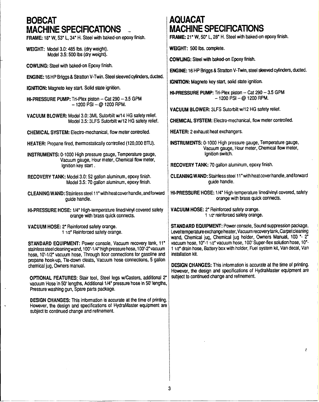
FRAME: 16” W, 5~ L, 34’ H. Steel with baked-on epoxy finish.
WEIGHT: Model 3.0:465 Ibs. (dry weight).
Model 3.5:500 Ibs (dry weight).
COWUNG: Steel with baked-on Epoxy finish.
ENGINE: 16t-fP Briggs& Sfratton V-Twin. Steel sleeved cylinders, ducte(
IGNITION: Magneto key start. Solid state ignition.
HI-PRESSURE PUMP: Tri-Plex piston -- Cat 290-- 3.5 GPM
-1200 PSI -- @ 1200 RPM.
VACUUM BLOWER: Model 3.0: 3ML Sutorbilt w/14 HG safety relief.
Model 3.5: 3LFS Sutorbilt w/12 HG safety relief.
CHEMICAL SYSTEM: Electro-mechanical, flow meter controlled.
HEATER: Propane fired, thermostatically controlled (120,000 BTU).
INSTRUMENTS: 0-1000 High pressure gauge, Temperature gauge,
Vacuum gauge, Hour meter, Chemical flow meter,
Ignition key start.
RECOVERY TANK: Model 3.0:52 gallon aluminum, epoxy finish.
Model 3.5:70 gallon aluminum, epoxy finish.
llACtIllNE SPECIFiCATIONS
‘RAME 21” W, 5(Y L, 26’ H. Steel with baked+m epoxy finish.
lfEtGHT: 500 Ibs. complete.
)OWUNG: Steel with baked-on Epoxy finish.
MINE: 16 HP Briggs & Stratton V-Twin, steel sleeved cylinders, ducted.
GNfflON: Magneto key start, solid state ignition.
II-PRESSURE PUMP: Tri-Pk?x piston--(X290 -3.5 GPM
--1200 PSI -- @ 1200 RPM.
/ACUUM BLOWER:3LFSSutorbiltw/12 HG safety relief.
2HEMICAL SYSTEM: Electro-mechanical, flow meter controlled.
4EATER: 2 exhaust heat exchangers.
NSTRUMENTS: O-1000 High pressure gauge, Temperature gauge,
Vacuum gauge, Hour meter, Chemical flow meter,
ignition switch.
3ECOVERY TANK: 70 gallon aluminum, epoxy finish.
2LEANING WAND: Stainless steel 11“with heat cover handle, and fo~ard
guide handle.
CLEANING WAND: Stainless steel 1l“withheat cover handle, andforwai
guide handle.
HI-PRESSURE HOSE: l/V High-temperature Iinedhinyl covered safe!
orange with brass quick connects.
VACUUM HOSE: 2“ Reinforced safety orange.
1/2” Reinforced safety orange.
1
STANDARD EQUIPMENT: Power consale, Vacuum recoveiy tank, 1
stainless steel cleaning wand, 100’-1/4’ high pressure hose, 100’-2”vacuu
hose, 10’-1/2” vacuum hose, Through floor connections for gasoline al
propane hook-up, Tiedown cleats, Vacuum hose connections, 5 galk
chemical jug, Cwners manual.
OPTIONAL FEATURES: Stair tool, Steel legs w/Casters, additional
vacuum Hose in 50’ lengths, Additional 11~ pressure hose in 50’ lengt
Prwsure washing gun, Spare parts package.
>
DESIGN CHANGES: This information is accurate at the time of printi
However, the design and specifications of HydraMaster equipment ~
subject to continued change and refinement.
rll-PRESSURE HOSE: 1/4’ High-temperature Iinedlvinyl covered, safety
orange with brass quick connects.
VACUUM HOSE: 2“ Reinforced safety orange.
1 M? reinforced safety orange.
STANDARD EQUIPMENT: Power console, Sound suppression package,
Level temperatureexchange heater, Vacuum recovery tank, Carpet cleani~
wand, Chemical jug, Chemical jug holder, Owners Manual, 100 ‘- 2“
vacuum hose, l(Y-1
IL? drain hose, Battery box with holder, Fuel system kit, Van decal, Van
1
installation kit.
DESIGN CHANGES: This information is accurate at the time of printing.
However, the design and specifications of HydraMaster equipment are
subject to continued change and refinement.
1/2” vacuum hose, 100’ Super-flex solution hose, 10’-
*
3
Page 6
PLIWWER’S RESPONSIBILITY
PRIOR T(3 ARRIVAL OF UNIT:
1. lrMal15N’ ~xteriorplywood flooring invehicie andcoverwi~ artificial turf.
2. Have belly mmmt~d propane tank installed on vehicle. Tank must be
propane vapor typ4 (for BobCat only).
3. Purchase heavy duty 42-6d amp hour battery arrd have battery ‘slow’
ct?argedifrww. lfhti~~isnotblty chargeddamagemfl occurfo the engine
charging mgulakw.
WADING OF QWERS MANUAL: it is the purchaser’s responsibility to
read the unit operation manual and to familiarize himself with the informs
tion contained therein. Special attention sf?ouldbe paldtoail CAUTIONS
and WARMNGS.
SALES REPRESENTATIVE’S
RESPQNW31UTY
ACCEPTANCE OF WIPMEm
f. Ifunit shows any outward signs of damage, do not sign the delivery receipt
until you have closely inspecied the unit and noted any damage on the
delivery rewipt. Have the freight company representative acknowledge the
damage by signing Me notation of damage on the delivery receipt.
2. Tim salesman from whom you purchased your unit is responsible for
Supawising tfm Wrrect installation of the unit in your vehicle and thoroughly
training you in its operation, maintenarwa and precautions.
LACENIENT OF LINIT
4VEHICLE
IERE ARE TWO RECOMMENDED UNIT PLACEMENTS:
SIDE DOOR: Most installations are side door. This provides rear
‘accessories
Mng side of machine, thus making it a bit easier to perform maintenance
!d/or repair without removing unit from the truck.
REAR DOOR: Afthough this location partly limits working access, itdoes
rect the noisa away from the cleaning site. Some cleane~ in the colder
aas prefer this location twcause it puts the weight mass over the rear
Ieels for better traction in ice and snow. Rear mounting requires+tt%?unit
b slid 10the right side as faraspossible.This not only provides adequate
inking space on the component side of the unit but al~ makes better
sight distribution inside the van (engine and component weight line up
Ier drive shaft). Also, it is physically easier to load unit into rear door due
height of van bad.
nsure that machine is well secured to the floor of van with hardware
Jpp/ied. Sudden or crash stop wili cause machine 10rocket forward, d
70 lbs. worth! Protect yourself and the maclrirw. SEC(N?E IT?
and hoses as well as unobstructed access to cornpmntf
access
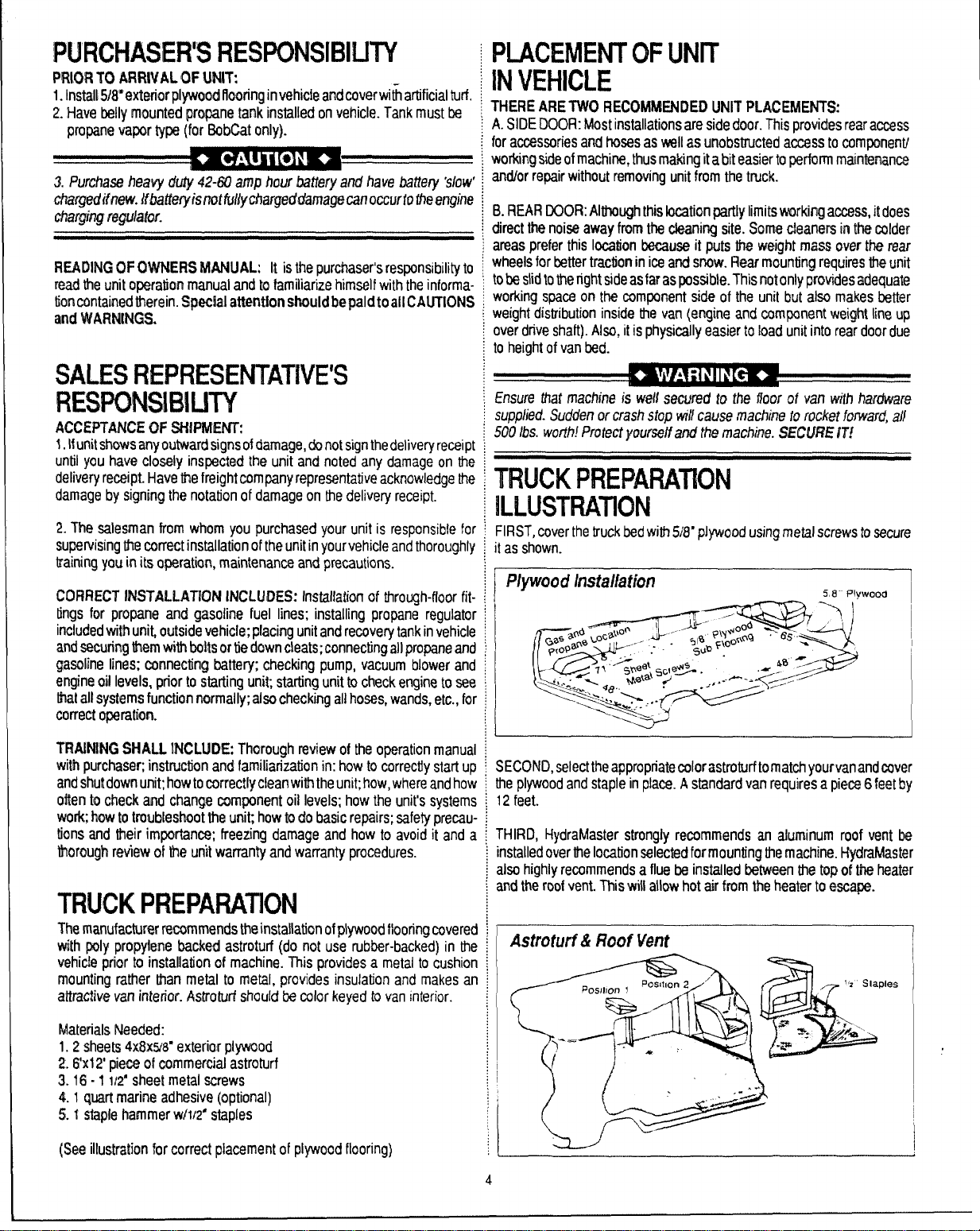
“IWCK PREPARATION
lmLWTRATION
IRST, cover the truck bed with 5/8mpJywood using metal screws to secure
as shown.
CORRECT’ INSTALLATION INCLUDES: Installation of through-floor fit-
tings for propane and gasoline fuel lines; installing propane regulator
included with unit, outside vehicle; placing unit and recovery tank in vehicle
and securing them with bolts or tie down cleats; connecting all propane and
gasoline lines; carmecting battery; checking pump, vacuum blower and
engine oil levels, prior to starting unit starting unit to check engine to see
that all systems function normally; also checking all hoses, wands, etc., for
correct opwation.
TRAINING SHALL INCLUDE: Thorough review of the operation manual
with purchawq instruction and familiarization in: how to correctly startup
and shutdown unit; how to cwrec!lyclean with the unit; how, where and how
often to check and change component oil levels; how the unit’s systems
work how to troubleshoot the unit how to do basic repairs; safety precau
lions and their imporfanoe; freezing damage and how to avoid it and a
ihorough review crl the unit warranty and warranty procedures.
TRLICK PREPARATION
Th~ manufacture recommends the installation of plywood flooring covered
with poly propylene backed astroturf (do not use rubber-backed) in the
vehiclo prior to installation of machine. This provides a metal to cushion
mOunting rather than metal to metal, provides insulation and makes an
attractive van interior. Astroturf should be color keyed to van interior.
Materials Needed:
1.2 sheets 4x8x9$* exterior plywood
2. 6x12’ piew of commwcial astroturf
3.16-1112” sheet metal screws
4.1 quart marim! adhesiv~ (optional)
5. f staple hammer w/1/2” staples
ECOhfD, select the appropriate colorastroturfto match yourvanandcover
Ie plywood and staple in place. A standard van requires a pieca 6 feet by
2 feet.
HIRD, HydraMaster strongly recommends an aluminum roof vent be
lstalled over the location selected for mounting the machine. I-fydrafdaster
Iso highly recommends a flue be installed between the tap of the heater
nd the roof vent. ~is will allow hot air from the heater to escape.
Astrowrf& Roof Venf
pies
1
(See illustration for correct placement of plywood flooring)
4
Page 7
MACHINE INSTALLATION
There are two locations to place the machine, in the side duor or in the real
door, as mentioned in the section titled “Placement of Unit.” The standara
way to configure the unit is, as shown in the illustration, with the recoveq
tank beside the unit. An alternative method, not shown, would be to put tfw
recovery tank behind the unit. (The standard machine does not come witt
enough hardware to allow for mounting of the tank behind the mactrhe. I
this configuration is chosen please contact HydraMaster for more infer
mation.)
HydraMaster recommends that the exhaust for the machine be P@
through the floor of the vehicle. It is important that the machine be placw
as cfose to the door as possible so that outside air can be pulled into tlw
engine for proper cooling.
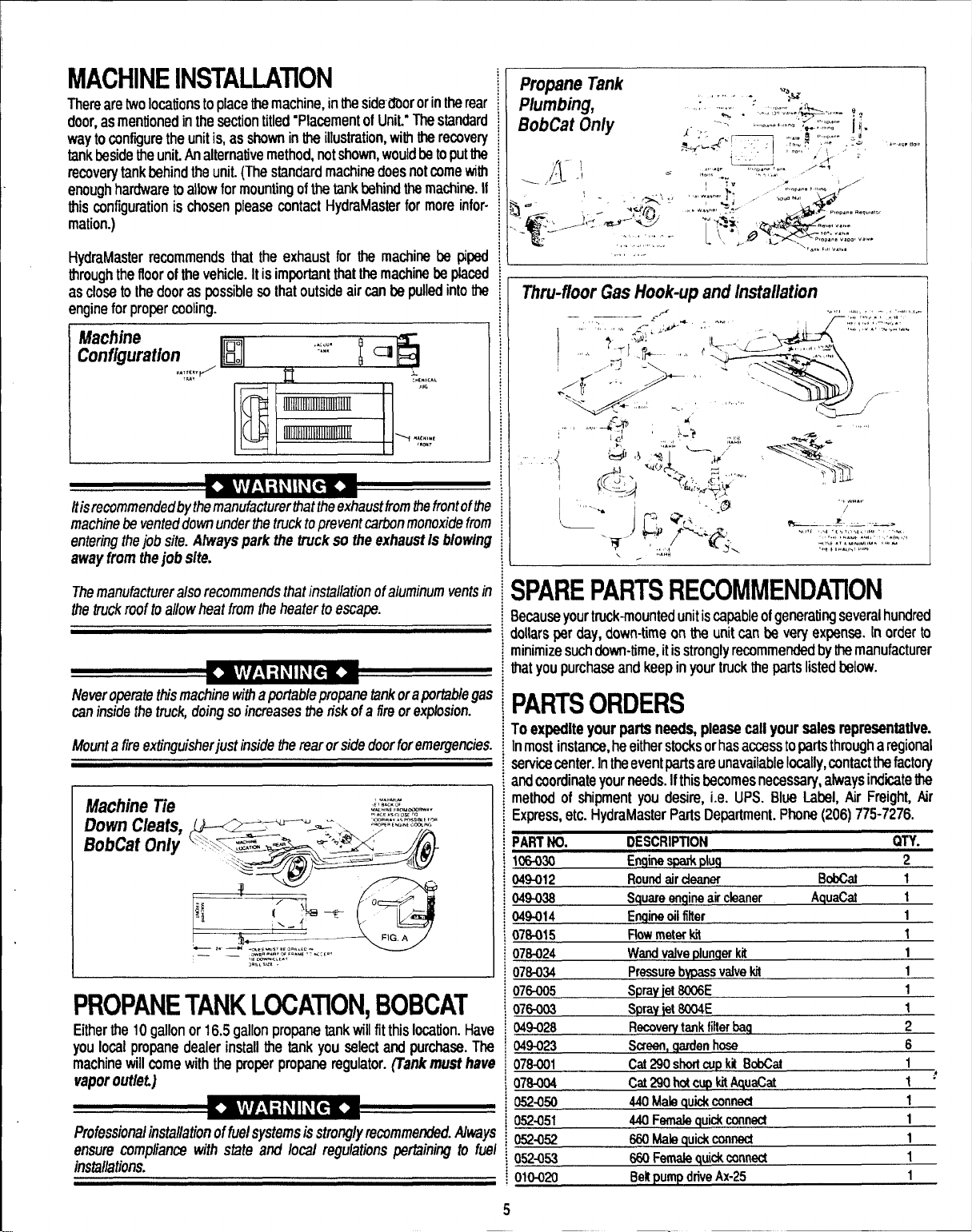
Machjne
Conflguraflon
ltisrecommendedbvthe marrufacturerthatthe exhaustkom the frontoffh
machine be vented down under the truck to prevent carbon monoxide frofi
entering lhe job site. Afways
away from the job site.
,,,,,””
,*,r’”
park the truck so the exfrauat Is &/ow/nj
Thru-iloor Gas Hook-up and h?stallafjon
The manufacturer also recommends lhat insta/iation of aluminum vents i
the truck roof to allow heat from the heater to escape.
Never operate this machine with aporlablepropane tank oraportabie ga
can inside Ihe truck, doing so increases zhe risk of a fire or expfosion.
Mount afire extinguisher just inside the rear or side door foremergencie:
Machh?e Tie
Down Cleats,
BobCat On/y
PROPANE TANK LOCAnON, BOBCAT
Either the 10 gallon or 16.5 gallon proparw tank till fit this location. Hav
you local propane dealer install the tank you select and purchase. Th
machine will come with the proper propane regulator. (Tank must
vapor outlet)
Professional installation of fuel systems is strorrglyremmmerrdad. Alwaj
ensure compliance with state and local regulations pertaining to fu
installations.
hat
SPARE PARTS RECOMMENDATION
Because your truck-mounted unit is capable of generating several hundred
dollars per day, down-time on the unit can be very expense. [n order to
minimize such down-time, it is strongly recommended by the manufacturer
that you purchase and keep in your truck the parts listed Mow.
PARTS ORDERS
To expedite your parts needs, please call your sales representative.
Inmost instance, he either stocks or has access to parts through a regional
service center. In the event parts are unavailable locally, contact the factory
and coordinate your needs. Ifthis Eecomes necessaty, always indite the
method of shipment you desire, i.e. UPS. Blue Label, Air Freight, Ar
Express, etc. HydraMaster Parts Department. Phone (206) 775-7276.
PART NO.
106-030 Ermine spark pluq
)49-012 Round air cleaner
)49036 Square emaineair cleaner
)4%014
)7s-015 Flow meter M
)7S-024 Wand
07s-034
076-005 Spray iel 6CX16E
076-003 SPraYiet 6004E
049-028
049-023
07a-ool
07s-004 Cat 290 hot CUPkitAquaCa!
052aw
052451
052-052
052453 660 Female quick conned
010-020 Belt pump drive Ax-25
DESCRIPTfON
Erwrineoil fifter
VSk3 r)iuntler kit
Preswre bvpas
Recoverv tank filler baq
%merr, mrden hcse
Cat 29o shorr
440 Male @ck conned
440 Female quick conned
W Male Quid conned
s valve M
CUP kt BobCar
BobCaI
A(auaCat
QTY.
2
1
1
1
1
1
1
1
1
2
6
1
1:
1
1
1
1
1
5
Page 8
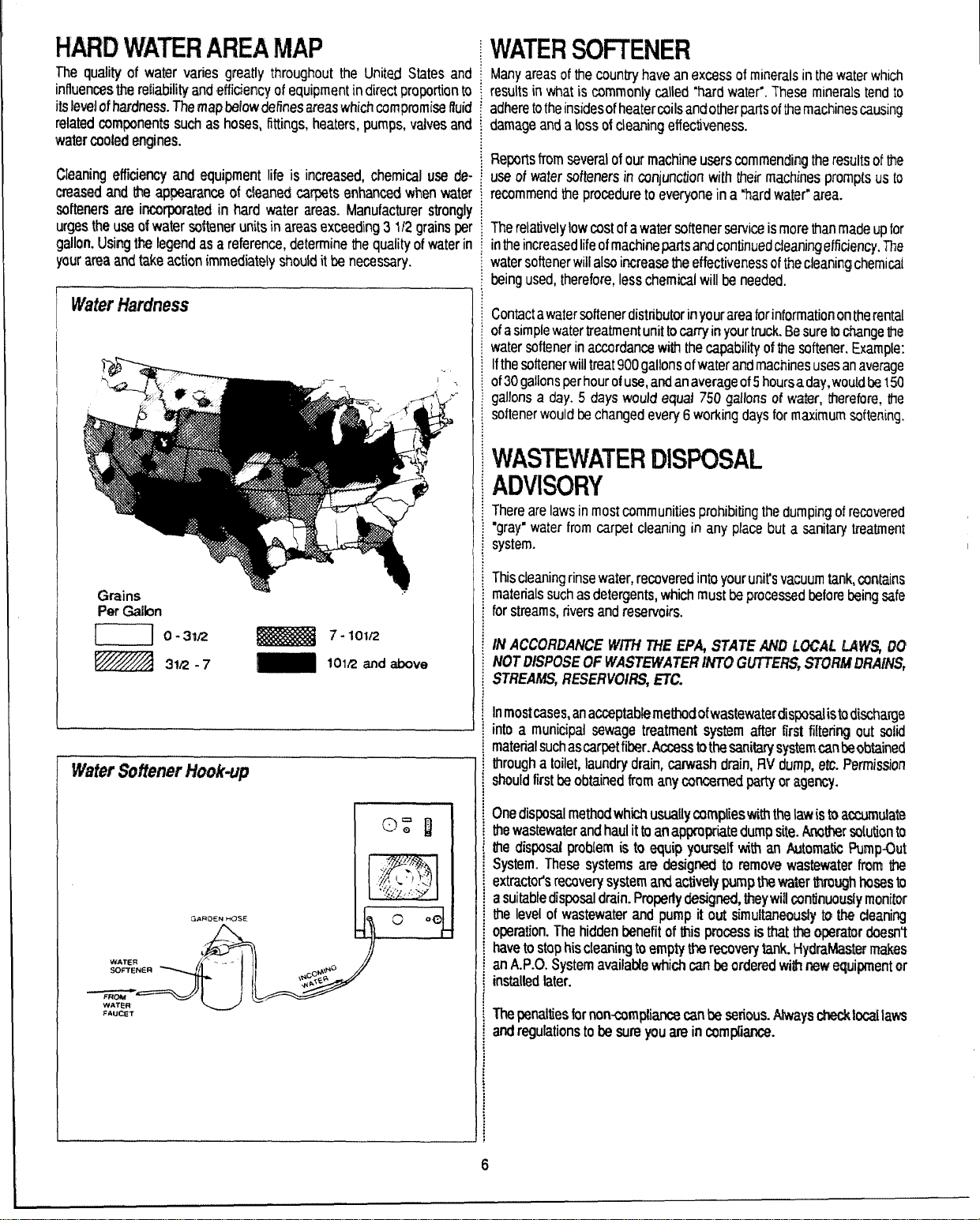
HAM) WATER AREA MAP
The quality of vvatw varies greatly throughout the United States an{
influences the reliability and efficiency of equipment in direct proportion t{
its leve~of hardness. The map bdowdefines areas which compromise flui(
related cwmfxmwms such as hoses, fittings, heaters, pumps, valves an~
water cooled engines.
Cleaning dficioncy and equipment life is increased, chemical use de
crwumd and the appearance cd cleaned carpets enhanced when wate
softeners are incaporated in hard water areas. Manufacturer strong!
urges the use of watr3r softener units in areas exceeding 3 1/2 grains pe
gallon. Using We legend as a reference, determine tie quality of water ii
your arm and tak~ action immediately should it be necessary.
INATEI?SOFTENER
dany areas of the country have an excess of minerals in the watw which
esults in what is commonly called ‘hard water”. These minerals t~nd to
idhere to the insides of heaterwils and other pans of the machines causing
!amage and a loss of cleaning effectiveness.
?e~rts from several of our machine usk+rscommending the rwx.dts of Me
Ise of water softeners in conjunction with their machines prompts us to
ecommencf the procedure to everyone in a “hard watw’” area.
~herelatively low crestof a water Wtener service is mor~ than made up for
nfhe increaw+d life of machine parts and continu@d deaningefficiemcy. The
vater softener will also increase the effectiveness of the cleaning chemical
wing used, therefore, less chemical will be needed.
;Ontact a water softener distributor in your area for information cmthe rental
]f a simple water treatment unit to carry in your truck. Be sure to change ttw
vater softener in accordance with the capability of the softener. Example:
fthe softener will treat 900 gal!ons of water and machines uses an average
}f30 gallons per hour of use, and an average of 5 hoursa day,woukf be 150
]allons a day. 5 days would equaf 750 gallons of water, therefore, the
;oftener would be changed every 6 working days for maximum softening.
WASTEVIATER IDISPOSAL
ADVISORY
rhere are laws in most communities prohibiting the dumping of recovered
‘gray” water from carpet cleaning in any place but a sanitary treatrrmt
;ystem.
Per Gdbn
W’MerSiMttM9erMwk-up
G.iROEN HOSE
&~.,
::____J=’~w
FAUCET
Wriscleaning rinse water, recovered into your unit’s vacuum tank, contains
naterials such as detergents, which must be processed txfore being safe
br streams, rivers and reservoirs.
N ACCO171?ANCE W/TH 77iE EPA STATE Al@ LOCAL LAW% IX?
NOT DiSPOSE OF WASTEWATEI? Mf7TJ GU?TKUS, STCiFfMOl?A#dS,
STREAMS, RESERVOIRS, ETC.
n mostcases, an arxx?ptablerrtrathodofwastwvaterdisposalistodwharge
nto a municipal sewage treatment system after ftrst filtering out sofii
natenal such ascar@fiber.Access @the sanitary systerncanbeobtain~d
through a toilet, laundry drain, carwash drain, flV dump, etc. Permission
]hould first be obtained from any cmcerned party or agwwy.
One disposal method whti usuatly complies witf’i the law is to accumulate
he wastewater and haul it to an appropriate dump site. Anather solution to
he disposal problem is to equip yourself with an Automatii Pump.Qut
System. These systems are designed to remove wastewater from the
Wactot% recovery system and actively pump the water Wugh hoses to
asuitable disposal drain. Properiy designed, they will continuously monitor
the level of wastewater and pump it ouf simultarwously to thre ckaaning
opmtion. The hidden benefit of fhis process is that the operator doesn’t
have to stop his cleaning to empty the recovery tank. Hydrah%tstm makes
an A.P.O. System availakle which can M ordered wifh rww equipment or
installed later.
The penalties for non-camptiance can be serious. Always ctwk$ocallaws
and regulations to h sure you are in czrmpilarrrx.
6
Page 9
START UP
1.
Perform daily/periodic maintenance as specified in tMs Owners Manual
(WW 36).
2. Connect atl required hoses.
3. Connect cleaning tool to length of hose required to perform dearring.
r~
4. Mix tankmust be ful/priortoignition.
5. Start engine (choke as required). Engine is at operating speed (recommended -2800 RPM). Allow warm-up period of 2-5 minutes.
6. Spray wand to void all air from system. When the mix tank begins a fill
cycle, the chemical flow meter may be adjusted to your desired setting.
NOTE: Chemical flow meter set at 5
is 1to 15 ratio. When flow meter is set at 10 GPH, you will be using what
most chemical manufacturers recommend at 5 GPH.
A
●
GPHisa 1 to 30 mix ratio and 10 GPH
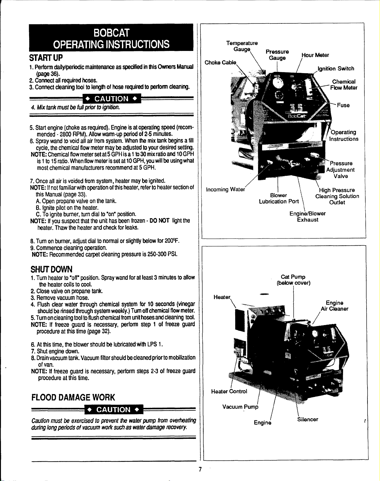
;hoke Cable.
Gauge
\ L I / ,ignition Switch
t%ssure
\
Ga~ge
Hour Meter
/
~
Chemical
~ Fbw Meter
- Fuse
7. Once all air is voided from system, heater maybe ignited.
NOTE: Ifnot familiar with operation of this heater, ~fer to healer =ction of
this Manual (page 33).
A. Open propane valve on the tank.
6. Ignite pilot on the heater.
C. To ignite burner, turn dial to “on” position.
NOTE: If you suspect that the unit has been frozen-DO NOT light the
heater. Thaw the heater and check for leaks.
8. Turn on burner, adjust dial to normal or slightly below for 200QF.
9. Commence cleaning operation.
NOTE: Recommended carpet cleaning pressure is 250-300 PSI.
SHUT DOWN
1.
Turn heater to “off’ position. Spray wand for at least 3 minutes to allow
the heater coils to cool.
2. Close valve on propane tank.
3. Remove vacuum hose.
4. Flush clear water through chemical system for 10 seconds (vinegar
should be rinsed through system weekty.) Turn off chemical flow meter.
5. Turn oncleaningtool to flush chemical from unit hosesarrd cleaning tool.
NOTE: If freeze guard is necessary, perform step 1 of freeze guard
procedure at this time (page 32).
6. At this time, the blower should be lubricated with LPS 1.
7. Shut engine down.
8. Drain vacuum tank. Vacuum filter should be cleaned prior to mobilization
of van.
NOTE: If freeze guard is necessary, perform steps 2-3 of freeze guard
procedure at this time.
incoming Water’
Heater.
Blower
Lubrication Port
‘\
Engink310wer
Cat Pump
(below, cover)
—
Exhaust
1
I
\
High Pressure
Cleaning Solution
Outlet
FLOOD DAMAGE WORK
Cauthn must be exercised to prevent the waterpump from owheatiq
dutinglongptwbds of vacuumworksuchas waterdamage recovery
Heatei
Vacuum Pump
Engine
-. .
/\
Silencer
Page 10
\
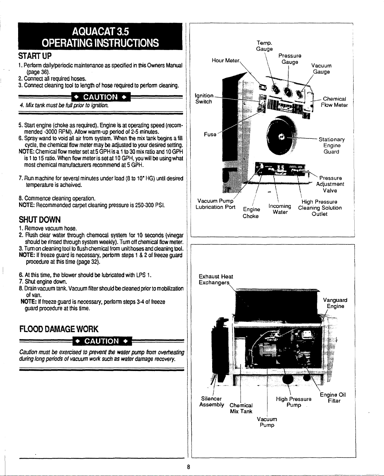
START w
1. Perform dailylp@riodic maintenance as specified in this OwrMrs Manual
(page 36].
2. Connrxt afl r~quired hosas.
3. Connect cleaning toot to I@ngti of hose required to perform cleaning.
4. Mix tank r?wttw tiilpriur to @tiort
5. Start engine (choke as required). Engine is at operating speed (recom-
mended -3000 RPM). Allow warmup period of 2-5 minutes.
6. Spray wand to void all air from system. When the mix tank begins a fill
cycle, the chemical ffow meter may k adjusted to your desired setting.
N(ITE Chemical flow meter set at 5 GPH is a 11030 mix ratio and 10 GPtl
is 1to 15 ratio. When flow meter is set at 10 GPH, you will be using what
most chemicai manufacturers recummend at 5 GPH.
Run machine for several minutes under toad (8 to 10” HG) until desired
7.
t~mperalure is acheived.
8. Commence cleaning operation.
NOTE: Recommended carpet cieaning pressure is 250-300 PSI.
Swn’DCNMN
1. Fh3move vacuum hose.
2. Flush ck?ar water through chemacal system for 10 smcmds (vinegar
should M timed through system weekly). Turnoff chemical flow meter.
3. Turmon cleaning tool to f?ush chemical from unit hosmand cleaning tool.
NOTE: If freezo guard is necessary, perform steps 1 & 2 of freeze guard
procedure at this time (page 32).
Temp.
Gauge
Hour Meter
Ignition.
Switch
Fuse
Vacuum PumD’ ~ i
Lubrication Port Eng’lne
\
Choke
\ Pressure
\
‘n~a~~g Cle;ning Solution ,
Gauge
F;.
Vacuum
w!.
II
Hiah Pressure
outlet
1
Stationary
Engine
Guard
6. At this time, the blower should be Iubrfcatecf with LPS 1.
7. Shut engine down.
& Drain vacuum tank. Vacuum filter should&e dearted prior to mobilization
d van.
fWITE: If freeze guard is necessary, perform steps 3-4 of freeze
guard procedure at this time.
FLOOD DAMAGE WORK
Caution must b exercised to prwmt thewaterpump hvn overheati~
dwirq long pfiads M
Kscwrn work suctr aswater damage recovery.
Exhaust l-feat
Exchangers,
I
Silencer
Assembly Chem&J Pump
Mix Tank
Vacuum
Pump
\
High Pressure
‘Engine CM
Filter
Page 11
MACHINE ADJUSTMENTS
Although this unit has been factory adjusted, it may require additional
adjustments to achieve optimum performance;i.e. altitude may require carb
adjustment and ambient temperatures may require heat control adjustment. When required, consult an authorized representative.
ENGINE COOLING
Units emp/o@gaircootedengin+?s must not &? enclosed w“thina van with
doors and windows closed. Excwssive temperatures within the engine will
resultinpremafure engine failure andacompromise ofappkable warranty.
LEVEL OPERATION
During operation, van or trailer must be parked on /eve/ ground noi to
exceed + or -1P. Failure to insure proper leveling may prevent proper
internal lubrication of engine, vacuum ancVor high pressure components,
FREEZE PROTECTION
Mothernafuregives/ittie wamingasto hercoldspelis. There fore, protecting
this equipment t70m freezing will save costfydown-time. Placingane/ectric
heater in the truck or parking the truck indoors, will hefp to insure against
freezing.
NO SMOKING
It is unsafe to smoke in or around the vehicle.
MOVING PARTS
Never touch any part of the machine that is in motrnn, sewn? bodily injury
may resuft.
CARBON MONOXIDE
This unit generates toxic fumes. Position the vehicie so that the fumes will
be directed AWAY from the jot) site.
DO NOT PARK where exhaust fumes can enter a building through open
doors or windows, air conditioning units or kitchen fans.
TOXIC FLUMES
Do not occupy the vehicle when tie cleaning equipment is operating. Toxic
times may accumulate inside a stationary vehicle.
WATEFUCHEMICAL FLOW OPERA~ON
HEATER
Never pile things aroundi%e heater, i.e. hoses, boxes, chemicaljugs, etc.,
as this will block the flow of air required for a clean burning heater.
OPEN FLAME
Remember that this heater is an open flame, therefore, do not remove
engine gasiine whi/e trouble shootingorstore any flammable materiaiin the
truck w“th heater operating.
STRONG PROPANE ODOR
Never light fhe heater if you smell a strong odor of propane around
the heater.
HOT SURFACES
During the operation of this equipment many surfaces on the machine will
tk?come veryhot. When near the van foranyreasoncare must be taken not
to touch any hot surface, such as heater, engine, exhaust, etc.
LIGkfTfNG HEATER
Neverputyourface down close to the opening of the heater when bghting.
I
This electro-mechanical system has been designed to be simple and
trouble free. Incoming water flows first through the Solenoid Control Valve
(I)(seeillustration on next page) andthelowpressure Chemical injector(2)
which are both mounted on the extenorof the mix tank. As the water passes
through the Chemical Injector, it is automatically proponioned with a
predetermined quantity of detergent. The Mix Tank(3) is equipped with two
different float switches, the Water Level Float (4) respmcfsto the !evel in the
tank and will maintain the proper volume of solution to be reserved for the
water pump. The secondary, Low Water Float switch (5) is a safety switch
that is designed to protect your system from sudden or unexpected loss of
water supply. If, for example, the waler source at the house were turned off,
the water level of the mix tank would drop, activating the secondary switch,
which automatically disengages the system and prevents the water pump
from running dry.
The desired chemical injection ratio may be obtained by an adjustment of
the Chemical Flow Meter (6) during flw fill cycle of the mix tank. Water must
be flowing into the mix lank inorderto adjust the chemical mix. The chemical
will flow from the Chemical Jug (7) to the Chemical F{ow Meter, then to the
Chemical Injector where it is Proportioned into the Mix Tank at the desired
chem”~l setting.
NOTE: With this unique chemical system, the chemical flow isproportioned
only during the filling cycles of the MIX Tank, not during the direct spraying
of the wand. Therefore, it is possible that as your wand is spraying, you may
have no chemical flow. Also, the converse is true in that you may not 1#
spraying your wand, but if the mix tank is in a filling cycle, your Chemical
Flow Meter may be active at the desired flow rate.
The chemical profmlioning system will mix chemical with water at a 1to 30
ratio when the Flow Meter is set at 5 GPH, or a 1 to 15 ratio when the Flow
Meter is set at 10 GPI-I.
9
(cuntilXls,mxtpage)
Page 12
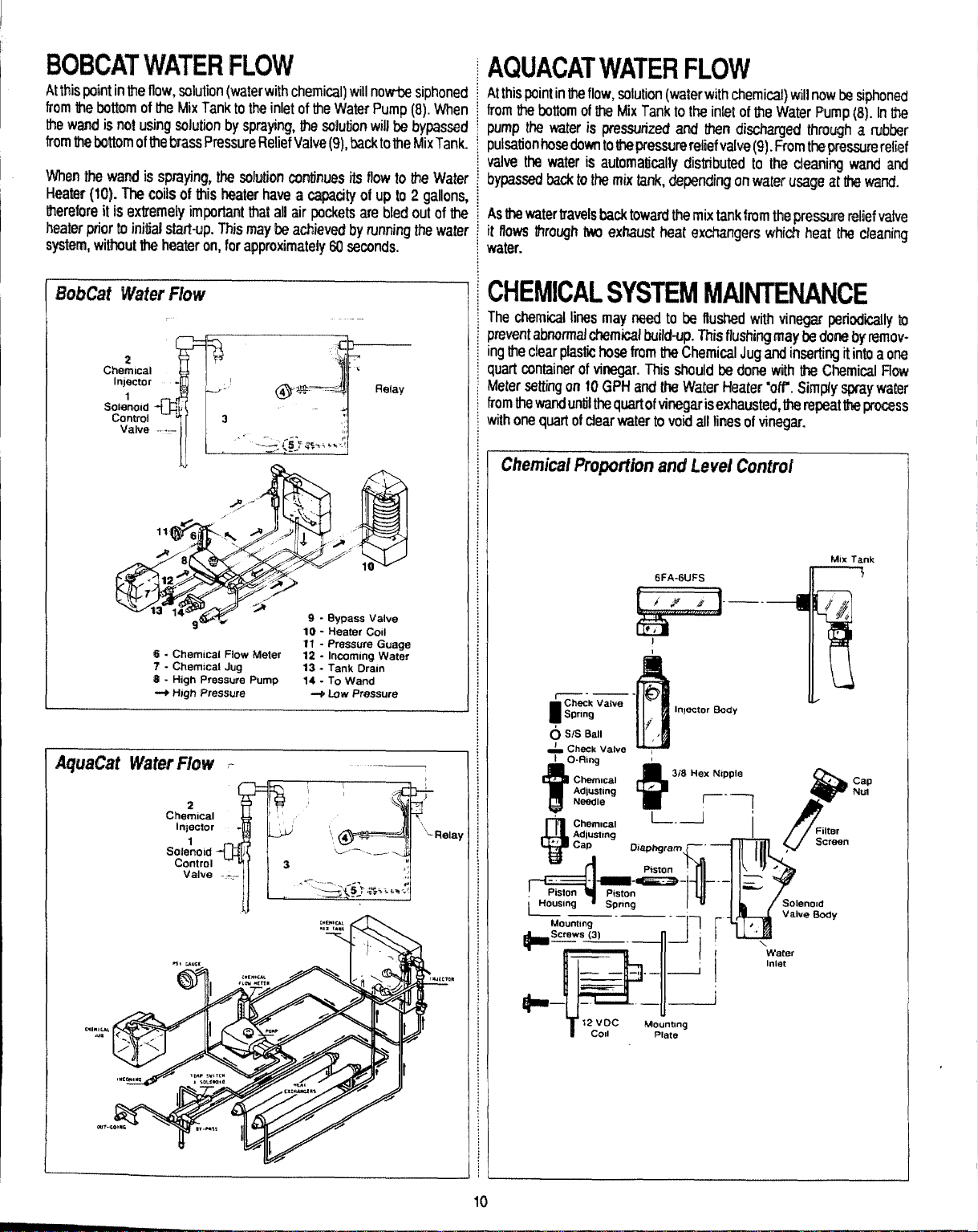
BOBCAT WATER FLOW
— .————— .-
At this paint in ttw flow, solution (water with chemical) will no’ar@ siphoned ~
from M@bcdtom of lt’m Mix Tank to W inlet of tie Water Pump (8). When ~
tfw wand is no! using salution by sprayh& the solution will be bypassed ~
from the bottom of the brass Pressure Relief Valve(9), back to the MixTank. ~
Wfwn the wand is spraying, the solution continues its flow to the Water
HtMar (10). The coils of MS twaler have a capacity of up to 2 gallons,
therefore it is extremely important that all air pockets are bled out of the
heater pricw 10 initial start-up. This maybe achieved by running the waler
systtxn, wilfwut th% heater on, for approximately 60 seconds.
Valve .-.-–
1!~ Ii
AQUACAT WATER FLOW
At this point in the flow, solution (wakw with chemicat) will now be siphorwd
from the bottom of the Mix Tank to the inlet of the Water Pump (8). In ttw
pump the water is pressurized and then discharged through a rubber
pulsation hose down to Uiepressureretief valve (9). From tfwpressure relief
valve the water is automatically distributed to the cleaning wand and
bypawd back to the mix tank, depending on water usage at tfw wand.
As the water travels back toward the mix tank from the Wessum relk?f vatve
it flows through M exhaust heat exchangers which heat the cleaning
water.
CHEMICAL SYSTEM MAINTENANCE
The chemical lines may need to be flushed with vinegar wriodiily to
prevent abnormal chemical build-up. This flushing may be dom by removingthe clear pfastic hose from the Chemical Jug and inserting it into a one
quart cmtainer of ki’wgar. This should k done with the Chemical flow
Meter setting on 10 GPH and the Water Heater ‘off’. Simply spray water
from the wand until the quart of vinegar isexhausted, the repeat W pmc$ss
with one quart of dear water to void all fines of vinegar.
Chemical Proportion i3m#Level Control
AquaCat Water Flow .
Che&lcal
ln~ac!or
SW!totd
Control
Valve
-—-—
1!
O S/S Ball
= Check
Housing
Mounting
‘—-—-–11
+Smnvs {3,
ValV13
...... , .,;;.9
——
——.,.—
1J+
*–
‘7 ‘—
12 Voc
T
Cd
6FA-6UFS
I
-0
Inpctor Body
f’
/’
(II
/w
r .
‘1
u
k40unong
Plate
!!-+(
L+i
Soleno[d
Valvo@Qdy
water
Inlet
II
MIX Tank
\
10
Page 13
CHEMICAL TANK
TROUBLE SHOOTING GUIDE -
PROBLEM Lfttfe or no chemical flow
Solution
------- .
Check that hoses at the Mix Tank(3) are secure. Check that the hose from the top
of the Flow Meter (6)10 the Chemical Injector (2) is secure with no idnks or
leaks. Check that the adjusting cap on the
atllhe way in. Check the s/s chedr valve insidethe injeciorfor chemicatbuiidup and proper cperafkm. Chac+Ithe hose from the Mtom of the flow Meter
10the Chemical Jug (7) for kinks, cmcAs, or bubbles.
Checkthescmenontheendofthehosewhichgo eaintolheChemicaJJug. Tocheck
thisscfeen for proper function, remove kfrom the plastic hose. If you cannot
blow through d,
Check the Chemical flow Meter (6)
Is incoming water pressure tees than 30 PSI?
Cracked or defective Chemkai Ftow Meter (6)?
Check the filter screen in the Solenoid Controf Vafve (l).
then rinse it out with vinegar.
for obstructions or a sticking float.
PROBLEM Inabilitv to adiust chemicai with the Flow Meter
Ilsbrii iodged behind teflon seat in Flow Meter valve.
Teflon seat on the vafve stem mav be Icase. if deteriorated. reoiace O-Rina.
insufficientwafer mssura. Locate new
side of the injector is not screwed
source.
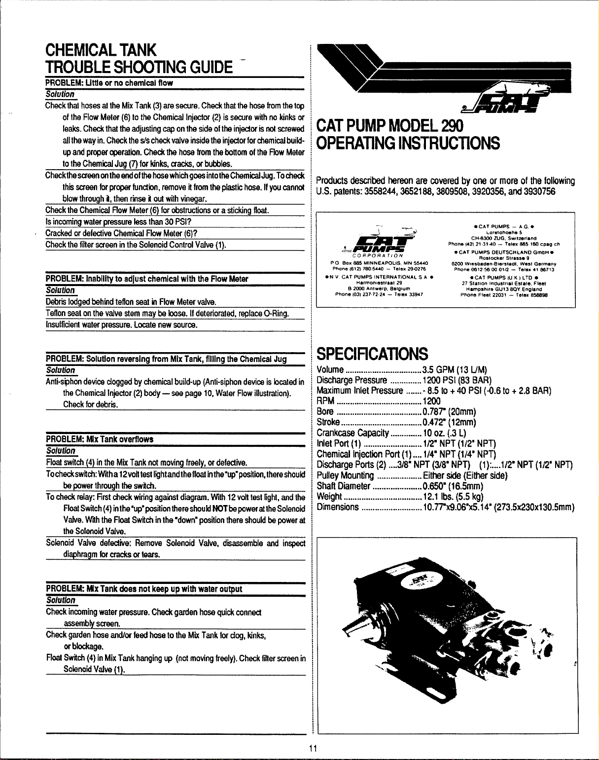
CAT PUMP MODEL 290
OPERATING iNSTRUCTIONS
Products described hereon are covered by one or more of the foiiowrtg
U.S. patents: 3558244,3652188, 3809W”, 3920358, and 3930756 -
—
Aiu#
&MM-
C017P0 RATION
PO Box S85 MINNEAPOLIS, MN 5S440
Phone 161 2) 7S0.5440 – Telex 290276
● N V CAT PUMPS tNTERNfi TIONAL S A ●
Hfmno”mstraat 29
0 261M An!vmp,
Phone 1031237.72.24 – Telex 33947
13dawm
● CAT PuMPS - A G. ●
Loretohcmhe5
CH.WOO 2uG, SwtzeNanO
21.3140- T$Jlm SS5 160 CPmO M
Plm”e (42)
PUMPS DEUTSCHLAND GmLIHG
● cAT
Roe.! ocker Strms. 9
8200 Wlesbaaen.fllamtadt, West Germany
PhO”e C812560001i2 — Tela, 41 @S713
● CAT PUMPS (U K ) LTO ●
27 Stat(O” +“dustrlal Estate. Fleet
l+arnPshl<eGU13 6QY England
Pho”eI F!mt 22031 — Totem 65SSSS
PROBLEM: Soiutfon reversing from Mix Tank, fflling the Chemicai Jug
Solution
Anti-siphondevics dogged by chemicai buiid-up (Anti-siphon device is bcated in
the Chemical Injector (2) body — seepage 10, Water Fiow illustration).
Check for debrii.
PROBLEW. MIx Tank overflows
Solution
Fioat swifdr (4) in the Mix Tank not moving freeiy, or defedive.
Tochackswifch Wrha 12voiftast iightandtheffoat inthe”up”positiirr, thereshoukf
be oower throuoh the swkfr.
To check raiay First“deck wiring against diagram. Wtih 12 volt test light, and the
FioafSwifch (4) inthe’up”position there should NOT bepowerattheSoienoid
Valve. Wtih the Fioat Switch inthe “down”positian there should be power at
the Sofenoid Valve.
Solenoid Veive defedive Remove Soienoid Valve, d~assembie and inspect
diaphragm forcracks or tears.
PR08LEkk Mix Tank does not keep up with water output
Soiution
Check irmming water pressure. Check garden hose quick connect
assembly screen.
Check garden hose ardor feed hose to the Mix Tank for dog, kinks,
or bfockage.
Float Switch (4) in Mix Tank hanging up (not moving freely). Check fitterscreen in
Solenoid Wdve (l).
SPECIFICATIONS
oiume
..................................3.5 GPM (13 lfM)
ischarge Pressure
i~imum iniet Pressure .......-
PM ......................................1200
ore ......................................0.787 (20mm)
troke
....................................0.472 (12mm)
rankcase Capacity .............. 10 oz. (.3 L)
liet Port(1) ..........................
heroical Injectiin Port (1).... 1/4” NPT (l/# NPT)
ischarge Ports(2) ....3hY NPT (3/8’ NPT) (1 ):....1/? NPT (1/2’ NPT
uiiey Mounting
halt Diameter
/eiaht ...................................12.1 ibs. (5.5 ka)
lim%ions ...........................10.77W9~O&x51{# (273.5x230x130.5mm)
..............1200 Psi (83 BAR)
8.5 to+ 40 PSI (-0.6 tO + 2.8 BAR)
1/2’ NPT (1/2’ NPT)
.................... Either side (Either side)
...................... O.6!W (16.5mm)
11
Page 14

GENERAL INFORMATION FOl?
CAT lWMp IWIW? -
As you rwnove your dischargra manifold, there is a set of 3 check valves
(which usually fall out during dismantling]. If the sudaces of the%e check
valves am dirty, or show signs of chemical build-up, it is probable that they
would rwnainopen causing pressur~ loss orpu!sation. Upon inqwcting the
valves, make sure that the tef!on button in the valve spring retainers are still
intact. Also t?xarnine the discharge manifold. Look for problems such as
cracks, chwnical buildup or warping due ta freezing. If this discharge
manifold is warp@d, it will cauwl the check valves to stick and will result in
[0ss of pressure.
The Cat pump cups are often the source of pressure loss. I@m inspection
they may appear melted or torn, but often they will look good. Replam them
anyway. There isno sur’ernethodofvisual lyinspecting the cups. HydraMaster recommends changing cups whether they look good or not.
SERVICING THE PUMPING SECTION
IISMANTUNG
1.Remov@ discharge manifoti as described in the last ser%on.
L Slip cylinders out of inlet manifold. N(2TE: Identify cylinders so they will
be repiaced in their original position (front to back).
1.Remove cotterpm, nu~ and washer.
L Next remove piston retainer, spacer, and ptston as~mbly.
i Remove inlet valve
WEASSEMBLY
1.Examine inlet valve surface and reverse if damaged (both sides are lap
surfaces).
L Examine piston assembly for clean inlet surface. Ifdamaged, replace and
lubricate.
UOTECUPINSTALLATiON: Wipe cup inserter Iightiywtth od. Slip batxup
ring onto piston. Force cup over inserter and square with al surfaces.
Faulty cup installation causes premature failure.
Anytime your pump is being dismantled, HydraMaster recommends replacem~nt of all ‘o’ rings and saals. This is mereiy a convenience to the
customer to make sure that the Cat pump is in top operating condition.
The Prm-A-Lube seafs located within the intake manifold will allow air to
@nter fhe pump if they are worn. Again, it is difficult to visually pinpoint a
dilft?ctfve Prrmrn-A-Lube seai. Replace them all.
Repairing of Cat pumps is not a difficuh task.
make sure you have the profwr parts required.
1- short (or hot) cut kit
3- Wrmrn-A-Lube seals
Read instructions thoroughly, supplied in the Cat pump manual prior to
dismantling and follow directions as stated. Oil all seals thoroughly prior to
installation. (Remember, a newly scarred seal isno better than one you just
took out.)
6- piston sleeve ‘o’ rings
1- txlt?fe Cat oil
However, before dismantling
SERVICING DISCHARGE VALVES
a VALVE SEATS
DISMANTLING
1. Loosen ttm 2 (M8) locking nuts approxirnataly one turn.
2. Then remove the 2 (M8) flange nuts.
3. Graspthedischarge manifoldwi~3tingerson the underside andtapwith
a sdt mallet to remove.
4. Valve as~mblies will remain with the manifold. Invert manifold and
discharge valve assemblies should fall out.
5. Inspectdischarge vaivesforwwarorridges. (Spherical valves due to their
shape must be replaced when worn.)
REASSEMBLY
1. Place rwtainer in manifold chamber.
2. Next insert spring intD center of retainer.
Macevalve over spring with spherical (mooned) side up.
3.
4. M3xt inswt the valve wdat.
5. Position manifold back onto pump.
MOTE Exrwckm caution Men inserting cylinders into manifold to avoid
damaging cylinder o-rings.
6. Replaca fkmge nu!s on studs and hand tighten both sides. Then torque
each side to 125 inch paunds.
7. Hand tigh!en locking nut.
When re.starfirg tie pump, check fo .%Mthat there Lsno cylihdermofiona$
this will cause flremahxe failure of the cvlirmfer o-firm. Center ctiincfe~
mtkm cm be &imtha?ed by SwiMing wi~hor?eof the-endcy~inde;s.
1 Next replace piston spacw and retainer.
$. Slip washer onto rod, screw on nut and torque to 60 inch pounds.
NOTE AL WAYS REPLACE WITH MEW CCWTE6?PN
j. Examine cylinder wails for scoring or etching. These ccmditions will causa
premature wear of your piston assemblies. Replace ifworn ordamag@d.
5. Lubricate cylinder and replace o-rings and backup rings (if defective).
7. Position cylinders in their original order into manifold chambers and
carefully slip over rod ends onto the pump.
3. Replace flange nuts on studs and hand tighten both sides. Then torque
each side to 125 inch pounds.
9. Hand tighten locking nuts.
SERVICING THE SEALS AND SLEEVES
DISMANTUNG
1. Remove discharge manifold and piston assemblies as described.
2. Remove fxIth (M8) locking nuts from studs.
3. With soft mallet, tap inlet manifold loose from crankcasa
4. Place inlet manifold onpairof clearance blocks with crankcase side down
and drive out seals.
5. Invert inlet manifold with CRANKCASE SUE UP.
&Lubricate circumference of new Prrrrrm-A-Lube seats, position inrnanifold
with GARTER SPR/AfG i)UWPJ and drive into place.
7. Examine sfeevw for scoring or other damage before removfng.
3. Ifworn, grasp sfeeve with pliers and pull off.
NOTE This procedure will mar the sleeve SQuse onfy if sleeve is
to be replaced.
9. t7emove o-ring and back-up rings from piston rod.
REASSEMBLY
1. Placa barrier slinger on rod.
2. Lubricate new o-rings and back-up rings. Install first o-ring in the o-ring
groove on the piston rod. Position back-up ring against the shoulder
front of the first o-ring, then the secxmcf o-ring. Be careful to awoid
damaging the o-rings when Qipping them over the piston rod
threaded ends.
3. Immerse sleeve in oil carefully lwist and pushonto rod (machim?d counter
bora eti first).
4. Repface seal retainers.
5. ExerciW caution wmn replacing inlet manifold, w the inlet seals are not
damaged by the fhreaded rod ends.
6. Replace Iockhg nuts on studs.
7. Reassemble piston assemblies and discharge manifold as described.
Consult factory for your loud distritwtor for crankcase servidrrg.
in
12
Page 15

DISMANTLING CAT PUMP
Pumping Sect~on Cut-away
P!ston Spacer
Bat-cup
/
Bee-Cup Rmg
‘“t”-“ROds’eeve
;ERVICE KITS
78-001 Cup Kit BobCat
cup
O-Ring, Cylinder
COtterpin
Instruction Sheet
Cup Inserter
Hot Cup Kitj AquaCat
7S404
cup
0-Ring, Cylinder
Cotlerpin
InstructionSheet
Cup Inserter
78-003 Seal Kit
Prrrrm-A-Lube S&d
Cotterpin
Abrssive Paper
Instrudion Shed
0431 Sleeve
IPrrnm-A-Lube Seal
BarrierSlinger
I
I Colterpin
ISleeve
iO-Ring, Sleeve
Instruction Sheat
and Saal Klt
Cyhnder
,7
/
30666 Valve
3 Valve Spring Retainer
3 Valve Spring
3 Valve
3 Valve Seat
3 O-Ring, Cylinder
1 Instruction Sheet
30660 Piston Kit BobCat
6 0-Ring, Cyiinder
3 Back-Up Ring, Cylinder
3 Bat-Cup Piston
3 Bat-Cup Ring
3 cup
3 Piston Spacer
3 Piston Reltiner
3 Conical
3 Nut (M6)
3 COlterpin
3 Inlet Valves
1 Instrudion Sheet
Kit
Washer (M6)
a
.d
13
Page 16

PISTON Mcmil 290 Explod@ View _
PARTS LIST MODEL 290
ITEM
10
11
12
15
PART NO.
1
2Q285
2 44274
3 1!%-OOa
4
097-004 O-Ring, 01 fi~l~ ~
5
027-007
843340 O-Fiing, mankcase cover
9
43-324 Crenkcas.e rover
074-021 Wkbte oilgaug+3
23170
25625
92520 Sem$ comb head screw (M6 x 20) 6
m 43fw4
17 144a7
la
19
20
21
23
25 1’6948
26
27 147406
2a
29
Wm Back-up riig, Sleeve {Teffon)
31
32 26864
32
34
35 147-008
35 30325
1
A7JWW
!-r, w“” Oil ad @ma-N)
097-007
041-021
19
9251
3n1709
.“. .-”
W180Q
2#?7
25327
097-008
2a771
29614
1%-001 SW retainer
25na
25S35
DESCRIPTION
O-Ring (Buns-hl)
Crankcase
Stud (M8
oil fillfwI-s 1
O-Ring, drab plug
X 62)
. ......
--r
l%ain plug
Crarlkshafl 1
Rearino 7
O’l?irlg, Oifseal case
al s{
WI case
Sems comb head screw (M6 x 16] 8
Cannedng md
Piiton KM 3
PEttm pin
Seal washer
oil Snd 3
Wnier sfingef
Wing,
sleeve
Ming, sle9ve (Won)
Sleeve (%4743 Unchmwd)
Seal washer
Met
manifold
Met manifold - stainless steel
hrrm-A-Lu& seal
Prmrrm-A-Lube seal (Won)
QTY.
1
1
2
f
1
1
1
1
f
22
2
3
3
3
3
3
3
3
3
3
3
1
1
3
3
ITEM
36
39
40
41 044-ool
39-41
39-41
42
43
44
45
46
47 045-004
46
49
500WO05
51 43442 Vatve spring r~tainer
5243360 Valve spring
53 43723 Valve
5443434 tlk.charge valve seal
56
57
58 108-OO3 Shafl pramctor
PART NO. DESCRIPTICIN
27004
30543 Bat-Cup piston
097425 I&Cup ring (Tefkm]
43474
001
0784
004 AauaCat
0784
33 PiitonSOacw 3
2796
27002
27066 Oomicalwasher -s& (M6]
27000
14158
097-012
11377
097424
Inlet vaJve
cup (Won)
Bac-(hm assamblv 3
M&t Cuokii
Clla kti t
Piiton retainep
S/S (M6)
Nut C@erpin
cylinder (434334Unch]
O-Rhg, cyiinder (WM-N]
O-Ring, cyfinder (Won)
Bao-Cup
ring, cyfindw
Discharge
25634 Di*ge manifold - sls
81109 Hex nut (MB)
101604 Hex flange nut (M8)
EIactrfc Clutch AesembW
59 152-005 “ Tapered sl~ve
60
61
62
63
64
077-005
036-005
143-084
174-004
174-018 f-cd washw (5/16 US) 1
Key, Wcfric clutch
6“ elec$ncclutch
8-30 mm sacket head sww
Ret wash~ (5/tLI US}
manifold
my.
3
3
3
3
3
3
3
3
3
6
6
3
1
1
3
3
3
3
2
2
1
1
f
1
1
1
14
Page 17

CAT PUMP TROUBLE SHOOTING GUIDE
PROBLEM Pulsation
cause So{utforr
Dabrii in discharge valves of pump.
Worn Prrrrrm-A-Lube seats.
Exrxssive temperature.
PROBLEM: Low pressure
cause Soluffon
Worn nozzle, Re+kca nozzle of proper size.
Belt sfippage.
Air leak in inlet plumbing.
Relief vafve stuck, partiafly plugged or improperly adjustad; vafve seat worn.
Infaf suction strainer dogged or improper size.
Worn piston assembly. Abrasives inpumped fluidor serve cavitation. Inadequate Instaflpraperfifter. Sudion at inletmanifoldmust be fimifedfofiffing less than 20 feet
water suf@y.
Fouled or dirty inlet or discharge vafves.
Leaky dscharge hose. Rapfaca worn valves, vafve seats.
PROBLEM: Pump runs extremefy rough, pressure is very low
cause
Restricted inlet or air entering the
Infet restridions arrd/orair leaks. Damaged cup or stuck inlet or discharge vafve.
Worn inlet manifold seats. Prrrrrm-A-Lubes. Replace worn seek.
inlet plumbing. Proper size inlel plumbing; check forairtight seal.
Ctean or replaca discharge valves.
Replace.
Check pump sofenod.
Tighten or r~lace; use corrad heft.
Dismantle, reseaf, and reassemble.
Clean and adjust refief valve; check for worn and diriy valve seats. Kitavailable.
Clean. Use adequate size. Check more frequently.
of water or -8.5 PSI vacwm.
Clean infetand discharge vafve assemblies.
Replace discharge hose.
Solution
Replace worn cup or cups, dean out foreign material, replace worn vafves.
PROBLEM: cylinder O.Rings blown next to dischsrge manifofd
Cause
Pressures
Warped manifold. Freezing.
PROBLEM: Leskage at the cyflnder O-Rkrgs st the discharge manifold snd
inexcess of rated PSI.
bfack, powdery substance fn the area of the O-Ring
cause
Loose cyfinders. Cylinder motion caused by improper torque on the &charge Retighten, Donottightentoomud ortheeiwsof the manifoldwiilbebwed,causing
manifold.
PROBLEM: Water Ieakaae from under the infet manifold
cause
-et manifofdseals.Prrmm-A-Lube.LeakingsfeeveO-Ring.
PROBLEM: Oil leak between crankcase and pumplrtg section
cause
Worn crankcase piston rod seats.
PROBLEW Off leaking In tha area of the crankshaft
cause
Worn cmkshaft seat or imprcpa rfy ins!aflad oil seal.
Bad b+mring.
Solution
Check forplugged nozzle, dosad vafves or imprcp
Replace marrilofd.
so/uffon
fooseness in the canter cylinder.
Solution
Installseats.
Ifpiston rod sleeves are scared, rapfaca sleeves and sleeve O-Rings.
Solution
Replace crankcase piston rod seafs,
Solution
Remove oifseat retainer and reptace damaged gas
Replace bearing.
rfyadjusted bypass vafve.
ket andhr seats.
rmnknws. next me)
(
15
Page 18

CAT Pwiwmowx wmrw GUIDE
PROBLEM Excasslva play In the rmd of Ma crankshaft puilwy
CalIsa
ITXiGil bearing tmmnexrxrs.sivetension on drive belt.
Solution
Replace ball bswing. Prcprty twrsion belt.
PHtXM.Efk
Cause
=causad by humid tir mrrdensirq interwater insido Ihe wankcase.
Linkage of maniiold inlet seafs andlor piston rod sieaves O-Ring.
PRcIEILEiW Oil leaking from undsrsida of crankcase
Cause
Worn crankcase piston rod seals.
PRQfM,.Ehk Oli ieaking
Cause Solution
-d or improperly irwXaJiedoii gauge orcrankcase rear cover O-Ring, and
Water In crankcase
Solution
Change oil at 3
approved oiievery month or 200 hours).
Replace seals, sleeves and O-flings.
Soiution
Rapiace seals, sleeve and O-flings.
at the roar portion of the crankcase
Repiaw oii gauge or cover O-Ring, and drain
drain duo O-f?irm.
WWWfk.Eh%Oil Ioakage from drain piug
Cause
=rain piug or worn drtin pfug O-Ring.
PHCIHLEhk Loud knockirtg noise in pump
Solution
dram piug or repiace O-Ring.
Tighten
cause Solution
Pulfey Ioase on mrrkshatt.
fMoken worn baring, Replace lmrirrgs.
Check key and tighten set screw.
manth m 500 hour intervals usinq Cat pump cmrittraw oil (othw
plug O%ing.
fWOHLEM Frequent or premature
Cause
Smred r9ds
CIWMpressure to inlet manifold.
or sieews.
faiiweof the inlet manifold aeais
Solution
Replace rods and sleeves.
Reduce iniel pressure ~
Cau$$ Sohrtion
Abrasive matisriai in the fluid king pumped.
Excessive pressure andfor temWrature of fluid being pumped.
pressure of pumps. Rs&rw pressure.
Over
Running pump dry.
Front edge of piston sharp. flqhce with new pkton.
WN3HLEht SVongt surging at the iniet and iowpt’esaura
Cause So!ution
Foreignparticles intheiniet ordischarge vaJveorwom inletmd/wtiwhwgevdves.
on thedischargeside
Irrstatlproper filtration onpump inlet pfurnbing.
Check pressuresandffuid intettemperamre;be suretheyarewithii s@ftirangw
Ca not runpump withoutwater.
Check forsmooth lap surfaces on irrle4and discharge valwe saats. Diw%arge valve
seals, and iniet valve ssata may be iapped on a vwy fine oilstone; darnag@d :
cups and disc+wge valves cannot be !appsd but muet b replac.ad.
16
inslruc$ions.
Page 19

HIGH PRESSURE PUMP
TROUBLE SHOOTING GUIDE -
PROBLEM: Loss of pressure
Cause/Solution
-- —.. . ..— .
1. Clogged fitter screen in garden hose quick conned coupler.
A. Remove and clean or replace fiker.
2, Low waler pressure at source.
A. Determine rate 01 flow and select an alternative source of supply if water
pressure is inadequate.
3. Defective or blocked check valves inhigh pressure pump cylinder head.
A. Dsmantle cyfinder head and replace or c!ean applicable check valve.
4. Delaminated, kinked or dogged hose betw~n the mix
pressure pump,
tank and the high
I
~BYPASS PARTS UST
7
Q?
8
5. Defedivepressure refiefvalve ordabris inpressure reliefvalve. NOTE The high
pressure bWass valve is desgnad to fully dose when the cleaning tool is
turnedon. Any foregn matter colleding on the pistonwill prevent full cbsure
ofthe valve and allow a portion of the water to continue 10circulate instead of
being routed to the cfaaning tool. To correct !his situation, the bypass valve
must be dsmantled and deanad (refer to illustration provided for bypass
dismantling),
A. Dismantle and clean pressure relief valve as shown in illustration.
ELReplace defedive or worn out bypass cup.
C. Replace bypass valve.
6. Defective or worn cups.
A, Remove and replace piston cups as defined by pump section of this manual.
7. Loose drive bait for high pressure pump.
A. Readjust baft as required or raplaca if defective.
PROBLEM Irtsufffclent or excessive water flow
Ceuse/So/ution
1. Wornout sprayjet. NOTE: Cleaning toois desgned to spray a constant flow of 1
IL? GPM willaverage 1 gation of flow par minute in aduai working situations
since flow isnot continuous. An average flowof 1GPM resultsin6000 gallons
of fbw for every 100 hours of unit operation. Spray tips are capabie of
consistent flow rates for approximately 20,000 gafions. They should be
replaced therefore approximately every 3541hours. Worn spray jets ailow a
greater average rate of flow thus reduang desired temperature Ieveis.
A. Remove and repfaca sprayjet.
~ REF. NO. PART NO.
OOO-105-1OI
3
4 NJO-105-1O2 Piston date. Bypass valve
cOo-076-lol
5
7 000-146-004
Q nrllr?n7.MK n 0:. ” n,-..
~ - —v-~-.J
DESCRIPTfON
Thmst plate, Bypass valve
.-.-. ~.-.–,—
seal for By
Kit,
Seat & O-Ring
-nllly, Uywss valve fitting
AquaCat Water Fjow
~..
Chekcal
Iniector
Sol~noid
Control
_
Valve
QTY.
pass valve
I, Bypass valve 1
...—
I
,,,
,(,,
,,::
1
1
1
1
2. Reductkm of flow.
A. Due to increased iengfh of solution hose. NOTE For every 50 feet of hose
beyond 100 feet intotal length, a measurable iossof flowis experienced. This
condition is a
passas through the hose. Therefore, itis necessary to increase the pressure
at ihe machine 40 PSi for every additional 50 feet of cleaning solution hose
over 100 feet.
resultof the increased frictionexperienced by the water as it
17
Page 20

WIFORMATICN
Ttm vacuum blowor irmorporated in tiki machine is a positive displatx?ment lobe type, manufacttmd by Coqwr Industries. Tle performance and
Iifa of this unit is gfieatiy dependent on tha care and pro~r maintwwrwe
it receives.
. . . . ... --—. .--. —-- ———— -—-.
‘ACUUM TANK FIL~Ell 5AC3S
/draMaster filter bags are designed to traQ all of tho lint, that would
rrnaily colleot at the tmttom of your vacuum tank. Tlm use of these bags,
wnptied at the end of each job, till elirninab? tfw budd-up of muoh of 8W
;Ms in the tank. The drawstring top of these bags is designed to be tiwl
the incoming dirty water inlet in the vacuum tank.
Jreotder bags use part number 049-028.
Hecausa of the clowa talwances between Me lobes and housing of the
vacuum Mower, solid objects entering the ink?t will damage the internal
lobes, gears and bearing or direct drive caupler.
To prevent this, a stainless steel filter screen has keen placed at he
vacuum inlet insido the vacuum recovery tank. This stainless steel screen
is finger tight and should be removed for cleaning weekly.
When machine is being nm tar test purposes and the vacuum in~ef on top
of machine ix iJp@n,cautr’oi? should be used.
To prot(?ct the vacuum blower from overloading and damaging itself, there
is a vacuum retief system installed on the vac tank. When the vacuum tank
inliilt is completely sealed off, a maximum of 12 HG will I-Eattained. A hole
on the top blower pipe elbawacts as the lubrication point. At the end of each
day, LR31 or Pennzguard should be sprayed in before shutting down the
machine. See blower lubrication illustration. If you fail to lubricate the
vacuum blower daily, rust depusits and moisture will decrease the life of
the vacuum blower.
Read the vacuum blower manual carefuilyfor proper oilchange andgreasa
application. The maintenance log may differ slightly from the manual, but
the buck-mounted carpet c!eaning machine application is very demanding
of Uaevacuum blower and therefore it should k maintained more regulatfy.
Vacuum Tank FNimI Bags
HOSE
C>FC
f310wer Lube PM
V?.CUUM
“0s E
NOTE: Vacuum tank isprotectt?dfnxn avefllowingbya vacuum tank, flea
MI switch. This switch is not activated by foam, only by liquid.
vacuum Fi(?w
S/S Filterk
Blower
Exhaust
Silencer
Recovery Tank
. Engine
Filter Bag
/
Exhaust
c)
I
Spray Iubriit into blower IUIN port for 3 to 5 seconds,
then immediately shut off machine. Use only LPS 1
moisture displacing Iuiwioant.
I
18
Page 21

VACUUM BLOWER TROUBLE SHOOTING GUIDE
PROBLEM Loss of pressure
Cause
-d vacuum hose between bbwer and
vaczrumtank.
Clogged stainless steel timer.
Defective
Defaciive or “open’ vacuum tank dump valve.
vacuum tank seat,
Fractured weld on vacuum tank.
Collapsed or kinked vacuum hose.
Plugged vacuum hose.
Restriction in
Worn end plates or Ides
cfeaning tool,
in vacuum blower.
Defective relief vafve.
PR06LEW. Blower is seized
Cause
Rust.
Foreignmatter.
77reatrovementioned, rust, rbreign matterandseizingare often causedrhrn
Note:
foam traveling through theblower.
Soiutfon
I%rnove and replace hose.
for repfacem
Remove and dean w repke stakdess steal filter.
I%mova and rsplaca
Cbsa valve.
Repfaca valve.
Rwekf as required or rapface tank.
Rash
apahosaifpass
Remove obstructionsby reversing tfw vacuum hose.
Remove obstmction.
Replace worncomponents.
Inspect and replace ifnecessary.
Solution
Spray rust dissolving lubricant onto lobes to emulsify rust and attempt to rotate
vacuumlobes.
Dismantle and remove foreign matter and repair as required. NOTE: Dismantling
must be accompfishad by qualified taohnican.
NOTE A qwial reinfomd hose is r@md
ant.
vacuum tank seal.
We andhr eliminate kinks.
NOTE Mustbeaccompfishedbyaquafifiidtechnican.
PROBLEM Noise in vacuum blower
Cause
ViRijears.
Lack of lubrication. NOTE: Permanent damage may have resuftad from lack
solution
Remove and replace gears. NOTE: Replacement of gears must be acmmplisfwd
by quafifii technican.
Timing of vacuum blower has been changed due to worn components. NOTE
Replacement ofcmmporrentsmust be amompfishad by quafiied tachrr”ban.
Lubriieas specifiedbyapplicabiavacuum blowermanuaf. SaeTabla ofConlanls.
of lubrication.
Worn be~”ngs.
Debrii and/or foreign material build-up.
vacuum inlet located in vacuum blower components. k accomplished by qualifii tachnican only. Replacement of worn parts is
NOTE A stainless stael filter isprovided in
Remove and
Dismantle vacuum bbwerand remove foreign materiil.
replace trwings as required. NOTE: Must be accomplished by
quaMiad technican.
NOTE Dismantling should
necessary.
Tighten
Loose or missing mounting bofts.
or reinstall mounting bolts.
19
Page 22

VACUUM BLOWER WARRAtW’Y
FULLER warrants products of its manufacture to h free from defects in matf?riil and workmanship if properly installed, maintained, and oporated
undw normal cwrditions with competent supervision.
No lx!rsan,
in ccmrmction with any of FLILLEF3’S products.
This wmranty sha~i extend for two (2) years from date of installation provided this equipment has been put into sm’vice within six morMhs aftw
shipment from tie FULLER factory. If repairs or replacements are made by the Purchaser without FULLER’S prior written consent, FULLER’S
warranty shali cease to he in effect. No allowance wili be granted for any repairs or alterations made by the Purchaser without FULLER’s@rwritten
consent.
Machinery, equipment and accessmies furnished by FULLER, but manufactured by others, are warmrted only to the extent of the original
manufacturer’s warranty to FULLER.
FULLER agrees at its option to repair at th~ paint of shipment or to replace without charge f.o.b. point of shipment, any part or parts of pmdwts
of FULLER’S manufacture, which within the specified warranty period shall be proved to FULLER% satisfaction to have @en defectiw when
shipped, provided the Purchaser promptly notifies FULLER, in writing, of such alleged defect.
FULLER’S liability to Purchasw, whether in contract or in tort arising out of warranties, representations, instructions, or defects from any cause
shall ba limited to repairing or replacing of the defective part or parts as aforesaid, f.o.b. pint of shipmwt
No iiabiiity whatsoever shall attach to FULLER untii said products have been paid for. EXCEPT AS STATED IN THIS SECTION ANI3 IN THE
PRECEDING SECTION TITLED WARRANTY’ AND EXCEPT AS TO TiTLE, THERE ARE NO GUARANTEED OR WARRANTIES OF
MERCHANTABILITY, FiTNESS, PERFORMANCE OR OTHERWISE, EXPRESS, IMPLIED OR STATUTORY, AND FULLEFf SHALL HAVE NO
LIABILITY FOR CONSECYJENTiAL, INCIDENTAL OR OTHER DAMAGES, HOWSOEVER CAUSED.
DATE iNSTALLED MODEL
FULLER COMPANY 2966 East Victoria Street Compton, California 90224
agm, repoeswtative or dealer is authorized to give any warranties on behaif of FULLER nor to assume for FULLER any other liability
SERIAL #
VACUUM BLOWER IJJBRICATON
At tlm g~ar end the timing gear teethare krbricated by being partially
submerged. The gear teeth serve as oii slingers for gear end bearings. At
the drive end of the bearings are greasa lubricated.
FILLING PROCEDURE
Remove square head vented oil fiil piug (A) cmgear end. Remove oil level
plug (B) located in the head piati?. Fiil gear case until oil drips out of the oil
kml hole(B). t.k% lubricants as listed. Add fresh oii as required to maintain
proper km!. Th@oil should be drainad, flushed and repbced every 300
hours or more frequently if inspection so indicates. The oii drain plug is
at(C).
M3TE: Older units may have the oil fill fevei and drain holes located in the
cast iron gear case inst~ad of in the head plate. Bearings on drive end of
blower require greas@ lubrication every 100 hours of operation. E?earings
which requiro grease lubrication wili have a grease fitting (D) at each
bearing. When regressing, the old grease will be forced out of the vents
during operation. To prevent damage to seals, these vents must be kept
open at all times.
Vacuum Blower Motor Lubr}cafJon
Page 23

OPERATING AND MAINTENANCE
INSTRUCTIONS FOR MODEL SERIES
303400 (16 HP)
~INTHE INTEREST OF SAFETY
BEFORE STARTING ENGINE, READAND UNDERSTAND
! ~ $ THE “OPERATINGAND MAINTENANCE INSTRUCTIONS.R
IQ
THIS SYMBOL MEANS WARNING OR CAUTk2N.
DEATH, PERSONAL INJURYANDA)R PROPERTY DAMAGE
A
MAY OCCUR UNLESS INSTRUCTKINS ARE FOLLOWED
CAREFULLY.
#+
@
A
ii
A
-----
Q
............ .................................
.............................................
..............................................
..............................................Fuel
..............................................Air Cleaner
.6.
..
Read Operator% Manual
Warning/Caution
Oil
1A
WARNING: DO NOT
1. DO NOT run engine inan enclosed area. Exhaust gases contain carbon
monoxide, an odorless and deadly Wisen.
2.DO NOT place hands or feet near moving or rotating parts.
3.DO NOT store, spill, orusegasolinenearan open flame, or devices such
as a stove, furnace, or water heater which use a pilot light or devices
which can create a spark.
4.DO NOT refuel indoors where area is not well ventilated. Outdoor
refueling is preferred.
5.DO NOT fill fuel tank while engine is running. Allow engine to cool for
2 minutes before refueling. Store fuel in approved safety containers.
6.DO NOT remove fuel tank cap while engine is running.
7.DO NOT oWrate engine when smell of gasoline is present or other
explosive conditions exist.
8. DO NOT operate engine if gasoline is spilled. Move machine away from
the spill and avoid creating any ignition until the gasoline
has evaporated.
9.DO NOT transport engine with fuel in tank.
10.DO NOT smoke when fitting fuel tank.
11.DO NOT choke carburetor to stop engine. Whenever possible, gradually
reduce engine speed before stopping.
12.DO NOT run engine at excassive speeds. This may result in injury.
13.DO NOT tamper with govwnor springs, governor links or other parts
which may increa~ the governed engine speed.
14.DO NOT tamper with the engine speed selected by the original
equipment manufacturer.
15.DO NOT check for spark with spark plug or spark pfug wire removed.
Use an approved tester.
16.DO NOT crank engine with spark plug removed. If engine is flooded,
place throffle in “FAS~ position and crank until e~ine starts.
17.DONOT strike flywheel with ahardobjectormetal toolastllsmaycause
flywheel to shatter in operation. Use proper tools to servi@ engine.
18.DO NOT opxate engine without a muffler. Inspect periodically and
replace, if necessary. If engine is equipped with muffler deflector,
inspect periodically and replace, if necessary, with correct deflector.
19.DO NOT operate engine with an accumulation of grass, leaves, dirt or
other combustible material in the muffler area.
20. DO NOT use this engine on any forest covered, brush covered, or grass
covered unimproved land unless a spark arrester is installed on the
muffler. The arrester must be maintained in effective working order by
the operator. In the State of California the above is required bylaw
(Section 4442 of the California Public Resources Code). Other states
may have similar laws. Federal laws apply on Federal lands.
21.DO NOT touch hot mufffer, cylinder, or fins because contact may
cause bums.
22. DO NOT run engine with aircleaneror aircleanercover (ormverdirectly
over carburetor air intake, if Sno/Gard engine) removed.
—
21
Page 24

FILL CRANKCASE WITH Q[L
ce engine ievei. Clean area around oii fiii. Remove dipstick. POW? OIL
9WLY. Fiii to FULL mark on dipstick. /33
M2T OVERFILL.
44
‘WARNINIG: 00
I
1. ALWAYS EKl remove Ih@wire from the sparkplug when swvicing the
angina ar equipment TO PFHKNT
Disconnect the rmgative WW from the battery terminal if equipfwd with
a 12 vOlt starting system.
2. DO keep cylindw’ fins and governor parts free of grass and other debris
which can affect engine speed.
3. DO pull starter cord slowly until resistance if felt. Then pull cord rapidly
to avoid kickback and prevent hand or arm injury.
4. 0(2 examine muffler periodically to b sure
A worn or ieaking muffler shouid be repaired or repiaced as necessary.
5. DO use fresh gasoline. Stafe fuel can gum carburetor and cause ieakage.
6.00 check fuei lines and fittings frequently for cracks or ieaks. Repiace
if necessary.
NOT& Use CWiginai 8{iggs & Stratton Service Replacement Parts when
servicing your engine. Briggs & Stratton Authorized Service Centers
carry a stock of such parts. The use of Briggs & Stratton Parts preserves
the originai design of your engine. Imitation replacement parts offer
po!entiai risk inciuding the risk of personal injury. Contact any Briggs &
Stratton Authorized Service Center for Original Hriggs & Stratton Replacement Parts.
ACCIDENTAL STARTING.
itis functioning effectively.
ITE: After starting engirw, stop after 30 smnd$. C%ck oii ievei and add
f necessary. Without fiiter, oii capacity is approximately 1-1/2 qts.
48 OZS.or 1.42 Itrs). With oii fiiter, oil capacity isapproximateiy l-3/4qts.
56 OZS.or 1.65 itrs~.
CHECK OH. LEVEL
m engine Ievei. Remove dipstick and wipe oii from it with clean cloth.
rew dipstick into tube untii cap bottoms on lube. Remove and check oii
ei. Dipstick must be firmly screwed into tube when engine is running.
Xi fill and Dip Stick
OIL FILL
QHWWX
Engine Components
1
BEFORE STARTING
..
CM RECOMMENDATIONS
W~ recommend use ofa high quality detergent oii “For Service SC, S0, SE
SF, or SG,” such as Briggs & Stratton high quality detergent 30 weight oi
(part no. 100005), or 1OW-3O weight oii (part no. 272001). Detergent oik
keep the wrgirm ci~afler and retard formation of gum and varnish deposits
Use no sp@cialadditives with recommended oiis.
fWCOMMENDEf3 SAE VK3CQSITY GRADES
~c- ,20
‘c .30
* Use SAE 30 oii in high temperature, high ioad applications.
** 10W-40 oil maybe substituted if 10W-30 is not avaiiabie.
‘** Use synthetic oii having 5W-20, 5VV-30 or 5W-40 viscosity. If nc
I
NC!TE: Using multigrade oiis {5W-20, 5W-30, 5W-40, and 1OW-3O) wii
inweas8 oil consumption. Check oii ieve! more frequentiywhen using ihem
REALI ?14EOPE~ATING 1NS77WJCTKJ%S OF THE
EQUIPMENT THIS
**
0
-20
TEMPERATURE IWNGE ANTICIPATED BEFORE NEXT OIL CHANGE
avaiiable, a petroleum-based muitiqrade oii may be used havin!
5W-20 or 5W-30 viscosity.
.10
ENGINE POWERS.
*
20
40
0
60
10
80
20 30 40
100
1
i
I
22
1.Air Cleaner
2. Fuei Shut-off Valve
3. Carburetor
4. Rewind Starter 9. spark Pfllg
5. Biower Housing
6. Oii Drain Plug
7.12 Voit Eiectric Starter
8. Modef, Type and
Code Numtxws
10. Vaive Cover
11. Fuei Tank (Optionai]
Page 25

@
FUEL RECOMMENDATIONS
This engine will operate satisfactorily on any gasoline intended forautomo-
tive use. A minimum of 850ctane is recommended. OONOTiWXO/L
GASOLINE.
Use clean, fresh, lead-free gasoline. We recommend the use of f3riggs &
Stratton Gasoline Additive, part no. 5041. Purchase fuel in quantity that can
be used within 30 days. This will assure fuel freshness and volatility tailored
to Ihe season. Leaded gasoline maybe used if lead-free is not available.
Use of lead-free gasoline results in fewer combustion deposits and longer
valve life.
WITH
Carburetor Adjustment Screws
NOTE: We DO NOT recommend the use of gasoline which contains
alcohol, such as gasohol. However, if gasoline with alcohol is used, it
MUST NOT contain more than 10 percent Ethanol and MUST be
removed from the engine during storage. DO NOT use gasoline contain-
ing Methanol. See STORAGE INSTRUCTIONS (page 27).
DONOTREMOVEfuelcap while engine is running. 00 NOTFILL tiel tank
to point of overflowing. Allowapproximateiy 1/4
fuel expansion.
in.(5mm) oftankspace for
Engine Components
IDLE
SPEED
SCREW
! FINAL ADJUSTMENT
Start engine and place equipment speed control in ‘IDLE” or “SLOW”
position. Hold carburetor throttle lever against idle stop arid adjust idle
speed screw to obtain 1300101500 RPM. Still holding throttle lever against
idle stop, turn idle mixture screw - clockwise (lean) until speed ~
starts to slow and then-counterclockwise (rich) until engine just starts
to slow. Finally, turn screw to midpoint between rich and lean.
I
IDLE
MIXTURE
SCREW
/
I
~ Now adjust idle speed screw to obtain 1200 RPM, if governed idle spring is
~red, or 900 RPM, if governed idle spring is white. Release throttle lever.
\ Ifengine does not accelerate smoothly, readjust idle mixture screw approxi ~mately 1/8 turn counterclockwise (rich).
~NOTE: Engines operated at altitudes of approximately 3000 to 5000 fee
~(900 to 1500 meters) orhighermay require he installat~n of a high altitude
i carburetor mainjettoachieve best engine performance. Iferraticperformance
~is obsewed, contact a Briggs & Stratton Authorized Service Center for a
j high altitude jet.
CARBURETOR ADJUSllVIENTS
Minorcarburetoradjustment maybe required tocompensate fordifferences
in fuel, temperature, altitude or load. Air cleaner and air cleaner cover must
be assembled to carburetor when running engine.
TWIN CYLINDER CARBURETOR ADJUSTMENT IS UNIQUE.
ADJUST CARBURETOR FUEL MIXTURE IN THE ORDER STATED
AS FOLLOWS:
INITIAL ADJUSTMENT
Gently turn idle mixture screw clockwise until it just closes. Turning screw
in too far may damage it.Then turn idle mixture screw 1-1/2 turns
counterclockwise. This initial adjustment will permit the engine to be started
and warmed up (approximately 5 minutes) prior to final adjustment.
Governed Idle Spring
(RED OR WHITE)
23
4
/
EXHAUST MANIFOLD
Page 26

ice _
.smJ
a. Remove knob and cwer piate.
b. Remove cartridge and clean by tapptng gentty on fiat surface.
c. if very dirty, replace or wash in a non-sudsing detergent and warm
water soiution. Rinse thoroughly with water from inside out untii water
runs ciear. Let cartridge dry thoroughly bafom
using.
CHECK CYL LEVEL REGULARLY: Check after each 8 hours o
operation or daily. HE SURE OiL LEVEL IS MAINTAINED.
CHANGE (21L AS RECOMMENDED
Changa oil after first 8 hours of operation. Thereafter, under norms
operating canditicms change oil after every 50 hours of operation or eveq
season, whichww occurs first. Change oil every 25 hours if engine i:
opemted undw heavy load or at high ambient air temperatures. Remove oi
drain plug and drain oil while engine is warm. Replace drain plug. Remow
dipstick and refill wilh newoii of correct grade and weight. Replace dipstick
CHANGE OIL FILTER
R@pla~ ail filter afhw every 100 hours of operation or every season, whict
ever occurs first. Before installing new filter, iightiyoil filter gasket with fresl
cl~an engine oil. Screw filter on by hand until gasket contacts oii fiite
adapter. Tighten 1/2 to 3/4 turn more. Start and run engine at idle to checi
for oii ieaks. Rt?check oil ievei and add oii if required.
‘froleum solvents, suchaskwowme, arenoffo &euaedto dearrcarttidgi?.
ey may cause deterrbration of the mrtridge. DO JVOTCXL
NOT USE PRESSURIZED AiR TO CLEANCM?DRY CARTRII?GE.
)
d. Reinstail cartridge, cover piate, knob and pm-cteaner.
Reinstaii air cleaner cover and reattach ciips to sides of air cleaner bmiy.
CARTIWGE.
Round Dual Air Cleaner Element
R
Km’
OIL /
DRAIN
AIR CLEANER MAINTENANCE
SERVICE AIR C1-EA~~~
IWHTTOVQand s@twi@efaam pre-cieaner every 25 hours or every seasol
whichevar ocaurs first. Servic% paper cartridge every 100 hours or evel
season, whichever occurs first.
NOTE Service air cl@aner more often under dusty conditions.
Rmq
3. Unhook clips on both sidt?s of air cleaner and remove cover.
a.
Siida foam pre-c[eaner off cartridge.
b. Wash it iri Mfuid datergent and water.
c. Sque@z@it dry in a ciean cioth.
d. Saturat@ it in engine oii. Wrap it in dean, ab.wbent cloth and
squeeze to remove EXCESS oil.
G. Reinstail pre-cieaner over cartridge.
f. Fleinstail air cieaner caver and reattach clips to sides of air
cieatw body.
-j;
L
Square Dual Air Cleaner Element
24
f
1
Page 27

1. Loosen knob and remove cover assembly.
.
2. Remove cartridge and pretleaner from cover. -
JO sef@ Dre-_
To se~
Petroleum solvenfs, suchaskerosene, arenoftoku~dtoc~ean~flddge.
Theymaycause deienoration of the cartridge. DO NOTO/L CARTR/i?GE.
DO NOT USE PRESSURIZED AIR TO CLEAN OR
3.
4. Reinstall cartridge in cover with tabs on cartridge in slots in cover.
5. Reinstall cover assembly on air cleaner body.
CLEAN ENGfNE
Remove dirt and debris witha cloth or brush. Cleaning with a forceful spray
of water is not recommended as water could contaminate the fuel system.
CLEAN ROTATING SCREEN (ELECTRIC START ENGINES)
OR REWfND STARTER GARD
Brush grass, chaff and dirt from rotating screen or rewind startergard daily
(more often if needed) to prevent engine damage caused by overheating
and/or overspeeding.
a. Wash pre-cleaner in liquid detergent and water.
b. Squeeze it dry in a clean cloth.
c. Saturate it in engine oil. Wrap it in clean, absorbent cloth and
squeeze to remove all EXCESS oil.
.0
a. Clean by tapping gently on flat surface.
b. If very dirty, replace or wash in a nonsudsing detergent and
warm water solution. Rinse thoroughly w’th water from inside
out until water runs clear. Let cartridge dry thoroughly
before using.
DRY CARTRIDGE.
Reinstall pre-cleaner in cover with foam toward cover.
:LEAN COOLING SYSTEM
irass, chaff or dirt may clog the rotating screen and the air cooling system.
~very1W hours or every season, whichever occurs first, remove the blower
ousina and clean lhe area shown to prevent overspeeding, overheating
nd e~ine damage. Clean more often if necessary.
Cooling System
LEAN SPARK ARRESTER SCREEN
engine muffler is equipped with spark arrester screen assembly, remove
very 50 hours or every season for cleaning and inspection. Replace if
amaged. Contact any Briggs & Stratton Authorized Service Center.
IEPLACE SPARK PLUGS
CLEAN AREAS
OF ALL DIRT
Spa
To assure smooth operation, keepgovernorcontrolsandlinkage clean and
free of debris.
Periodically clean muffler area to remove all grass, dirt and combust-
ible debris.
.,,
leplace every 100 hours of operation or every season, whichever
tiurs first. -
IOTE: Do not blast clean sparkplugs. Spark plugs should be cleaned by
craping or wire brushing and washing with a commerc”~l solvent.
;parking cannot occur if wire termina/ does not fit r5nn/y on sparkplug.
iefdrm terminal tineceswy.
~REPLACE FUEL FILTER
~ Replace In-Line filter every season or more often if required. Contact any
kiggs & Stratton Authori~ed Service Center for correct replacement.
. .
Fue/ Filter
25
Page 28

ENGINE MAINTENANCE SCHHXJLE
tho hrwiy or cakndar intervals, whichever occur first. More frequent servirx? may be required.
Follow
f
MAINTENANCE OPERATION
Every 8 Hours 25 Hours or 50 !W,lrs Q!’ 1w H9UF’Sm’
or Daily
weekly
Monthly
Ewxy %aeon
‘@my
a
Chin% Oil L6voI
Change Clil 4
Change Oil I%Ir
S@rvic@ Air Claaner Pre-C18aner
,
%rvic~ Air Cleaner Cartridge
lnspGct Spark Arrester
(Optional Accessory)
Cl~an C@ng System
F@Jtice in-Liri@
Roplaca Spa* Plug
Check Vaiv@ Clearance
Furd Filter
., .
o
f
Note 2 .,. :
.
,--’
,,
..
.
,.
:, ~: -..:,., . ,
w ~
+Change oil after iirst 8 hours, then aiter every 50 hours or every season.
NotH 1: Change oil every 25 hours when operating under heavy load or in high ambient tempxatures
Note 2: Clean more often under dusty conditions or when airkome debris is present.
13RIGGS & STRATTON AUTHORIZED SERVICE CENTERS ARE READY TO SERVE YOU AND COMMITTED TO QUALITY
26
SERVICE.
Page 29

GENERAL INFORMATION
ABOUT ENGINE
This is a tiln c@der, overhead valve, air cooled engine. All drilledltapped
holes and fasteners on this engine are ISO metric. However, where
equipment attaches to engine, SAE standards apply.
On mobile equipment, this engine will operate satisfactorily at any angle at
which operator and equipment can function safely.
MODEL SERIES 290400,294400 & 303400
Bore .................................................................
Stroke ..............................................................2.W in. (66 mm)
Displacement
Horsepower
Horsepower .....................................................2WO 14 HP@3600RPM
Horsepower
...................................................29.3 cu. in. (480 cc)
.....................................................
.....................................................3M4o 16 HP@3600RPM
MODEL SERIES 350400
Bore
.................................................................2.83 in. (72 mm)
Stroke
..............................................................2.76 in. (70 mm)
Displacement
Horsepower
NOTE: For practical operation, the horsepower loading should not exceed
85% of this rating. Engine power will decrease 3-1/2% for each 1,000 feet
(305 m) above sea level and I% for each 10QF (5.69C) above7TF (25QC).
TUNE-UP SPECIFICATIONS
Air Cleaner Pre-cleaner (round) ........................................... 271271
Air Cleaner Cartridge (round)
Air Cleaner Pre-Cleaner (square) .........................................8051 13
Air Cleaner Cartridge (square)
Air Cleaner Pre-cleaner (with fuel tank)
Air Cleaner Cartridge (with fuel tank)
Fuel Filter (without fuel pump) ..............................................298O9O
Fuel Filter (with fuel pump)
Oil filter .................................................................................49lO56
Resistor Spark plug (Champion RC 12YC) ...........................491055
NOTE: Walking fingers logo and “Yellow pages” are registered trademarks
in various jurisdictions.
QFAWANW
Spark Plug Gap ............................................... .030 in. [.76 mm)
Intake Valve* ...................................................
Exhaust Valve* ................................................
● Check when engine is cold.
In some areas,local Iawrequirestheuseof aresistorspari( plug tosuppnxs
ignition signals. If an engine was originally equipped with a resistor spark
plug, be sure to use the same type of spark plug for replacement.
...................................................34.7 cu. in. (570 cc)
..................................................... 18 HP @ 3600 RPM
................................................39Nl8
..............................................8O5267
....................................393957
...................................................
2.68 in. (68 mm)
2w12HP@36WRPM
B&S PART NCL
................................271794
394358
FNS~
.004-.006 in. (.10-.l5mm)
.004-.006 in. (.10-.l5mm)
If Adiithe is notused
akd’rol, remov@ all hel from tank and run engine until # stops from lack
or if engine is operating on gasoline containing
offuel
2. While engine is still warm, drain oil from crankcase. Refill with fresh oil.
3. Remove sparl( plugs and pour approximately 1 ounce (30 ml) of
engine oil into each cylinder. Replace spark plugs and crank slowly
10distribute oil.
4. Clean dirt and chaff from cylinders, cylinder head fins, blower housing,
rotating screen and muffler areas.
SERVICE & REPAIR INFORMATION
Ifservice orrepairisneeded, contact a Briggs& Stratton Authorized Service
Center. To serve you pmmptiy and efficiently, a Service Center will need
model, tyfM and code numtxws from your engine.
Your nearest Service Center may be located in the “Yellow
Pages~ directory under “Engines, Gasoline,” “Gasoline
al
Authorized Service Centers wrry a stock of Original Briggs & Stratton
Service Replacement Parts and are equipped with special sewice tools.
Ask for and use~original Briggs & Stratton Setvice Replacement Parts
whmh preserve the original design of your engine. Imitation replacement
twts offer Dotential risks in internal constmction as well as fit, finish and
wawanty tick-up. Trained mechanics offer
expert service. Major engine repairs require
propartools and a thorough knowledge of
internal combustion engine repair procedure.
Bnggs & Stratton publishes illustrated shop
manuals, parts lists and owner’s manuals for
every engine it manufactures. To receive a
list of available publications, vwite to Brfggs &
Stratton Corporation, P.O. Box 1144, Miiwaukee, WI 53201, Attention: Service Oivision. The shop manual shown here includes
“Theories of OoerationT common soecifications and deta~ed info~ation covering the adjustment, tuneup and repair
of Bnggs & Stratton OHV, twin cylinder, 4 cycle engines and is availab!e
from any Briggs & Stratton Authorized Service Center. You can also
order directly from the factory at the above address. Request manual,
Part No. 272144.
Engines; or similar category. You may also locate the Service
~ Center in your mailing zip code area by telephoning
1-800-233-3723. There are over 30,000 Authorized Service
Centers worldvAde available to serve you.
-.——m . . . . . . .-. E.,.
I
Part No. 272144
I
STORAGE tNSTRUCTIONS
Engines to be stored over 30 days need to be protected or drained of
fuel to prevent gum from forming in the fuel system or on essential
carburetor parts.
1. For engine protection, we recommend the use of Briggs & Stratton
Gasoline Additive, Part No. 504t, available from any Bnggs & Stratton
Authorized Service Center. Mix Additive with fuel in fuel tank or storage
container. Run engine for a short time to circulate Additive through
carburetor. Engine and fuel can be stored up to 24 months.
27
Page 30

ABOUT THE WARRANTY ON THE
VANGUARD ENGINE
It warranty wmvice is needed, contact your naarest Authorized Briigs &
StrattrmSwwWe Canter.
flm engine rnadei, ty~ and ode numbers, the trouble experienmcf and the
tatal number of hws tlw engine was run.
13R!GGS & STRA1l’ON WARRANTY COVERS ONLY DEFECTIVE
MATERIALAN!MMIWORKMANSHIP.
Brfggs&
warranty repairs by any of its Authorized Serviw Centers. In most in-
stances, the requests for warranty repair are handled in a quick and routine
manner. However, some requests for warranty are recdved wflch appear
not justified. In these cases, though engine owners may not be aware of it,
the prwnatura failure aftheir engine was caused by abuse or neglect, or the
equipment an which it was mounted, rather than M engine.
ff you differ with the cfecisicrn of your Service Center, investigation will be
made to determine tfm applicability of warranty, Ask the SeMce Center to
submit alf supporting facts to fhe Factory for review. If the Factory decides
that your c!airn is justified, you will be fully reimbursed for those items
mcepted a defective. To avoid misundecXarwting which might occur
IwMveenengineownersand AMmrfzed ffriggs & Stratton Service Centers,
wa tist be!ow som~ of the causes of engine failure that Briggs & Stratton
warranty does not cover for repair or replacement.
SlrWton Cmporation welcomes the opfwtunity to make justified
ForpromptatterrtimI,your Centerwillneedto know
IJMITED WARRANTY
FO~ VANGUARD ENGINES
‘For two years r?omdateof purchase, Briggs & Stratton Corporation
rdillmpiace for the original purchasers, fme 0$ charge, any pal, w
partsoifheengk’re, founcl upriw.aminationb yany FactwyAuthmizad
SeMce Center, or by tfw Factory at fvfhvauke$, Wisconsin, to be
~efectim in material or workmanship or koth. This is the @xclusM@
remedy.
‘For five years from date of purchase, Briggs & Stratton Corporation
will replace for the original purchasers, free of charge, any part, or
parts of the fvfAGNETRON@ Ignition System (excluding tfw spark
plug), found ufxm examination by any Factory Authorized -%?rvice
Center, or by the Factory at Milwaukee, Wisconsin, to be defective
in material or workmanship, or both, so as to result in ttw loss of
ignitiin. This is the exclusive remedy.
“All transportation charges on parts submitted for replacement under
this Warranty must be borne by purchaser. For warranty WAC@
cantaci your nearest Authorized Service @nter as listed in MO
‘Yellow Pages’ under ‘Engines, Gasoline’ or ‘Gasoline Engines.’
THERE IS NOT OTHER EXPRESS WARRANTY. IMPLIED WAR-
RANTIES, INCLUDING THOSE OF MERCHANTABILITY AND
FITNESS FOR A PARTICULAR PURPOSE ARE LIMiTED TO ONE
YEAR FROM PURCHASE AND TO THE EXTENT FERMllTED BY
LAW ANY AND ALL lMPLiED WARRANTIES ARE EXCLUDED.
LiAiNLiTY FOR CONSEQUENTIAL DAMAGES UNDER ANY ANO
ALL WARflANTiES ARE EXCLUDED TO THE EXTENT EXCLLL
SION IS PEi3MiTTED BY LAW.
Some jurisdictions do not ailow imitations on I’WWIlong an implied
warranty lasts, and some jurisdictions do not allow tie exck,mion or
limitation of incidental or consequential damages, so the above
limitation and exclusion may not apply to you. This warranty gives
you specifn fegai rights and you may aisa have ottw rights whii
vary fmm jurisdiction to jurisrlction.’
Briggs & Stratton Corporation
F.P. Stratton, Jr.
c~rmaf’r and Chi@f Executive Officer
28
Page 31

WARRAtWY PERIOD
ENGINES
CONSUMER USE* .
COMMERCIAL USE*
* Forpuqmesof this warranty policy, “consumeruse” shall mean personal
residential household use by the original retail consumer. “Commercial uses
shall mean all ofher uses, including use for commercial, income producing
or rental purposes. Once an engine has experienced commercial use, it
shall thereafter be considered as a commercial use engine for purposes of
this warranty policy.
“ Lifetime limited warranty of the Magnetron ignition shall cover parts and
labor for the first five (5) years from the date of purchase; thereafter only
parts, “Lifetime” shall mean lifetime of the engine in the hands of the original
purchaser.
**’ Applies to equipment retailed in the U.S.A. and Canada. In all other
co~~i;Ethe warranty for CONSUMER USE is the same as COMMER-
...........................AII Vanguard and l/C enginEs.
............2 year-engine Lifetime**-Magnetron@ ignition
.........2 year-engine Lifetime**-Magnetron@ ignition
5. Damage or wear caused by grit from blast cleaning sparkplugs is not
covered by Warranty. We do not approve of cfeaning spark plugs on an
abrasive blast cleaning machine, since grit can remain in the plug, and
later enter the engine.
7. Warranty does not cover Me tune-up or adjustment of an engine unless
the need for such repair is the result of defects in materiaf or workmanship or bofh. Ifequipment is assembfed and adjusted by the owner, the
engine operating and maintenance instructions are sufficienffy clear to
permit the average owner to make minor adjustments. Such minor
adjustments are NOT covered by Warranty.
8. Broken parts, ~ich result from excessive vibration caused by loose
engine mounting, loose cutter blades, blade unbalance, improperly
attaching equipment fo engine crankshaft, overspeeding or abuse in
operation, are not covered by warranty.
9. Repair oradjustrnent of associated parts orassembfies such as clutches,
transmissions, remote controls, etc., which are not of Briggs & Stratton
manufacture will not be cwered by Brggs & Stratton Warranty.
10. Only ORIGINAL Briggs & Stratton parts, or parts approved by Briggs &
Stratton may be covered by Warranty.
NO REGISTRATION (WARRANTY) CARD IS NECESSARY TO
OBTAIN WARRANTY ON BRIGGS & STRATTON ENGINES.
SAVE YOUR PURCHASE RECEIPT. PROOF OF PURCHASE DATE
WILL BE REQUIRED TO OBTAIN WARRANTY.
To avoid misunderstandings which might
and authorized Briggs & Stratton service accounts, we are listing some of
the causes of engine failure, where repair or replacement is NOT covered
by Briggs & Stratton warranty.
NORMAL WEAR:
Warranty will not cover repair where normal use has exhausted the life of
apart or engine. Engines, like all mechanical devices, need periodic parts
replacement and service to perform welf. It should be remembered that the
service life of any engine is dependent on the care it receives and the
conditions under which it has to operate. Some applications, such as tillers,
trash pumps, rotary mowers, are very often used in dusty ordirtyconditions,
which can cause what appears to be premature wear. Such wear, when
caused by dirt, dust, spark plug cleaning grit or other abrasive material,
which has entered the engine because of improper maintenance, is not
covered by Warranty.
ABUSE OR NEGLECT:
1. Bent or broken crankshafts: Such damage isnormallythe resuitof abuse,
such as striking a solid object with the cutter bfade on a rotary fawn
mower, and is not covered by Warranty.
2. Engine repairs required from the use of contaminated or stale fuel are not
covered by Warranty. Such failures would include sticking valves, and
carburetors and fuel pipes which are clogged by gum deposits which
form through the use of stale fuel. Always use clean fresh
regular gasoline.
Parts which are scored or broken because an engine was operated
3.
without sufficient lubricating oil, the proper grade of lubricating oil or
contaminated lubricating oil are not covered by Warranty. Chck oil
level at feast every five hours and refill when necessary. Change oil
at recommended intervals.
Damage caused by overheating or overspeeding is not covered by
4.
Warranty. Overspeeding or overheating occurs if the moling fins become plugged with dirt, grass or debris, or if an engine is operated in
a confined area without sufficient ventilation. Clean fins on thecylinder, cylinder head and flywtieel regularly.
Damage or wear caused by dirt which enters the engine because of
5.
improper air cleaner maintenance is not covered by Warranty. Clean
and re-oil the air cleaner regufarly.
occurbetween engine owners
WARRANTY IS AVAILABLE ONLY THROUGH SERVICE CENTERS
WHICH HAVE BEEN AUTHORIZED BY THE BRIGGS & STFtAllON
CORPORATION. YOUR NEAREST SERVICE CENTER IS LISTED
IN THE YELLOW PAGES OF YOUR TELEPHONE DIRECTORY,
UNDER “ENGINES, GASOUNE OR “GASOLINE ENGINES.”
29
Page 32

S68 engirw secticm of this manual beginning on pag~ 21 to assist you in
rmwlving angine related problems.
PROBLEMS:
ENGINE FAILS T(3
ENGINE RUNS RO’UGH
ENGINE BACKFIRES
ENGINE FAILS WI ACCELERATE
ENGINE REDUCES SPEED TO LOW RPM UNDER LOAD
START
. Defective Carburetor or gas leakage.
A. Clean carb.
B. Replace carb.
C. Choke locked in ctosed fmitiin.
D. When replacing til pump insure that it is tie same
pressure rating recommrwwfed by miw.rlacturer.
CAUSES ANDK3R SOLllllON:
1. Loss of fuel.
A. Err@y gaS tank.
!3. Plugged fuel line or filter.
C. Defective fuel pump (Replac8 with mfg. suggested replacement
parts only).
D. Gas thm khked, crushed or quick disconnect inside the truck not
canrmcted.
2. H[own master
A. E!@ctricdshort.
B. Def6ctive fww
2. D@fective spark plugs.
A. Remove and replace.
B. Cl@an and regap.
4. Defwtive spark plug wires.
A. Sparkplug wires along with many others may, at certain points
13.IWrnmm and mplaoe ignition module.
5. Low compression.
A. Oefective valve.
B. Stuck vahw.
C. Worn compression rings.
D. Defective piston.
6. Float switch in recwery tank inopmtive.
NOTE: Temporary
A. Switch stuck on upright positiin by foreign material.
B. 13@fer%veflaat swilch.
fuse.
came in cantact with heated parts (exhaust manifold) or abrasive
parts {sharp metal, Ieflon hose). This maybe taken into consideration for electrical shorts.
repairpermitsdisconnection of float switch wire
between lank and machine. Continued operation with this condk
tion will comprormisa vw biower.
L Improperly adjusted carb.
NOTE: A comprehensive manual is availabk and dfXines
necessary adjustments.
A. Incorrect air mixture ratio adjwNrnerM.
B. Incorrect float level adjustment.
10. Carbon build-up in cylinders.
NOTE: Carkcm build-up can be minimized by using unleaded
regular gas. Should carbon removal be necessay, reinstall
heads with new gaskets.
A. Carbon build-up maybe excessive it carb, or valves am
improperly adjusted, engine RPM too low, improper spark
plug gap.
B. Remove cyfinder heads and eliminate carfxn build-up vAth
wire brush.
11. Incorrect ignition module air gap.
A. Regap ignitiin module to specifications.
12. Dirty air cleaner.
A. Ifexhaust gaskets do not seat prop.wly or heat exchangw
gasket is bad, exhaust may heat and melt ttw air ckmrwr
requiring much dean-up repair.
13. Clogged fuel filter.
A. Remov@ and replace.
14. Low oil level or malfunctioning oil pump.
A. Oil pressure sensors can be inslakxt on the engine. This will
eliminate many problems whkW may occur.
15. Vacuum tank full.
A. Empty vacuum tank.
7. Engine will not turn ov~r.
A. Dead battery.
B. LQosa terminal connection orr battery or ignition switch.
G. Defective starter.
0. Seized engine or blower.
30
Page 33

I
The enfire electrical system operates on 12 volts DC which is provided by NOTE: When new battery is installed insure it is properly charged before
a battery. Battery Ievelsare sustained bya 16amp altematordesigned with installation or damage to the charging regulator may occur.
the engine.
PROBLEW Low battery voltage
(MUSS
Defective battery.
Corroded battery terminals.
Low battery fluid.
Loose w~mg within elactrii system.
Ekwtricat short in wiring system.
Poor ground connection.
PROBLEM inoperative hour mater
Cause
~me is not advanang corredy.
solution
Remove and replace.
Clean terminals and battery pats.
Add
W@ferto qwqrrat“ e level.
Examfle allterminal conrradions and verity that they are SeaJre.
Examine electrical systems for bare wires.
Examine terminal and remove mrosion ifneceswy.
Solution
Verify12vo& ~bavtil~dthebr~wtihtb gntiwtdtu~~. This
can be acoompiished with a volt meter CMa test tamp.
Remove and replace hour meter if12 voltis availdie.
A nylon gear within the dock may have bean jammed due to sudden ptt of the
machine or truck. You may try simply *g on the meter to try to free the
Electrical Diagram
GND
GND mm
=x
GND
~
%-I
vAC GAUGE
~
BLACK
-
d
HOUR ilETER
I
-L’”&
REC. TUK.
~
I ...
I
TEMP GAUGE ●
‘ik?J
‘R-RED-Pdi”:~Q%
El Ill
Ill
.
BATTf RY
ii
FUSE
~
.
OPTIONAL A. P.O.
Av
UIRING
‘-a!
l’+
KILL SWITCH
RECOVRV TNK
‘Indicates components found on AquaCat only
F=
+.
GNO
I
CORRECTION:
31
RELAY ,
ARE REVERSED .
TERMINALS 85 & 87A
ON ENGINE KILL
Page 34

mBcAT
Any freezing of this machine is not mven?d by warranty and during Ihe
cold@rmonths of operation, careful protection should be of utmost concern.
kQUACAT
My freezing of this machine is not covered by wamty and during tfw
xtlder months of operation, careful protection should be of u&n@cor?cem.
THE FOLLOWING PRECAUTIONS ARE RECOMMENDED:
1. Run machine before leaving for the first job to insure nothing has frozen
the night before, including hm?s and wand.
&Insulate the garden how from the cold ground by running it through and
extra 1-1/2inch vacuum hosa
3. Leave truck doors dosed until time cfeaning begins, then open slightly for
ventilation of air cook?d engine.
4. On extremely cold days propane does not vapxize as quickly, therefore,
venting the warm exhaust over to blow on the propane tank will stabilize
the propane flow. (This is necessary if you notice a drop in heat or a low
burning flame in the heater.)
5. [n colder climates, insulating the tuck walls and floor boards will help
protect the unit.
6. Can’t procrastinate durina the cleaning operation orfhe hotwater solution
line till also freeze on Fe ground. l%e’solution line should be insulated
in extremely cold climates.
whenever possible, Me truck and machine should be stored in a heated
7
garago at night or over the weekend. If not possible, place a 1500 watt
electric heater inside the truck, aimed directly at the machine. Never use
a propane heater-it causes excessive moisture on the truck ceiling and
ttw possibility of it going out is higher. If the machine and kuck are left
outside with a heater, you shou!d first
machim? cleaning tools and hoses. (They freeze also.)
TO DRAIN THE
1. Before shutting off the
chemical jug and place in arnixture of50150 anti-freeze and water. with
the c!eaning tool on, slow mixture to fill chemical system back to the
chemical mix tank.
2. Loosan the petcock valve on your bypass drain hose and allow the water
to drain thoroughly from the mix tank.
3. To remove the water from the heater and pump use the freeze guard Id
which is a small air compressor that can Lwplugged into the dash board
Iighttwintho truck, or air at the gas station. Using thecomectcormectors,
first blow air into the high pressure sak,ition male quick connect. This will
fame the water through the heater back through the pump and into fhe
chemical mix tank to M drained out through the petcack valve to
the grm.md.
MACHINE, FOLLOW THESE STEPS:
machine, remove the chemical line from the
drainall possible water from the
rHE FOLLOWING PRECAUTIONS ARE RECOMMENDED:
1.Run machi~ before leaving for the first jot) to insure nothing has frrmn
the night before, includkq hoses and wand.
2.Insulate the garden hose from the cold ground by running it through and
exlra 1-1/2 inch vacuum hose.
3.Leave truck doors closed until time cieaning tl@gins, thm opm siig,htfy for
ventilation of air cooled engine.
4. In colder climates, insulating the tuck walls and floorboards will I@p
protect Uw unit.
5. Donl procrastinate during thedeaning operation orttw hot water solution
line will also freeze on the ground. The solution line should M insu!ated
in extremely cold climates.
6. Whenever possible, the truck and machine should W stored in a heated
garage at night or over the weekend. If not possible, place a 1500 watt
electric heater inside the truck, aimed directly at the machine. Never use
a propane heater-it causes excessive moisture on the Fuck ceiling and
the possibility of it going out is higher. If the machine and truck are heft
outside with a heater, you should first drain all pxi-sible water from the
machine cleaning tools and hoses. (They freeze also.)
TO DRAIN THE MACHINE, FOLLOW THESE STEPS:
1. Before shutting off the machine, remove the chemical line from the
chemical jug and place ina mixture of 50/50 antifreeze and watwr. With
the cleaning tool on, allow mixture to fill chemical system back to tho
chemical mix tank.
2. Loosen the petcock valve on your bypass drain hose and allow tfw water
to drain thoroughly from the mix tank.
3.Using the freeze guard hos@provided wirJ the machine, freeze guard U’w
unit. First plug the rubber stopper into the outiet of the mcavery tank.
Then with the pressure regulating valve unscrewed, plug the other end
of the freeze guard hose into the high pressure cleanin~ W.Min fitting
on the flont of the machine. Run the unit until W engine stops.
4. Qwn the mix tank drain valve and drain out tbe remainder of the water.
llw unit is now freeze guarded.
Next, blow fheairinto thekwmming water quick connect and force thalwatel
into the chemioal mix tank to be drained out.
To be sure all waterisout of tie system, alternate Mweenquickconnectofi
sweral times.
tl BE SURE 11’SPROTECTED! Freezing will cause GRIEF, MONEY am
DOWN-TIME. f20nl mess with mother Mure! Remember to close W
petcock valve prior to next operation of your BobC-at.
32
Page 35

PRECAUTIONS
Your mobile carpet cleaning plant has been engineered using the latest ant
most sophisticated technology available, to produce the finest carps
cleaning results possible. Despite this, however, it remains onlya tool of ttx
carpet cleaning trade, and it can produce only as good a job as the Persol
operating it.
There are not short cuts to good carpet cleaning. It requires time, cleaniry
knowledge and the use of good chemicals.
The manufacturer recommends the use of spotting agents, and traffic Ianf
cleaners prior to the actual cleaning of carpeting, as required.
The use of some chemicals through your mobile carpet cleaning plant
seriously damage the internal plumbing, high pressure pump and heate
(Chemical such as concentrated acids, solvents, and some paint oil anf
grease removers w/high concentration of solvents).
The manufacturer recommends only the use of chemicals containing rus
and corrosion inhibitors and water softening agents to prevent chemica
build-up which may lead to component failure and warranty invalidation.
NOTE: At no time should a chemical solution with a pH of less than 70
higher than 10 be used in the unit.
pH CHART
caI
OVER-WETTING
Over-wetting is annoying to all concerned and sometimes leaves a bad
impression of the cleaning process used.
THESE ARE SEVERAL AREAS THAT WILL CAUSE OVER-WEfTING:
1. Too few vacuum strokes or improper saw tooth vacuum strokes as
shown in the previous illustration.
2. Obstructed, kinked or cut hoses.
3. Vacuum tank drain valve left partially open.
4. Clogged vacuum blower filter or vacuum tank lid not sealing properly.
5. Cleaning a heavily foam-saturated carpet without defoamer. (We recommend crystal type.)
INFORMATION
The propane heater incorporated in this equipment is a spxial design for
use in the carpet cleaning industry. If’shigh pressure coils and thermostatic
temperature control make itsimple too~rate and reliable. Once the desired
temperature is set, the heaterwill then go ‘on’ and ‘off according tothe water
temperature within the heater. As water is used through the cleaning tool,
cold water entering the heater will activate the thermostatically controlled
propane valve thereby firing the heater to maintain a consistent flow of hot
water. Once the cleaning wand is shutoff and the flow of water through the
heater stops, the heater will continue to burn until the set temperature is
attained.
Itis possible with this design that the flame maybe on when the wand isoff,
likewise, it is possible the flame maybe off when the wand is on.
12345678910 1112
+ACID — 4
NEUTRAL —
‘LK’LINE ~
13 14
[
CLEANING STROKE
PROCEDURE/OVER-WETT’lNG .
PURPOSE:TO eliminate excess moisture remaining in the carpet fiber and
the sawtooth appearance which results from diagonal movement of the
cleaning tool on all types of carpet.
PROCEDURE: Always move the cleaning tool in smooth forward and
backward strokes. Apply slight pressure to the forward stroke while the
solution is injected into the carpet. When extracting (drying), apply firm
pressure on the forward stroke to ensure a pasifive “lock” for the vacuum
and minimize the “hopping” effect resulting on unsmooth carpet. During the
forward and reverse strokes, movement to the right or left should only be
accomplished at the extreme rear of the stroke. Overlapping is also
important to ensure even application of solution to prevent saturation when
cleaning wand is stopped twice at the same point at the rear of the
cleaning stroke.
Failure to adopt this procedure can result in increased chance of “clean
streaks’, fiber shrinkage, brown out, and longer drying periods.
INCORRECT METHOD
1
I Overlao Between Strokes I
CORRECT METHOD
1 , ,
I
I I
< : iJl :
Fwst
Cleaning
Stroke
Second
Cleaning
Stroke
I
This heater is designed to burn vaporpropane gas only. Arryiiquidpropane
entering the heater may cause damage to the corrtro/ valve on the heater.
It will also cause improper bumihg and
a soot build-up on ttre coils.
Therefore, it is necessary to shut OHthe heater andc/ose the valw? at the
tank between cleaning locations. Fai/ure to do this allows sloshing liquid to
enter the vapor feed line to the heater.
fMPORTANT: Overfilling of the propane tank wilf cause many problems. To
avoid this, advise the attendant filling the tank not toffll the tank over 90%.
When filling the tank, watch tti 10% valve and immediately stop filling Men
white liquid starts spurtfng from the 10% valve. To prevent damage to the
propane regufator, always close the valve on the tank before filling.
The propane regulator is pre-set at the factory at 6 oz. of propane. This
reading is taken at the control valve on the heater. To prevent road dust and
moisture from entering the propane regulator, keep the white plastic cover
(supplied) on the regulator at all times.
To avoid restriction of air flow at base of heater, keep articles such as
chemical containers, hose, boxes, etc. from within 18 inches of base of
heater. NOTE: This restricted situation also creates an over rich condition
which results in wot build-up.
IMPORTANT: Ifa new propane tank has been installed or hoses have been
disconnected, air may enter propane hoses and must be purged prior to
attempting to light the pilot burner. Shoufdfhismndition exist, operator must
depress the pilot button for 1-5 minutes and attempt to ignite the pilot light
at 15 second intervals. A very slight hissing noise should b evident while~
performing this operation.
Check heater forpopane leaks reguladyas loading and unloading hoses,
tools, etc., may aixitientally bump against heater fitting or pipes.
33
Page 36

BOBCAT HEATER
OPERATING INSTRWXIONS -
Matermusthefiledtill?
k TO START PILOT
1. Adjust thmmtostat control knob on Llnitrol to desired setting (#3).
2. Adjust upper dial to pilot position (#l).
3. Cl@presspilot button (#2).
4. Depress sparkhg button to light pilot {#4].
waier~”or to igniting.
>ILOT BuRfiJER A~&f~~~
. Remove pilot adjustment cap #5.
!. Adjust pilot key to provide properly
sized flame.
L Replace pilot adjustment cap.
Men head
ernoved
o read propane ounces.
pips plug * can be
for manornetwr insertion
I
I
IFPLOT FAILS TO LIGHT
ISpropanr? tank full?
Is propane lank valve open?
Has air been properly bled from propane line?
Is igniter systwn working?
WHEN PILOT LIGHTS
Wait tm seconds, depressing button manually, then release button.
A/ways km?p face
flash burn.
B. TQ LIGHT MAIN BURNER
1. Turn upper knob to “on’ position. Flame will come on.
If you do not get the burner to flame, the pilot has expired. You must turn
upper dial to “off” position. Do not attempt to re-light the pilot for 00
seconds.To light the main burner, repeat instructions as above (TO START
PILOT), 1 fhrough 4.
CR
Water may afready be at controlled temperature.
Flame will turn off wtten thermostat senses maximum temperature.
C. TO ACHIEVE PROPER CARIWf’ CLEANING TEMPERATURE
1, Cornpl@te procedures A & H,
2. With 10(Y of hosa, turn cleaning wand on for 2 minutes and the
temperature should stabilize.
3. Once aconslant temperature is established, turn cleaning wand ‘off’. The
flame cm the heater burner should remain on for 10-15 seconds.
awayfrom majn burner opening to avoid jgnition
.
A.!ftheflame expires pfior to 10 seconds, turn the thermostat dial tc
a higher reading, then repeat C 1-3.
B. If the flame remains lit after 15 seconds, turn the thermostat dial tc
a lower reading, then repeat C
1-3.
BOBCAT HEATER
TROUBLE SHOOThlG
PROBLEW Excessive heat. Flames protruding outslda the lower optmktgs.
CauseiSo/utkrrr
1.Maladjustmentofpropane regulalof.
set and may ba readjusted by authorized parsonnel.
A. Contact manufacturer to determine correu proceckm.
B. Have your local
propane regulator 107
2. Overfilld propane tank. Propane heaters are designed
propane only. Overbillinga propane lank allows liquid prcpane to enter all
heater related components and permits an over-rich burning ccmditionto
occur.This cxmditkm usually raquire-a the core to be cleaned of sad and
carbon deposits. Cleaning isa messy, dirty job and vwy inconvonirmt,so do
let it happen 10you!
noi
PROBLEM
ceuse4sotr#iorr
Pibt tghl willnotignite. NOTE: Denot use a needle or pinto dean pilot otifiie–
1.
use compreswd air or solvent only.
A. Verify propane reaching igniter. NOTE: A kinked
impede prcparw flow.
B. Remove and clean orifii.
C. Verify igniter spiwk is opwating cnrrectfy.
prqane deder use a manometer at the Unitml to reset the
oz. m=imum.
Pilot Ilght
NOTE Prcpane regulators aretactory pra-
to operate on vepr
w crushed Iwsa may
II. To SHUT OCMW4HEATER
1. Turn upper dia[ #l to ‘off position.
2. Turn ckanirrg wandorr for3 {05minutes to coolheatercore. lfheaterm.m
isrrotcaoled, dispossihle that ftre heafretairredinthe core w“llcause boilin!
back irrte a chemical mix tank. This rmdts in damages to Cat pump.
3. Close propane tank valve while wand is on and the heater is cooling.
34
Page 37

Wand Valve Assembly 769-005
WAND VALVE, JET & WAND
PARTS UST
I Jet Assembly
@
“~
@
@
3
I
@
‘e’
.
K
,
J
‘l!iiJ
“@-@
/“ --
“ k,
$
@
ITEM
10
11
12
13
14
15
16
17
18 186-001
19
20
21
22
23 143-012 Scmw,5/16- lt3x3/&s/sHHC
24
25 082-001 L~ s/s Hydra hoe (2 pieceset)
26 t68-001 Tube, s/s Hydra hoa solution
27
Not shown in illustrations
PARTNO. DESCRIPTION
1 167-013 Trigger, cast Hydra hoe valve
2 094-009
3 107-130 Valve body - HydraMaster valve
4 052-152 1/4 Male comp. fitting- Hydra hoe
5 155-003 Spring, HydraMaster
6 097-011
7
027-001 ~, s/s HMaster solutionvatve
8
139-004
9 139-003
097-010 O-Ring, HM valve plunger - Iage
097-022
107-129 Plunger, HydraMaster solutionvalve 1
052-WJ 440Male
052-071 N~le, 1/4brass hex
052-082
143-002
052-153 Brass stabilizer housing
076-005 Jet, #6 s/s Hydra hoe, BobCat
076-003 Jet, #.4s/s Hydra hoa, AquaCat
094-028 Nut,brass- jet assambly group
061-006 Handle, pressure guide wand
094-035 Nut, 5/16 -18 S@nylcck half nut
173-006 Wand,
061-007 Handlegrip - Hydra hoe
154401
455 Valve assemblv. SISHvdra hca
143-004 sc$ew,l/4-20x l. YHHCa/s
094-009
Nut, 1/4 -20 s/s nyiodr
solutionvalve 1
Gfling, HMaster solution valve cap
Ring,solutionvalverettigkg ___
Fthgk
aeper, HMaster solutionvalve 1
O-Ring, solution valve / Ilw mtr - small 1
quick conned whiten
Ebow, 1/4 brass 45 street
Suew. 114-20x
St*M7m 1
S/S Hydra hoe - stock
Spacar, 114x 5f16 - s/s sol. valve
Nut. 1/4 -20 s/s nvlock 1
1” HHC s/q 1
QTY.
1
2
1
i
1
1
1
1
1
1
1
1
1
1
1
1
2
2
1
1
1
1
5
1
2
Wand Assemb/y
2
La.
See Jel assembly
●
/
H
26
---
f
see Wand assembly
35
Page 38

PROCEDURES
To avoid mstiy repairs and down-timr?, it is imperative to develop and
practbe good rnaintwmnce procedures from the beginning. These pmc%-
duresfall into daily, weekfy, monthly and quarterly increments, and am
outlined below. V% hav~ provideda maintenance log for your convenience
on next page; it is recommended that you affix a copy of the log on the
vehicl~ door rwar your unit for corwenienw and to swve as a maintenance
reminder.
DAILY
Check @ngine oii Ievei.
!ns.pect garden hose screen - clean as needed.
Visually inspect machine for loose wires, oil leaks, water leaks, etc.
Inspect recovery tank sk fiftw and filter bag for tears, holes, etc. - clean,
repair or replace as needed.
Lubricate Mower with LPS-1 ~rough blower inlet.
WWE~K~~
Change engine oil. (50 hours of operation.)
Check engine air cleaner filter - clean as necessary.
Check high pressure pump oil - add as necessary.
Check drive coupler set screws - tighten as needed.
Check pump drive
Chtwk pump pulleys-tighten as needed.
Check fud tines for wear/chafing.
rlmck all nuts and boits - tighten as needed.
Check Fmattw burner assy. union for tightness/leaks.
Claan vacuum tank thoroughly with high pressure washer.
Ffush water and chemical system with 50/50 white vinegar solution.
MONTHLY
Grease blower bearing fittings.
Remove pressure Bypass Valve stem, grease cup and stem, reinstall.
Ch@ckwater Iev@lin battery. Clean connections as needed.
QUARTERLY
Change oil in b[crww.
Check engirw compression.
Check far combustion chamber carbon deposit
CWangasparkplugs.
IMPORTANT:
Record date and machine hours in maintenance log.
ball for wear -tighten as needed.
OVERALL CARE OF UNIT
#AINTAINING THE ORIGINAL APPEARANCE OF YOUR UNIT IS
MPORTANT FOR TWO REASONS:
!. It represents a big dollar investment for your cleaning busirwss and its
appearano? should reflect that fact. A dirty machine is not professional!
L Maintenance, trouble shooting, and repair is
on a clean well maintained unit. Regular cleaning of the machine offers
you an opportunity to visually inspect all facets of the machine and spot
potential problems before they occur.
FOLLOWING MAINTENANCE IS RECOMMENDED BY THE
MANUFACTURER AT THE FREQUENCY INDICATED.
AHER EACH JOB:
Check recovery tank, sis filter and tiller bag as required.
DAfLY:
Wipe machine down thoroughly with a damp cloth; flush recovery tank out
thoroughly. Empty filter bag and inspect for rips, tears, etc. - replace as
needed; remove, thoroughly clean and reinstall
in recovery tank; inspect and clean vacuum slot on cleaning wand; check
wand head
dean wand to maintain original appearance: wipe down vacuum and high
pressure hoses as needed - visually inspect for cuts, etc.
WEEKLY:
Wipe down entire unit as needed-apply good coat of auto wax toall painted
surfaces inside and out, and to control panel; thoroughly clean recovety
tank using high pressure hot water (unit with optional high pressure cleaning
gun may be used for this); remove stainless steel tilter in recovery tank,
Uroroughlyclean removing all lint build-up, inspect fordarnage and reinstall.
Remove filter bag, thoroughly clean and reinstall - if torn, replace; empty
chemical from chemical cantainer, wash out thoroughly to remove any
chemical build-up; inspect chemical feed line strainer and use 500/9white
vinegarAvater solution to remove any chemical buiid-up; thoroughl y clean
wand and inspect for clogged jet, debris in vacuum slot and leaking fittings
at valve. Apply light coat ofauto wax to wand. Thomughlycieanvacuum and
high pressure hoses including hose cuffs - inspect for wear or damage to
hoses and quick cannect fittings. Inspect garden hose connectiadapter
screen fordebris, remove and clean thoroughly. Inspect all lines for wear or
for sharp edges that could tear carpet - file down as needed:
abrasionsthat may cause possible leaks.
mucheasiertoaccomplish
stainless steel filter screen
AS FlEOlllR~13: OESCALllUG
Scale deposits on the interior of heater trlws can cause a noticeable fess
in heating Wrformam. Deposits of this kind result from hard watw
deposits, excassive chemical use, improper chemicals, etc. The frequenrq
with which descaling procedures are required will vary.
tf your arwr has Particularly hard water or you see evidence of deposits ir
the water system, you may have to descale monthly. To descde
system,
add M appropriate descaler chemical [o your mix tank, arculah
in Ih@healer,letstancf, flush and
strainers, and check them frequently follom”ng descafing.
repealasnecessary.Clean all scmensam
youI
Page 39

MAINTENANCE LOG
I
DAILY CLEANING & INSPECTION
Engine 011- check
Garden hose screen - clean
Machine - general mspectton
Clean vac tank hlter bag after every 10b
Blower relet - spray with LPS 1 after last job
WEEKLY SERVICE
MAX
HRS
OLOWERcheckod level
25
25 PUMP OIL check (top of Sightgauge)
25 BELTS &PULLEYS check tightness
25 HIGH PRESSURE LINES chscklorchaflng
25 NUTS &BOLTS check tightness
25 BATTERY LEVELS check
25 VACUUM TANK clean
25 WIRING check for chaftmg
25 CHEMICAL SYSTEM flush wwmegar
50 ENGINE OIL CHANGE
SERVICE
MONTHLY SERVICE
100 SLOWER grease bearing
100
ENGINE AIR CLEANER clean
100 BY PASS VALVE gresse cup & stem
100 OIL FILTER CHANGE
QUARTERLY SERVICE (3 MONTHS)
300 SLOWER OIL chsnge
300 ENGINE compression
300 SPARK PLUGS change
I C)ATEtiRS I DATE,HRS I DATE,liRS I
DATE,FIRS I t)ATE!FIRS ] DATE/l+RS I OATE/HRS
MAINTENANCE LOG
DAILY CLEANING & INSPECTION
Engine oil - check
Garden hose screen . clean
Machine - general mapectlon
WEEKLY SERVICE
MAX
HRS
25 SLOWER check otl level
25 PUMP OIL check (top of sight gauge}
25 BELTS & PULLEYS check tlgimness
25 HIGH PRESSURE LINES check for chafing
2s NUTS & BOLTS check tightness
25 BATTERY LEVELS check
25 VACUUM TANK clean
25 WIRING check for chatfing
2s CHEMICAL SYSTEM flushwlvmagar
SERVICE
50 ENGINE OIL CHANGE
MONTHLY SERVICE
100 6LOWER grease bearing
100 ENGINE AIR CLEANER clean
100 BY PASS VALVE grease cup & stem
100 OIL FILTER CHANGE
QUARTERLY SERVICE (3 MONTHS)
300 BLOWER OIL change
300 ENGINE compressmn
300 SPARK PLUGS change
Clean vac tank hlter bag atter every 10b
Blower Inlet - spray with LPS 1 after last job
DATE/HRS I DATE/HRS I DATE/HRS I
]
DATEiliRS I DATE/HRS I LSATE/liRS [ OATE/fiRS
I
I
I
37
Page 40

1
...
MAINTENANCE LOG
~AILY CLEANING & INSPECTION
!%gme oil - cfmck
Garden hoso screen - clean
Machine - general mspectmn
WEEKLY SERVICE
Clean vac tank Mter bag ailer every 1011
Blower relet - spray wtth LPS 1 after lard Iob
I
I
I
NI.AINTENANCE LOG
K#AIL1’ CLEANING & INSPECTION
Engm 011- check Clean vac lank filter bag after every IOlI
Garden hose screen - clean 610we~ relet - spray with LPS 1 after Iasl IOLI
Machmte - general mspectlon
WEEKLY SERVICE
38
Page 41

I
20309 64th Ave. W. / Lynnwood, WA 98036
 Loading...