

Page 1
DriMaster HiFlo
Upholstery Tool
Owner’s Manual
HydraMaster North America, Inc.
11015 47th Avenue West, Mukilteo, Washington 98275
MAN-33123 Rev. 2, October 15, 2010
No part of this manual may be reproduced or used in any form or by any means (i.e. graphic, electronic, photocopying
or electronic retrieval systems) without the express written permission of HydraMaster North America, Inc.
All rights reserved. © 2010 HydraMaster North America, Inc.
(182-801)
Page 2

Page 3

Table of Contents
GeNeRAl INFORMATION ...........................................................................SeCTION 1
Contact Information ................................................................................. 1-2
Warnings, Cautions and Notices ............................................................. 1-3
OpeRATING INSTRUCTIONS .....................................................................SeCTION 2
Optional Accessory Handle Assembly.....................................................2-1
Begin Cleaning ........................................................................................ 2-2
TOOl MAINTeNANCe .................................................................................SeCTION 3
Removing and Re-installing the Clear Window Cover ............................3-1
Cleaning the Solution Bar Jet..................................................................3-2
Cleaning the Filter Cartridge and Orice Plate........................................3-3
ASSeMBlIeS AND pARTS lISTS ...............................................................SeCTION 4
Handpiece Assembly parts list............................................................... 4-3
Accessory Handle Assembly parts list ...................................................4-4
Hide-A-Hose Assembly parts list ........................................................... 4-7
Warranty parts Orders ............................................................................5-1
parts Orders ............................................................................................5-1
emergencies ...........................................................................................5-1
WARRANTy INFORMATION .......................................................................SeCTION 6
i - DriMaster HiFlo Upholstery Tool Owner’s Manual
Page 4

list of Figures
Figure 1-1. DriMaster HiFlo Upholstery Tool ......................................................... 1-1
Figure 1-2. Optional Accessory Handle Attached to Tool ...................................... 1-1
Figure 2-1. Remove Tool Screws .......................................................................... 2-1
Figure 2-2. Attach Accessory Handle .................................................................... 2-1
Figure 2-3. Attach Solution Hose and Adjust Water Volume .................................2-2
Figure 2-4. Turning Knob to “HiFlo” position Forms
Sheet of Water Across Bar Jet ........................................................... 2-3
Figure 3-1. Remove Vacuum Hose Cuff ...............................................................3-1
Figure 3-2. Remove Knob ..................................................................................... 3-1
Figure 3-3. Remove Screws..................................................................................3-1
Figure 3-4. Separate Cover Halves.......................................................................3-1
Figure 3-5. Slide Cover and Half of Tool Body ...................................................... 3-2
Figure 3-6. Clean Debris from Opening ................................................................3-2
Figure 3-7. Disassemble Solution Quick Connect.................................................3-3
Figure 3-8. Remove Filter Cartridge and Plate Orice .......................................... 3-3
Figure 3-9. Re-assemble Solution Quick Connect ................................................ 3-3
Figure 4-1. Handpiece Assembly .......................................................................... 4-2
Figure 4-2. Accessory Handle Assembly...............................................................4-4
Figure 4-3. Hide-A-Hose Assembly - parts View 1 of 2 ........................................4-5
Figure 4-4. Hide-A-Hose Assembly - parts View 2 of 2 ........................................4-6
DriMaster HiFlo Upholstery Tool Owner’s Manual - ii
Page 5
1 - General Information
Congratulations on purchasing the very latest in upholstery cleaning technology.
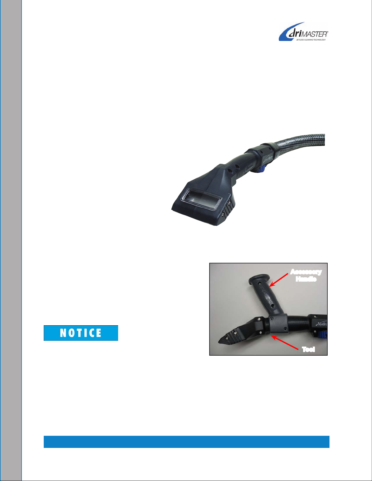
The patented DriMaster HiFlo Upholstery Tool, shown in Figure 1-1, is perfect for cleaning
upholstery, fabric and stairs. Because of its Jetless Cleaning Technology, it has no trigger
valve, no spray jet and never needs a separate dry pass.*
The tool’s new design incorporates
light weight, extremely durable
materials, giving the tool increased
levels of strength and comfort.
The DriMaster HiFlo Upholstery Tool
accommodates high volume jobs
where production rate is important.
It is capable of solution ow rates
for jobs that require a ushing action
which makes the tool particularly
efcient for stair cleaning.
DriMaster HiFlo Upholstery ToolFigure 1-1.
An optional accessory handle, shown attached
to the tool in Figure 1-2, is available to increase
comfort on long cleaning jobs.
We trust that you will enjoy many years of reliable
upholstery cleaning with the DriMaster HiFlo
Upholstery Tool.
The DriMaster HiFlo Upholstery Tool can be
used with a variety of HydraMaster cleaning
systems.
* U.S. patent No. 6,243,914; 7,070,662; Re39,623; D590,111
New Zealand patent No. 549645
Other U.S. and Foreign patents pending
Accessory
Handle
Tool
Optional Accessory Figure 1-2.
Handle Attached to Tool
1-1: General Information
Page 6
COnTACT InFOrMATIOn
If you have any questions regarding the operation, maintenance or repair of this upholstery
tool, please contact your local distributor.
To nd a local distributor, please visit our website at http://www.hydramaster.com/owners/
locate/index.asp.
If your question cannot be resolved by your distributor or by the information within this
manual, you may contact HydraMaster Customer Service direct using the following phone
numbers.
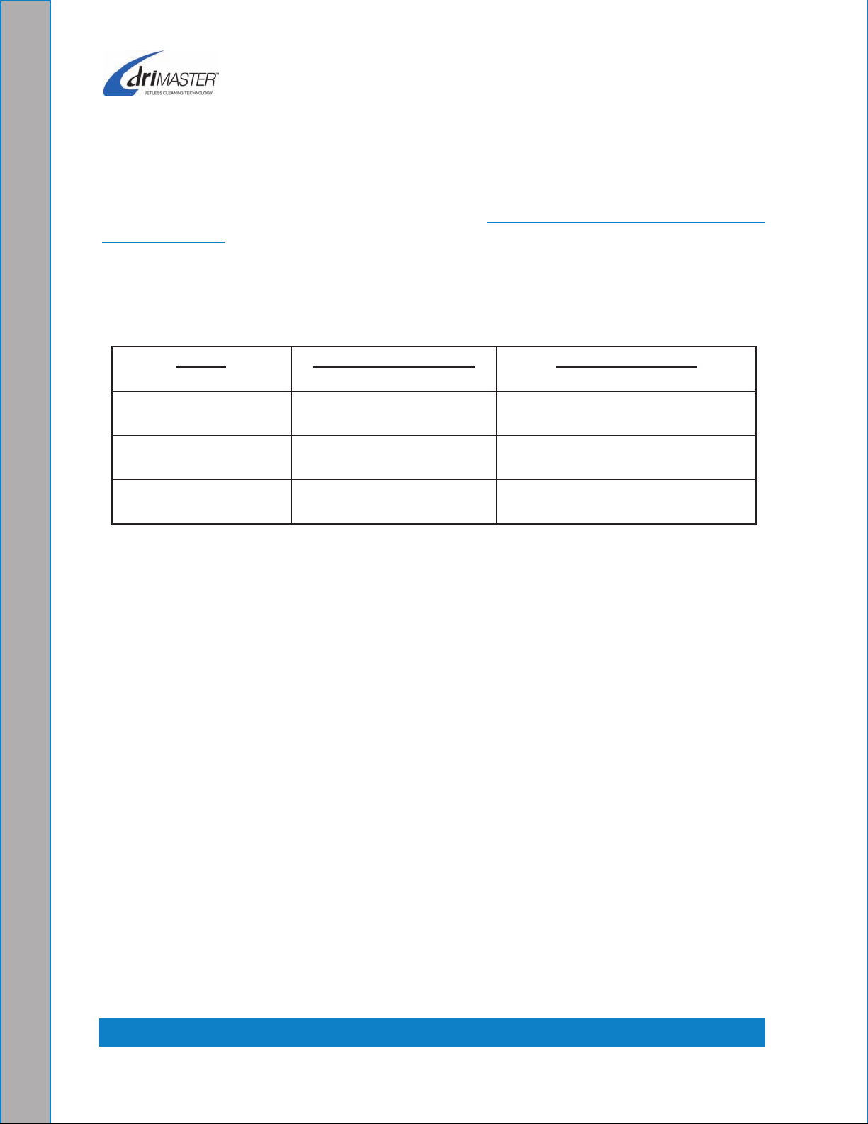
Hours Telephone numbers E-mail Addresses
Monday-Friday (425) 775-7275 Service
7:00 a.m. to 5:00 p.m. (425) 775-7276 parts
Pacic Standard Time
(800) 426-4225 parts /
Service FAX
techsupport@hydramaster.com
Tech Support:
parts Support:
parts@hydramaster.com
When calling your distributor, be sure to reference the serial number and date of
purchase.
FOr YOUr rEFErEnCE:
Serial no.____________________________________________________
Date of Purchase:_____________________________________________
Purchased From (Distributor): __________________________________
General Information: 1-2
Page 7
WArnIngS, CAUTIOnS AnD nOTICES
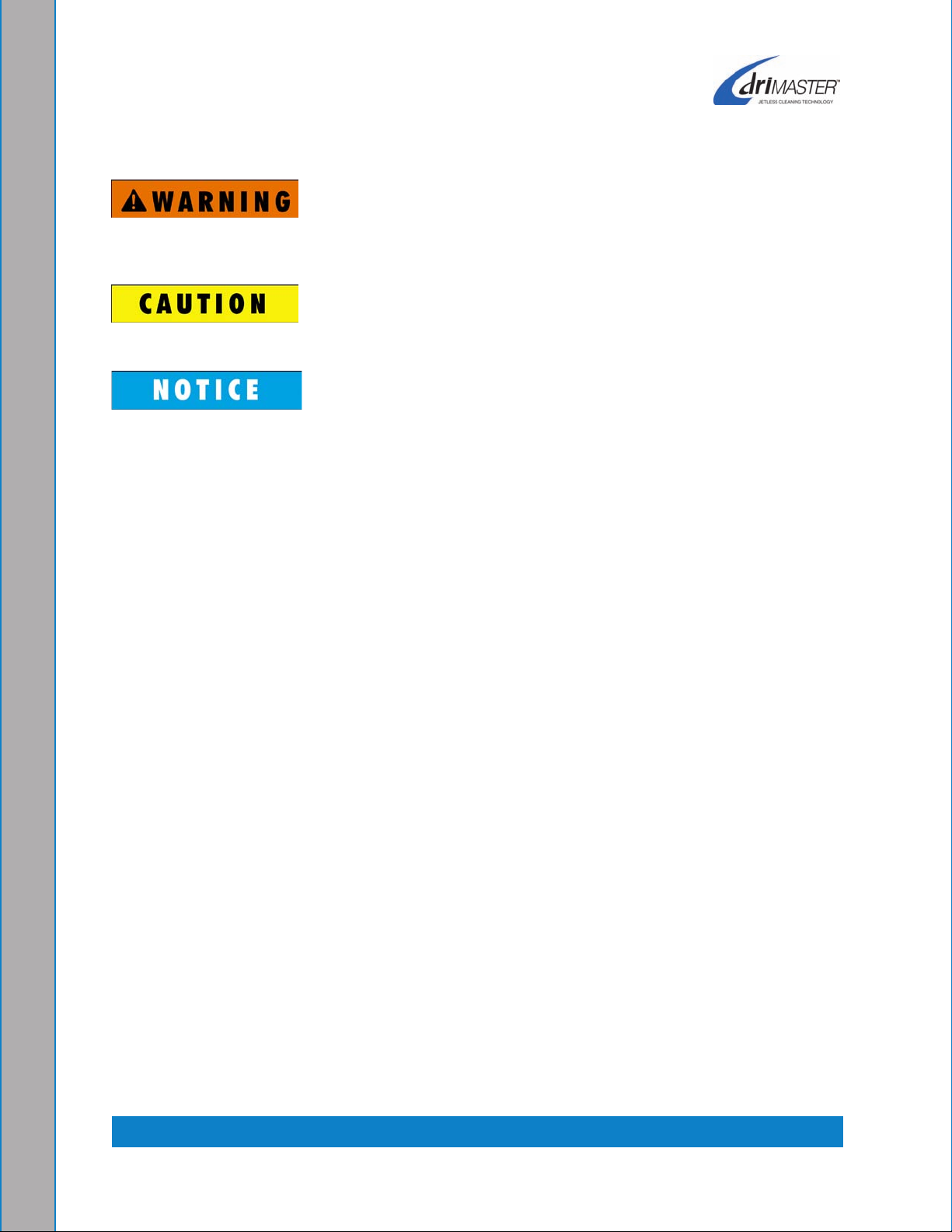
HydraMaster uses this WARNING symbol throughout the manual to warn of
possible injury or death.
This CAUTION symbol is used to warn of possible equipment damage.
This NOTICe symbol indicates that federal or state regulatory laws may apply,
and also emphasizes supplemental information.
1-3: General Information
Page 8

General Information: 1-4
Page 9
2 - Operating Instructions
your DriMaster HiFlo Upholstery Tool has been engineered using the latest and most
sophisticated technology available to produce the nest upholstery cleaning results
possible. Despite this, it remains only a tool of the upholstery cleaning trade and can
produce only as a good a job as the person operating it.
HydraMaster strongly recommends attending an Institute of Inspection, Cleaning
and Restoration Certication (IICRC) approved Upholstery Cleaning course as
soon as possible and to always follow the IICrC guidelines when cleaning.
OPTIOnAl ACCESSOrY HAnDlE ASSEMblY
The DriMaster HiFlo Upholstery Tool can be equipped with an optional accessory handle
(purchased separately) to increase comfort and control during difcult or extended
repetitious use of the upholstery tool.
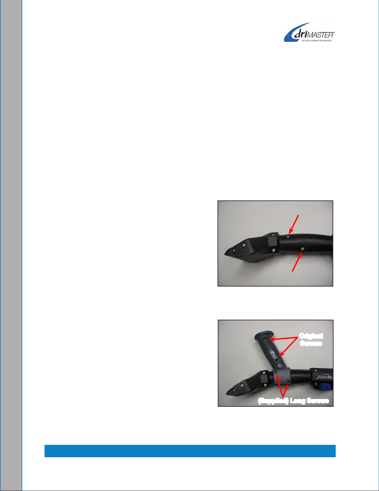
1.
Remove the two screws, nuts, and washers
found on the handle grip portion of the tool
(Figure 2-1). These parts will be reused in
fastening the handle.
Attach the accessory handle as shown in 2.
Figure 2-2. The original shorter screws, nuts,
and washers are used on the upper handle.
The longer supplied screws, nuts and washers
are used to connect the handle to the tool
body.
Remove Tool Figure 2-1.
Screws
Original
Screws
(Supplied) long Screws
Attach Accessory Figure 2-2.
Handle
2-1: Operating Instructions
Page 10

bEgIn ClEAnIng
Solution Bar Jet
Solution Control Knob
Solution Quick
Connect
Vac Hose Manifold
Do not use the DriMaster HiFlo Upholstery Tool on a machine exceeding 14” Hg
vacuum and 500 psi solution pressure. personal injury could result.
Attach the solution hose to the solution quick connect. A 1 ½” - 2” vacuum hose can 1.
be attached to the vac hose manifold (see Figure 2-3).
Attach Solution Hose and Adjust Water VolumeFigure 2-3.
2.
Adjust the water volume by turning the solution control knob. Turning the knob
counterclockwise increases the water volume; turning the knob clockwise decreases
the water volume. The amount of water volume you need will vary with the type of
machine you are cleaning with and the type of material you are cleaning.
To begin adjustment, make sure the cleaning machine is running and both vacuum
3.
and solution hoses are connected.
Slowly open the solution control knob until water is owing across the entire bar jet
4.
(without overspray).
Operating Instructions: 2-2
Page 11

When the solution knob is turned toward the
“HiFlo” position, the water will form a sheet across
the solution bar jet (see Figure 2-4)
The amount of vacuum and pressure produced
by your machine will determine the overspray
on the solution bar jet. The patented solution
bar jet makes a trigger valve unnecessary.
Turning Knob to Figure 2-4.
“HiFlo” Position Forms Sheet of
Do not touch the solution bar jet during
Water Across bar Jet
operation or immediately afterward; doing so
may cause severe burns!
When cleaning stairs, do not allow the tool to come into contact with the tack strip
along the edges of the stairs. The tool’s cleaning surface will be damaged by the
tack strip. equipment damage such as this is not covered by warranty.
It may be necessary to periodically clean the inside of the tool, hose and manifold.
Debris can build up over time, restricting the vacuum ow (see Figure 3-6).
2-3: Operating Instructions
Page 12

Operating Instructions: 2-4
Page 13

3 - Tool Maintenance
rEMOVIng AnD rE-InSTAllIng THE ClEAr WInDOW COVEr
Remove vacuum hose cuff from 1. DriMaster HiFlo Upholstery Tool and disconnect the
solution hose quick connect as shown in Figure 3-1.
lightly heating the “cuff” with a heat gun will make the cuff easier to remove and
install.
Remove the solution control knob by removing the 8/32” set screw as shown in
2.
Figure 3-2.
loosen, but do not remove, the valve retention nut (see arrow in 3. Figure 3-3).
Remove all screws from both sides of the tool (see
4. Figure 3-3) and carefully separate
the tool halves (see Figure 3-4).
Figure 3-1. Remove Vacuum
Hose Cuff
Valve Retention Nut
Figure 3-3. Remove Screws Figure 3-4. Separate Cover Halves
Figure 3-2. Remove Knob
3-1: Tool Maintenance
Page 14

Slide the clear window cover off of the tool body.5.
To re-install the clear window cover, slide it into one 6.
half of the tool body (see Figure 3-5). Then slide
the other half of the body into the window.
The clear window has grooves on either side that slide
onto the edges of the cutouts in the tool bodies.
Figure 3-5. Slide Cover into
Half of Tool body
The wear plates must be aligned and slid onto the tool halves at the same time
as the cover.
The window cover may come out if not installed properly.
Continue to assemble the two halves of the tool together, with the clear window 7.
being captured in the cutouts. Careful attention must be paid when sliding the two
body halves together.
Re-install the screws.
8.
Tighten the valve retention nut. Do not overtighten.9.
ClEAnIng THE SOlUTIOn bAr JET
The solution bar jet needs to be cleaned with a
.020” feeler gauge.
Slide the feeler gauge into the 1. small slot.
Gently slide the gauge back and forth to
2.
clear any debris from the opening (see
Figure 3-6).
Figure 3-6. Clean Debris from
Opening
Use only a feeler gauge to clean the slot in
the bar jet. Use of any other implement (paper clip, knife blade) may damage the
opening and seriously reduce the cleaning effectiveness of the upholstery tool.
Tool Maintenance: 3-2
Page 15

HydraMaster recommends you clean the lter
BYDATECODEREVISIONLTR
REVISIONS
CHKD APPVD
D
UPDATE DRAWING TO REFLECT DESIGN
CHANGES.
LRIP 11/05/2008 K.W. L.R.K. L.R.K.
E
000-052-541 WAS 000-052-739, 000-076-088 WAS
000-076-084.
1593 09/29/2009 R.D.M. L.R.K. L.R.K.
4
3
2
1
E
F
1.00
±0.25
120
±2
2.50
±0.25
4.00
±0.25
1.50
6.00
±0.050
C
1
B
5
4
3
7
6
DETAIL B
SCALE 1 : 2
2
D
REVISIONS
LTR
REVISION
CODE
DATE
BY
CHKD
APPVD
B
WRONG P/N FOR ITEM 3. WAS 000-049-042.
LRIP
11/13/2007
G.T.
L.R.K. L.R.K.
C
ADD 000-180-023.
1593 09/29/2009
R.D.M.
L.R.K. L.R.K.
D
CORRECT DIM OVERSIGHT, 120±2 WAS 120±0.
1593 10/1/2009
R.D.M.
L.R.K. L.R.K.
7 1
HOUSING, 1/4" BRASS FILTER
BRASS
000-052-171
- - -
6 1
QUICK CONNECT, 440 MALE W/ VITON STD
BRASS
000-052-050
- - -
5 1
NUT, BRASS JET X 1/4" FNPT
BRASS
000-094-118
- - -
4 1
ORIFICE, PLATE 0.045"
300 SERIES
S.S.
000-180-023
- - -
3 1
FILTER CARTRIDGE,1/4"BRASS
BRASS
000-049-052
- - -
2 1
QUICK CONNECT, FEMALE, 1/8" - OPEN
BRASS
000-052-434
- - -
1 1
HOSE, HIDE-A-HOSE RAW
VARIOUS
- - - - - -
ITEM NO.
QTY.
DESCRIPTION
MATERIAL
PART NO. DWG. NO.
D
C
B
7
6
5
4
3
2
1
E
F
UNLESS OTHERWISE NOTED
DIMENSIONS ARE IN INCHES
BREAK ALL SHARP EDGES 0.005-.015
TOLERANCES
.X= .1
.XX= .03
11015 47th Avenue West,
Mukilteo, Washington 98275
PROPRIETARY INFORMATION
125
MACHINE
FINISH
cartridge and orice plate on a periodic basis
to eliminate hard water deposit buildup. Both
components are conveniently located in the
solution quick connect subassembly.
DriMaster HiFlo Upholstery Tools manufactured
before April 9, 2009 will not include the Bar Jet
Assembly (p/N 000-076-088) and therefore will not
include the lter and orice.
Solution Quick Connect
Disassemble Figure 3-7.
Disassemble the solution quick connect to gain access
to the lter cartridge and orice plate (see Figure 3-7
through Figure 3-9).
Orice Plate
ClEAnIng THE FIlTEr CArTrIDgE
AnD OrIFICE PlATE
Remove the lter cartridge and orice plate, place 1.
them in a cup full of white vinegar and soak for
30 minutes.
Clean the orice plate’s opening with a wooden 2.
skewer or similar tool such as a plastic pick.
Cartridge
Filter
Remove Filter Figure 3-8.
Cartridge and Plate Orice
Do not use a metal object to clean the opening of
the orice plate; doing so can damage the plate.
Remove both parts from the vinegar and thoroughly rinse
3.
them with clear water.
Re-assemble the solution quick connect, re-installing the
4.
lter cartridge and orice plate in the proper order (see
arrows in Figure 3-9).
Do not operate the DriMaster HiFlo Upholstery Tool without
the orice plate. If you do not properly re-install the orice
plate in the solution quick connect (see Figure 3-9),
equipment damage could result. Such equipment
damage is not covered by warranty.
re-assemble Figure 3-9.
Solution Quick Connect
3-3: Tool Maintenance
Page 16

Tool Maintenance: 3-4
Page 17

4 - Assemblies and
parts lists
This section contains all the assemblies and parts lists associated with the upholstery
tool:
Handpiece Assembly parts lis t
Accessory Handle Assembly parts list
Hide-A-Hose Assembly parts list
4-1: Assemblies and parts lists
Page 18

6960 Rev. e
REVISIONS
D
UPDATE DRAWING TO REFLECT DESIGN
CHANGES.
E
000-052-541 WAS 000-052-739, 000-076-088 WAS
000-076-084.
5
4
3
2
17
7
6
5
10
17
11
15
14
1
9
72 14 9 16
9
10 6
5
138
4
12
9
3
9
16
Handpiece AssemblyFigure 4-1.
(p/N 000-143-374) Included
with p/N 000-061-146
Set Screw
Assemblies and parts lists: 4-2
Page 19

Handpiece Assembly Parts list
Item Part number Description Qty
1 000-076-088 Jet, DriMaster S/S HiFlo Bar Assembly - Formed * 1
2 000-105-533 plate, Wear - DriMaster HiFlo 2
3 000-061-138 Handle, Handpiece, left, DriMaster HiFlo 1
4 000-169-014 Valve, Ball 1
5 000-052-762 1/8” NpT X 1.5 1
6 000-052-433 Quick Disconnect, Male 1/8” NpT 1
7 000-061-139 Handle, Handpiece, Right, DriMaster HiFlo 1
8 000-174-168 Washer, Flat Mil Spc 1
9 000-174-167 Washer, Flat, .248 O.D. X .128 I.D. X .029 Thk 12
10 000-094-063 Nut, #6-32UNC Nylock 8
11 000-041-445 Cover, DriMaster HiFlo Window 1
12 000-052-541 1/8” NpT X .1875 O.D. 1
13 000-061-146 Assembly, Knob Custom Insert with label 1
14 000-143-576 Capscrew, Socket Head, 6-32 X 5/16 4
15 000-143-577 Capscrew, Socket Head, 6-32 X 3/4 2
16 000-143-578 Capscrew, Socket Head, 6-32 X 7/8 6
17 000-068-667 Hose, Hide-A-Hose Assembly 1
* DriMaster HiFlo Upholstery Tools manufactured before April 9, 2009 will not
include this Bar Jet Assembly (p/N 000-076-088) and therefore will not include
the lter and orice (see Figure 4-4).
4-3: Assemblies and parts lists
Page 20

6958 Rev. B
5
3
1
2
4
REVISIONS
LTR
REVISION
CODE
DATE
BY
CHKD
A
REMOVED SPECIFIC MAT'L; ITEM 1 & 2
LRIP
11/13/2007
GT
LRK LRK
B
CHANGED ITEM 4, NOW IS NYLOC NUT
LRIP
9/17/2008
AJP
EJ EJ
6
5
4
3
2
1
Accessory Handle AssemblyFigure 4-2.
Accessory Handle Assembly Parts list
Item Part number Description Qty
1 000-061-142 Handle, Accessory, Right 1
2 000-061-141 Handle, Accessory, left 1
3 000-174-167 Washer, Flat, .248 O.D. X .128 I.D. X .029 Thk 2
4 000-094-063 Nut, #6-32UNC Nylock 2
5 000-143-579 Cap Screw, Socket Head, #6-32 X 2 2
Assemblies and parts lists: 4-4
Page 21

6959 Rev. D
120
±2
1
DETAIL B
SCALE 1 : 2
2
D
REVISIONS
LTR
REVISION
B
WRONG P/N FOR ITEM 3. WAS 000-049-042.
C
ADD 000-180-023.
D
CORRECT DIM OVERSIGHT, 120±2 WAS 120±0.
8
7
6
5
4
3
2
Hide-A-Hose Assembly - Parts View 1 of 2Figure 4-3.
See Figure 4-4 for details
4-5: Assemblies and parts lists
Page 22

6959 Rev. D
2.50
±0.25
4.00
±0.25
1.50
1
5
4
3
7
6
SCALE 1 : 2
Hide-A-Hose Assembly - Parts View 2 of 2Figure 4-4.
Assemblies and parts lists: 4-6
Page 23

Hide-A-Hose Assembly Parts list
Item Part number Description Qty
1 - - - Hide-A-Hose Raw 1
2 000-052-434 Quick Connect, Female, 1/8” - Open 1
3 000-049-052 Filter Cartridge,1/4” Brass * 1
4 000-180-023 Orice, Plate 0.045” * 1
5 000-094-118 Nut, Brass Jet X 1/4” FNpT 1
6 000-052-050 Quick Connect, 440 Male W/ Viton Std 1
7 000-052-171 Housing, 1/4” Brass Filter 1
* DriMaster HiFlo Upholstery Tools manufactured before April 9, 2009 will not
include the Bar Jet Assembly (p/N 000-076-088) and therefore will not include
the lter and orice.
4-7: Assemblies and parts lists
Page 24

Assemblies and parts lists: 4-8
Page 25

5 - How to Order parts
From time to time, cleaning equipment may wear or malfunction. To obtain a proper
diagnosis of your malfunction, and to order warranty replacement parts or arrange for
repairs, it is important that you proceed in the following manner:
WArrAnTY PArTS OrDErS
Call the local distributor where you purchased your equipment and ask for the 1.
Service Department.
Have the following information ready:
2.
equipment Model a.
Date of purchase b.
Description of Malfunctionc.
Once it has been determined which parts are needed to correct the problem with 3.
your tool, make arrangements with your distributor to either perform the repairs or
ship the parts to you.
PArTS OrDErS
Call your local distributor. In most instances, they either stock or have access to parts
through a regional service center.
EMErgEnCIES
If, for any reason, your distributor is unable to supply you with the necessary parts, they
may call us and arrange for expedited shipping.
HydraMaster sells parts only through authorized distributors and service centers.
HydraMaster warranty covers only defective materials and/or workmanship for the periods
listed. Labor and/or diagnostic reimbursement is specically excluded.
5-1: How to Order parts:
Page 26

How to Order parts: 5-2
Page 27

6 - Warranty Information
All parts of the DriMaster HiFlo upholstery tool are warranted against defects for one
year.
Freezing, hard water, the use of unapproved solvents and/or abuse will void the
warranty.
HydraMaster warranty covers only defective materials and/or workmanship for the period
listed. Labor and/or diagnostic reimbursement is specically excluded.
If you have moved to a new area or have purchased a used machine and need information
regarding your local distributor, call HydraMaster at (425) 775-7272 or email us at:
custsvc@hydramaster.com.
6-1: Warranty Information:
Page 28

Warranty Information: 6-2
 Loading...