

Page 1
HYDRAMASTER
I
6323 204th Street SW, Lynnwood, WA 98036
CrossFire 3.7
Corporation
Machine Serial Number
Copyright G 1996
HYDRAMASTER@ Corporation
Lynnwood, Washington
182-020
No part of this manual may be reproduced or used in any form or by any means (i.e. graphic, electronic, photocopying or
electronic retrieval systems) without the express written permission of the HYDRAMASTER” Corporation. All rights reserved.
Revised January 25, 1996
Page 2
Table of Contents
CrossI%e 3.7
GENERAL INFORMATION . . . . . . . . . . . . . . . . . . . . . . . . . . . . . . . . . . .. 1-1
Telephone Numbers . . . . . . . . . . . . . . . . . . . . . . . . . . . . . . . . . ..1-2
System Operation . . . . . . . . . . . . . . . . . . . . . . . . . . . . . . . . . ...1-3
Machine Specifications . . . . . . . . . . . . . . . . . . . . . . . . . . . . . . ...1-4
Spare Parts Recommendation . . . . . . . . . . . . . . . . . . . . . . . . . ...1-6
Spare Parts List . . . . . . . . . . . . . . . . . . . . . . . . . . . . . . . ..1-6
Purchaser’s/Salesman’sResponsibility . . . . . . . . . . . . . . . . . . . . . . 1-8
Vehicle Preparation . . . . . . . . . . . . . . . . . . . . . . . . . . . . . . . . ...1-10
Installation Suggestions . . . . . . . . . . . . . . . . . . . . . . . . . ...1-11
Local Water Precautions.. . . . . . . . . . . . . . . . . . . . . . . . . . . . ...1-15
Wastewater Disposal Advisory . . . . . . . . . . . . . . . . . . . . . . . 1-16
I
Map . . . . . . . . . . . . . . . . . . . . . . . . . . . . . . . . . . . . . . . . .1-18
!
CLEANING PROCEDURES . . . . . . . . . . . . . . . . . . . . . . . . . . . . . . . . ...2-1
PH Chart . . . . . . . . . . . . . . . . . . . . . . . . . . . . . . . . . . . . . . . . .. 2-4
OPERATING INSTRUCTIONS . . . . . . . . . . . . . . . . . . . . . . . . . . . . . . ...3-1
Start Up . . . . . . . . . . . . . . . . . . . . . . . . . . . . . . . . . . . . . . . . ...3-1
Shut Down . . . . . . . . . . . . . . . . . . . . . . . . . . . . . . . . . . . . . . ...3-2
Precautions . . . . . . . . . . . . . . . . . . . . . . . . . . . . . . . . . . . . . . ...3-3
FREEZE GUARD . . . . . . . . . . . . . . . . . . . . . . . . . . . . . . . . . . . . . . . . .. 4-1
Vacuum Freeze Guard Procedure . . . . . . . . . . . . . . . . . . . . . . . ...4-1
HydraMaster Corporation
4/13/95
Page 3
CrossFire 3.7
Anti-Freeze Procedure . . . . . . . . . . . . . . . . . . . . . . . . . . . . . . ...4-2
WATER AND CHEMICAL SYSTEMS. . . . . . . . . . . . . . . . . . . . . . . . . . . .. 5-1
Water Flow . . . . . . . . . . . . . . . . . . . . . . . . . . . . . . . . . . . . . . ...5-1
Water Flow Diagram . . . . . . . . . . . . . . . . . . . . . . . . . . . . . . . . ...5-3
Proportioned Diagram . . . . . . . . . . . . . . . . . . . . . . . . . . . . . . . ...5-4
Chemical Tank Troubleshooting . . . . . . . . . . . . . . . . . . . . . . . . . . . 5-6
HIGH PRESSURE PUMP..... . . . . . . . . . . . . . . . . . . . . . . . . . . . . . ...6-1
Pump Maintenance . . . . . . . . . . . . . . . . . . . . . . . . . . . . . . . . . ...6-1
Pump Service (Wet End)..... . . . . . . . . . . . . . . . . . . . . . . . . ...6-3
Pump Service (Hydraulic End). . . . . . . . . . . . . . . . . . . . . . . . . ...6-9
Pump Troubleshooting . . . . . . . . . . . . . . . . . . . . . . . . . . . . . . ...6-14
Assembly Drawing (Wet End) . . . . . . . . . . . . . . . . . . . . . . . . . ...6-16
Parts List (Wet End) . . . . . . . . . . . . . . . . . . . . . . . . . . . . . . . . ...6-17
Assembly Drawing (Hydraulic End) . . . . . . . . . . . . . . . . . . . . . . . ..6-18
Parts List (Hydraulic End)... . . . . . . . . . . . . . . . . . . . . . . . . . ...6-19
CLEANING WAND . . . . . . . . . . . . . . . . . . . . . . . . . . . . . . . . . . . . . ...7-1
Valve, Jet, Wand Assembly Drawings . . . . . . . . . . . . . . . . . . . . . . . 7-1
Valve, Jet, Wand Parts List.... . . . . . . . . . . . . . . . . . . . . . . . . .. 7-4
VACUUM SYSTEM . . . . . . . . . . . . . . . . . . . . . . . . . . . . . . . . . . . . . ...8-1
Blower Troubleshooting . . . . . . . . . . . . . . . . . . . . . . . . . . . . . ...8-3
Blower Instruction Booklet
HydraMaster Corporation
4/13/95
Page 4
CrossFire 3.7
—
ENGINE INFORMATION..,...,,, . . . . . . . . . . . . . . . . . . . . . . . . . . ,. 9-1
Engine Troubleshooting . . . . . . . . . . . . . . . . . . . . . . . . . . . .,..,,9-1
Briggs &Stratton Engine Specifications
Briggs &Stratton Operator’s Manual
ELECTRICAL SYSTEM .,....... . . . . . . . . . . . . . . . . . . . . . . . . . . . ..10-1
Wiring Diagram Machine...,.. . . . . . . . . . . . . . . . . . . . . . . . . ..10-2
MACHINE MAINTENANCE . . . . . . . . . . . . . . . . . . . . . . . . . . . . . . . . . .,11-1
Daily . . . . . . . . . . . . . . . . . . . . . . . . . . . . . . . . . . . . . . . . . . ,,11-1
Weekly, Monthly, Quarterly. . . . . . . . . . . . . . . . . . . . . . . . . . . ...11-2
De-scaling . . . . . . . . . . . . . . . . . . . . . . . . . . . . . . . . . . . , .,....11-3
Overall Care . ..m. ..m . . . . . . . . . . . . . . . . . . . . . . . . . , . . . ...11-3
Maintenance Logs
HOW TO ORDER PARTS.... . . . . . . . . . . . . . . . . . . . . . . ,,, .,,.,..12-1
WARRANTY INFORMATION.. . . . . . . . . . . . . . . . . . . . . . . . . . . . . . ...13-1
Golden Guarantee@
ACCESSORIES . . . . . . . . . . . . . . . . . . . . . . . . . . . . . . . . . . . . . . . . ...14-1
PRODUCT UPDATES . . . . . . . . . . . . . . . . . . . . . . . . . . . . . . . . . . . . . .. 15-1
HydraMaster Corporation
6/28/95
Page 5
r
Introduction
CrossFire 3.7
section 1-1
his manual contains installation and operation instructions as well as
T
information required for proper maintenance, adjustment and repair of
this unit. Since the first and most important part of repair work is the
correct diagnosis of the problem, component manual troubleshooting
charts have been included for your convenience.
Unlike a garden tractor, lawn mower or cement mixer, all having one or
two functions to perform, the truck-mounted carpet cleaning plant has
many functions to perform simultaneously.
F The engine has to run at a consistent RPM.
F The vacuum has to pull air and dirty water back from cleaning
site.
F The water pump provides stable pressure at proper water flow for
cleaning.
F The chemical has to be injected into the water stream at the right
concentration.
F The heating system must maintain proper heat.
F The vacuum tank must store dirty water until drained.
As you can see, it is not just a turn-key operation with one thing to worry
about, Does it start?!
HydraMaster Corporation
4/13/95
Page 6
CrossFire 3.7
The manufacturer uses this symbol throughout the manual to warn of
possible injury or death.
This symbol is used to warn of possible equipment damage.
Section l-2
HOURS
Monday - Friday
8:00 am to 5:00 pm
PACIFIC STANDARD T ME
(206) 775-7276 Parts
206) 775-7275
800) 426-4225
TELEPHONE
Service
Parts / Service FAX
HydraMaster Corporation 7118/95
Page 7
System Operation
CrossFire 3.7
Section 1-3
he CrossFire heat exchanger system is a highly engineered cleaning
T
plant designed by HydraMaster Corporation. The system utilizes a
dynamic heating system comprised of three separate exhaust heat
exchangers for capturing “free heat. ”
The water flow is as follows:
Water is fed into the machine under tap pressure. It flows through
one pre-heater and then is automatically combined with a cleaning
solution as it enters the mix tank. The solution is then picked up by
the high pressure pump and pressurized to the desired level. The
water then splits flow, as demanded by the operator. The majority
of the water flows to the by-pass valve assembly, then back through
the secondary exhaust heat exchanger, and back to the mix tank.
-F. –,–. .!–-–––.––1––1 1--- Cl–– –.––.. –L –.. Cl –-.-– c..–.. – L1–– .- –.–.
I ne wa_cer aemanaea ~y Tne opera~or TIOWS worn ~ne wa~er pump
through the primary exhaust heat exchanger then out to the cleaning
tool .
When the cleaning solution reaches a pre-set high temperature, it is
released from the system and directed to the recovery tank. Then cool
water enters the system to regulate the temperature.
As there is no guess work in the manufacture of these highly advanced
cleaning plants, there must be none in preparing it to get the job done in
the field. It is the purpose of this manual to help you properly understand,
maintain and service your cleaning plant. Follow the directions carefully
and you will be rewarded with years of profitable, trouble-free operation.
I
It is imperative that no section be overlooked when preparing for
operation of this equipment.
HydraMaster Corporation
4/13/’95
Page 8
Machine Specifications
CrossFire 3.7
Section 1-4
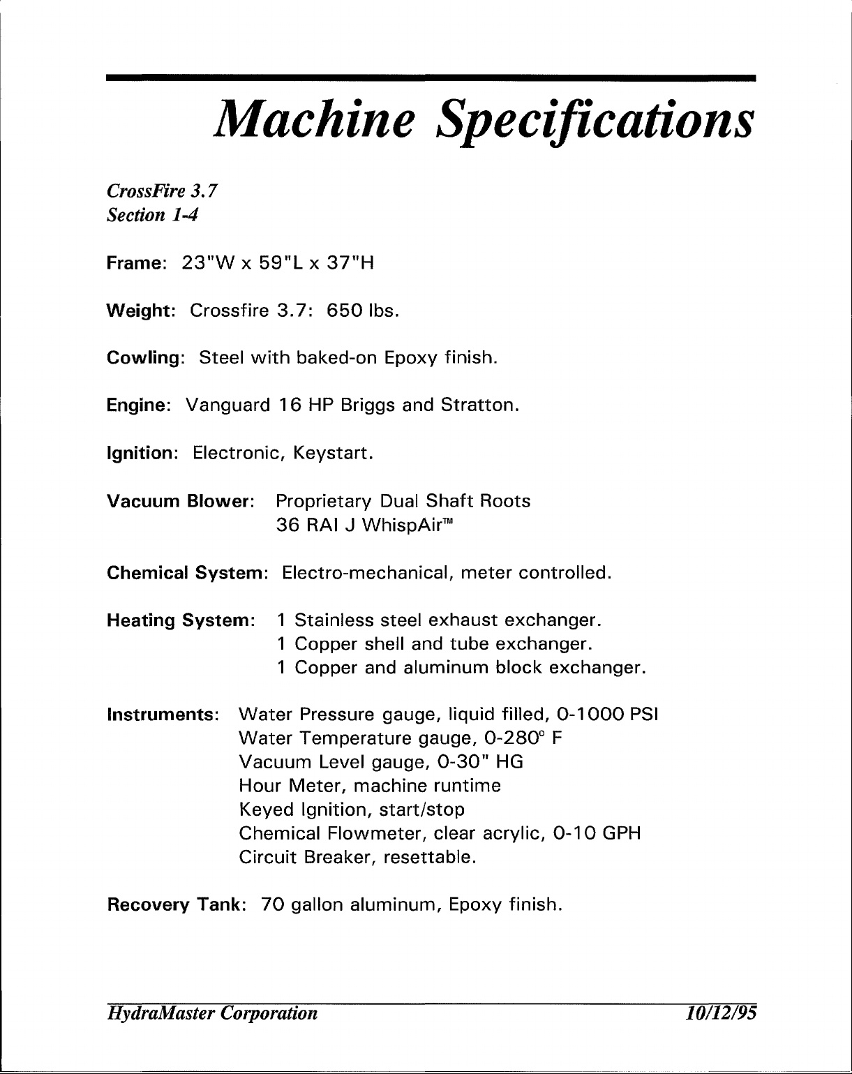
Frame: 23”W x 59”L x 37”H
Weight: Crossfire 3.7: 650 Ibs,
Cowling: Steel with baked-on Epoxy finish.
Engine:
Ignition:
Vacuum
Chemical System:
Heating System:
Instruments:
Vanguard 16 HP Briggs and Stratton.
Electronic, Keystart.
Blower: Proprietary Dual Shaft Roots
Water Pressure gauge, liquid filled, 0-1000 PSI
Water Temperature gauge, 0-280° F
Vacuum Level gauge, 0-30” HG
Hour Meter, machine runtime
Keyed Ignition, start/stop
36 RAI J WhispAirTM
Electro-mechanical, meter controlled.
1 Stainless steel exhaust exchanger.
1 Copper shell and tube exchanger.
1 Copper and aluminum block exchanger.
Chemical Flowmeter, clear acrylic, 0-10 GPH
Circuit Breaker, resettable.
Recovery Tank: 70 gallon aluminum, Epoxy finish.
HydraMaster Corporation
10/12/95
Page 9
CrossFire 3.7
Section 1-5
Cleaning Wand:
vacuum lips with stainless steel solution valve.
High Pressure Hose:
rated to 1250 PSI.
Vacuum Hose: 2“ reinforced, 1 %” reinforced.
Standard Equipment:
Stainless steel with heat shield. Grip
%” High temperature lined/vinyl
Machine Power Console
Full Instrumentation
WhispAirTM Vacuum Blower
CrossFire~ Water Heating Package
Deluxe Sound Suppression Package
Vacuum Recovery Tank
Carpet Cleaning Wand
Chemical Jug
Chemical Jug Holder
100 ft, 2“ Vacuum Hose
and replaceable
covered.
Hose
10 ft, 1 %” Wand Whip-line
10 ft, 1 %” Recovery Drain Line
100 ft, Super Flex Solution Line
Freeze Guard System
Battery Box with Holder
Van Decal Package
Van Installation Kit
Operation Manual
HydraMaster Jacket
HydraMaster Corporation
10/12/95
Page 10
Spare Parts
Crossfire 3.7
Section 1-6
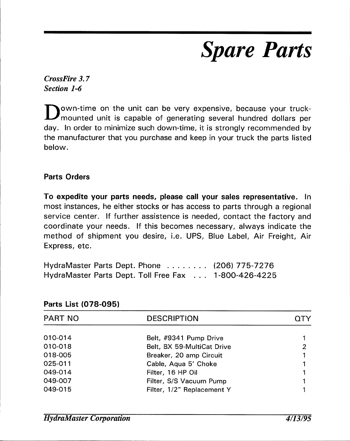
own-time on the unit can be very expensive, because your truck-
D
mounted unit is capable of generating several hundred dollars per
day. In order to minimize such down-time, it is strongly recommended by
the manufacturer that you purchase and keep in your truck the parts listed
below.
Parts Orders
To expedite your parts needs, please call your sales representative. In
most instances, he either stocks or has access to parts through a regional
service center. If further assistance is needed, contact the factory and
coordinate your needs. If this becomes necessary, always indicate the
method of shipment you desire, i.e. UPS, Blue Label, Air Freight, Air
Express, etc.
HydraMaster Parts Dept. Phone . . . . . . . . (206) 775-7276
HydraMaster Parts Dept. Toll Free Fax . . , 1-800-426-4225
Parts List (078-095)
PART NO
010-014 Belt, #9341 Pump Drive
010-018
018-005 Breaker, 20 amp Circuit
025-011
049-014
049-007
049-015
DESCRIPTION
Belt, BX 59-MuItiCat Drive
Cable, Aqua 5’ Choke
Filter, 16 HP Oil
Filter, S/S Vacuum Pump
Filter, 1/2” Replacement Y
QTY
1
2
1
1
1
1
1
Ilydraillaster Corporation
4/’13/95
Page 11
CrossFire 3.7
~
Section l-7
PART NO DESCRIPTION
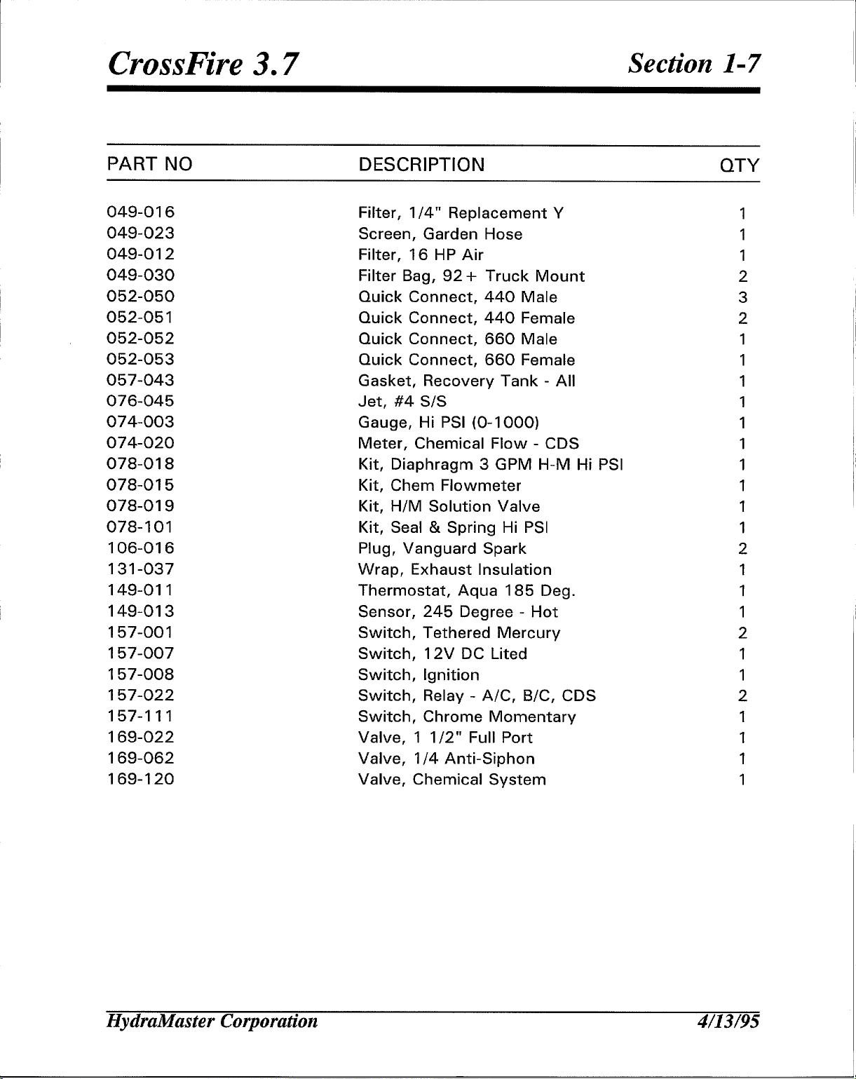
049-016
049-023
049-012
049-030
052-050
052-051
052-052
052-053
057-043
076-045
074-003
074-020
078-018
078-015
078-019
078-101
106-016
131-037
149-011
149-013
157-001
157-007
157-008
157-022
157-111
169-022
169-062
169-120
Filter, 1/4” Replacement
Screen, Garden Hose
Filter, 16 HP Air
Filter Bag, 92+ Truck Mount
Quick Connect, 440 Male
Quick Connect, 440 Female
Quick Connect, 660 Male
Quick Connect, 660 Female
Gasket, Recovery Tank - All
Jet, #4 S/S
Gauge, Hi PSI (O-1 000)
Meter, Chemical Flow - CDS
Kit, Diaphragm 3 GPM H-M Hi PSI
Kit, Chem Flowmeter
Kit, H/M Solution Valve
Kit, Seal & Spring Hi PSI
Plug, Vanguard Spark
Wrap, Exhaust Insulation
Thermostat, Aqua 185 Deg.
Sensor, 245 Degree - Hot
Switch, Tethered Mercury
Switch, 12V DC Lited
Switch, Ignition
Switch, Relay - A/C, B/C, CDS
Switch, Chrome Momentary
Valve, 1 1/2” Full Port
Valve, 1/4 Anti-Siphon
Valve, Chemical System
QTY
1
1
1
2
3
2
1
1
1
1
1
1
1
1
1
1
2
1
1
1
2
1
1
2
1
1
1
1
HydraMaster Corporation
4/13/95
Page 12
Responsibilities
I
I
Crossl%e
3.7
Section l-8
T
he Purchaser’s responsibilities are:
Prior to arrival of unit, install 5/8” exterior plywood flooring in the vehicle
and cover it with artificial turf.
Purchase heavy duty 42 ‘slow’ charge if new. If the battery is not fully charged, damage can
occur to the engine charging regulator.
Reading of owner’s manual: It is the purchaser’s responsibility to read the
60 amp hour battery and have the battery
unit operation manual and to familiarize himself with the information
contained therein.
Warnings.
The Sales Representative’s responsibilities
ACCEPTANCE OF SHIPMENT:
1. If the unit shows any outward signs
delivery receipt until you have closely
any damage on the delivery receipt.
2. The salesman from whom you purchased your unit is responsible for
supervising the correct installation of the unit in your vehicle and
Special attention should be paid to all Cautions and
are:
of damage, do not sign the
inspected the unit and noted
HydraMaster Corporation
4/13/95
Page 13
CrossFire 3.7
thoroughly training you in its operation, maintenance and precautions.
CORRECT INSTALLATION INCLUDES:
Installation of through-floor fittings for gasoline fuel lines;
Placing the unit and recovery tank in your vehicle and securing them
with bolts or tie down cleats;
Connecting gasoline lines;
Connecting the battery;
Checking the pump, vacuum blower and engine oil levels prior to
staring the unit;
Starting the unit to check engine and see that all systems function
normally;
Section l-9
Checking all hoses, wands, etc. for correct operation.
TRAINING SHALL INCLUDE:
A thorough review of the operation manual with purchaser;
Instruction and familiarization in: how to correctly start up and shut
down the unit, how to correctly clean with the unit, where and how
often to check and change component oil levels, how the unit’s
systems work, how to troubleshoot the unit, how to do basic
repairs, safety precautions and their importance, freezing damage
and how to avoid it, hard water damage and how to avoid it;
A thorough review of the unit warranty and warranty procedures.
HydraMaster Corporation
4/13/95
Page 14
Vehicle Prep
CrossFire 3.7
Section 1-10
he preferable vehicle for a CrossFire or ProFire installation is a cargo
T’
van witha heavy-duty suspension package. The van should have 3/4
ton capacity.
TRUCK PREPARATION
The manufacturer recommends the installation of plywood flooring,
covered with polypropylene backed astroturf (do not use rubber-backed),
in the vehicle prior to installation of machine.
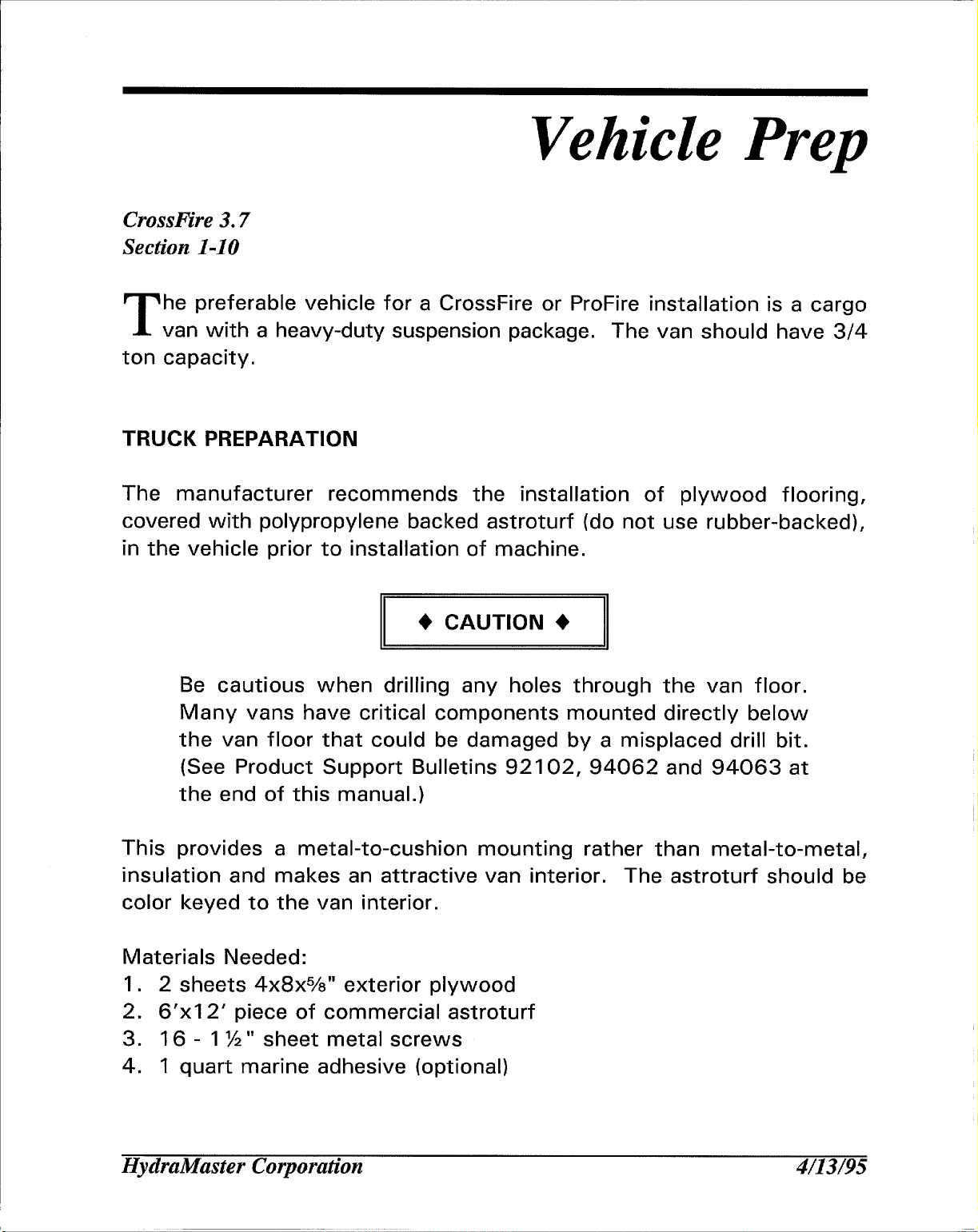
CAUTION +
+
II
Be cautious when drilling any holes through the van floor,
Many vans have critical components mounted directly below
the van floor that could be damaged by a misplaced drill bit.
(See product Support Bulletins 92102,
the end of this manual. )
This provides a metal-to-cushion mounting rather than metal-to-metal,
insulation and makes an attractive van interior. The astroturf should be
color keyed to the van interior.
Materials Needed:
1. 2 sheets 4x8xYs” exterior plywood
2. 6’xI 2’ piece of commercial astroturf
3. 16- 1 %” sheet metal screws
4. 1 quart marine adhesive (optional)
II
94062 and 94063 at
HydraMaster Corporation
4/13/95
Page 15
CrossFire 3.7
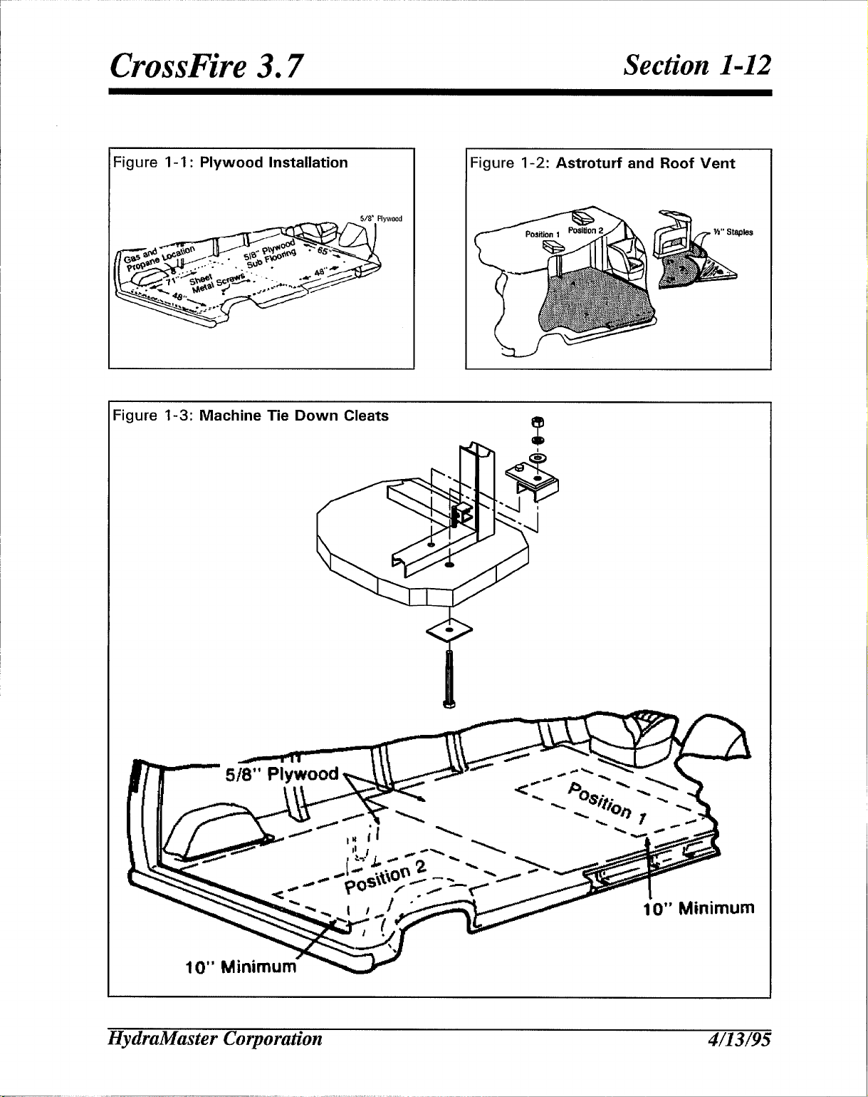
5. 1 staple hammer with %” staples
(See illustration for correct placement of plywood flooring)
ROOF VENTS
HydraMaster strongly recommends installation of roof vents in all
truckmount installations.
heaters, these must be vented through the roof of the van.
When installing equipment with propane
Section 1-11
PLACEMENT OF
There are two
illustrated in the
A, SIDE DOOR:
access for accessories and hoses as well as unobstructed access to the
component/working side of the machine, thus making it a bit easier to
perform maintenance and/or repair without removing the unit from the
truck.
B. REAR DOOR: Although this location partly limits working access, it
does direct the noise away from the cleaning site. Some cleaners in the
colder areas prefer this location because it puts the weight over the rear
wheels for better traction in ice and snow. Rear mounting requires the
unit to be slid to the right side as far as possible. This not only provides
adequate working space on the component side of the unit but also
improves weight distribution inside the van (engine and component weight
line up over drive shaft). Also, it is physically easier to load the unit into
UNIT IN VEHICLE
recommended unit placements described below and
following diagrams.
Most installations are side door.
This provides rear
the rear door due to the height of the van bed.
HydraMaster Corporation
4/13/95
Page 16
CrossFire 3.7
Section 1-12
Figure 1-1: Plywood Installation
Figure
-3: Machine Tie Down Cleats
‘igure 1-2: Astroturf and Roof Vent
la
HydraMaster Corporation
4/13/95
Page 17
CrossFire 3.7
.
Ensure that the machine is well secured to the floor of the van with the
hardware supplied. A sudden or crash stop will cause the machine to
rocket forward, all 750 Ibs. worth! Protect yourself and the machine.
SECURE IT!
Section 1-13
I
I
It is recommended by the manufacturer that the exhaust from the front of
the machine be vented down under the truck to prevent carbon monoxide
from entering the job site.
blowing away from the job site.
The manufacturer also recommends the installation of aluminum vents in
the truck roof to allow heat to escape.
Mount a fire extinguisher just inside the rear or side door for emergencies.
Never operate this machine with a portable gas can inside the truck.
Doing so increases the risk of a fire or explosion.
Transportation in a vehicle of any vented fuel container that presently
Always park the truck so the exhaust is
holds or has ever held a flammable liquid is strictly forbidden by
HydraMaster Corporation and by federal and state regulation.
HydraMaster Corporation
4/13/’95
Page 18
CrossFire 3.7
Do not use a portable propane tank inside of the truck or van. It is
dangerous and illegal in most states.
Section 1-1
HydraMaster Corporation 4/13/95
Page 19
—..———
Local Water Precautions
CrossFire 3.7
Section 1-15
he quality of water varies greatly.
T
minerals in the water which results in what is commonly called “hard
water”.
other parts of the machines causing damage and a loss of cleaning
effectiveness. This influences the reliability and efficiency of equipment
in direct proportion to the level of hardness.
I
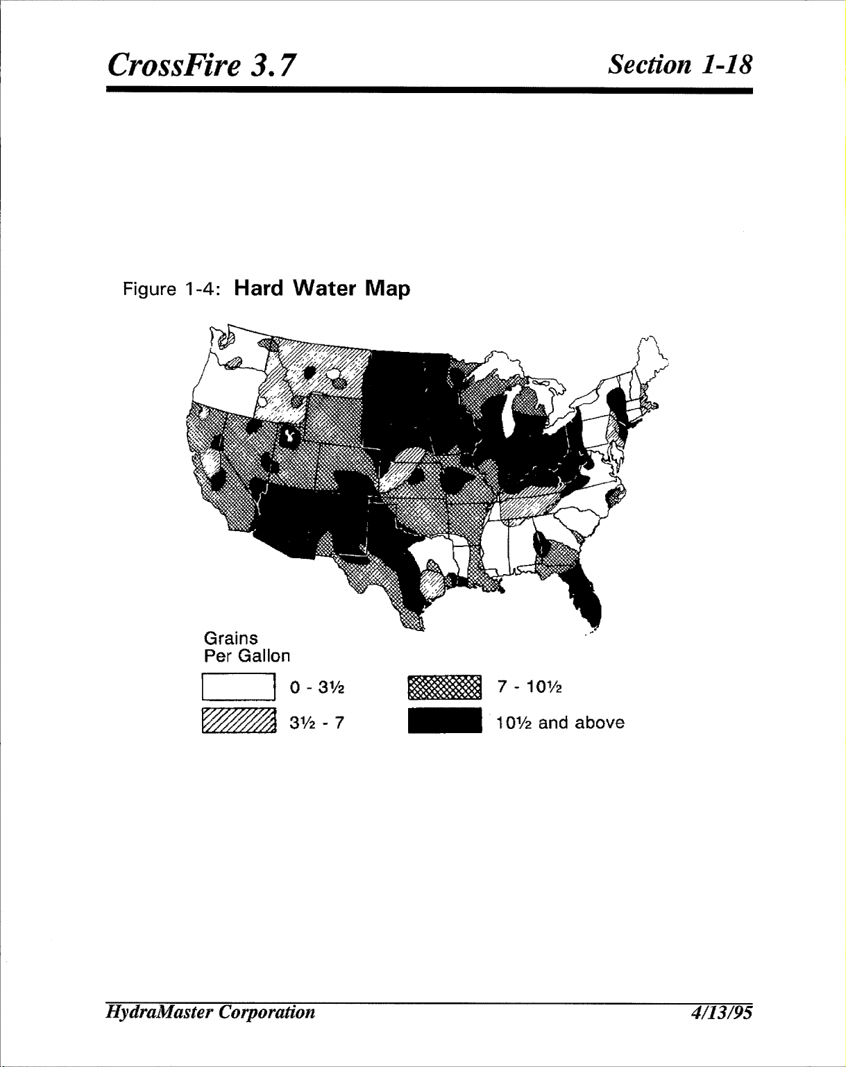
HARD WATER AREA MAP
The following map defines areas in the United States which compromise
fluid related components such as hoses, fittings, heaters, pumps, valves
and water cooled engines.
be obtained from geological societies.
WATER SOFTENER
These minerals tend to adhere to the insides of heater coils and
For other countries, hard water area maps can
Many areas have an excess of
Cleaning efficiency and equipment life is increased, chemical use
decreased, and the appearance of cleaned carpets enhanced when water
softeners are incorporated in hard water areas. The manufacturer strongly
urges the use of water softener units in areas exceeding 3 1/2 grains per
gallon, Using a hard water area map as a reference, determine the quality
of water in your area and take action immediately, if necessary.
Reports from several of our machine users commending the results of the
use of water softeners in conjunction with their machines prompts us to
recommend the procedure to everyone in a “hard water” area.
HydraMaster Corporation
4/13/95
Page 20
CrossFire 3.7
The relatively low cost of a water softener service is more than made up
for in the increased life of machine parts and continued cleaning
efficiency. The water softener will also increase the effectiveness of the
cleaning chemical being used and, therefore, less chemical will be needed.
Contact a water softener distributor in your area for information on the
rental of a simple water treatment unit to carry in your truck. Be sure to
change the water softener in accordance with the capability of the
softener, For example:
the machine uses an average of 30 gallons per hour, for an average of 5
hours a day, this equals 150 gallons per day. In 6 days the machine
would use 900 gallons of water. Therefore, the softener would need to
be changed every 6 working days for maximum softening.
If the softener will treat 900 gallons of water and
Section 1-16
WASTE WATER DISPOSAL ADVISORY
There are laws in most communities prohibiting the dumping of recovered
“gray” water from carpet cleaning in any place but a sanitary treatment
system.
This cleaning rinse water, recovered into your unit’s vacuum tank,
contains materials such as detergents.
being safe for streams, rivers and reservoirs.
IN ACCORDANCE WITH THE EPA, STATE AND LOCAL LAWS, DO NOT
DISPOSE OF WASTE WATER INTO GUTTERS, STORM DRAINS,
STREAMS, RESERVOIRS, ETC.
In most cases, an acceptable method of waste water disposal is to
discharge into a municipal sewage treatment system after first filtering out
solid material such as carpet fiber. Access to the sanitary system can be
obtained through a toilet, laundry drain, RV dump, etc. Permission should
first be obtained from any concerned party or agency.
These must be processed before
HydraMaster Corporation
4/’13/95
Page 21
CrossFire 3.7
I
One disposal method which usually complies with the law is to
accumulate the waste water and haul it to an appropriate dump site.
Another solution to the disposal problem is to equip yourself with an
Automatic Pump-Out System. These systems are designed to remove
waste water from the extractor’s recovery system and actively pump the
water through hoses to a suitable disposal drain. Properly designed, they
will continuously monitor the level of waste water and pump it out
Section 1-17
simultaneously to the cleaning operation.
process is that the operator does not have to stop his cleaning to empty
the recovery tank. HydraMaster makes an A.P. O. System available which
can be ordered with new equipment or installed later.
The penalties for non-compliance can be serious. A
laws and regulations to be sure you are in compliance
The hidden benefit of this
ways check local
HydraMaster Corporation 4/13/95
Page 22
CrossFire 3.7
Figure 1-4: Hard Water Map
Section 1-18
Grains
Per Gallon
n 0- 31/’,
3% -7
HydraMaster Corporation
10I’2
7 “
10% and above
4/13/95
Page 23
Cleaning and Chemicals
CrossFire 3.7
Section 2-1
our mobile carpet cleaning plant has been engineered using the latest
Y
and most sophisticated technology available to produce the finest
carpet cleaning results possible. Despite this, however, it remains only
a tool of the carpet cleaning trade, and it can produce only as good a job
as the person operating it.
PRECAUTIONS
There are no short cuts to good carpet cleaning. it requires time, cleaning
knowledge and the use of good chemicals. Therefore, the manufacturer
recommends the use of spotting agents and traffic lane cleaners, as
required, prior to the actual cleaning of carpeting,
The use of some chemicals through your mobile carpet cleaning plant can
seriously damage the internal plumbing, high pressure pump and heater.
These harmful chemicals include concentrated acid (see the pH chart at
the end of this section), solvents, and some paint, oil, and grease
removers with a high concentration of solvents.
The manufacturer recommends only the use of chemicals containing rust
and corrosion inhibitors and water softening agents to prevent chemical
build-up which may lead to component failure and warranty invalidation.
+ CAUTION +
The increased demand for “clear water” rinsing results in the need for
special care when using these acid based chemicals in your equipment,
HydraMaster Corporah”on 4/13/95
Page 24
CrossFire 3.7
The negative side of these products is the corrosive effects the acid can
have on metals, including swivels, pumps, heat exchangers, etc.
Section 2-2
HydraMaster’s
components.
damaged from
caused failures.
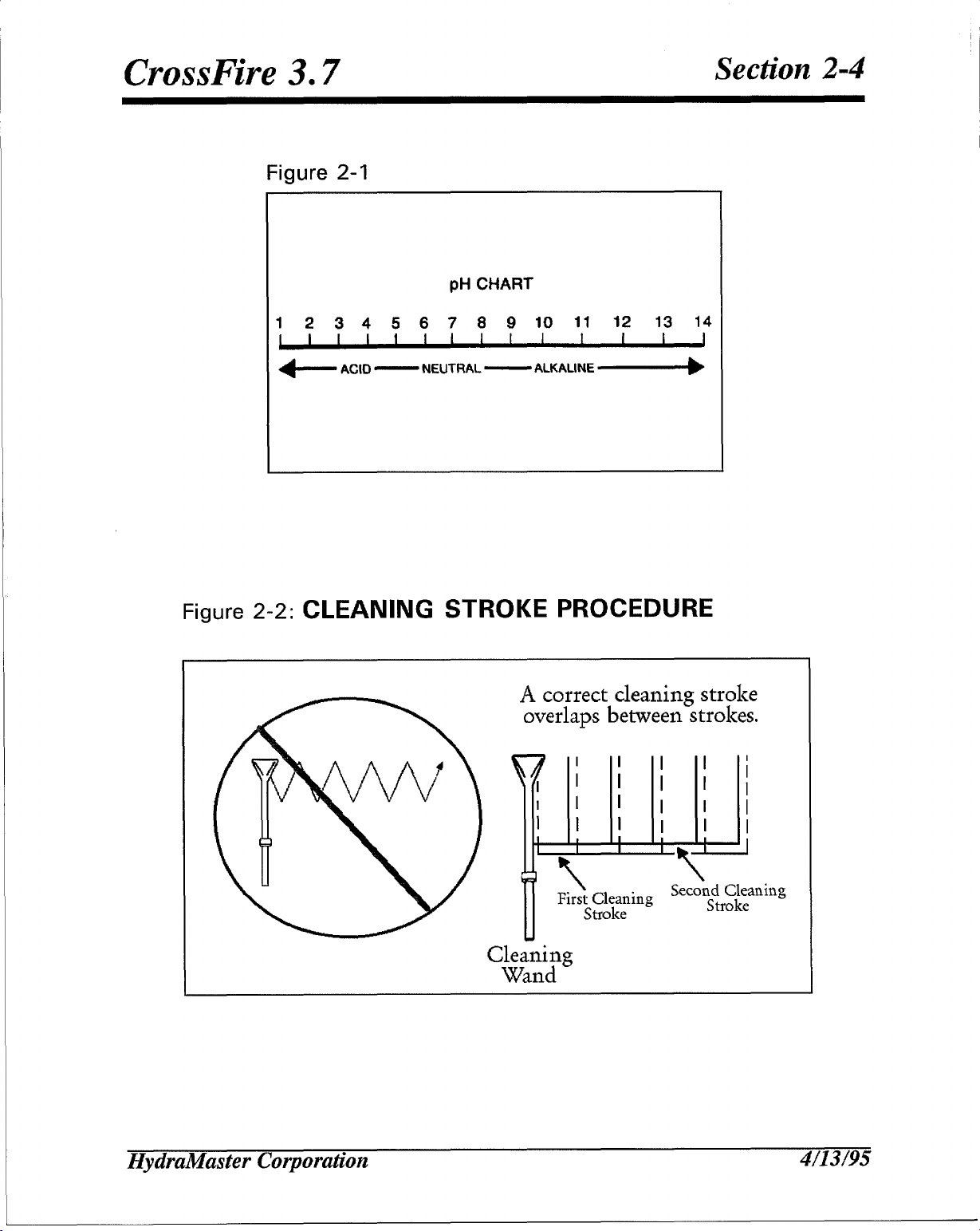
CLEANING STROKE PROCEDURE
Purpose: To eliminate excess moisture remaining in the carpet fiber and
the sawtooth appearance which results from diagonal movement of the
cleaning tool on all types of carpet.
Procedure: Always move the cleaning tool in smooth, forward and
backward strokes. Apply slight pressure to the forward stroke while the
solution is injected into the carpet. When extracting (drying), apply firm
pressure on the forward stroke to ensure a positive “lock” for the vacuum
and minimize the “hopping” effect resulting on carpet that is not smooth.
During the forward and reverse strokes, movement to the right or left
C/earWater Rinse has been formulated to protect vital
HydraMaster will not warranty parts that have been
using unprotected acid products that have obviously
should only be accomplished at the extreme rear of the stroke.
Overlapping is also important to ensure even application of solution and
prevent saturation when cleaning wand is stopped twice at the same
point at the rear of the cleaning stroke. This is illustrated at the end of
this section.
Failure to adopt this procedure can result in increased chance
streaks’, fiber shrinkage, brown-out and longer drying periods.
OVER-WETTING
Over-wetting is annoying to all concerned, and sometimes leaves a bad
HydraMaster Corporation
of ‘clean
4/13/’95
Page 25
CrossFire 3.7
Section 2-3
I
impression of the cleaning process used.
THESE ARE SEVERAL AREAS THAT WILL CAUSE OVER-WETTING
1. Too few vacuum strokes or improper saw-tooth vacuum strokes as
shown in the following illustration.
2. Obstructed, cut or kinked hoses.
3. Vacuum tank drain valve left partially open,
4. Clogged vacuum blower filter or vacuum tank lid not sealing
properly.
5. Cleaning a heavily foam-saturated carpet without defoamer. (We
recommend crystal type. )
HydraMaster Corporation 4/13/95
Page 26
CrossFire 3.7
Figure 2-1
112345678910 I1I2I3 14
Section 2-4
PH CHART
+— ACK)—
NEUTRAL —
ALKALINE~
Figure 2-2: CLEANING STROKE PROCEDURE
A correct cleaning stroke
overlaps between strokes.
I
I
I I
I
I I I /
I I I I I
I
I 1 I I [ I
,
I 1
1
I
1
1
HydraMaster Corporation
{
2 \
Flrs$$::ing
‘\’
Secotv~r~~eaning
4/13/95
Page 27
CrossFire 3.7
Section 3-1
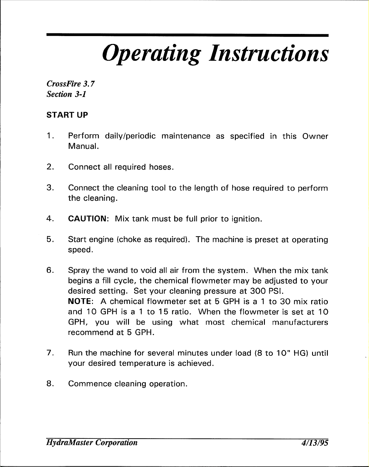
START UP
Operating Instructions
2.
3.
4.
5.
6.
1.
Perform daily/periodic maintenance as specified in this Owner
Manual.
Connect all required hoses.
Connect the cleaning tool to the length of hose required to perform
the cleaning.
CAUTION: Mix tank must be full prior to ignition.
Start engine (choke as required). The machine is preset at operating
speed.
Spray the wand to void all air from the system. When the mix tank
begins a fill cycle, the chemical flowmeter may be adjusted to your
desired setting. Set your cleaning pressure at 300 PSI.
NOTE: A chemical flowmeter set at 5 GPH is a 1 to 30 mix ratio
and 10 GPH is a 1 to 15 ratio. When the flowmeter is set at 10
GPH, you will be using what most chemical manufacturers
recommend at 5 GPH.
7.
8.
Run the machine for several minutes under load (8 to 10“ HG) until
your desired temperature is achieved.
Commence cleaning operation.
HydraMaster Corporation
4/13/’95
Page 28
CrossFire 3.7
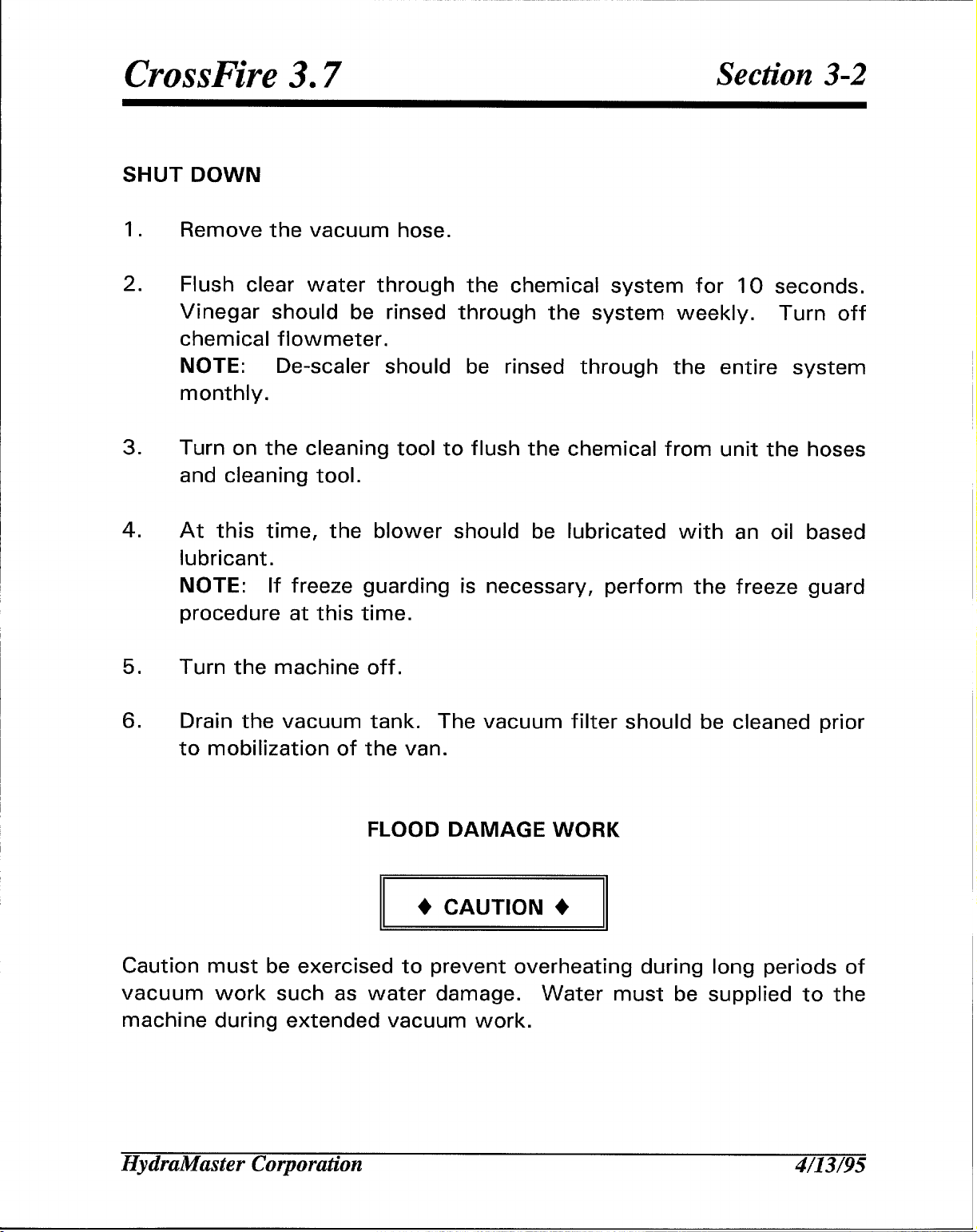
SHUT DOWN
Section 3-2
1,
2.
I
3.
4.
5.
Remove the vacuum hose.
Flush clear water through the chemical system for 10 seconds.
Vinegar should be rinsed through the system weekly. Turn off
chemical flowmeter,
NOTE:
monthly.
Turn on the cleaning tool to flush the chemical from unit the hoses
and cleaning tool.
At this time, the blower should be lubricated with an oil based
lubricant.
NOTE: If freeze guarding is necessary, perform the freeze guard
procedure at this time.
Turn the machine off.
De-scaler should be rinsed through the entire system
6.
Drain the vacuum tank. The vacuum filter should be cleaned prior
to mobilization of the van.
FLOOD DAMAGE WORK
+ CAUTION +
Caution must be exercised to prevent overheating during
vacuum work such as water damage.
machine during extended vacuum work.
Water must be supplied to the
ong periods of
HydraMaster Corporation 4/’13/95
Page 29
Precautions
CrossFire 3.7
Section 3-3
Ithough this unit has been factory adjusted, it may require additional
A
adjustments to achieve optimum performance, i.e. altitude may
require carb adjustment and ambient temperatures may require heat
control adjustment. When required, consult an authorized representative.
THROUGH-FLOOR DRILLING: Be cautious when drilling holes through the
van floor. Many vans have critical components mounted directly below
the van floor that could be damaged by a misplaced drill bit. (See product
Support Bulletins 92102, 94062 and 94063 at the end of the manual.)
ENGINE COOLING: Units employing air cooled engines must not be
enclosed within a van with doors and windows closed.
temperatures within the engine will result in premature engine failure and
a compromise of applicable warranty.
LEVEL OPERATION: During operation, van or trailer must be parked on
level ground not to exceed + or - 10 degrees. Failure to insure proper
leveling may prevent proper internal lubrication of engine, vacuum and/or
high pressure components.
HydraMaster Corporation
Excessive
10/12/95
Page 30
CrossFire 3.7
Section 3-4
n
MOVING PARTS: Never
Severe bodily injury may result.
ACID RINSE AGENTS: The increased demand for “clear water” rinsing
results in the need for special care when using these acid based chemicals
in your equipment.
effects the acid can have on metals, including swivels, pumps, heat
exchangers, etc.
HydraMaster’s C/earWater Rinse has been formulated to protect vital
components. HydraMaster will not warranty parts that have been
damaged from using acid products that have obviously caused failures.
touch any part of the machine that is in motion.
The negative side of these products is the corrosive
FREEZE PROTECTION: Mother nature gives little warning as to her cold
spells, Therefore, not protecting this equipment from freezing will result
in costly down-time. Placing an electric heater in the truck or parking the
truck indoors will help to insure against freezing, but should not be the
primary method of freeze protection.
EXHAUST SYSTEM: Do not allow flammable material (i.e. oil, fuel, plastic
or wood products) to come in contact with the exhaust system.
HydraMaster Corporation
10/12/95
Page 31

CrossFire 3.7
WARNING +
+
II
HOT SURFACES: During the operation of this equipment, many surfaces
on the machine will become very hot. When near the van for any reason,
care must be taken not to touch any hot surface, such as the heating
system, engine, exhaust, etc.
NO SMOKING: It is unsafe to smoke in or around the vehicle.
II
Section 3=5
WARNING +
+
II
CARBON MONOXIDE: This unit generates toxic fumes. Position the
vehicle so that the fumes will be directed away from the job site. Do not
park where exhaust fumes can enter a building through open doors,
windows, air conditioning units or kitchen fans.
TOXIC FUMES: Do not occupy the vehicle when the cleaning equipment
is operating. Toxic fumes may accumulate inside a stationary vehicle.
ENGINE EXHAUST: The engine exhaust from this product contains
II
chemicals know to the State of California to cause cancer, birth defects
or other reproductive harm.
HydraMaster Corporation
10/12/95
Page 32

~
IFWNFM-JIWMLIElt&mLs ‘WM!l: IN4K+WW Uplmmlwl ‘tlhk% Imtmlhillwt M&!iil’lh n Iplllwtdklllld gti%
mm h-’lslkke ‘tlhm ‘mdkll Immlgl MID
m
IFWMWJMWE lPlliWWIWWE ‘ILMW1Illt:
ilNTllmwlwMwi ‘tlhlldImdk, I.nlf (d film m lw@MmM-i ,,,
IDUI mot IuLwe d lplmtdkd~ pmqp(wm Mmk h715hdll@
Page 33

Freeze Guard
CrossFire 3.7
Section 4-1
he Vacuum Freeze Guard procedure is good to 25° F. If below this
T
temperature, please refer to the Anti-Freeze Procedure.
I
I
I
VACUUM FREEZE GUARD PROCEDURE
1,
2.
3.
Begin by attaching your garden hose, or pump-in hose, to the
machine. Now, remove the chemical line from the chemical jug and
place it in a 50/50 mixture of anti-freeze and water. Turn ignition
switch on. Open the mix tank drain valve and allow the mix tank to
drain to the point that it starts to demand water. Allow the mix tank
to draw the anti-freeze solution through the chemical flowmeter and
the hoses back to the mix tank.
Remove the garden hose, or pump-in hose.
Using the freeze guard hose provided with the machine, freeze
guard the unit.
recovery tank. Then, with the pressure regulating valve unscrewed,
plug the other end of the hose into the high pressure cleaning
solution fitting on the front of the machine.
First, plug the rubber stopper into the outlet of the
4.
5.
HydraMaster Corporation
Start the machine and allow it to run, drawing the water from the
machine. At the same time, depress the freeze guard button and
hold until the engine stops.
Open the mix tank drain valve and drain out the remainder of the
water.
4/13/’95
Page 34

CrossFire 3.7
ANTI-FREEZE PROCEDURE
Section 4-2
2.
3.
4.
5.
1.
Begin by attaching your garden hose, or pump-in hose, to the
machine. Now, remove the chemical line from the chemical jug and
place it in a 50/50 mixture of anti-freeze and water. Turn ignition
switch on. Open the mix tank drain valve and allow the mix tank to
drain to the point that it starts to demand water. Allow the mix tank
to draw the anti-freeze solution through the chemical flowmeter and
the hoses back to the mix tank.
Remove the garden hose, or pump-in hose. Now, open the mix tank
drain valve and drain all the water from the machine,
With the machine drained of water, close the
pour one (1) gallon of 50/50 anti-freeze and
chemical mix tank.
Start the machine and allow
With the machine running,
it to run for two (2) minutes.
depress the dump solenoid manual
mix tank drain and
water mix into the
override switch and hold for
6.
7,
Remove the garden hose inlet fitting from the end of your garden
hose and plug it into the front of the machine. Leave it plugged in
until the next time the machine is used.
With the hoses and wand connected, run the machine and spray the
water/anti-freeze solution out of the wand until the ‘low water’
switch in the mix tank shuts the machine off. Your machine is now
freeze-protected.
Solution hose and wand freeze guard procedure (optional): Attach
the solution hoses and wand to the machine. (Dependent upon the
amount of hose attached, more anti-freeze solution may be needed
HydraMaster Corporation
thirty (30) seconds.
4/13/95
Page 35

CrossFire 3.7
Section 4-3
in the chemical mix tank).
wand into a container to recapture the anti-freeze solution.
Continue to spray the wand until the machine shuts down by itself.
Recovering anti-freeze for re-use:
Open the mix tank drain valve and allow the anti-freeze solution
to drain into a sealable container so that it may be used again.
Before cleaning with the machine again, flush the remaining
anti-freeze solution from the system by spraying water through
With the machine running, spray the
One manufacturer of antifreeze cautions: “WHEN DISPOSING OF USED
ANTIFREEZE COOLANT: Follow local laws and regulations. If required,
dispose at facilities licensed to accept household hazardous waste. If
permitted, dispose in sanitary sewer systems. Do not discard into storm
sewers, septic systems, or onto the ground. ”
-1
This warning appears on the label of one brand of antifreeze: “HARMFUL
OR FATAL IF SWALLOWED. Do not drink antifreeze coolant or solution.
If swallowed, induce vomiting immediately. Call a physician. Contains
Ethylene Glycol which caused birth defects in animal studies. Do not
store in open or unlabeled containers.
KEEP OUT OF REACH OF CHILDREN AND ANIMALS. ”
HydraMaster Corporation
4/13/95
Page 36

Water and
Chemical System
CrossFire 3.7
Section 5-1
This electro-mechanical system has been designed to be simple and
~ trouble free.
WATER/CHEMICAL FLOW OPERATION
Incoming water flows first through the Solenoid Control Valve and the Ow
pressure Chemical injector which are both mounted on the exterior of the
mix tank.
automatically proportioned with a predetermined quantity of detergent.
The Mix Tank is equipped with two different float switches, the Water
Level Float responds to the level in the tank and will maintain the proper
volume of solution to be reserved for the water pump. The secondary,
Low Water Float switch is a safety switch that is designed to protect your
system from sudden or unexpected loss of water supply. If, for example,
the water source at the house were turned off, the water level of the mix
tank would drop, activating the secondary switch, which automatically
disengages the system and prevents the water pump from running dry.
The desired chemical injection ratio may be obtained by an adjustment of
the Chemical Flowmeter during the fill cycle of the mix tank. Water must
be flowing into the mix tank in order to adjust the chemical mix. The
chemical will flow from the Chemical Jug to the Chemical Flowmeter,
then to the Chemical injector where it is proportioned into the Mix Tank
at the desired chemical setting.
As the water passes through the Chemical injector, it is
NOTE: With this unique chemical system, the chemical flow is
proportioned only during the filling cycles of the Mix Tank, not during the
HydraMaster Corporation
4/13/’95
Page 37

CrossFire 3.7
direct spraying of the wand. Therefore, it is possible that as your wand
is spraying, you may have no chemical flow. Also, the converse is true
in that you may not be spraying your wand, but if the mix tank is in a
filling cycle, your Chemical Flowmeter may be active at the desired flow
rate.
The chemical proportioning system will mix chemical with water at a 1 to
30 ratio when the Flowmeter is set at 5 GPH, or a 1 to 15 ratio when the
Flowmeter is set at 10 GPH.
CHEMICAL SYSTEM MAINTENANCE
The chemical lines may need to be flushed with vinegar periodically to
Section 5-2
prevent abnormal chemical build-up. This flushing may be done by
removing the clear plastic hose from the Chemical Jug and inserting it into
a one quart container of vinegar.
Flowmeter setting 10 GPH. Simply spray water from the wand until the
quart of vinegar is exhausted. Then repeat the process with one quart of
clear water to void all lines of vinegar,
This should be done with the Chemical
HydraMaster Corporation
4/13/95
Page 38

CrossFire 3.7
Figure 5-1
LOW PRESSURE
HIGH PRESSURE
VAC EXHAUST
EXHAUST FLOW •oos~oaaaoc..,.a
HIGH TEMP BY-PASS •mmmmmmmnn~mm~m~
BY.PASSPRE-HEAT
CONTROL
PANEL
\
INCOMING
WATER
OUTGOING
CLEANING
SOLUTION r
‘a
LINE
——.
1
WWA:S
ENGINE
R
*
.—
m-m-mum-m
TEMP
sENDER
Section 5-3
WATER FLOW DIAGRAM
HYDRAMASTERCORP.
L
I
#1o
k
t’
r
I
l-l
I
I r
21 JAN 1994
● **.********● *
●
●
h
MUFFLER
■
81
ii: ;
u
●
✎
●
●
●
9
;
I
I
PRESSURE
ADJUSTMENT
E
A]=
#20
BLCCKHEATER
—.—
I
LINE
HydraMaster Corporation
4/13/95
Page 39

CrossFire 3.7
Figure 5-2: PROPORTIONER DIAGRAM
Secti49n5-4
Mix Tank
--
n Check Valve
6FA-6UFS
I
Injector
Body
/’
n
t+,
e
#t
/’
,
Cap
Nut
12 VDC
Coil
T
Hydraikfaster Corporation
enoid
ve Body
Mo;nting
Plate
4/13/95
Page 40

CrossFire 3.7
Figure 5-3: By-Pass Valve Assembly
Section 5-5
5
4
169-101 Valve, By-Pass Truckmount
ITEM
1
2 105-102
3
4 148-004
5 097-005
6 155-019
Not Shown:
PART NO
105-101
097-028
078-102
078-101
HydraMaster Corporation
DESCRIPTION
Thrust Plate, By-pass Valve
Piston Plate, By-pass Valve
Seal Set for By-pass Valve
Seat and O-Ring, By-pass Valve
O-Ring, By-pass Valve Fitting
Spring, High PSI By-pass
Kit, By-pass Repair (Includes Items 1-5)
Kit, Seal and Spring High PSI By-pass
(Includes Items 3 and 7)
CITY
1
1
1
1
1
1
1
1
6/15/95
Page 41

CrossFire 3.7
Section 5-6
Chemical Tank
Troubleshooting
No
1
Problem / Possible Cause
There is a loss of water
pressure.
1.1
1.2 The mix tank water suppiy hose is
1.3 Foreign material is blocking the
1.4 Foreign material is blocking the
There is a clogged fi/ter in the
water supply to the pump.
missing. This will cause aeration
and turbulence in the tank.
outlet hole for the pump in the
bottom of the mix tank.
water suppiy hose leading to the
pump from the mix tank.
Solution
If a filter is present in the water
supply line to the pump, remove
and discard it.
Look inside the mix tank and
determine if a water inlet hose is
present. If the hose is missing,
order a new hose from your
HydraMaster distributor and install
it.
Inspect the outlet hole leading to
the pump in the bottom of the mix
tank. Remove any foreign material
blocking the hole.
Remove the water supply hose
between the mix tank and the
pump. Sight through the hose.
Remove any foreign material from
the hose. Reattach the hose.
1.5 The water supp/y hose from the
mix tank to the pump is kinked or
blocked.
HydraMaster Corporation
Remove the hose and clean it. If it
is kinked, order a replacement hose
from your HydraMaster distributor.
4/13/95
Page 42

CrossFire 3.7
Section 5-7
No
1.6 The end of the mix tank water
1.7
1.8 There is an air leak in the water Inspect the supply hose for worn
1.9
Problem / Possible Cause
Inspect the mix tank and determine
supply hose is pointed directly at the orientation of the water hose.
the pump inlet hole in the bottom If it is pointing directly at the pump
of the mix tank. inlet hole in the bottom of the
tank, reposition the hose to point
towards the opposite side of the
tank from the inlet.
The mix tank supply hose is The water inlet hose may have to
blocking the outlet hole leading to be shortened or lengthened to
the pump in the bottom of the mix
tank.
supply hose from the mix tank to or damaged areas. Also check for
the pump. loose fittings. Replace the hose or
The water supply hose from the Allow the machine to reach full
mix tank to the pump collapses water operating temperature
when the machine is running hot. (approximately 10 minutes).
avoid blocking the outlet hole.
fittings if necessary.
Inspect the water supply hose
between the mix tank and the
pump. If the hose appears to be
collapsing, remove the hose and
order a replacement hose from
your HydraMaster distributor.
Reinstall the new hose.
NOTE: Older model machines will
require an additional 8M 12 UFS
fitting for the pump end of the
hose.
Solution
1.10 There is foreign material in the inlet Inspect the valves and remove any
or outlet valves of the pump.
foreign material.
HydraMaster Corporation
1/’25/96
Page 43

CrossFire 3.7
Section 5-8
No
1.11 The controlled orifice is loose and
1.12 The by-pass valve is
Problem /
water is flowing around it.
malfunctioning.
Possible Cause
Solution
Clean the orifice and tighten the
fittings around it. This may require
adding an “O” ring around the jet.
Also, check the fitting for wear. if
there is excessive wear, replace
the fitting with part #052-025.
In the CrossFire 4.4 only, remove
the face mounted filter screen to
get to the orifice behind the filter.
Retighten the orifice with a 3/16“
Allen wrench.
NOTE: If your machine was built
before 10/1 2/95, update the
controlled orifice to the new style
orifice with part numbers 180-002,
052-423 and 052-013.
Remove the plunger and lube the
“O” rings. Clean the walls of the
by-pass valve with a bristle brush
and de-scaler.
NOTE: Use a water resistant high
temperature lube.
1.13 There is a loss of prime in the cells
of the
low.
pump because the oil level is
HydraMaster Corporation
Add oil to the pump reservoir.
Adjust the pressure regulator for
high pressure and run the pump for
20 to 30 minutes until it reprimes
itself.
1/25/96
Page 44

CrossFire 3.7
Section 5-9
No
1.14 There is a broken or cracked Inspect the water in the mix tank.
1.15 The pump “O” rings are forced out
Problem /
diaphragm in the pump.
of their grooves from overpressurization (freezing).
Possible Cause
If there is oil in the water, a
diaphragm has ruptured. Inspect
the oil level in the pump. If there
is no oil in the pump, a diaphragm
has ruptured. For older model
pumps, a new cushion plate should
also be installed. Contact your
HydraMaster distributor to
determine if you machine requires
a cushion plate. Order a
diaphragm replacement kit from
your HydraMaster distributor.
Remove the pump. Replace the
diaphragm.
pump. See your owner’s manual
for the procedure.
Inspect the “O” rings. Replace
them if necessary. See your
owner’s manual for the procedure.
Solution
Refill and reinstall the
1.16 The pump manifold is warped from
over-pressurizing the system
(freezing).
1.17 The valve spring retainers in the
valve manifold are loose. (Retainers
should fit snug. )
Inspect the manifold with a
straight edge. Replace it if
necessary.
Install a valve kit.
HydraMaster Corporation
1/25/96
Page 45

CrossFire 3.7
Section 5-10
No Problem / Possible Cause
2
The water temperature is too
low.
2.1
2.2
2.3
2.4 There is an exhaiist leak.
2.5 There is excessive
The water dump (system control)
solenoid is stuck open.
The orifice (spray nozzle) in the
cleaning tool is worn, defective, or
the wrong size.
The incoming water supp/y is
extremely cold.
pressure.
Solution
Remove the electrical wires from
the solenoid. If the solenoid
continues to dump, disassemble
and check for residue. Clean and
replace the solenoid.
Replace or change the orifice size.
The CrossFire uses a 8006E T-jet.
Keep the incoming water supply
hoses away from ice and snow
during winter months.
Inspect the exhaust system for
leaks. Tighten any loose clamp
welds or replace any broken parts.
Adjust the pressure regulator for
less pressure.
2.6 There is exhaust wrap missing.
2.7
2.8
2.9
The 1850 dump sensor is shorted
or is operating prematurely.
In the CrossFire 4.4 only, the
adjustable temperature control dial
is set too low or malfunctioning.
In the CrossFire 4.4 only, the
temperature control knob is turned
to “On”.
HydraMaster Corporation
Replace any missing wrap.
Test the sensor. Replace it if
necessary.
If returning the temperature control
dial to maximum does not work,
check the water temperature in the
mix tank. At maximum the system
control light should come on at
approximately 187° - 190°. If
not, replace the temperature
control unit.
Turn the temperature knob to
“off”.
1/25/96
Page 46

CrossFire 3.7
Section 5-11
No
2.10 lnthe CrossFire4.4 only, the
2.11 The engine speed is low.
2.12 A heat exchanger is scaled.
2.13 A heat exchanger is carbon-coated.
Problem /
preheating system is
malfunctioning.
Possible Cause
Solution
With a test light, determine which
incoming solenoid is being
activated (EV-I or EV-2). If EV-I
is being activated and the outgoing
water temperature is below 235°,
check relay CR-3 and switch SW-
6. The coil on CR-3 should not be
activated. There should be a
continuum between post 30 and
87a. SW-6 should be open.
Repair or replace as necessary.
Reset the engine speed. Refer to
the Engine Operation and
Maintenance manual.
De-scale the heat exchanger or
remove it and take it to a radiator
shop to be boiled out.
a. For a stainless steel heat
exchanger, clean it with a one
inch wire brush and oven
cleaner.
b. For a copper tube heat
exchanger, carefully unplug the
tubes by poking a small rod
through them. Then take the
heat exchanger to a radiator
shop to be boiled out.
2.14 The temperature gauge sending
unit is defective.
~
HydraMaster Corporation
Check the sending unit. The unit
and temperature gauge must be
manufactured by the same
company (ie. an Isspro gauge
works only with an Isspro sending
unit and an S&W gauge works only
with an S&W sending unit).
1/25/96
Page 47

CrossFire 3.7
J
Section 5-12
1’
No I
2.15 The temperature gauge is
Problem / Possible Cause
defective.
Solution
Place the end of a grounded wire
to terminal 9a on the Diagnostic
Center while watching the
temperature gauge. The ground
should make the needle on the
gauge read maximum temperature.
Replace the gauge if necessary.
I
HydraMaster Corporation
1/25/96
Page 48

CrossFire 3.7
Section 5-13
No
Problem /
Possible Cause
3 The water temperature is
excessive.
3.1 The fi/ter in front of the controlled
orifice is clogged.
3.2 The controlled orifice is clogged.
3.3 The dump solenoid (system
control) valve is not opening.
3.4 The dump (system control) sensor
is not working.
3.5 The engine speed is too low or too
high.
Solution
Inspect the filter. Clean it if
necessary.
Inspect the controlled orifice.
Clean it if necessary.
Short out the dump sensor. If the
dump solenoid valve has 12 volts
across the terminals and does not
open, replace it.
The sensor switch is normally
open. It closes its hidden contacts
at 185° F. Replace it if it is
necessary.
Reset the engine speed. Refer to
the Engine Operation and
Maintenance manual.
3.6 The temperature gauge is
defective.
Place the end of a grounded wire
to terminal 9a on the diagnostic
center terminal block while
watching the temperature gauge.
The gauge should read maximum
temperature. If it does not, replace
the gauge.
HydraMaster Corporation 1/25/96
Page 49

CrossFire 3.7
Section 5-14
No
I
4 There is pressure on the
Problem / Possible Cause
gauge, but no water coming
out of the wand.
4.1 The wand jet is plugged.
I I
4.2
4.3
4.4
4.5
The quick connect on one or more
of the high pressure hoses is
defective.
The cleaning tool has a clogged
valve.
The high pressure quick connect
on the front of the machine is
clogged.
The inner lining on a hose is
constricted.
I
Inspect and clean the jet.
Remove and clean or replace the
defective quick connect(s).
Remove the valve stem. Clean the
valve. Replace the “O” rings and
stem if they are bad.
Remove and clean or replace the
quick connect.
Remove the restriction or replace
the hose.
Solution
HydraMaster Corporation
1/25/’96
Page 50

CrossFire 3.7
Section 5=15
No Problem / Possible Cause
Solution
5 The water in the mix tank
will not
keep up with the
wand.
5.1
5.2 The upper float is bad. Remove the wire on terminal 17b
5.3 The mix tank reia y is bad.
There is dirt in the solenoid valve
along side of the mix tank.
Take the valve apart and clean it.
at the Diagnostic Center. With a
volt-OHM meter check for
continuity from the end of the wire
you removed and terminal 20 on
the Diagnostic Center. There
should be no continuity reading on
the meter with the float in the
down position.
necessary.
With the upper float in the mix
tank in the up position, there
should be no voltage reading on
terminal 16 at the Diagnostic
Center. With the float in the down
position, there should be + 12
volts on terminal 16. Replace the
relay if it is defective.
Replace the float if
5.4 The water supply is improperly
adjusted.
5.5 The water inlet supply hose filter is
clogged or the hose is kinked.
5.6
There is a problem with the pump-
in pump.
The water supply should be two
(2) gallons per minute or more.
Remove the obstructions.
Check the amount of water the
pump-in pump is supplying. It
should supply a minimum of 2
GPM if you use one wand or one
RX20. It should supply a minimum
of 3 GPM if you use two wands.
HydraMaster Corporation 1/25/96
Page 51

CrossFire 3.7
Section 5-16
No
6
6.1
6.2
6.3
6.4
Problem / Possible Cause
There is water coming out of
the exhaust.
There are small amounts of water
usually seen at start up.
One of the heat exchangers is
damaged from frozen water.
The recovery tank is full.
There is excessive foam in the
recovery tank.
Solution
This is norms/! There is no
solution! The water is
condensation.
Determine which heat exchanger is
bad. Replace it if it is necessary.
Empty the tank.
Apply a powdered or liquid
defoamer to counteract this
reaction to the excessive chemical
in the carpet.
HydraMaster Corporation
1/25/96
Page 52

CrossFire 3.7
Section 5-17
No Problem / Possible Cause
7
7.1
7.2
7.3 The chemical relay is bad or, in the
The mix tank
The upper fioat in the mix tank is
malfunctioning.
There is dirt in the solenoid valve
next to the mix tank.
CrossFire 4.4 only, the CR-2 re/ay.
overflows.
Solution
With water in the mix tank,
connect one end of a 12 inch piece
of wire to terminal 20 (see the
Diagnostic Center) and touch the
other end to terminal 17. If the
water stops flowing with the key
on, replace the float.
Remove one of the wires from
terminal 16 (see the Diagnostic
Center) and turn the key on. If the
water continues to flow, then take
the solenoid apart and remove the
foreign matter. Replace the
solenoid valve if necessary.
Check the relay with a volt-OHM
meter. With the ignition key
turned on, there should be 12 volts
between pin 85 and 86. If the
voltage is present, check the
voltage between ground and pin
87a on the relay. If voltage is
present at 87a, replace the relay.
HydraMaster Corporation
1/25/96
Page 53

CrossFire 3.7
Section 5-18
No Problem / Possible Cause
Solution
8 The water pump is pulsing,
8.1 The hoses are restricted due to
hard water deposits andlor
chemical build-up.
8.2
8.3 The in/et hose is drawing air.
8.4 The valves are obstructed. Clean or replace the valves.
8.5 There is a pin hole in one or more
8.6 The valve spring is broken.
The throb hose is hardened due to Replace the throb hose.
age or heat and cannot absorb
spikes.
of the diaphragms, small enough to
lose the prime but not to leak any
oil into the water or water into the
oil.
Descale the machine.
Reseal the fittings. Tighten the
hose clamps.
Replace all of the diaphragms.
One could be replaced temporarily,
however all should be replaced.
Replace the valves.
Or replace the hose.
HydraiWaster Corporation 1/25/96
Page 54

~,,,..
~,,,,.
‘-..;C
,7.
-
ff$-
c :
?$;... _ :?::
. .. . . .
* .. . “
.,,,
,:
?
,>,2. c) .>,
I--!___
‘D
%’
Page 55

Pump Maintenance
Crossllre 3.7
Section6-1
DAILY
Check the oil level and the condition of the oil. The oil level should be 3/4
inch from the top of the fill port to the line on the oil fill plug’s dipstick
(63).
Use a 5-30 weight synthetic motor.
-1
If you are losing oil but don’t see any external leakage, or if the oil
becomes discolored and contaminated, one of the diaphragms (17) may
be damaged. Refer to the Service Section.
Do not operate the pump with a damaged diaphragm!
~
Do not leave contaminated oil in the pump housing or leave the housing
empty. Remove contaminated oil as soon as discovered and replace it
with clean oil.
PERIODICALLY
Change the oil after the first 100 hours of
operating hours thereafter. When changing,
operation, and every 400
remove the drain plug (60)
HydraMaster Corporation
4/’13/95
Page 56

CrossFire 3.7
at the bottom of the pump so all oil and accumulated sediment will drain
out.
1===1
Section 6-2
Do not turn the drive shaft while the oil reservoir
+ CAUTION +
II
Protect the pump from freezing.
II
is empty.
HydraMaster Corporation 4/13/95
Page 57

Service of Wet End
CrossFire 3.7
Section 6-3
his section explains how to disassemble and inspect all easily-
T
serviceable parts of the pump. Repair procedures for the hydraulic
end (oil reservoir) of the pump are included in a later section of the
manual.
+
II
CAUTION +
II
Do not disassemble the
For assistance, contact HydraMaster (206-775-7275) or the distributor in
your area.
1. Remove Manifold (3) and Valve Plate (12)
Remove all eight bolts (1) around the manifold.
a.
Remove the manifold (3) and valve plate (1 2).
b.
Inspect the manifold for warping or wear around the inlet and outlet
c.
ports. If wear is excessive, replace the manifold.
To check if the manifold is warped, remove the O-rings (4) and place
a straightedge across it. A warped manifold (.003 inches or greater)
should be replaced.
Inspect the valve plate in the same manner as the manifold.
d.
hydraulic end unless you are a skilled mechanic.
HydraMaster Corporation
4/13/95
Page 58

CrossFire 3.7
Section 6-4
2. Inspect Valves
The three inlet and
the opposite direction),
a.
Check the spring retainer (1 O), and replace if worn.
b.
Check the valve spring (8).
replace it (don’t just stretch the old spring).
c.
Check the valve poppet (7). [f worn excessively, replace it.
Remove the valve seat (6).
d.
Inspect the valve seat for wear, and replace it if necessary. A new
O-ring (5) should be installed.
(5-11)
three outlet valve assemblies are identical (but face in
Inspect each valve as follows:
If it is shorter than a new spring,
e.
Check the dampening washer (1 1), and replace if worn.
f.
Reinstall the valve assemblies:
E Clean the valve ports and shoulders with emery cloth, and
lubricate them with lubricating gel or petroleum jelly.
E Install the O-Ring (5) on the valve seat (6).
D Inlet (3 upper valves in the illustration below). Insert the
spring retainer (1O) into the valve plate, then insert the spring,
valve, Tetra seal, valve seat, and dampening washer
(8,7,9,6.1 1). A flat O-Ring [Tetra seal] (5) goes between the
retainer and seat.
D outlet (3 upper valves in the illustration).
Insert the
HydraMaster Corporation
4/13/95
Page 59

CrossFire 3.7
dampening washer, valve and spring, then the retainer. Install
the flat O-ring between the retainer and seat.
3. Inspect and Replace Diaphragms (17)
a.
Remove the two cap screws (14) from the valve plate (1 2).
b,
Lift a diaphragm by one edge and turn the pump shaft until the
diaphragm moves up to “top dead center. ” This will expose
machined cross-holes in the plumber shaft behind the diaphragms.
Insert a hex wrench through one of the machined cross holes, to
c.
hold the diaphragm up. (Don’t remove the tool until the new
diaphragm is installed in step “g” below.)
Section 6-5
d.
Unscrew the diaphragm.
counterclockwise.
Inspect the diaphragm carefully. A ruptured diaphragm generally
e.
indicates a pumping system problem, and replacing only the
diaphragm will not solve the larger problem. Inspect the diaphragm
for the following:
D Small Puncture. Usually caused
the fluid, or by an ice particle.
E Diaphragm pulled away from the side. Usually caused by fluid
being frozen in the pump, or by over-pressurization of the
pump.
D Diaphragm becoming stiff
caused by pumping a fluid
Use a 5/16 in. open end wrench, and turn
by a sharp foreign object in
and losing flexibility.
which is incompatible
Usually
with the
—
diaphragm material.
HydraMaster Corporation
4/13/95
Page 60

CrossFire 3.7
Section 6-6
b Diaphragm edge chewed away.
pressurizing the system.
f. Clean away any spilled oil. Apply Loctite #242 Threadlocker to the
screw of the new diaphragm (or the old one, as appropriate).
g. Install the diaphragm and tighten to 10 in-lbs.
h. Repeat the above inspection procedure
necessary) with the other two diaphragms.
4. Flush Contaminant from Hydraulic End
(only if a diaphragm has ruptured)
With the valve plate, manifold, and diaphragm cushion plate still
a.
removed (see above), remove the oil drain cap (63) and allow all oil
and contaminant to drain out.
Usually caused by over-
and replacement, if
Fill the reservoir with kerosene or solvent. Manually turn the pump
b.
shaft to circulated the kerosene. Drain.
~
If you have EPDM diaphragms, or if food grade oil is in the reservoir,
do not use kerosene or solvents. Instead, flush with the same
lubricant that is in the reservoir. Pumps with
have “E” as the 7th digit of the Model Number.
Repeat the flushing procedure (step “B” above)
c.
d.
Fill the reservoir with fresh oil. Manually turn
circulate the oil. And drain once again.
EPDM diaphragms
the pump shaft to
Ilydraikfaster Corporation
4/13/95
Page 61

CrossFire 3.7
e. Refill the reservoir. If the oil appears milky, there is still contaminate
in the reservoir. Repeat the flushing procedure until the oil appears
clean.
5. Prime the Hydraulic Cells
a.
With the pump horizontal, fill the reservoir with the appropriate
Hydra oil for the application.
All air in the oil within the hydraulic cell (behind the diaphragms)
b.
must be forced out by turning the shaft (and thus pumping the
piston). A shaft rotator is included in the Wanner Tool Kit.
Turn the shaft until a bubble-free flow of oil comes from behind all
the diaphragms.
low during priming, air will be drawn into the pistons (inside the
Watch the oil level in the reservoir.
Section 6-7
If it gets too
Hydraulic end). This will cause the pump to run rough, and you will
have to start over again with priming the hydraulic cells.
Wipe excess oil from the diaphragm plate and diaphragms.
c.
6. Reinstall Valve Plate (12) and Manifold (3)
a.
Reinstall the valve plate (1 2), with the valve assemblies
outlined above, onto the diaphragm plate (1 8).
Reinstall the O-rings (4) on the rear side of the manifold. Use
b.
petroleum jelly or lubricating gel to hold them in place.
Reinstall the manifold onto the valve plate.
c.
Insert all bolts (1) around the edge of the manifold, and alternately
d.
tighten opposite bolts until all are secure. Torque to 15 ft-lbs.
nstalled as
HydraMaster Corporation
4/13/95
Page 62

CrossFire 3.7
e. Recheck all bolts for tightness.
Section 6-8
HydraMaster Corporation
4/13/’95
Page 63

Service of
Hydraulic End
CrossFire 3.7
Section 6-9
his section explains how to disassemble and inspect the hydraulic end
T
(oil reservoir) of the pump.
CAUTION +
+
II
Do not disassemble the hydraulic end unless you are a skilled mechanic.
For assistance, contact HydraMaster (206-775-7275) or the distributor in
your area.
II
Depending on the repair you are attempting, you may or may not have to
remove the motor from a direct-drive pump/motor unit.
Internal piston components (21
the motor or crankshaft. The motor and crankshaft must be removed to
service the connecting rod (59), piston housing (20), crankshaft (57),
front bearing (68), back bearing (55), or seal (54).
TO SERVICE PISTONS WITHOUT REMOVING MOTOR OR CRANKSHAFT
1. Disassemble Pistons
With the manifold, valve plate, diaphragm cushion, diaphragm plate, and
diaphragm removed, and the oil drained from the pump (see the basic
Service Section):
a, Remove the snap ring (27) from one of the pistons, using a standard
- 27) can be serviced without removing
HydraMaster Corporation
4/13/’95
Page 64

CrossFire 3.7
snap-ring pliers.
b.
Pull out the valve plunger (24). This also removes the washer (26)
and spring (35).
section 6-10
c.
Insert a hook through the center hole
pull the cylinder out of the piston.
piston.
Inspect all parts, and replace the O-ring and any other parts which
d.
are worn or may be damaged.
Repeat steps “a” through “d” for the remaining pistons.
e.
2. Reassemble Pistons
a.
Tip the pump so the
Drop a ball (21) into
b.
c,
Insert a valve plunger (24) into a valve cylinder (22). Slide a spring
(25) over the plunger, inside the valve cylinder.
of the valve cylinder (22), and
Be careful not to damage the
pistons are vertical.
the opening in the bottom of the piston.
d.
Slide the assembled valve cylinder, plunger, and spring (22-25) into
the piston (20).
Insert a washer (26) over the plunger.
e.
f.
Insert a snap ring (27) into the piston. Use the snap-ring pliers.
Repeat the above procedure for the other two pistons.
9.
HydraMaster Corporation
4/13/95
Page 65

CrossFire 3.7
TO SERVICE THE REMAINDER OF THE HYDRAULIC END
1, Remove Pump Housing
Remove the manifold, valve plate, diaphragm cushion, and
a.
diaphragms, as outlined in the basic Service Section.
Drain the oil from the pump housing by removing the drain plug
b.
(60).
c.
Stand the pump on end, with the drive shaft up.
Remove the bolts (50) that secure the back cover (52) to the
d.
housing (78). Use a 3/8 in. socket wrench. Save the O-rings (51).
Section 6-11
e.
Remove the cover and the cover O-ring (53).
f.
Remove the crankshaft (57) by pulling it through the connecting
rods (59),
2. Remove and Replace Pistons
To remove the pistons (20), first remove the connecting rod (59)
and pin (58) by pressing the pin through the connecting rod.
Reverse the process to reinstall the pistons.
Refer to Step 5 and 6 below to replace
reassemble the pump.
3. Reassemble Housing and Casting
NOTE: Inspect the shaft seal (54) before continuing. If it looks
the diaphragm and
damaged in any way, replace it. Refer to “Replace Shaft Seal”
HydraMaster Corporation 4/13/95
Page 66

CrossFire 3.7
I
Section 6-12
below.
a. Stand the pump on end.
b. With the pistons and connecting rods in place, reinstall the
crankshaft by threading it through the connecting rods.
c. Reinstall the back cover, cover O-ring, and bolts (with their O-rings).
4. Replace Shaft Seal
Press the back bearing (55) and seal (54) out of the back cover (52).
a.
Discard the seal.
b.
Apply a coating to Loctite High-Performance Pipe Sealant with
Teflon, or a comparable product, to the outer surface of a new seal
and the inside surface of the opening in the back cover (52) where
the seal will rest.
Press the new seal into the back cover.
c.
d,
Inspect the bearing (55). If pitted or damaged, replace it.
Apply a coating of Loctite Rc-609 retaining Compound or
e.
comparable product to the outer surface of the bearing. Press the
bearing into the back cover until it rests on the shoulder. The shield
on the bearing must face away from the back cover.
5. Reinstall Diaphragms
a. Screw the plunger puller (from the Tool Kit or Repair
plunger (24). Pull out to expose the cross holes in
Kit) into the
the plunger.
Rotate the shaft until the piston is at top dead center.
I
I
HydraMaster Corporation
4/13/95
Page 67

CrossFire 3.7
b,
Insert a diaphragm hex wrench (from the Tool Kit), or similar dowel-
type object, through the plunger holes to hold the plunger away
from the diaphragm place (18), and to keep the plunger from turning
when the diaphragm is being installed.
Apply a small amount of Loctite #242 to the threads of the
c.
diaphragm screw (be sure the threads are clean}.
d.
Set the diaphragm (17) on the plunger (24), ridge-side out. Screw
the diaphragm onto the plunger.
e.
Hold the diaphragm hex wrench, and tighten the diaphragm to 10
in.-lbs of torque.
Section 6-13
f.
Repeat the above procedure for the plungers and diaphragms of the
other two cylinders.
Fill the reservoir with fresh oil and prime the pump, as outlined in
9.
the basic Service Section.
Reassemble Pump
6.
Reassemble the pump as outlined in the basic Service Section.
HydraMaster Corporation
4/13/95
Page 68

CrossFire 3.7
Section 6-14
Cavitation
Inadequate fluid supply because of:
-Inlet line collapsed or clogged
-Air leak in inlet line
-Worn or damaged inlet hose
Fluid too hot for inlet suction piping system.
Air entrained in fluid piping system.
Aeration and turbulence in supply tank.
Inlet suction vacuum too high.
Symptoms of Cavitation:
-Excessive pump valve noise
Pump Troubleshooting
Drop
-Premature failure of spring or retainer (8, 10)
-Volume or pressure drop
-Rough-running pump.
in Volume or Pressure
Air leak in suction piping.
Clogged suction line or suction strainer.
Suction line inlet above fluid level in tank.
Inadequate fluid supply.
Pump not operating at proper RPM.
Worn pump valve parts.
Foreign material in inlet or outlet valves.
Loss of oil prime in cells because of low oil level.
Ruptured diaphragm.
Cavitation.
Warped manifold from over-pressurized system.
O-rings forced out of their grooves from over-pressurization.
HydraMaster Corporation
4/13/95
Page 69

CrossFire 3.7
Air leak in suction line strainer or gasket.
Water Pulsations
Foreign object lodged in pump valve.
Loss of prime in hydraulic cells because of low oil level.
Air in suction line.
Valve spring broken.
Cavitation.
Aeration or turbulence in supply tank.
Valve Wear
Normal wear.
Section 6-15
Loss
Premature Failure of Valve Spring or Retainer
of Oil
External seepage.
Rupture of diaphragm.
Frozen pump.
Worn shaft seal.
Oil drain piping or fill cap loose.
Valve plate and manifold bolts loose.
Cavitation.
Foreign object in the pump.
Pump running too fast.
Spring/retainer material incompatible with fluid being pumped.
Excessive inlet pressure.
HydraMaster Corporation
4/13/95
Page 70

CrossFire 3.7
Figure 6-1
DETAIL “N
(Piston Assembly)
Section 6-16
(
20
s
21
i’
HydraMaster Corporation
4113/95
Page 71

CrossFire 3.7
I
Section 6=17
PARTS LIST
REF. NO.
1
2
3
4
5
6
7
8
9
10
11
12
14
16
17
18
19
20
21
22
23
24
25
26
27
PART NO.
D03-024-2010
C22-01 4-2000
D03-004-I 010
D03-073-21 10
C24-009-21 10
D03-020-1002
D03-021 -1002
D03-022-31 14
D03-092-21 10
D03-023-2310
D03-125-2310
D03-003-I 010
D03-029-2010
D03-088-2010
D03-01 8-1220
D03-002-1000
D03-075-21 10
D03-01 4-1004
DIO-015-3010
D03-043-1000
D03-034-21 10
D03-044-1000
D03-045-31 10
D03-049-1000
D03-048-2210
DESCRIPTION
Bolt, 3“ hex-head
Washer, 5/1 6“
Manifold, brass, NPT
O-ring, manifold, Buna
O-ring, valve seat, Buna
Valve Seat, 17-4 SST
Valve, 17-7 SST
Valve Spring, Elgiloy
Tetra Seal, Buna
Retainer, valve spring, Celcon
Washer, dampening, Celcon
Valve Plate, brass
Cap Screw, socket-head, 1 “
Cap Screw, socket-head 1/2”
Diaphragm, Buns-N-XS
Diaphragm Plate
O-ring, diaphragm plate, Buna
Piston
Ball
Valve Cylinder
O-ring, valve cylinder, Buna
Valve Plunger
Spring, sleeve valve
Washer
Snap Ring
QTY. PER PUMP
8
8
1
2
6
6
6
6
6
6
6
1
2
2
3
1
3
3
3
3
3
3
3
3
3
I
HydraMaster Corporation
4/13/95
Page 72

CrossFire 3.7
Section 6-18
HydraMaster Corporation
4/13/95
Page 73

CrossFire 3.7
Section 6-19
PARTS LIST CONTINUED...
REF. NO.
50
51
52
53
54
55
56
57
58
59
63
64
68
69
70
71
78
79
PART NO.
D03-086-2010
D03-036-21 10
D03-131-1000
D03-037-21 10
D03-031 -2110
D03-01 1-2910
D03-085-2210
D03-009-1003
D03-133-1000
D03-132-1000
000-027-006
DI 0-080-2110
D03-01 0-2910
D03-087-201 O
D40-074-21 10
D03-I 30-1000
D03-001 -1001
M13-001-1001
D 10-040-2410
DESCRIPTION
Cap Screw, hex-head, with washer
O-ring, back cover screws, Buna
Back Cover
O-ring, back cover, Buna
Seal, Buna
Back Bearing
Key, shaft
Crank Shaft, shaft-driven,
3.0 GPM @ 1725 RPM
Pin
Connecting Rod
Cap, HydraPump w/ vent & O-ring
O-ring, oil fill, Buna
Front Bearing
Cap Screw, hex-head, 1/2”
O-ring, front cover, Buna
Front Cover
Pump Housing [D-03, M-031
Pump Housing [M-1 3]
Name Plate
QTY. PER PUMP
4
4
1
1
1
1
1
1
3
3
1
1
1
4
1
1
1
1
1
HydraMaster Corporation
8/1/95
Page 74

Cleaning Wand Parts
CrossFire 3.7
Section 7-1
Figure 7-I : VALVE ASSEMBLY
,1
L
-----
3
dH
\
----Y”
t ‘“ ‘--
-2,
1[ 1,0
.F
i?2?z’’3/14
6
7
‘r
I
I
12
HydraMaster Corporation
4/’13/95
Page 75

CrossFire 3.7
Figure 7-2: JET ASSEMBLY
20
Section 7-2
18
/b
17
0
19
HydraMaster Corporation
4/’13/95
Page 76

CrossFire 3.7
Figure 7-3: WAND ASSEMBLY
Section 7-3
21
Jet Assembly
27
Valve Assembly
26
25
HydraMaster Corporation 4/13/95
Page 77

CrossFire 3.7
Section 7-4
Valve, Jet, Wand Parts List
ITEM NO PART NO
1 167-013
2 094-009
3
4 052-152
5
6
7 027-001
8
9
10 097-010
11 097-022
12
13
14 052-071
15
16
17 052-153
18 186-001
19 076-005
20 094-028
21
22
23
24
25
26
27 061-007
Not Shown: 154-001
600-012-001
155-003
097-011
139-004
139-003
107-129
052-050
052-082
143-002
061-006
094-035
143-012
173-001
082-004
168-001
169-055
143-005
094-009
052-151
081-015
174-003
174-065
DESCRIPTION QTY
Trigger, Cast Hydra Hoe Valve
Nut, 1/4 -20
Valve Body - HydraMaster Valve
1/4 Male Comp. Fitting - Hydra Hoe
Spring, HydraMaster Solution Valve
O-Ring, HMaster Solution Valve Cap
Capr s/s HMaster Solution Valve
Ring, Solution Valve Retaining
Ring Keeper, HMaster Solution Valve
O-Ring, HM Valve Plunger - Large
O-Ring, Solution Valve/Flowmeter - small
Plunger, HydraMaster Solution Valve
440 Male Quick Connect with Viton
Nipple, 1/4 Brass Hex
Elbow, 1/4 Brass 45 Street
Screw, 1/4 -20 x 1” HHC SIS
Brass Stabilizer Housing
Stabilizer
Jet, #6 s/s Hydra Hoe
Nut, Brass - Jet Assembly Group
Handle, Pressure Guide Wand
Nut, 5/1 6-18 s/s Nylock Half Nut
Screw, 5/1 6-18 x 3/4” s/s HHC
Wand, s/s Hydra Hoe - Stock
Lips, 12“ s/s Hydra Hoe (2 piece set)
Tube, s/s Hydra Hoe Solution
Handle Grip - Hydra Hoe
Spacer, 1/4 x 5/16 - s/s Sol. Valve
Valve Assembly, s/s Hydra Hoe
Screw, 1/4 -20 x 1.75” HHC s/s
Nut 1/4 -20
Compression, %“ Female Hydra Hoe Fitting
Label, “Hydra-Man” - Wand
Washer, %” SIS
Washer, .438” x 1” x .083” s/s
S/S Nylock
S/S Nylock
1
3
1
1
1
1
1
1
1
1
1
1
1
1
‘1
1
1
1
1
1
1
2
2
1
1
1
1
5
1
2
1
1
1
4
2
HydraMaster Corporation
4/13/95
Page 78

Vacuum System
Crossl%e 3.7
section 8-1
he vacuum blower in this machine is a positive displacement lobe
T’
type. The performance and life of this unit is greatly dependent on
the care and proper maintenance it receives.
Because of the close
vacuum blower, solid
lobes, gears, bearings
To prevent this, a stainless steel filter screen has been placed at the
vacuum inlet inside the vacuum recovery tank. This stainless steel screen
is finger tight and should be removed for cleaning weekly.
When machine is being run for test purposes and
of the machine is open, caution should be used.
To protect the vacuum blower from overloading and damaging itself, there
is a vacuum relief system installed on the vac tank. When the vacuum
tolerances between the lobes and housing of the
objects entering the inlet will damage the internal
or drive system.
the vacuum inlet on top
tank inlet is completely sealed off, a maximum of 12 HG will be attained.
At the end of each day, an oil based lubricant should be sprayed into the
blower lubrication port before shutting down the machine. If you fail to
lubricate the vacuum blower daily, rust deposits and moisture will
decrease the life of the vacuum blower.
HydraMaster Corporation
4/’13/95
Page 79

CrossFire 3.7
~
Foam passing through the blower could lead to serious problems.
Therefore, it is important to keep the vacuum tank foam free.
Read the vacuum blower manual carefully for proper oil change and
grease application. The maintenance log may differ slightly from the
manual, but the truck-mounted carpet cleaning machine application is very
Section 8=2
demanding of the vacuum blower and therefore
more regularly.
-1
The Vacuum tank is protected from overflowing
kill switch. The switch is not activated by foam, only by liquid.
VACUUM TANK FILTER BAGS
HydraMaster filter bags are designed to trap lint, sand and dirt that would
normally collect at the bottom of your vacuum tank. The use of these
bags, if emptied at the end of each job, will eliminate the build-up of much
of the debris in the tank. The drawstring top of these bags is designed
to be slipped around the incoming dirty water inlet in the vacuum tank.
it should be maintained
by a vacuum tank float
HydraMaster Corporation
4/13/95
Page 80

Blower Troubleshooting
CrossFire 3.7
I
Section 8-3
No Problem / Possible Cause
There is no vacuum or a loss
1
Solution
of vacuum.
1.1 The stainless steel filter is clogged. Clean or replace the filter.
1.2 The filter bag is clogged.
1.3 The vacuum tank dump valve is
“open”
1.4 The hose on the live hose reels is
collecting water.
1.5 The vacuum hose is plugged.
1.6 There is a restriction in the
cieaning tool.
or defective.
Clean or replace the filter bag.
If water drips from the valve when
the machine is not running, the
valve will cause a vacuum loss
when the machine is running.
Replace it if it is defective.
Unroll the entire length of the hose
each time you use it.
Remove the obstruction by
reversing the vacuum hose.
Remove the obstruction.
1.7 The vacuum tank seal is defective.
1.8 The hose from the blower to the
recovery tank is kinked or has
collapsed inside.
1.9 There is a hole in the recovery
tank.
1.10 There is a hole in the vacuum
hose.
1.11 The vacuum release is loose.
1.12 The engine speed is too low.
HydraMaster Corporation
Replace the seal.
Replace or reshape the hose.
NOTE: A special reinforced hose is
required for replacement.
Inspect the tank for leaks using
smoke and weld the tank if it is
required.
Repair or replace the hose.
Readjust the vacuum release.
Adjust the speed.
4/13/’95
Page 81

CrossFire 3.7
Section 8-4
No
I
1.13 The vacuum blower’s end plates or Replace the worn components.
1.14 There are vacuum leaks around the A vacuum leak can usually be
Problem / Possible Cause
lobes are worn.
top collector box.
I
NOTE: This must be accomplished
by a qualified technician.
detected by spraying a mist of
WD40 or blowing smoke towards
the leak. The mist or smoke will
be sucked into the leak. When you
Solution
HydraMaster Corporation
4/13/95
Page 82

CrossFire 3.7
Section 8-5
No
Problem / Possible Cause
2 The blower is noisy.
2.1 There is an exhaust leak between
the blower and the silencer.
2.2 The b/ower is out of oil or the
gears may be bad.
NOTE: Permanent damage may
result from a lack of lubrication.
2.3 The silencer is bad.
2.4 The lobes are hitting.
2.5 The engine is running at the wrong
speed.
the blower noise increases with
speed.
This is noticeable because
Solution
Inspect the fittings to determine
where the air leak is. Repair as
necessary.
Add oil. If the noise continues,
replace the gears or blower.
NOTE: Replacement of the gears
must be accomplished by a
qualified technician.
Inspect it for an external hole.
Repair or replace the silencer.
Replace the blower.
Adjust the engine to run at the
proper speed.
2.6 The bearings are worn.
Remove and replace the bearings
as required.
NOTE: This process must be
accomplished by a qualified
technician.
HydraMaster Corporation
4/13/95
Page 83

CrossFire 3.7
Section 8-6
No Problem / Possible Cause
3 The blower will not turn,
3.1 The lobes are locked up because of
rust, burnt chemical foam, or a
sugar-like substance has been
vacuumed up from the carpet.
3.2 There is debris in the b/ower.
Solution
a. Most burnt foam and rust can
be removed by soaking the
lobes with liquid wrench. After
soaking the lobes, with the
machine running, pour a half
gallon of hot water into the top
of the blower. Then spray
WD40 or Pennz Lube into the
top of the blower to displace
the water.
b. Any sugar-}ike substances can
be removed by soaking the
lobes with hot water.
Remove the debris. A stainless
steel filter is provided at the
vacuum inlet in the vacuum tank to
prevent this problem.
3.3 The blower has broken gears or
shattered /obes.
Rebuild or replace the blower.
NOTE: Rebuilding the blower must
be accomplished by a qualified
technician.
HydraMaster Corporation
4/13/95
Page 84

CrossFire 3.7
Section 8-7
No
4
4.1
I
Problem / Possible Cause
The shaft turns, but the
lobes do not.
The shaft is broken inside the
blower.
I
Replace the blower.
Solution
HydraMaster Corporation
4/13/95
Page 85

Engine Troubleshooting
CrossFire 3.7
section 9-1
No
1
1.1
1.2
1.3
1.4
1.5
Problem / Possible Cause
The engine will not turn over.
The circuit breaker on the control
panel has tripped.
There is a loose battery cable or
corroded battery
The battery is dead.
There is a problem with the fuse
link.
There is a problem with the starter
solenoid.
terminals.
Solution
Press the reset button. Inspect the
unit to determine the cause of the
tripped circuit breaker and correct
the problem.
Clean and tighten the battery
terminal connections,
Recharge or replace the battery.
Check the link. If it is defective,
re~lace it.
With the ignition switch in the
“Start” position, check the
following on the solenoid. Check
for + 12 volts on: a. the small
terminal with the blue wire from
the ignition switch, b. the large
terminal with the cable from the
battery, and c.
with the cable going to the starter.
If the voltage is present on the first
two checkpoints, but not on the
large terminal going to the starter,
replace the solenoid.
the large terminal
1.6
1.7
The ignition switch is defective.
The vacuum blower has seized.
HydraMaster Corporation
Test the switch for entering
voltage. If there is voltage
entering but no voltage exiting the
center post when the switch is
fully engaged, then replace the
switch.
Refer to The Blower, Chapter ?O.
4/13/95
Page 86

CrossFire 3.7
Section 9-2
No Problem / Possible Cause
1.8 The starter motor is defective.
1,9 There is an
1.10 The ground cable underneath the
motor has fallen or broken off.
engine problem.
Solution
Remove the belt(s) from the
engine. Check to see if the engine
will turn over manually. Check
that the engine is grounded to the
minus side of the battery. With
the ignition key in the start
position, check the starter motor
for + 12 volts. If ail of the above
conditions are met and the starter
will not turn, replace it.
Refer to the engine operation and
maintenance manual in
owner’s manual or see the local
Briggs & Stratton engine repair
facility,
Reattach the cable.
your
HydraMaster Corporation 1/25/96
Page 87

CrossFire 3.7
Section 9-3
No Problem / PossibleCause
2
The starter turns the engine
over, howeverthe engine will
not start. (There is no
spark+. )
2.1
2.2
2.3
2.4
The recovery tank is full.
The recovery tank float is causing
the engine to shut down.
The engine is malfunctioning.
The magnetron is malfunctioning.
Solution
● Check for spark at the spark plugs. If
;!lGl?s;Zo?;~kg$~Y[;vZe However, if
there is no gas, see troubleshooting
problem number 3 on the following page for
possible fuel problems.
Empty the tank.
Disconnect the float. If the unit
starts, replace the defective float.
Refer to the Briggs & Stratton
Engine Maintenance manual
included in your owner’s manual.
Check the magnetron. If it is
adjusted properly, all the wires
tight, and none of the wires are
grounding out, then remove all the
wires from the engine kill lug. If
there is still no spark, replace it.
2.5
2.6
2.7
2.8
A spark plug is faulty.
The engine ki!l relay is
malfunctioning.
The oii pressure switch is causing
the engine to shut down.
The high temperature shutdown
switch is defective.
Check for worn, fouled or
improperly gapped spark plugs.
Replace if necessary.
CAUTION: Allow the engine to
cool completely before attempting
to remove the plugs.
Remove either end of the wire that
runs from the relay to the engine
kill lug. If the engine starts,
replace the relay,
Check the engine oil level. If it is
at the proper level, then disconnect
the oil pressure switch. If the unit
starts, then replace the switch.
Disconnect the switch. If the
engine starts, then test the switch.
The switch operates at 2450 F.
Replace it if it is defective.
HydraMaster Corporation
4/’13/95
Page 88

CrossFire 3.7
Section 9=4
No
3
Problem / PossibleCause
The starter turns the engine
over, however the engine
will not start. (There is no
gas+.)
3.1
3.2 There is a poor battery ground to
3.3 The fuel pump is sucking air
3.4
The fuel pump is defective.
the fuel pump.
between the gas tank and the inlet
side of the fuel pump.
The fue/ fi/ter is clogged.
Solution
Check for spark at the spark plugs. If
+
there is no spark, see troubleshooting
problem number 2 on the previous page.
However if there is a spark, examine the
above troubleshooting guide for possible
fuel problems.
Remove the fuel line from the
engine and place it in a container
to see if the fuel is being pumped
when the ignition is on. Replace
the fuel pump if it is defective.
Repair the loose ground
connection.
Examine the gas inlet side of the
fuel pump. Tighten any loose
fittings or clamps. Replace any
ruptured hose.
Inspect the filter and replace if
necessary.
3.5
3,6 The engine’s carburetor solenoid
The quick connect in the fuel line
is clogged.
valve is defective.
I
3.7
In CrossFire machines only, the
wer float in the chemical mix
10
tank, which also activates the fuel
solenoid at the carburetor, is
defective.
Clean or replace the quick connect.
With the ignition on, check for 12
volts going to the valve. If the
voltage is present, the valve should
be open. Replace the valve if it is
defective.
Push in the freeze guard switch
located on the lower control panel.
(This is recommended because it is
possible for the float switch to
carry enough continuity to light a
test probe but not enough to open
the solenoid. ) If the engine starts
and runs with the switch engaged,
then replace the defective float.
HydraMaster Corporation
4/13/95
Page 89

CrossFire 3.7
--
Section 9-5
No
3.8
3.9
3.10 In CrossFire machines only, the
Problem / PossibleCause
In CrossFire machines only, the
chemical mix tank is out of water
caused by a defective upper float
in the mix tank.
In CrossFire machines only, the
chemical mix tank is out of water
caused by a dirty or defective
solenoid valve along side of the
mix tank.
chemical mix tank is out of water
caused by a defective chemical
relay.
Solution
When the float is down, the circuit
is open. When the float is
circuit is closed. Replace the float
it is defective.
if
The solenoid valve is normally
closed and should open with 12
volts across its terminals. Remove
any foreign matter from inside the
valve. Replace the valve if it is
defective.
Remove the wire going to the
chemical relay terminal 86. Turn
the ignition switch on and check
for -t-12 volts on relay terminal
87a. If no voltage is present,
replace the relay.
up, the
I
HydraMaster Corporation
1/25/96
Page 90

CrossFire 3.7
Section 9-6
No
4
Problem / PossibleCause
The engine runs poorly or
diesafterrunningfor awhile.
4.1 The air or gas filter is clogged.
4.2
4’.3 The fuel pump is sucking air
4.4 The fue/ pump is defective.
There is a poor battery ground to
the fuel pump.
between the gas tank and the fuel
pump.
Solution
Inspect both filters and replace the
clogged one.
Inspect the electrical grounds and
repair any loose ground
connections.
Inspect for air leaks between the
fuel pump and the gas tank.
Repair or replace any leaking
components.
Remove the fuel line from the
engine and place it in a container
to see if the fuel is being pumped
when the ignition is turned on.
Replace the fuel pump if it is
defective.
4,5 There is excessive engine load.
4.6
The engine overheats from poor
ven tiia tion.
4.7 The engine overheats from carbon
build up in the combustion
chamber.
4.8 The engine overheats from too
much oil in the crankcase.
4.9 The carburetor solenoid valve is
defective.
Clean and adjust the recovery tank
relief valve. Adjust for 12 inches
of lift under a full load.
Remove any air restriction from
around the engine. Add
vent or external fan, if necessary.
Refer to a local E3riggs & Stratton
dealer.
Check the oil level and correct if
necessary.
With the ignition switch on, check
for 12 volts at the solenoid valve.
If the voltage is present, the valve
should be open. If the valve is
defective, it must be replaced.
a roof
HydraMaster Corporation
4/13//95
Page 91

CrossFire 3.7
Section 9=7
No
4.10 The engine is malfunctioning.
4.11 In CrossFire machines only, a
4.12
4.13 In dual tank Fords, the engine is
Problem / PossibleCause
clogged heat exchanger is
back pressure.
In CrossFire machines only, the
10wer float
pulling through the ‘Tank
Switching Valve’.
in the mix tank is bad.
causing
Solution
Refer to the Engine Operation and
Maintenance manual, or see local
Briggs & Stratton dealer.
This will cause the engine to run
slow
carburetor. Remove the two brass
the bottom of the copper heat
and spit gas from the
plugs from the end of the stainless
steel heat exchangers. If the
engine runs better without the
plugs, then clean the debris from
exchanger.
If the engine runs better when
depressing the freeze guard
switch, then teplace the lower
float.
Do not try to pull gas from both
tanks.
4.14
The PCV valve is defective.
Remove and check the air cleaner
for oil saturation. If it is saturated,
replace the PCV valve and air filter.
HydraMaster Corporation
1/25/96
Page 92

Electrical System
CrossFire 3.7
Section 10-1
he CrossFire electrical system has been specifically designed with the
T
operator in mind.
electrical failure.
The CrossFire series of machines utilizes a wiring diagnostic center which
allows the operator or mechanic to trace all the electrical circuits from the
front of the machine.
The entire electrical system operates on 12 volts DC which is provided by
a battery.
engine.
NOTE: When a new battery is installed, check that it is properly charged
Battery levels are sustained by a 20 amp alternator inside the
Often the most difficult problem to trace is an
before installation or damage to the charging regulator may occur.
HydraMaster Corporation
4/13/95
Page 93

CrossFire 3.7
Figure 10-1
CHEM. RELAY
-$CF:E=
Section 10-2
TEMP.
SEhmR
EL
3%
OVERRIDE
Swrron
F
FUEL
PUMP
070
A
FLOAT
J
DUMP
SOL
ICROSSFIRE 3.7 WIRING DIAGRAMI
4 I
T
w
3
0
TEMP.
GAUQE
a
VAC.
GAUGE
4
&D
Q.%D
HydraMaster Corporation
4/’13/95
Page 94

Machine Maintenance
CrossFire 3.7
Section 11-1
o avoid costly repairs and down-time, it is imperative to develop and
T
practice good maintenance procedures from the beginning. These
procedures fall into daily, weekly, monthly and quarterly increments, and
are outlined below. All recommended maintenance must be performed by
competent service personnel.
Important: Record date and machine hours in maintenance log.
VVe have provided a maintenance log for your convenience at the end of
this section.
required to be furnished to Hydra Master before the warranty is honored.
It is recommended that you affix a copy of the log on the vehicle door
near your unit for convenience and to serve as a maintenance reminder.
OPERATIONAL MAINTENANCE
DAILY
Check engine oil level.
Inspect garden hose screen.
Visually inspect machine for
Inspect recovery tank s/s filter and filter bag for tears, holes, etc.
Clean, repair or replace as needed.
Lubricate blower with an oil based lubricant through blower inlet.
Records of maintenance must be kept and copies may be
Clean as needed.
loose wires, oil leaks, water leaks, etc.
HydraMaster Corporation 6/28/95
Page 95

.
CrossFire 3.7
WEEKLY
One time check of the belt tensioning
Check oil level in blower.
Check high pressure pump oil. Add as necessary.
Check drive system screws. Tighten as needed.
Check pump drive belt for wear.
Check pump pulleys.
Check high pressure water lines for wear or chafing.
Check all nuts and bolts. Tighten as needed.
Check “Y” filter. Clean as necessary.
Clean recovery tank thoroughly with high pressure washer.
Check for any chafing in wiring.
Flush water and chemical system with 50/50 white vinegar solution.
after first 25 hours of use.
Section 11-2
Change engine oil every two weeks.
MONTHLY
Change oil filter.
Check engine air cleaner filter. Clean as necessary.
Remove pressure By-pass Valve stem. Grease stem. Reinstall.
Check water level in battery. Clean connections as needed.
Check the belt tensioning every 2 months.
The single belt drive system tension is approx. 3%”deflection with
8 to 9 Ibs of force, measured at midspan. The dual belt system
tension is approx.
measured at midspan.
QUARTERLY
3/8” deflection with 4 to 5 Ibs of force per belt,
Check engine compression.
Clean and gap spark plugs.
HydraMaster Corporation
6/28/95
Page 96

CrossFire 3.7
Change oil in blower.
Change oil in pump.
Grease blower bearing fittings.
DE-SCALING, As Required
Scale deposits on the interior of the heating system can cause a
noticeable loss in heating performance.
hard water deposits, excessive chemical use, improper chemicals, etc.
The frequency with which de-scaling procedures are required will vary.
If your area has particularly hard water or you see evidence of deposits
in the water system, you may have to de-scale monthly. To de-scale your
Deposits of this kind result from
Section U-3
system, add an appropriate de-scaler chemical to your mix tank. Circulate
it through the heating system. Let it stand. Flush and repeat as
necessary. Clean all screens and strainers, and check them frequently
following de-scaling.
OVERALL MACHINE MAINTENANCE
Maintaining the original appearance of your unit is important for two
reasons:
1.
2. Maintenance,
[t represents a big dollar investment for your cleaning business and
its appearance should reflect that fact. A dirty machine is not
professional.
troubleshooting,
accomplish on a clean, well maintained unit. Regular cleaning of the
machine offers you an opportunity to visually inspect all facets of
the machine and spot potential problems before they occur.
and repair is much easier to
HydraMaster Corporation 6/28/95
Page 97

CrossFire 3.7
The following maintenance is recommended by the manufacturer at the
frequency indicated:
AFTER EACH JOB
Check recovery tank, stainless steel filter and filter bag as required.
DAILY
Wipe machine down thoroughly with a damp cloth.
Flush recovery tank out thoroughly.
Empty filter bag and inspect for rips, tears, etc. Replace as needed.
Section n-4
Remove, thoroughly clean and reinstall stainless steel filter screen in
recovery tank.
Inspect and clean vacuum slot on cleaning wand.
Check wand head for sharp edges that could tear carpet. File down as
needed.
Clean wand to maintain original appearance.
Wipe down vacuum and high pressure hoses as needed.
Visually inspect hoses for cuts, etc.
WEEKLY
Wipe down entire unit as needed.
Apply good coat of auto wax to all painted surfaces inside and out, and
to control panel.
Thoroughly clean recovery tank using high pressure hot water (unit with
optional high pressure cleaning
Remove stainless steel filter in recovery tank and thoroughly clean,
removing ail lint build-up. Inspect for damage and reinstall.
Remove filter bag.
Thoroughly clean and reinstall. If torn, replace.
gun may be used for this).
HydraMaster Corporation
6/28/95
Page 98

CrossFire 3.7
Empty chemical from chemical container. Wash out thoroughly to
remove any chemical build-up.
Inspect chemical feed line strainer and use 50% white vinegar/water
solution to remove any chemical build-up.
Thoroughly clean wand and inspect for clogged jet, debris in vacuum
slot and leaking fittings at valve.
Apply light coat of auto wax to wand.
Thoroughly clean vacuum and high pressure hoses including hose cuffs.
Inspect for wear or damage to hoses and quick connect fittings.
Inspect garden hose connect/adapter screen for debris. Remove and
clean thoroughly.
Inspect all lines for wear or abrasions that may cause possible leaks.
Section 11-5
HydraMaster Corporation
6/28/95
Page 99

MAINTENANCE LOG
I
MAX
I-IRS
8
8
8
8
8
25
25
25
25
25
25
25
25
25
25
25
50
DAILY SERVICE
ENGINE OIL check
GARDEN HOSE SCREEN clean PUMP
MACHINE general inspection
RECOVERY TANK FILTER BAG clean
BLOWER INLET spray with Iubricsnt
BLOWER
ENGINE 30 weight motor oil
40 weight non-detergent
5-30 weight synthetic motor oil
NOTE: overhead valve engines canusemulti-viscosity oil, but will experience
incressed oil consumption.
OIL RECOMMENDATIONS
WEEKLY SERVICE DATE & HOURS
BELTS check tension
BLOWER check oil level
PUMP OIL check
DRIVE SYSTEM tighten ecrews
BELTS & PULLEYS check for wesr
HIGH PRESSURE LINES check for chafing
NUTS & BOLTS check tightnees
“Y” FILTER check and clean
RECOVERY TANK clean
WIRING check for chafing
CHEMICAL SYSTEM flush with vinegar
ENGINE OIL change
Sreak-in. One time only.
MONTHLY SERVICE
100
100
100
100
200
300
300
400
400
400
OIL FILTER change
ENGINE AIR CLEANER clean
BY-PASS VALVE grease cup and stem
BATTERY WATER LEVELS check
BELTS check tension
QUARTERLY SERVICE
(3 MONTHS)
ENGINE COMPRESSION check
SPARK PLUGS cleen and gap
BLOWER OIL change
PUMP OIL change
BLOWER grease bearing
Page 100

How to Order Parts
CrossFire 3.7
Section 12-1
o obtain a proper diagnosis of your malfunction, and to order warranty
T
replacement parts, it is important that you proceed in the following
manner:
WARRANTY PARTS ORDERS
1.
Call HydraMaster Warranty/Service Department at (206) 775-7275.
2.
Give the Warranty/Service representative the following information:
A. Your Company Name and Address
Equipment Model
B
Date of Purchase
c
D
Hours on the Unit
E,
Unit Serial Number
F,
Name of Person Authorized to Order Parts
G. Sales Representative from which Unit was Purchased
H. Description of Malfunction
1. High Pressure Gauge Readings with the Wand Turned On
and Off
If warranty replacement parts are needed, please specify method of
3.
shipment desired.
require replacement parts overnight they will be sent freight collect,
via: Air Freight, Air Mail, or Air Express.
Do not give malfunctioning parts to a HydraMaster sales or service
4.
representative. All parts must be returned directly to HydraMaster,
freight prepaid.
HydraMaster will pay for ground UPS. If you
HydraMaster Corporation
4/13/95
 Loading...