

Page 1
.
-.— —
20309 64th Ave. W. I Lynnwod WA 98036 I (206) 775-7272
Corporation
,*..
Page 2
.
I
Parts Orders
How to Order
Warranty Policy
Cleaning & Chemical Precautions ..;...........................................................................................2
Cleaning Stroke Procedure/Over. wettin'g ..................................................................................2
Correct Cleaning Method Diagram ..........................................................................................."3
Water Flow Diagram
Water and Chemical Flow Operation .........................................................................................3
Water Softeners
Chemical Proportioning and Level Control Diagram .................................................................4
Chemical Tank Troubleshooting
Freeze Protection
Bypass Valve Diagram and Parts List ........................................................................................7
Jet Assembly Diagram ...............................................................................................................7
Wand Assembly Diagram ..........................................................................................................7
Valve Assembly Diagram ..........................................................................................................7
Stem Assembly Diagram ...........................................................................................................7
.............................................................................................................................
...........................................................................................................................
........................................................................................................................
................................................................................................................
........................................................................................................................
.....................................................................................................................5.6
Table of Contents
1
1
2
3
4
...............................................................................................4.5
Vacuum System Information and Diagram ................................................................................~
Vacuum Tank Filter Bags .........................................................................................................~
Blower Lubricant and Filliing Procedure
Vacuum Blower Troubleshooting Guide
Vacuum Blower Warranty ........................................................................................................ll
Cat Pump, Operating Instructions, Drive Information, Dimensions, Specifications .....................l2-l3
Cat Pump, Exploded View, Parts List
Cat Pump Troubleshooting Guide ..............................................................................................l5.l6
Cat Pump, Repir Information, Service Kits
Cat Pump, Servicing the Pumping Section, Servicing the Valve Assemblies ...............................l8
Cat Pump, Servicing Sleeves and Seals, Servicing Crankcase Section
Cat Pump Warranty
Electric Diagram
Electrical System Troubleshooting
Maintenance Procedures
Maintenance Log
Warranty Information, Procedures
Golden Guarantee Limited Warranty Plan Text ..........................................................................24
..................................................................................................................2o
.......................................................................................................................2l
.............................................................................................2l
............................................................................................................22
.......................................................................................................................22
.............................................................................................23
...................................................................................8.9
...................................................................................lo
........................................................................................l4
..............................................................................l7
........................................19
Page 3
To r?xpr?dfle your parts needs, please call your sales representatwe. In most Instances, he either stocks or has access to parts
through a regional serwce center
In the event parts are unavailable locally, contact the factory and
ccwrdinate your needs. If this becomes necessary, always Indicate
the method of shipment you desire I e. U P S U P S Blue Label,
Air Freight, Alr Express, e[c,
REPLACEMENT PARTS
PART MO.
000-078-015
~00-078-019
. ..—-..
000-078-034
<00-076-005 Spray Jet 8006E
000-049-028
500-078-001
000-078-004
000-052-050
.- ~... .... —.—...——.
000-052-051
~00-052-052
.— .... ——. -——. .—. ._- —..
000-052-053
000-010-019
DESCRIPTION
Flow Meter Kit
Wand Valve Piu~cjer Kit
Pressure Bypass Valve Kit 1
Recovery Tank Flker Ba~
Cat 2!)0Short CU6 Kit Standard ‘“- I
Cat 290 Hot CUD KIt (Ootlonal)
440 Male C)ulck Connect
440 Female Quick Connect
-—.—. .—. ..—_.
660 Male Quick Connect ““
660 Female QUICK Connect-”
Belt, Pump Drive AX-26
QTY.
1
1
1
2
1
1
1
1
1
HOW TO ORDER
To obtain a proper diagnosis of your maliunctlon, and to order
warranty replacement paris. I! IS Impor(ant (hat you proceed In Ihe
,
following manner:
1
Call HydraMaster Warrarrly Serv{ce Dept. at (206) 775-7275
2,
Give the Warranty Service Representative lhe followlng
lnformat[on:
A, Name of your company and your address
B, Equipment Model (i.e CDS),
C. Date of purchase
D. Hours on the unit.
E. Sertal number of umt
F Name of person authorized to order parts.
G. Salesman unit purchased from
H. Descr~ptlon of rnalfunc!lon
1. Pressure readings on nigh pressure gauge with wand [urnea
on and off
3.
If warranty replacement parts are ‘~eeded, please spec[fy
method of sh!pmenl desired NOTE: All replacement parls are
sent freight collect, va
A. U.P S
B. Air freight
C Alr mall
D. Air express
E. Auto Freight
4
Do not give malfunctioning parts to a HydraMas!er Sales or
Serwce Representatwe All parts must be returned directly
to Hydra Master, freight prepaid.
20309 64th Ave. W Lynnwood, WA 98036
1
...
Page 4
.
HydraMaster WARRANTY POLICY
Effective April 1, 1988
HydraMaster warranty covers only defective materials and/or
workmanship for the periods listed, Labor, and/or diagnostic
reimbursement is specifically excluded.
Any questions you have regarding the warranty program should be
directed to the Warranty/Service Dept. Personnel at HydraMaster
Corporation.
We shall always endeavor to be fair in our evaluation of your
warranty claim, and shall provide you with a complete analysis of
our findings.
Written WARRANTY information is located inside the back
cover of this owners manual.
HOURS:
MONDAY THROUGH FRIDAY
8:OOam TO 6:OOpm
PACIFIC STANDARD TIME
,
PST ROCK MT.
CENTRAL
EASTERN
TELEPHONE NUMBERS
GENERAL OFFICES: (206) 775-7272
PARTS DEPT (206) 775-7276
SERVICEIWARRANTY (206) 775-7275
NEW EQUIPMENT SALES
AND MARKETING:
FAX:
AND
(206) 771-7156
CHEMICAL
1.800-426-1301
PRECAUTIONS INFORMATION
Your mobile carpet cleaning plant has been engineered using the
latest and most sophisticated technology available, to produce the
finest carpet clean[ng results possible. Desp!te this however, it remains only a tool of the carpet cleanlng trade, and it can produce
only as good a job as the person operattng It.
There are no short cuts to good carpet cleaning, it requires time,
cleaning knowledge and the use of good chemicals.
Manufacturer recommends the use of spotting agents, and traffic
lane cleaners prior to the actual cleaning of carpeting, as required.
CAUTION when cleaning cut-pile acrllan plush carpets: Using high
heat setting may result in ftber damage
The use of some chemicals through your mobile carpet cleanlng
plant can seriously damage the internal plumbing, high pressure
pump and heater. (Chemical such as concentrated acids and
some paint oil and grease removers w/high concentration of
solvents.)
Manufacturer recommends only the use of chemicals containing
rust and corrosion inhibitors and water softening agents to prevent
chemical build-up.
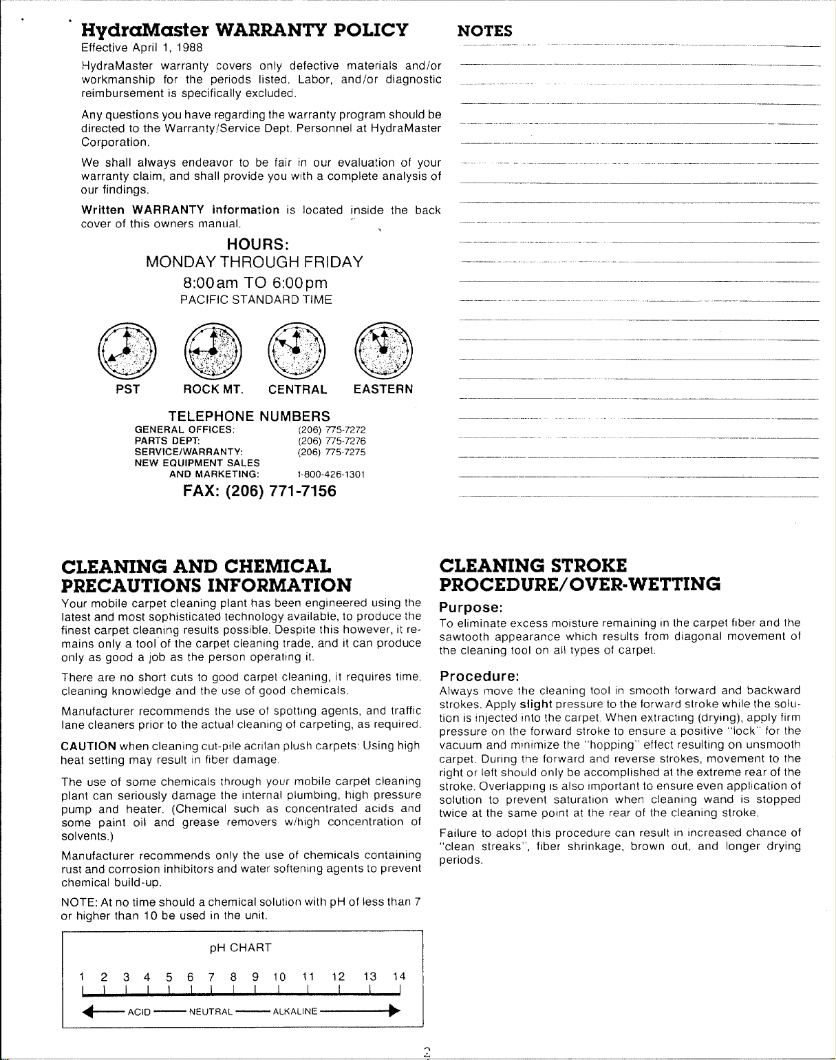
NOTE: At no time should a chemical solutlon with pH of less than 7
or higher than 10 be used In the unit.
CLEANING STROKE
PROCEDURE/OVER-WETTING
Purpose:
To ellminate excess moisture remaining In the carpet fiber and the
sawtooth appearance which results from diagonal movement of
the cleanlng tool on all types of carpet
Procedure:
Always move the cleaning iool In smooth forward and backward
strokes. Apply slight pressure to [he forward stroke while the solution is Injected Into the carpet When extracting (drying), apply firm
pressure on the forward stroke to ensure a positive “lock”’ for the
vacuum and mlntmize the “hopping” effect resulting on unsmooth
carpet. During the forward and reverse strokes, movement to the
right or left should only be accomplished at the extreme rear of the
stroke. Overlapping IS also Important to ensure even application of
solution to prevent saturation when cleanlng wand is stopped
twice at the same point al the rear of the cleaning stroke.
Failure to adopt this procedure can result In Increased chance of
“clean streaks”,
periods.
fiber shrinkage, brown out, and longer drying
pH CHART
1
234567891011 12
I I
1
+ ACID
I I I
I
— NEUTRAL
I I I I
‘ALKALINE~
I I
13 14
J
Page 5
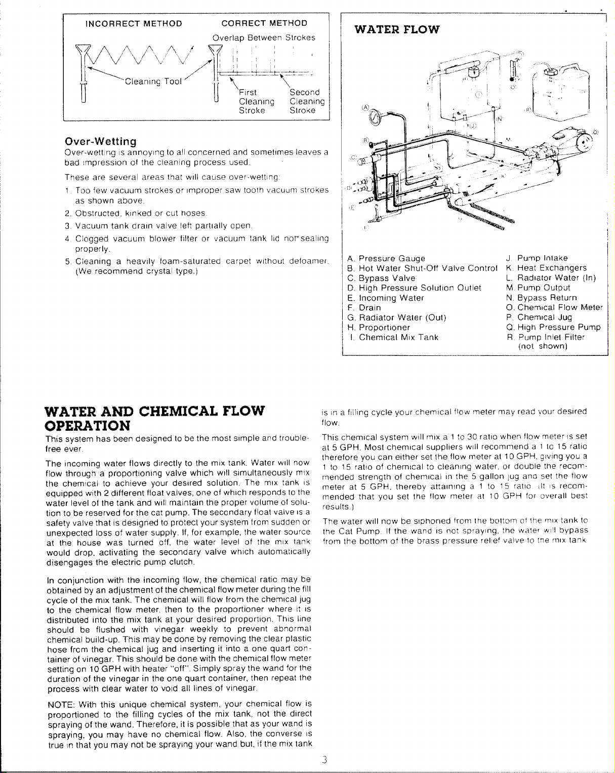
INCORRECT METHOD
—
CORRECT METHOD
Overlap Belween Strokes
~/l~/~b/+l,L,!’J>vlj /+: !; ‘; , ‘
,,/
‘1
T
,,
CLeaningTool’
II
Over-Wettinu
Over-wetting IS a;noylng to all concerned and sometimes leaves a
bad trnpresslon of the cleanlng process used
These are several areas that WIII cause over-wetting
1 Too few vacuum strokes or Improper saw Iooth vacuurv strokes
as shown above.
2. Obstructed. kinked or cut hoses
3. Vacuum tank drain valve left partlaiiy open
4 Clogged vacuum blower filter or vacuum tank lid nor seallng
properly.
5 Cleanlng a heavily foam-saturated carpet without defoamer
(We recommend crystal type.)
L.+-$_..;&y=..=...
1
First
I
Cleanlng Cleanlng
Stroke Stroke
Second
‘WATER FLCIVV
A. Pressure Gauge
B. Hot Water Shut-Off Valve Controf K Heat Exchangers
C. Bypass Valve
D. High Pressure Solutlon Outlet
E. fncomina Water
F. Drain G, Radiator Water (Out)
H. Proportloner
1, Chemical MIX Tank
J Pump Inlake
L. Radia[or Water (In)
M Pump Output
N. Bypass Return
0. Chemical Flow Meter
P Chemical Jug
Q. High Pressure Pump
R Pump Inlel Filter
(no{ shown)
--_-..l
,
WATER AND
CHEMICAL FLOW
OPERATION
This system has been designed to be the most simple and troublefree ever
The incoming water flows directly to the mlx tank. Water WIII now
flow through a proporhonlng valve which WIII simultaneously mlx
the chemical to achieve your desired solution. The mlx tank IS
equipped with 2 different float valves, one of which responds [o the
water level of the tank and WIII mainiain the proper volume of solution to be reserved for the cat pump. The secondary float valve IS a
safety valve that IS designed to protect your system from sudden or
unexpected loss of water supply. ff, for example, the water source
at the house was turned off, the water level of the mlx tank
would drop. activating the secondary valve which automatically
disengages the electric pump clutch.
In conjunction with the incoming flow, the chemical ratio may be
obtained by an adjustment of the chemical flow meter during the fill
cycle of the mix tank. The chemical will flow from the chemical Jug
to the chemical flow meter, then to the proportioner where It IS
distributed into the mix tank at your de.wred proportion. This line
should be flushed with vinegar weekly to prevent abnormal
chemical build-up. This may be done by removing the clear plastlc
hose from the chemical jug and inserting it into a one quart container of vinegar. This should be done with the chemical flow meter
setting on 10 GPH with heater “off” Simply spray the wand for the
duration of the vinegar in the one quart container, then repeat the
process with clear water to void all lines of vinegar.
NOTE: With this unique chemical system, your chemical flow is
proportioned to the filling cycles of the mix tank, not the direct
spraying of the wand. Therefore, it is possible that as your wand IS
spraying, you may have no chemical flow. Also, the converse IS
true In that you may not be spraying your wand but, if the mlx tank
IS In a ftlhng cycle your chem{cal flow rmeter may read vour desired
flow
This chemical system WIII mlx a 1 1030 ratio when flow meter IS sei
at 5 GPH. Most chemical suppllers WIII recommend a 1 10 15 ratio
therefore you can either set the flow meter at 10 GPH, glwng you a
1 to 15 rat!o of chemical to cleaning water, or double the recoin.
mended strength of chemical in the 5 gallon jug ano set the flow
meter at 5 GPH, thereby attalnlng a 1 to 15 ral{o If IS lecom mended that you set the flow meter al 10 GPH for overall best
results. )
The water WIII now be siphoned frorr lhe bottoln ot lhe m!x tank to
the Cal Pump If the wand IS not spraying, the water WIII bypass
from the bottom of the brass pressure rellef valve to tne mix tank
3
Page 6
.
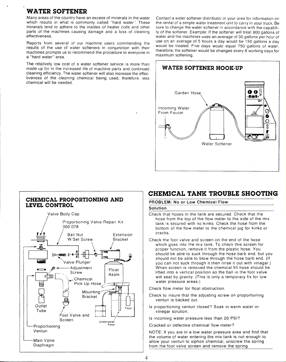
WATER SOFTENER
Many areas of the country have an excess of minerals in the water
which results in what is commonly called “hard water”. These
minerals tend to adhere to the insides of heater coils and other
parts of the machines causing damage and a loss of cleaning
effectiveness,
Reports from several of our machine users commending the
results of the use of water softeners in conjunction with their
machines prompts us to recommend the procedure to everyone In
a “hard water” area,
The relatively low cost of a water softener service is more than
made up for in the increased life of machine parts and cont[nued
cleaning efficiency. The water softener will also increase the effectiveness of the cleaning chemical being used, therefore, less
chemical will be needed,
.
Contact a water softener distributor in your area for information on
the rental of a simple water treatment unit to carry in your truck. Be
sure to change the water softener in accordance with the capability of the softener, Example: If the softener will treat 900 gallons of
water and the machines uses an average of 30 gallons per hour of
use on an average of 5 hours a day would be 150 gallons a day
would be treated, Five days would equal 750 gallons of water,
therefore, the softener would be changed every 6 working days for
maximum softening,
WATER SOFTENER HOOK-UP
CHEMICAL PROPORTIONING AND
LEVEL CONTROL
Valve Body Cap
/
/
f;?
Proportlontng Valve Repair Kit
000078
Ball Nut
W ‘Set Screw
-’/
–C=U*::;
+7J
i
Outlet
Tube
L
Proportioning
Venturi
—Main Valve
Diaphragm
—
+------Adjustment
Screw
\,
-Chemical
“ck ‘p ‘ose<-”
Mounting
Bracket
8
f
Foot Valve and ‘;
Screen
—.
m
Underwater
Float
Assm.
~
Feed
Extension
,....- .
USl
L/
/
Float
Water Softener
CHEMICAL TANK TROUBLE SHOOTING
PROBLEM: No or Low Chemical Flow
Solution
Check that hoses in the tank are secured. Check that the
hose from the top of the flow meter to the side of the mix
tank IS secured with no kinks. Check the hose from the
bottom of the flow meter to the chemical jug for kinks or
cracks.
Check the foot valve and screen on the end of the hose
which goes into the mix tank. To check this screen for
proper function, remove it from the plastic hose. You
should be able to suck through the hose barb end, but you
should not be able to blow through the hose barb end. (If
you can not suck through it then rinse It out with vinegar. )
When screen IS removed the chemical fill hose should be
lifted into a vertical position so the ball In the foot valve
will seat by gravity. (This is only a temporary fix for low
water pressure areas. )
Check flow meter for float obstruction.
Check to insure that the adjusting screw on proportioning
venturi is backed out.
Is proportioning venturi closed? Soak in warm water or
vinegar solution,
Is incoming water pressure less than 20 PSI?
Cracked or defective chemical flow meter?
NOTE: If you are in a low water pressure area and find that
the volume of water entering the mix tank is not enough to
allow your venturi to siphon chemical, unscrew the spring
from the foot valve screen and remove the spring,
4
Page 7
.
PRO EtLEM: Inability to Adjust Chemical with the Flow Meter
Solution
Debris lodged behind teflon seat In flow meter knob.
Teflon seat dismounting from flow meter knob.
PRQBLEM: Solution Reversing from Mix Tank to Chemical
Jug
Solution
Anti-siphon screen removed from chemical jug hos>,
Debrvs in anti-siphon screen,
PROBLEM: Mix Tank Overflows
solution
Float ball in mix tank hanging up (not moving freely)
Extension bracket plnchlng the float lever, restrlc!{ng full
act~on of the lever.
Plunger not seating properly on the valve. (Remove th6 2
screws which hold the extension assembly to [he valve
Do not lose or drop the screws. Remove the extension
assembly. Turn it upside down Inspect the plunger for
proper seattng. If there !s no debris obstructing the valve
or plunger, the plunger may be out of ad)ustmen[. To ad-
just, loosen the set screw on the ball nut and move the
ball toward the end of the rod 116’”. Retlghten set screw
Place extension assembly back Into posltlon Tighten the
two screws,
—.
..—
PROBLEM: Mix Tank Doesn’t Keep Up With Water Output
Solution
Check garden hose quick connect assembly screen
Check garden hose andor feed hose IP
kinks or blockage.
Float ball In mix tank hanging up (Not mo\lng treely, j
Extension bracket plnch[ng float lever, restricting full action of
lever
Valve plunger not opening fully To adjusl, remove the 2
screws which hold the extension assembly to the valve.
(Do not lose or drop the screws ) Remove lhe extension
assembly, turn It up side down To adjusl, loosen the set
screw on the ball nut Place vour Ihumb on the plunger
and press [t In 1 16” and sllde the oall nut w set screw
toward the plunger end 1 16’ Tghter Ihe set screw
Place ihe exten ;Iofl assembly back nto pos{tlon If the
tank starts to o\erflll, the ball nut m to close to Ihe valve
plunger and should be Imoved back away from the valve
plunger slightly.
PROBLEM: Pump Pulsates When The Tank Is in a Fill Mode
Solution
Check that the hose which goes from- [he grav”plast!c venturi
to the bottom of the tank IS not drecled toward Ihe Cat
pump pick up port If It m a!rn II m ano[her drec[lon
!he mx tank for clog,
-----
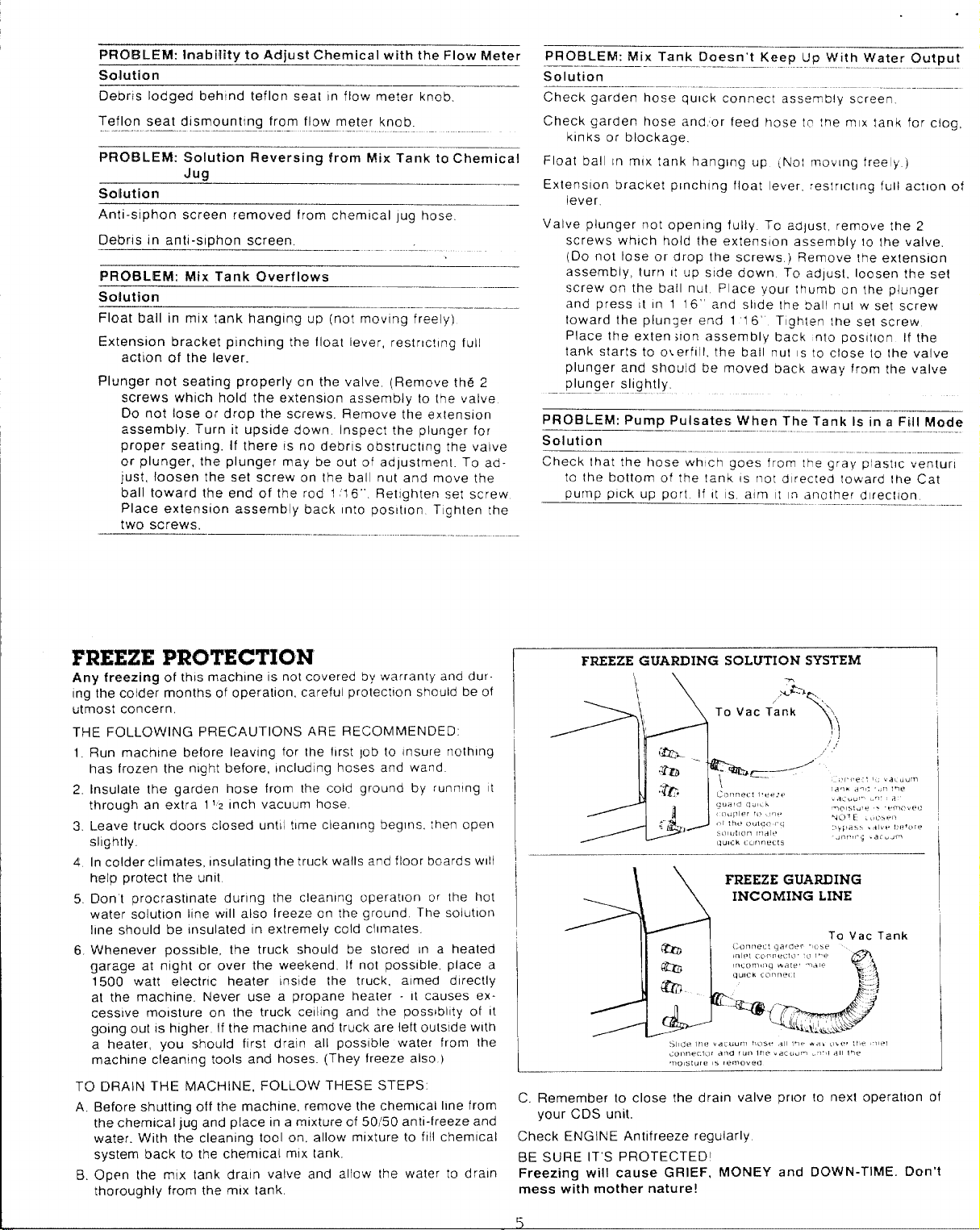
FREEZE PROI”ECTION
Any freezing of this machine IS not covered by warranty and dur-
ing the colder months of operation, careful protection should be of
utmost concern
THE FOLLOWING PRECAUTIONS ARE RECOMMENDED:
Run machine before Ieawng for the Ilrst job to Insure nothing
1
has frozen the night before, Including hoses and wand
Insulate the garden hose from the cold ground by running t
2
through an extra 11z Inch vacuum hose
3
Leave truck doors closed until time cleaning begins, [hen operl
shghtly,
4
In colder climates, Insulating the truck walls and floor boards WIII
hetp protect the unit
Don’t procrastinate during the cleaning operation or [he hot
5
water solutlon Ihne WIII also freeze on the ground The solutlon
Ilne should be insulated (n extremely cold clrmates.
Whenever possible, the truck should be stored In a heated
6
garage at mght or over the weekend. If not possible, place a
1500 watt electric heater tnslde the truck, aimed directly
at the machine. Never use a propane heater - It causes excessive moisture on the truck celllng and the poss~bllty of It
going out IS higher If the machine and truck are left outside with
a heater, you should first drain all possible water from the
machine cleaning tools and hoses. (They freeze also )
TO DRAIN THE MACHINE, FOLLOW THESE STEPS
A,B,Before shutting off the machine, remove the chemical Ilne from
the chemical jug and place in a mixture of 50/50 anti-freeze and
water. With the cleaning tool on, allow m!xture to fill chemical
system back to the chemical m{x tank.
Open the mix tank drain valve and allow the water to drain
thoroughly from the mlx tank.
C. Remember to close the drain valve prior lo next operation of
your CDS unit.
Check ENGINE Antifreeze regularly
BE SURE IT’S PROTECTED
Freezing will cause GRIEF,
mess with mother nature!
MONEY and DOWN-TIME. Don’t
5
Page 8
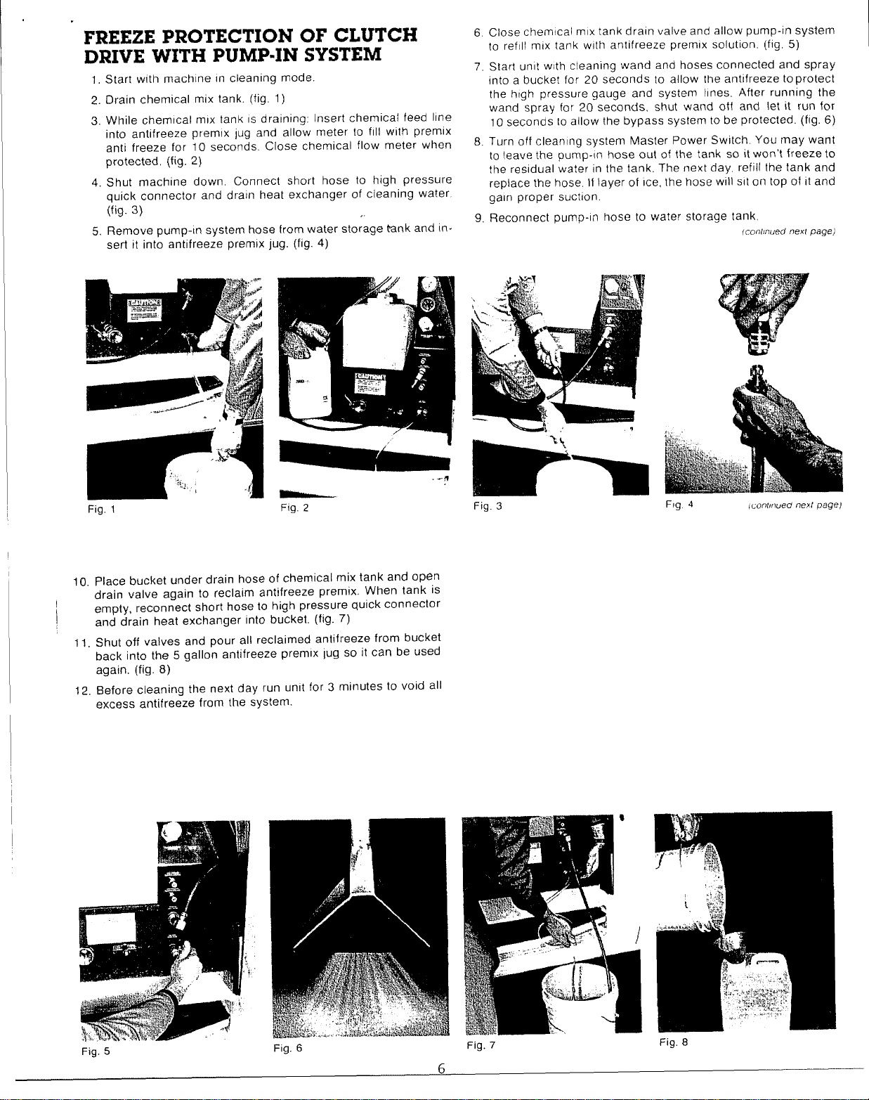
FREEZE PROTECTION OF CLUTCH
DRIVE WITH PUMP-IN SYSTEM
1.
Start with machine In cleaning mode.
Drain chemical mix tank. (fig. 1)
2.
While chemtcal mlx tank IS draining: Insert chemical feed Irne
3.
into antifreeze prem!x lug and allow meter to fill with premix
anti freeze for 10 seconds. Close chemical flow meter when
protected, (fig. 2)
4
Shut machine down Connect short hose to high pressure
quick connector and dratn heat exchanger of cleaning water.
(fig. 3)
Remove pump-in system hose from water storage tank and in-
5
sert it into antifreeze premix jug. (fig. 4)
/.
6
Close chemical mlx tank drain valve and allow pump-in system
IO refill mix tank wllh antifreeze premix solutlon. (fig, 5)
Start unit wtth cleaning wand and hoses connected and spray
7.
into a bucket for 20 seconds to allow the antifreeze toprotect
the high pressure gauge and system Ihnes. After running the
wand spray for 20 seconds, shut wand off and let it run for
10 seconds 10 allow the bypass system to be protected. (fig. 6)
8.
Turn off cleantng system Master Power Switch. You /may want
to leave the pump-in hose out of the tank so it won’t freeze to
the residual water in the tank. The next day, refill the tank and
replace the hose, If layer of Ice, the hose w!II slt on top of it and
gain proper suction.
9,
Reconnect pump-in hose to water storage tank
fcomwed nexr page)
Fig, 1 Fig. 2
10. Place bucket under drain hose of chemical mix tank and open
drain valve again to reclaim antifreeze premix. When tank is
I
empty, reconnect short hose to high pressure quick connector
and drain heat exchanger into bucket, (fig. 7)
11, Shut off valves and pour all reclaimed antifreeze from bucket
back into the 5 gallon antifreeze premix lug so it can be used
again. (fig. 8)
12. Before cleaning the next day run unit for 3 minutes to void all
excess antifreeze from the system.
Fig. 3
Flg
4
tmnhwed nexl
page)
Fig. 5
Fig. 6
Fig. 7
Fig. 8
Page 9
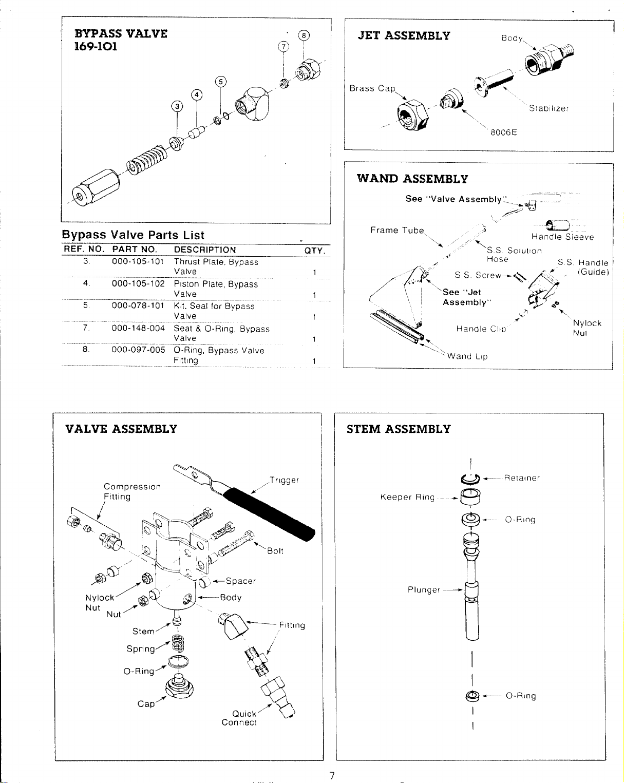
BYPASS VALVE
7
M9-lc31
Bypass Valve Parts List
R~F. NO. PART NO.
3.
000-105-101 Thrust Plate, Bypass
4.
000-105-102 P[ston Plate, Bypass
—.
5
000-078-101 Kli. Seal for 8vt)ass
DESCRIPTION
Valve
Valve
———.
“Q
Q;
1,
.’
5
AsiJ
bl!fjJ-
/’SF’
QTY.
1
1
JET ASSEMBLY
Brass Cap.
k
..- ‘ ‘
@
WAND ASSEMBLY
See “Valve Assembly’.”.
Frame Tube,
“x ‘
Bodv
\
‘8006E
Stablllzer
>~~ ‘
“ad
Handle Sleeve
,3
“S. S Solu[lon
Hose
S S Handle
VALVE ASSEMBLY
-..,.,.,
STEM ASSEMBLY
Keeper Ring +
Plunger --
‘Wand Ltp
I
Q+- Retaner
q3
I
Quick’
Connect
v
I
@—-
I
I
O-R,ng
Page 10
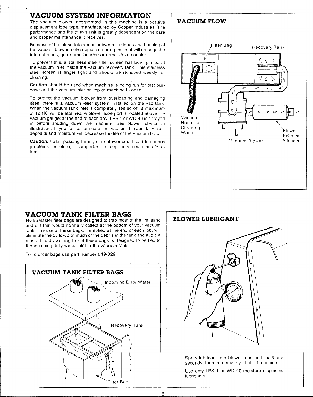
VACUUM SYSTEM INFORMATION
%3LfGap
8
The vacuum blower incorporated in this machine is a positive
displacement lobe type, manufactured by Cooper Industries. The
performance and life of this unit is greatly dependent on the care
and proper maintenance it receives.
Because of the close tolerances between the lobes and housing of
the vacuum blower, solid objects entering the inlet will damage the
internal lobes, gears and bearing or direct drive coupler.
To prevent this, a stainless steel filter screen has been placed at
the vacuum inlet inside the vacuum recovery tank. This stainless
steel screen is finger tight and should be removed weekly for
cleaning.
Caution should be used when machine is being run for test purpose and the vacuum inlet on top of machine is open,
To protect the vacuum blower from overloading and damaging
itself, there is a vacuum relief system installed on the vac tank.
When the vacuum tank inlet is completely sealed off, a maximum
of 12 HG will be attained. A blower lube port is located above the
vacuum gauge; at the end of each day, LPS 1 or WD-40 is sprayed
in before shutting down the machine. See blower lubrication
illustration. If you fail to lubricate the vacuum blower daily, rust
deposits and moisture will decrease the life of the vacuum blower,
Caution: Foam passing through the blower could lead to serious
problems, therefore, it is Important to keep the vacuum tank foam
free.
,.
VACUUM FLOW
Filter Bag
r-T-7%-----=
FlrFTlll
“-’-z”i#
Vacuum
Hose To
Cleamng
Wand
w
Recovery Tank
\
Blower
Vacuum Blower Silencer
Exhaust
VACUUM TANK FILTER BAGS
HydraMaster filter bags are designed to trap most of the lint, sand
and dirt that would normally collect at the bottom of your vacuum
tank, The use of these bags, if emptied at the end of each job, will
eliminate the build-up of much of the debris in the tank and avoid a
mess The drawstring top of these bags is designed to be tied to
the incoming dirty w~ter’inlet in the v~cuum tan~
To re-order bags use part number 049-029.
“ty Water
Tank
‘Filter Bag
BLOWER LUBRICANT
Spray lubricant into blower lube port for 3 to 5
seconds, then immediately shut off machine.
Use only LPS 1 or WD-40 moisture displacing
lubricants.
Page 11
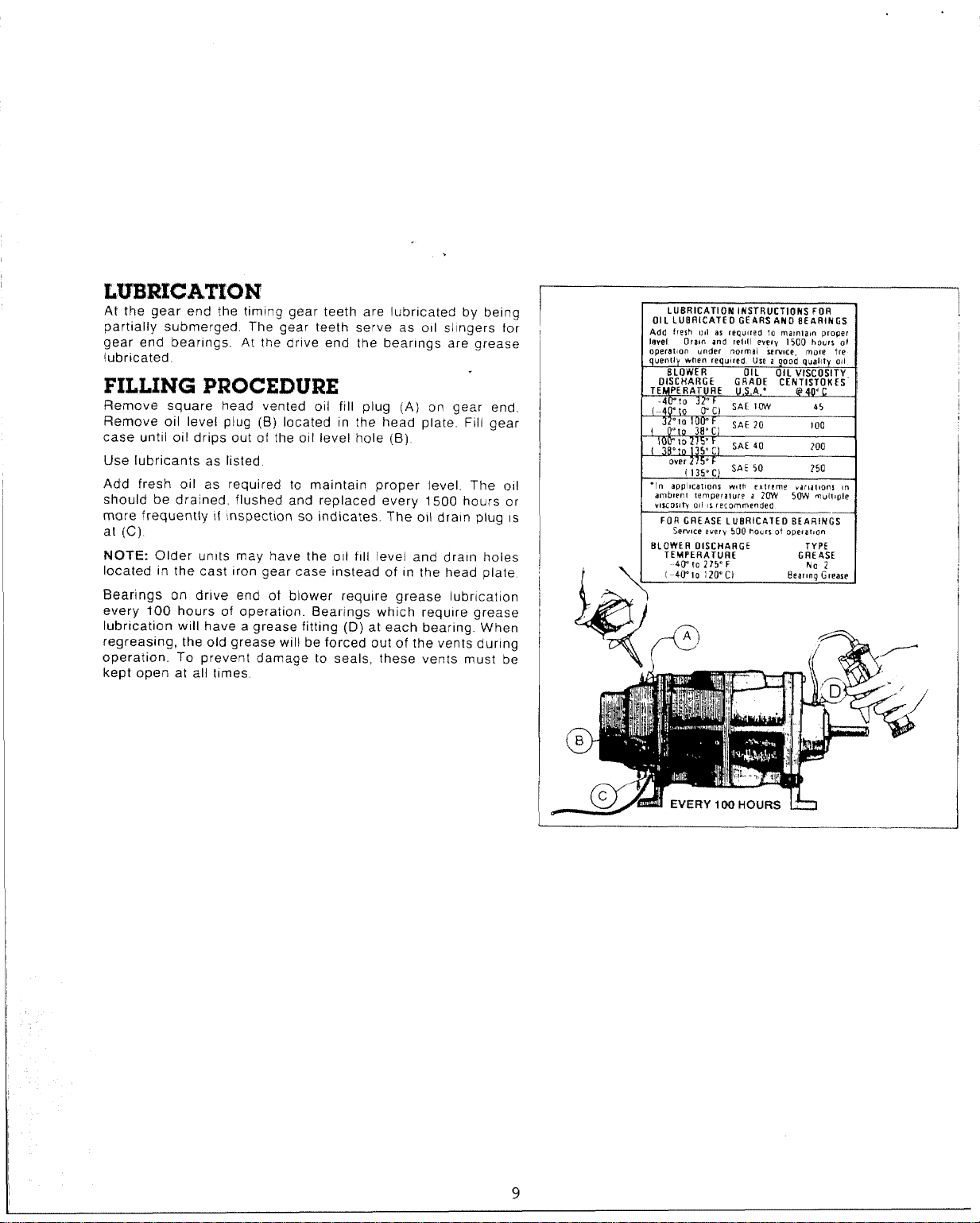
At the gear end the timing gear teeth are lubricated by being
partially submerged. The gear teeth serve as 011 sllngers for
gear end bearings. At the drive end the bearings are grease
lubricated,
FILLING PROCEDURE
Remove square head vented oil fill plug (A) on gear end.
Remove oil level plug (B) located in the head plate. Fill gear
case until oil drips out of the o(I level hole (B)
Use lubricants as listed
Add fresh oil as required to maintain proper level, The 011
should be drained, flushed and replaced every 1500 hours or
more frequently If Inspection so indicates. The oil drain plug IS
at (C),
NOTE: Older units may have the 011 fill level and drain holes
located in the cast Iron gear case instead of In the head plate
Bearings on drive end of blower require grease Iubr[catlon
every 100 hours of operation. Bearings which require grease
lubrication will have a grease fitting (D) at each bearing. When
regressing, the old grease will be forced out of the vents during
operation. To prevent damage to seals, these vents must be
kept open at all times.
I
Serwce every 500 ho. u of ope(af, on
-
I
9
Page 12

VACUUM BLOWER TROUBLE SHOOTING GUIDE
10
PROBLEM: Loss of Vacuum
Cause
Collapsed vacuum hose between b~wer and vacuum tank.
Clogged stainless steel filter.
Defect!ve vacuum tank seal.
Defective or ‘open’ vacuum tank dump valve.
Fractured weld on vacuum tank.
Collapsed or kinked vacuum hose.
Plugged vacuum hose.
Restriction in cleaning tool.
‘Worn end plates or lobes in vacuum blower.
_—— —
Loose drive shaft between clutch an~”blower.
PROBLEM: Blower is Seized
Cause
Rust.
Foreign rn”atter.
NOTE: The above mentioned, rust, foreign matter and seizing are often caused from foam traveling through the blower.
—
—
—-— ———- .-— ——___
.
Solution
Remove and replace hos~. NOTE: A special reinforced hose
is required for replacement.
Remove and clean or replace stainless steel filter.
Remove and replace vacuum tank seal.
Close valve.
Replace valve.
Re-weld as required or replace tank. Reshape hose if possible and/or eliminate kinks.
Remove obstruction by reversing the vac~um hose.
Remove obstruction.
Replace worn components. NOTE: Must be accomplished by
a qualified technician.
The set screws may come loo~e causing blower to stand still
while engine may be turning properly. NOTE: Unless the
blower is seized or making a knocking noise, your vacuum
loss is not caused by a bad blower.
Solution
Spray rust dissolving lubricant onto lobes to emulsify-rust and
attempt to rotate vacuum lobes.
Disassemble and remove foreign matter and repair as
required. NOTE: Disassembly must be accomplished by
qualified technician.
—-
PROBLEM: Noise in Vacuum Blower
Cause
Loose Direct Drive Coupler
Worn Gears.
Lack of Lubrication. NOTE:
resulted from lack of lubrication,
——————-.—.
Worn bearings.
Debris and/or foreign material build-up. NOTE: A stainless
steel filter is provided at vacuum inlet located in vacuum
tank,
Loose or missing mounting bolts.
Permanent damage may have
.- .,..
aolu~lon
Examine universal shaft for defects and” retlghten lock bolts.
Replace universal shaft,
Remove and replace gears. NOTE Replacerne”nt”o-f gears
must be accomplished by a quallfled technician.
Timing of vacuum blower has been changed due to worn
components. Replacement of components must be
accomplished by a qualified technican
“Lubricate as specified, See index, -- “-
Remove and replace bearings as required. Must be
accomplished by qualified technician,
Disassemble vacuum blower and remove fore~gn material.
NOTE: Disassembly should be accomplished by qualified
technician only. Replacement of worn parts is recom-
mended if this procedure is necessary.
Tighten or reinstall mounting bolts.
———
Page 13

11
.
VACUUM BLOWER WARRANTY
1.All Sutorbllt California Series ‘F’ blowers are covered by this warranty
2. Warranty period IS 24 months from date of shipment, or 18 months from date of mstalla!lon, whchever occurs first
3, Sutorbilt w(II replace or repa!r any unit covered by this warranty without regard for the cause of failure
4, Customers claiming relief under this warranty shall issue a Purchase Order to Sutorbllt for a replacement un{t
Factory Repair Center, as directed.
6. On receipt of the blower a credit memo WIII be Issued to offset the P.O. Issued per (4) above.
7. Replacement unit will be shipped to customer at Sutorbllt’s expense to any destination in the US or Canada.
8. SUTORBILT reserves the right to withdraw the Uncontested Warranty where evidence Indicates appllcallon outside the
manufacturer’s stated performance area, or where there IS ewdence of abuse
CONTACT tSUTORBil. T FOR THE LOCATIOIV OF THE
FACTORY AUTHORIZED SERVICE CENTER NEAREST YOU
SUTORHILT/l NDLt STRIAL MACHINERY
2966 E Vlctorla Street
44
SUTOFWILP
$CJU3F%EF$
El
Compton, CA 90224
(213) 639-7600
Telex 244337SUT
FAX. (213] 639-7632
i
—
Page 14

CAT PUMP DIMENSIONS
2.28
— (58) —
[“
5.14
(130.5
i_
3/8” NP7 OUTLET
\
(33)
7
5.73
[145.5]
4:
I
..—
SPECIFICATIONS
U.S. Measure
Volume . . . . . . . . . . . . ,.3.5G.PM.
Discharge Pressure . . ...1200 P.S.1,
Max. inlet Pressure .-8.5 to 40 P.S, I.
RPM, ..., , . . . ..1200 RPMoo RPM
Bore, ... ,. ..,. ,0.787”
I
I
L
Stroke ., . . . . . . . . . . . . . ...0.472”
Crankcase Capacity 100z,
Maximum Fluid Temperature, ..160°F
Inlet Ports(l)..........,,.. .l/2’’NPT
Discharge Ports (2) ., ,3/8” NPT
Pulley Mounting ... ,,. ,,. .. E!ther side
Shaft Diameter ..0.650”
Weight .,..,,., ... ..l2.llbs,
Dimensions
.10,77”
X 9.06” X 5.14
Metric Measure
13 L/M
85 BAR
-0.6to + 2.8 BAR
1200 RPM
20 mm
12mm
3L
71°C
1 2“NPT
3 8“ NPT
E!ther side
16.5 mm
5.5 kg
273.5 x230x 1305mm
I
1+----77(27325).5)
~3.94[loo]J
J
13
Page 15

C&l’ I?tmmsMQCM 2!?0
—
———-—. ——.——....—_—
CIFERATIJ)?G
CALITKJN: CAT PUMPS are poslt~ve displacement pumps.
Therefore, a properly designed pressure relief mechanism MUST
be Installed In the discharge piping. Failure to install’ such rellef
mecharwsm could result m personal lnlury or damage to the pump
or sys!em. CaI Pumps Corporation does not assume any Itab(llty or
responsibility for the operat]on of a customer’s
system.
Products described hereon are covered by one or more of
the foltowlng U.S. patents: 3558244, 3652188, 3809508.
nwmwcmtm
hlgll pressure
r “
IMPORTANT DRIVE INFORMATION
Pump speed and pump output In gallons per minute as tabulated IS
based upon a 1725 RPM drwe motor. Select motor pulley size and
provide GPM of the approximate pump output desired
Pump RPM and GPM ouiput are approximate values due to varla-
tmns In pulleys, belts and motors between manufacturers and a
& 5°0 pump output tolerance.
Horsepower figures shown are brake horsepower figures. For gas
engine requirements. follow engine manufacturer’s recommendations In general, use a gas engine w[th approximately double to
electrlc motor horsepower
..
● N V CAT PUMPS INTERNATIONAL S b ●
Hamonte,lraal 29
E 2CCQ A“twerP %lgwm uamv, b(,i? GU ‘? 60Y EnwlanG
Ph.”. [031 2377224 – Telex 33%47
● CATWMPS-AGO
.(: AT P>.MP5 .,. ,,11)~
>, S,$, ,on ,.c-,, .,a, [$~e~e $!.6,
P,””, r’,,, Z’T?,
I
,6!*, 0W398
HORSEPOWER REQUIREMENTS
PRESSURE
Psi Psl Uwng 1725 RPM Molor &
Flow
GF’M
35 13 19
30 11 37
2.5 9 14
DETERMINING
THE
DETERMINING
THE REQUIRED ti.P.
DETERMINING
MOTOR PULLEY SIZE
Psi
1000 1200 Sld Pump
800
8AR BAR
EAR
L[M
55
PUMP RPM,
Note Consul! .nq,. e man.lacl. rec when .W” G W. ., m.se, enq!. e
7a
24
21
17
85 00
29
25
21 858 25
Rated G PM = “Desired’ G PM
Raled R.P M
GPM
X PSI =
.. ——. . .
1460
Molor Pulley O 0 z Pump Pulley O D.
Pump R P M
MOTORPULLEY SIZE
Pulley O 0
RPM Pulley
1200
1029
‘Oeslred’” R P M
Eleclrlc Brake
H P Required
Motor R,P-M”
35
30
Standard Garden
Hose Screen W{th
Pump-In System
PUMP-IN
SYSTEM
FLOW
,/
(
@
(
Incoming Waler
Connection
‘“ \
Page 16

PISTON MODEL 290 Exploded View
65
PARTS LIST Model 290
ITEM PART NO.
1
20285 O-Ring (Buns-N)
2 44274
3 85680
4
44377
5 44374
8 43340
9
43339 Crankcase Cover
10 43987 Bubble Oil Gauge
11
——————
12 25625______ .__Q~a[n&uQ ___—
15
23170 O-Ri~ Drain Plug
92520 Sems Comb Head Screw
16 43804
17 14487
18 _
19
20
—–—?:.—.—-_..’ --- ,, ,V
24159 011Seal (Buns-N)
26536
___Q!X19, Oii seal Case
27950
21 — 92519
23
24
25
26
27
28
29
101799
101800 P[ston Rod
16948 Piston Pin
20017
25301 Oil Seal
25327 Barrier Slinger
25392
28771
30 29003
31
32
33
34
29614 Sleeve (29743 Unchromed)
26854 Seal Washer
28597
25128 Inlet Manifold
25635
DESCRIPTION
Crankcase
Stud (M8
X 82)
‘O-Ring, Oil Filler Cap
Oil Filler Cap
O-Rig, Crankcase Cover
(M6 x 20~
Crankshaft
——— —.—
R~arlnn
011Seal Case
Sems Comb, Head Screw
(M6
—.
X 16)
Connecting Rod
Seal Washer
O-Ring, Sleeve
O-Ring, Sleeve (Viton)
Back-Up Ring, Sleeve (Teflon)
Seal Retainer
‘Inlet Manifold-Stainless steel 1
QTY.
1
1
2
11
—
1
11
1
1
6
1
9“
.
2
22
8
33
3
3
3
3
3
3
3
3
3
3
1
ITEM PART NO.
35
30315
30325
38 ‘“ 27004
DESCRIPTION
Prrrrrm-A-Lube Seal
Prrrrrm-A-Lube SeaQV[to~
Inlet Valve
39 30543 Bac-CupPJston –
10. -....30.544‘-- __ Bs!sulmw:f Q!)
41
42
43
44
45
46-- 14158
47 101802
_ 48 ___23172 ____Q-R@,
49 21985
50
51 43442 Valve Spring Retainer
52 – 43360 _
--..8– L
—L_
58 25130 Shaft Protector
Electric Clutch Assembly
59
60
61
62 143-084 8-30 mm Socket Head Screw
63
64
43172 Cq (Vlton)
43474
27983
27002
27006
.Bac-Cup_Ass_~m~ lY.. __. -.
Piston S~r
Plston Retainer
Conical Washer-SS (M6)
27000 Nut-SS (M6)
Cotterpln
Cylinder (43834 Unch~
11377
O=Ring, Cylinder (Viton–~
cylinder (Buns.Np.J
Bat-Up Ring, Cylinder
24459 Discharge Manifold
25634
Discharge Manifoid-S.S.
Valve Spring
43723
43434
Valve
Discharge Valve Seat
81109 Hex Nut (M8)
101804 Hex Flange Nut (M8)
——
152-005 Tapered Sleeve
077-005
036-005
Key, Electric Clutch
6“ Electric Clutch
174-004 Flat Washer (5/16 US)
174-0 lF
Lock Washer (5/1 6 US)
QTY.
3
3
3
3
3
3
3
.-
3“
.-
3
3
3
3
.
—.
3
6
6
3
1
—.
1
3
3
3
————
3
2“
2-
1“
1
1“
1
1
——
1
1
Page 17

CAT PUMP TROUBLE SHOOTING GUIDE
PRC)HLEM: Low Pressure
—
Cause
Worn nozzle.
Belt Slippage.
Alr leak in lnlet”plumbing~ -
Pressure gauge inoperative or not registe; flg accurately
Relief valve stuck, partially plugged or imprope”~ly ”adjusted:
valve seat worn.
Inle; suction strainer clogged or Improper size
Worn p“lston assembly, Abrasives in pumped fluld or severe
cavitation. Inadequate water supply.
Fouled or dirty inlet or discharge valves.
Worn Inlet or discharge valves.
PROBLEM: PurnDs runs extremely rough, pressure very low
Inlet restrictions and~or air leaks. Damaged cup or stuck Inlet
or discharge valve.
Worn irilet manifold--seals.
.
..—. .—.
-.
.- —.-..—. .—.
.—
———.-
–x..
-. -.
Solution
—-. —.——---.——. —
Replace nozzle, of prope; size.
Tigh(en””or ~eplace; us-e correc~ belt,
Disassemble, reseal, and reassemble.
Check with new gauge: replace worn or damaged gauge,
P.N, 06090
Clean, and adiust rellef valve check for worn and dlrlv valve
seats. K\t available.
Clean. Use adequate stze Check more frequently
lnsta~ proper filter Suction at Inlet mamfold must be Iilmlted
to hftlng less than 20 feet of water or 85 PSI vacuum
Clean Inlet and discharge valve assemblies
Replace worn valves, valve seats.
Replace worn cup or cups clean out foreicjn mater la’. replace
worn valves,
Replace worn seals,
PHOBLEM: Cylinder O-rings blown next to discharge manifold
Cause
Pressures in excess of rated PST
Warped manifold.
PFIOHLEM: Leakage at the cylinder O-rings at the discharge manifold and black, powdery substance in the area of the
O-rinas
Cause
..—.. —..— ——————-
Loose cylinders, Cylinder motion caused by Improper Remove spacer shims on manifold s!uds Do not remove too
shimming of the discharge manifold. many shims or the ears of the manltold will be bowed
. .---- .. —... ....—— ..——..— ..—.
PROf3LEfd: Water leakage from under the inlet manifold
cause solution
Worn inlet manifold seals. Leaking sleeve O-ring. Install seals. If piston rod sleeves are scored, replace sleeves
—. .
PROBLEM: Oil leak between crankcase and pumping section
Cause Solution
Worn crankcase Riston rod seals. Replace crankcase piston rod seals
-.——.—-...——— —.
Excess oil from wicks.
PHQBLEM: Oil Ieakina in the area of Crankshaft
Cause
Worn crankshaft seal or improperly installed ott seal retainer
packing, seals.
.-——— —..——..— .
Solution
Check for plugged nozzle, closed valves or Improperly
adjusted by-pass valve
Replace manifold.
Solution
when the manifold IS retlghtened, causng looseness In
the center cyllnder
and sleeve O-rlrrgs
Reduce quantity of oil per oil!ng
Solution
Remove oil seal retainer and replace damaged gasket and/or
.
. .. . .. . . .
--.—.
. . . .
Page 18

CAT PUMP TROUBLE SHOOTING GUIDE (continued)
PROBLEM:
Cause
Bad bearing.
PROBLEM: Excessive play in the end of the crankshaft pulley
Cause
Worn main ball bearing from excessive tension on drive belt.
PRCIBLEM: Water in crankcase
Cause
May be caused by humid air condensing into water ~nside the
crankcase.
Leakage of manifold inlet seals and/or piston rod sleeve
O-ring.
Oil leaking in the area of Crankshaft
———.
———.-...———
—.—
—
_-—-—.——— ..——— —.
Solution
Replace bearing.
Solution
Replace ball bearing. Pr~perly tension belt.
Solution
Change oil at 3 month or 500 hour intervals using Cat Pump
Replace seals, sleeve and O-rings.
——..
Crankcase Oil (other approved oil every month or 200
hours) P, N.: 06100.
---.——
——.
—.
——-—
.
PROBLEM: Oil leaking from underside of crankcase
Cause
Worn crankcase piston rod seals, Replace seals, sleeve and O-rings.
PROBLEM: Oil leaking at the rear portion of the crankcase
Cause Solution
Damaged or improperly installed oil gauge or crankcase rear Replace oil gauge or cover O-ring, and dra!n plug O-ring.
cover O-ring, and drain plug O-ring.
PROBLEM: Oil leakage from drain plug
Cause Solution
Loose drain plug or worn drain plug O-ring Tighten dra~ plug or replace O-rin”~
PROBLEM: Loud knocking noise in pump
Cause
Pulley loose on crankshaft.
Broken or worn bearing.
PROBLEM: Frequent or premature failure of the inlet manifold seals
Cause
Scored rods or sleeves.
Over pressure to inlet manifold.
—
—. .—
—-
—-— .—— --——.——
————— ._
_— .
,
Solution
———— .—
Solution
Check key and tighten set screw.
Replace bearings.
Solution
Replace rods and sleeves.
Reduce inlet pressure per instructions.
.——-. —
.-
———
PROBLEM: Short cup life
Cause
Damaged or worn chrome plating of the cylinders.
Abrasive material in the fluid being pumped.
Excessive pressure and/or temperature of fluid being pumped.
Over pressure of pumps.
Running Pump dry.
Front edge of piston sharp.
Chrome plating of cylinders damaged causing excessive wear
of cups. May be caused by pumping acid solution,
PROBLEM: Strong surging at the inlet and low pressure on the discharge side
Cause
Foreign particles in the inlet or discharge valve or worn inlet
andlor discharge valves.
—.
Solution
Replace cylinders.
Install proper filtration on pump inlet plumbing.
Check pressures and fluid inlet temperature; be sure they
are within specified range.
Reduce pressure.
Do not run pump without water.
Replace with new piston.
Install new cups and cylinders, Pump only fluid compatible
with chrome.
Solution
Check for smooth lap surfaces on inlet and discharge valve
seats. Discharge valve seats and inlet valve seats may be
lapped on a very fine oil stone; damaged cups and
.lb
discharge valves cannot be lapped but must be replaced.
— --
.—
—z—
Page 19

GENERAL INFORMATION F(3R
CA’r Pmm REPAIR
,4s you remove your discharge manifold, there IS a set of 3 check
valves (which usually fall out during dis-assembly). If the surfaces
of these check valves are dirty, or show signs of chemical build-up,
[t IS probable that they would remain open causing pressure loss
or pulsallon. Upon Inspecting the valves, make sure that the teflon
buttons m the valve spring retainers are still Intacl. Also examine
the discharge manifold. Look for problems such as cracks,
chemical buildup or warpage due to freezing. If this discharge
manifold is warped,
result In loss of pressure
The Cat pump cups are often the source of pressure loss. Upon inspection they may appear melted or torn, but often they ~111look
good. Replace them anyway, There IS no sure method of visually
inspecting the cups. HydraMaster recommends changing cups
whether they look good or not.
Anytime your pump IS being dismantled, HydraMaster recommends replacement of all ‘o’ rings and seals. This is merely a convenience to the customer to make sure that the Cat pump IS In top
operating condition.
The prrm-a-lube seals located within the Intake manifold w(II allow
alr to enter [he pump If they are worn. Again, It IS dlfflcult to wsually
pinpoint a defective prrrm-a-lube seal. Replace them all
Wlthln the piston sleeve cyllnders [here are 6 ‘o’ rings that are
about ‘4 the size of a penny If these ‘o’ rings are bad, water WIII be
pumped back Into the oil If this has occurred the 011WIII raise In
level and appear milky. If you are unable to repair seals right away.
change oil frequently. Repair the pump as soon as possible so as
to not damage bearing or connecting rods.
Itwill cause the check valves to stick and WIII
Repalnng of Cat puITlps IS not d dlfflcu(t task However, before>
dlsassemblng make sure you have the proper parls required
1 - short (or hot) cup klt 3 - Prrrm-a-lube seals
6 - piston sleeve o rings
Read InstructIons [horoughly pr!or to dlsassemolv and follow
directions as stated 011 all seals thoroughly prior lo lnslallatlon
(Remember, a newly scarred seal IS no bet[er than one you just
took out. )
i bo(tle Cat 011
SWWICE KIT%
078-001 Cup Kit
3 cup
6 O-Ring, Cylinder
3 Cotterpln
1 InstructIon Sheet
1
Cup Inserter
078-003 Seal Kit
30431
Prrrrrm-A-Lube SeaI
3
Cotterpln
3
Abrasive Paper
2
Instruction Sheet
1
Sleeve and Seal Kit
Prrrrrm-A-Lube Seal
3
Barrier Sllnger
3
Cotterpin
3
3
Sleeve
6
Q-Ring, Sleeve
1
Instruction Sheet
078-006 Valve Kit
3
Valve Spring Retainer
3
Valve Spring
Valve
3
Valve Seat
3
3
O-Rtng, Cyllnder
1
Instruction Sheet
30860
Piston Kit
6
O-Ring, Cyllnder
3
Back-Up Ring, Cylinder
3
Bat-Cup Piston
3
Bat-Cup Ring
3
cup
Piston Spacer
3
Piston Retainer
3
3
Conical Washer (M6)
3
Nut (M6)
3
Cotterpln
3
Inlet Valves
1
Instruction Sheet
PUMPING SECTION CUTAWAY
P(slon Retainer
Cup Washer.
Cotter Pln
Nut
Ptston Spacer
.... E%SS%%SI
\\ \
—.
I
Cyllnder
!r‘\N 1 ‘1
I
J
.
dw-
I
~ U
i-
4
13ac-Cup
I;i
Bat-Cup Ring
.-
Pls[on Rod Sleeve
/
Page 20

SERVICING
DISASSEMBLY:
Remove the discharge manifold as described
1.
Grasp cyllnders by hand and with an up and down motion, pull
2,
cylinders from inlet manifold.
Remove cotterpln, nut and washer from piston rod.
3.
Next remove retainer
4.
Remove inlet valve.
5.
REASSEMBLY:
Examine inlet valve
1.
Reverse valve and sand inlet side of ’valv= using !240 g~it paper
for clean surface or replace if evidence of excessive Wear. Slip
onto rod.
Examine piston seating surfaces and sand clean on flat surface
2.
using 240 grit paper. If extreme pitting or sharp edges, replace
piston,
Examine cup for wear, cracking, tearing or separation from the
3.
piston. If worn replace and lubricate before installing on pi}ton.
THE PUMPING SECTION
spacer and piston/cup assembly,
surfaces for pitting, scale or grooves.
NOTE CUP
bat-cup ring (when used) onto ~ston. Push cup over inserter
and square with all surfaces. Faulty cup installation causes
premature cup failure.
Lubricate piston assembly and slip onto rod.
Next replace piston spacer and retainer on rod,
4,
Replace washer, thread on nut and torque per specification
5,
chart.
NOTE: Always replace with new Stainless Steel Cotterpin and
turn ends under.
Examine cylinder walls for scoring or etching which causes
6.
premature wear of cups and replace if worn.
7.
Lubricate cylinder and replace o-rings and/or back-up rings if
worn or damaged. Carefully slip cylinders over rod ends and
push into inlet manifold in their orlglnal position. (front to back)
Position discharge manifold onto pump, replace fasteners and
8.
torque per specification chart.
INSTALLATION: W!pe cup inserter with oii, SliD
SERVICING THE VALVE ASSEMBLIES
DISASSEMBLY:
1, Remove the fasteners securing the discharge manifold to the
crankcase of the pump.
2, Support the discharge manifold and tap from the backside and
a soft mallet to separate from the crankcase and gradually work
free from cylinders,
3. Valve assemblies will remain in the manifold, Pump models
with the o-ring groove on the outside of the valve seat
require the assistance of a reverse pliers to remove the
valve seat. The valve, spring and retainer will then fall out when
the manifold is inverted.
Pump models without the o-ring groove on the outside of the
valve seat permit the seat, valve, spring and retainer all to fall
out when manifold is inverted,
REASSEMBLY:
1. Replace retainers in manifold chambers,
2. Next insert spring into center of retainer,
3. Inspect the valves for wear, ridges or pitting and replace if
necessary,
NOTE: Seating side of flat valves may be lapped on flat sur-
face using 240 grit paper. Quiet valves due to their shape must
be repiaced.
Insert valve over spring with recessed (dish) side down.
4
Next examine the seating surface of the flat valve seats and lap
with 240 grit paper or replace if evidence of excessive wear,
Quiet valve seats should be replaced if worn, Lap new quiet
valve and seat to assure positive seal.
5. Some pump models have o-rings and back-up rings on the
valve seat. Examine and replace if worn. Always lubricate
o-rings for ease of installation and to avoid damaging
elastomers.
NOTE: First insta// o-ring in groove on seat (towards seating
surface), then back-up ring.
NOTE: Models without outer groove on seat require the o-ring
to be placed on lip of retainer.
6. Insert valve seats into manifold chambers.
7. Position manifold back onto pump.
NOTE: Lubricate o-rings on cylinder and exercise caution
when slipping manifold over cylinders to avoid damaging
cylinder o-rings.
8. Replace fasteners and torque per specification chart,
NOTE: Replace all original shims when used. When new
manifold is used reshim pump.
CAUTION: When starting the pump, check to see that there is
no cylinder motion as this will cause premature failure of the
cylinder o-rings, Center cylinder motion can be eliminated by
switching with one of the end cy/inders.
18
Page 21

UISASSEME3LY:
1, Remove discharge manifold and piston assembles as
descrtbed.
2. Remove inlet manifold containing seals.
3. Grasp sleeves and with a pulhng and twlstlng motion remove
the sleeves from the piston rod.
NOTE: Grasp sleeve !Jwth p//ers on/y if rep/acfrrg worn s/eeves,
as this procedure will mar the sleeves.
4, Next remove seal retainer
5. Remove and examine o-rings and; or back-up rings on piston
rod for wear and reolace.
REASSEMBLY:
1. Lubricate new o-rings and/or back-up rings and slip onto ptston
rod. Install the first o-ring in the groove on the piston rod. Next
position back-up ring against the shoulder In front of the first
o-ring. Then Install the second o-ring. Exercise caution as you
slip the o-rtng over the thread end of the piston rod.
2, Examtne sleeves for scoring or etching and replace. Immerse
sleeves in oil and carefully twist and push sleeve onto rod
(machined counter bore end first).
3. Next mstail seal retainers. If wicks are used, replace wicks,
thoroughly saturate with oil, place In seal retainer and install
retainer.
4. Place inlet manifold on pair of clearance blocks wlfh crankcase
side down and drive out old seals
5. Invert inlet manifold with crankcase s/de up and Install new
seals. Lubricate circumference of seal and Install Prrrrrm-A -
Lube seal with garder spring down. II using blue dot seal blue
dot should be facing up when Installed
6
Slip lubricated seal Inserters onto plslon rod ends, posmon relet
manifold onto pump and remove seal Inserters
NOTE: Replace orfg~nal 7uan//ly washers on
rep(acmg fnler
NOTE: Some models secure /n/et manifold 10 cfan~case
Replace fasteners and
Reassemble piston assembles and discharge man{fold as
7
descr[bed
marllfold
lorr?ue per spec~f)cat~on chart
s(tJds Oefore
SERVICING CRANKCASE SECTION
1. While Inlet manifold. sleeves and seal retainers are removed,
examine crankcase seals for wear
2. Check oil level and for evidence of water In 011
3. Rotate crankshaft by hand to leel tor smooth bearing
movement.
4. Examine crankshaft 011 seal externally for drying, cracking or
leaking.
5. Consult factory or your local dlsirlbutor If crankcase serwce IS
ewdenced.
19
Page 22

CAT PUMP WARRANTY
This Cat Pump (“product”) IS warranted by the manufacturer to
be free from defects in workmanship and material for one year
from date of manufacturer’s shipment. This warranty is Iimlted
to repairing or replaclng products which manufacturer’s
investigation shows were defective at the time of shipment by
the manufacturer. All products subject to this warranty shall be
returned FOB. Cat Pumps Corp., Minneapolis, Minnesota
55430, U.S.A. for examination, repair or replacement.
The express warranty set forth herein is (n lieu of all other
warranties, express or implied, Including without limitation any
warranties of merchantability or fitness for a particular purpose
and all such warranties are hereby disclaimed and excluded by
the manufacturer. Repair or replacement of defective products
as provided above is the sole and exclusive remedy provided
hereunder and the manufacturer shall not be liable for any
further loss, damages or expenses, including incidental or consequential damages, directly or indirectly arising from the sale
or use of this product.
This warranty is subject to the following warranty conditions:
Important Conditions:
LUBRICATION - fill crankcase to the top of oil gauge window
per specifications with Cat Pump 011or equivalent SAE 40
weight hydraulic oil with antiwear and rust inhibitor addltlves.
Change Initial fill after 50 hour run-jr’ period. Change oil every
three months or at 500 hour intervals {hereafter, Prrrrrm-a-lube
seals need no lubrication. Blue dot seals and wicks must
receive three drops of Cat Pump 011per wick every 50 hours of
operation,
GOOD LUBRICATION IS THE EASIEST, MOST EFFICIENT
AND
MAINTENANCE.
RPM and PRESSURE - Pump operation must be within RPM
and pressure specifications. Pressure relief valve must be
Installed.
DO NOT PUMP ACIDS OR ABRASIVE FLUIDS with this unit.
Consult Cat Pumps for additional Information on questionable
fluids.
FREEZING CONDITIONS Pump must be protected from
freezing conditions.
LEAST EXPENSIVE OF
USE OF OTHER THAN CAT PUMP PARTS OR THEIR
EQUIVALENT VOIDS THE WARRANTY
PREVENTATIVE
20
Page 23

ELECYITW DIAGRAM
~------------------- ... ..... . . . . .
Temperature
I
Black
Blackr--
1’
! II
v
$?
.- -- - ________ —________ . . . . . .._ ,
L-----
J
Hlack
Vacuurr Tank KIII
- nla,“ —\+.+ . . ..-. -------- ..---—-–+
Tachometer
,’
Switch
\
\
,.
+-
Emergencv 13ra Ke
Swltctl
‘—–”
!----,
-~
ID
L.-,
lack.
1
(
L
r
Pump
Maa!?el
I
,
I ,“
1’
,/’vac””m
I
Soleno[d
Valve
G_.
–v.,,’,>.-——
w
Horn
Glulch
,1”
L.J
&
I:~:::
‘1
I_i.. h
TrI
!“ L, ”.,,,
Panek
1~
Green (Gray) (To Tach Sensor)
Brown (To Master Brake Cylmdect
Red’Wh!re (MIX Tank KII1 Sw,lch I
Red 14 [To fuse Lt. kl
~11111 I
ITO Vac Tank KIII Sw
Reo
“a’’ TOnOrn’-===i!L ~0,. .,,, ,T. rn. s.,,.,><,
-, -,---- --
J
1 .!1
)
/
–1
--”(Y
ELECTRICAL SYSTEM
The entire electrical system operates on 12 volts DC which is provialed by your truck’s battery. Battery levels are sustained by a
alternator designed within the eng[ne.
PFIQBLEM: Low Battery Voltage
Cause Solution
befect;ve battery, Remove- a“nd“replace; ““-”
C“orroded battery terminals. Clean terminals and” battery posls
Low battery fluid,
Loose” w~;tng-within electrical system. ““”
Electrical short in-”w~ring system” Examine electrical systerns for bare wres
Poor groun”d connection. Examine terminal arid remove corrosion If necessary
PROBLEM: lnoDerative Hour Meter
Cause Solution
Ti-me-ls ‘n~t advanctng correctly. Ver[fy 12 volts DC IS available at the hour meter with the
——..———
.
NOTE When new battery
before Installation or damage to the charging regulator may occur
Add water to appropriate” level.
Examine all Ierrnlnal connections and verify that Ihey are
secure.
ignition switch turned on. This can be accomplished wtth
a volt meter or a test lamp,
Remove and replace hour meter f 12 volts IS available.
A nylon gear within the clock may have been lammed due to
a sudden jolt of the machine or truck. You may try simply
tapping on the meter to try to free the nylon gear.
IS Installed insure t IS :, -orrt~ ch~rg~d
—
21
Page 24

MAINTENANCE PROCEDURES
To avoid costly repairs and down -ttme, It IS imperative
and practice good maintenance procedures from the
These procedures fall into daily, weekly, monthly and quarterly increments,
maintenance log for your convenience on page 39; it is recom-
mended that you affix a copy of the log on the vehicle door near
your unit for convenience and to serve as a maintenance reminder.
and are outlined below. We have prowded a
to develop
beginning.
.
Check lines for wear/chafing.
.
Check all nuts and bolts tfghten as needed.
●
Clean vacuum tank thoroughly with high pressure washer.
✎
Flush water and chemical system with 50/50 white vinegar
solution.
✎
Check engine RPM’s - ad]ust to 2600 RPM’s at the pump.
IMPORTANT: Record date and machine hours on maintenance
chart.
Daily
● Check engine oil level.
● Inspect garden hose screen - clean as needed.
● Visually inspect machine for loose wires, oil leaks, water leaks,
etc.
● Inspect recovery tank s/s filter and filter bag for tears, holes, etc.
- clean, repair or replace as needed.
● Lubricate blower with LPS-1 or WD-40 through blower Inlet.
Daily: Wipe machine down thoroughly with a damp cloth; flush
recovery tank out thoroughly. Empty filter bag and inspect for rips,
tears, etc. - replace as needed: remove, thoroughly clean qnd
reinstall stainless steel filter screen in recovery tank; Inspect and
clean vacuum slot on cleaning wand; check wand head for sharp
edges that could tear carpet - file down as needed; clean wand to
maintain original appearance; w{pe down vacuum and high
pressure hoses as needed - visually inspect for cuts, etc.
,
Weekly
● Check engine air cleaner filter - clean as necessary.
“ Check high pressure pump oil - add as necessary.
● Check pump drive belt for wear - tighten as needed.
● Check pump pulleys - tighten as needed.
Monthly
● Grease blower bearing fittings.
● Remove pressure bypass valve stem, grease cup and stem,
reinstall.
● Check water level in battery. Clean connections as needed.
lMPORTANfi
chart.
Record date and machine hours on maintenance
Quarterly
● Change 011 tn blower (see blower manual).
OVERALL CARE OF UNIT
MAINTAINING THE ORIGINAL APPEARANCE OF YOUR UNIT
IS IMPORTANT FOR TWO REASONS:
1
It represents a big dollar Investment for your cleaning business
and Its appearance should reflect that fact. A dirty machine is
not professional!
2
Maintenance, troubleshooting, and repair IS much easier to ac-
complish on a clean well maintained unlL Regular cleanlng of
the machine offers you an opportunity to visually inspect all
facets of the machine and spot potential problems before they
occur.
MAINTENANCE LOG
DAILY CLEANING & INSPECTION
Engine 011- check Clean
Garden hose screen - clean
Machine - qeneral Inspecflon
W& ~
VEEKLY SERVICE
25 B
25 P
25 DRIVE SHAFT SYSTEM
BELTS & PULLEYSch~
25
25 HIGH PRESSURE LINE!
25 NUTS & BO1-P “--’
25 BATTERY LE
25 V
25 WI HINti cne~
25 CHEMICAL L .-. -.. . . ..3-.
F
MONTHLY SERVICE
100 BY PASS VALVE grease cup & slem
‘~=:=’’====” ‘“--
QUARTERLY SERVICE (3 MONTHS)
BLOWER OIL change
300
300 ENGINE compression
300 SPARK PLUGS change
&x cWUvE
SliAFr me ~
YEARLY TRUCK MAINTENANCE
COMPLETE TUNE-UP
COOLING SYSTEM flush (add new anti-freeze)
TRANSMISSION FLUIO
.,
change
vac lank filter bag after every job
Blower tnlef spray wnh LPS 1 after lasf 10b
~ DATE HRS DATE H~s ! OATE H~s
I
DAIE HRS ~ DATE tiRS
1 1
---L–- ------- - ‘---- ‘- ---------- ------
—-
DATE H!+S I DATE tiRS
I
I
I
I
22
Page 25

mmmmw SLEEVES AND SEALS
WSAW3EMHLR
1, Remove
dmwikd.
2,
Remi.wei nletrrmnifold oantainlng seals. ‘
3. Grasp sleeves and wiitt a pulllng
ltm slsavea from me piwon red.
NOTE:
as thLs procedure wJI mer the sle%ves.
4. Naxl remove saai m{ainar.
5. Remove and exmnine
rod for wear and replace,
REASSEMBLY:
1. Lubrloate new o-rln~s and/or back-up rings and slip onto pkton
rod, hwteli lh@first o-ring in the groove on the pwton rod. Next
poailion backwp dng against the shoulder In front of the first
o-ring. ThM Instaii me second o-ring. Exercise caution as you
dip me o-ring over the thread end of the piston rod.
2, Exam Ins! slsraves for acafing or etching and repiace. immersa
sleeves In oii and Carefuliy twist
{machined coumterbore end first).
3. Nexl Install
thoroughly saturate with oil, piace In
retainer.
4. PIw Inlet manifold on psfr ckfclearmca btode with crenkcase
skiff
& hwert Inlet mw’tifold with crarfkcase side up and Install
sed6.
dlacharge manifold and piston assemblies as
and twlstlng motion remove
G<asp sleeve w/it? pfiers only ifreph?chq worn sleeves,
o-ring5 and/or back-up rings on piston
and push sieeve onto rod
aeai retainers. it wicks are used. rep iwa wlcks~
seai retainer and Install
down and drive oui old seala.
Lubricate clrcumference of awl and install Prrrrrm-A-
new
Lube seal with garder spring down. If using biuo dot aeai, biuo
dot should be faclrtg up when Irwtded.
& Slip Iubrfuited seal Inserter@ onto plsto n rod ends, powimn inlaf
manifold onto pump and remove aaai inmmtera.
NOTE: Replace orig!nal quantify washer% on sruda before
repiaclng inkt manifold.
NOTE: Sorr?e models secure Irrkt marrifotd to c{mrkcam$.
Repkce fasteners
7.
Rwmaamble piston assembllms and discharge manlfoid as
arrd torqm3 per speolflcafkwr MM,
deacrlbad.
SERVICING CRANKCASE SECTION
1, While inlet manifold, sleeves and seal rotalnerg are romovad,
examine
2, Check oil level and for evidanoe of water in oIL
3. Rolale crankshaft by hand 10 f@el for smooth bearins
movement.
4. Examine crankshaft cdl seal externally for drying, cracking or
leaking.
5. Consuff factory or your local distributor if crankcase e@rvIca 6a
evidenced.
crankcase seats for wear,
IMPORTANT;
ENMRGED VIEW
APPLY GREASE TO ZERK FITTINGS EVERY!$00OPERATINGHOURS.
LOCATION OF FllTINGS NOTED HERE.
I
I
23
Page 26

‘--
‘-
,
WARWNTY INFORMATION
To avoid misunderstandings which might occur between mac~ine
owners and manufacturer, we are Iistlng causes of component
failure that specifically voids warranty coverage. Such causes as
listed below shall constitute abuse or neglect.
BLOWER: Failure to lubricate impellers daily with LPS-1 or
WD-40 lubricant. Failure to lubricate bearings. Failure to maintain
proper oil levels in the blower. Fa!lure to use the correct oil grade
and viscosity as recommended. Failure to properly maintain
blower safeguard systems such as waste tank filter screen,
vacuum safety relief valve in vacuum tank lid and waste tank
automatic shut-off system. Allowing foam to pass through blower.
HIGH PRESSURE WATER PUMP: Operation of pump at pressure
over 1200 PSI. Failure to maintain proper oil level as recommended. Failure to change oil in pump at recommended intervals.
Failure to protect pump against freezing. Failure to maintain pump
protection shut-off system. Failure to use water softener in hard
water areas. Use of improper chemicals.
VAC TANK: Failure to properly malntaln filtering devices in tank.
Failure to clean tank as recommended by manufacturer. Failure to
maintain vacuum safety release in tank. Use of improper
chemicals.
CHEMICAL PROPORTIONER: Use of improper chemical. Failure
to use water softener in hard water area. Operating machine
without proper chemical filter screen, Failure to protect against
freezing,
CONTROL PANEL: Failure to protect flow meter and water
pressure gauge against freezing.
VACUUM AND SOLUTION HOSES: Failure to protect hoses
against freezing. Failure to protect hoses against burns from
engine/blower exhaust. Damage to hoses from being run over by
vehicles. Kinking or cracking from failure to store or unroll hoses
correctly, Normal wear and ~ear from everyday use,
CLEANING WAND: Failure to protect against freezing. Obvious
physical abuse of wand.
WARRANTY PROCEDURE
Warranty coverage is available to you ONLY through HydraMaster
Corporation, 20309 64th Ave. West, Lynnwood, Washington
98036. When warranty parts are needed, write l-lydraMaster
Warranty Dept. at the above address, or call the Warranty/
Service Dept. at (206) 775-7275. No collect calls will be ac-
cepted. Hours of Warranty/Service Dept. are 8:00 am to 6:00
pm Pacific Time.
IMPORTANT
HydraMaster’s warranty policy provides replacement parts without
charge for thirty (30) days to customers maintaining current
account status. An invo!ce dated thirty (30) days from date of
replacement parts shipment will be sent to the customer for the
amount of the parts sent. The customer’s faulty parts
returned for evaluation prior to the expiration of the thirty (30) day
period, Upon warranty approval, a credit will be issued the
customer for the replacement parts Invoice,
proval or failure to return the faulty parts within the thirty (30)
day period allowed will result in the customer being charged
for the replacement parts sent.
Warranty disap-
must be
24
Page 27

GOLDEN GUARANTEP
LIMITED
WARRANTY PLAN

c
‘::
- ,.
,7 .?
1. L,
. . ..,
,
,..
B
—
v
L
d
=-0
(3-/
I
@
u-
o/–-
w
C2
4
,,
\/
\/
Page 29

m
.-—.
...— —.
._—
c1
T
F
Ill
(-J
-P
\(n
{ :-
.
.
-.
c
—
Page 30

1.
HYDR/iMASTER
CORPORATION
20300 64th Avenue, West
l+mnwood, WA 96096
PRODUCT SUPPORT BULLETIN
TO: ALL HYI)RAMASTER DISTRIBUTORS
RE:
has encouraged the use of water softeners inconcert
with itsequipmenL With the intrcxiuclion of the3.5
AQUA CAT last year, the issue of wa~ersoftervm
has once again come up.
changers requires us to reiterate our position conczmingwatersoftemsand
tion of machine warranty claims due to hard water
and/or chemical
is a “hard water area map”. The map graphically
portrays the average hardness of water in each
region of the
excuse anyone living in a “soft water area” from
t Wt?fer Hardness
USE OF WATER SOFTENERS
,
For quite some time, HYDRAMASTER
Our increased usc of exhaust gas heat ex-
thesubsequen[ invalida-
deposits.
Included ineach HYDRAMASTER manual
United Stakx. This map does not
using water softeners if circumstances require il.
manual sLat&s:
e-xcess
common [y refered to as ‘hard waler’. 7h ese minerals
tend to adhere to the insides OJheater coils and &her
parfs oj(he machine causing
cleaning e~fectiveness... the relolively low COS[of a
wu[er softener service k more (} Janmade uj>for in [he
increased life of machine par[s and conlinued cleaning
eficien cy. ”
of minerals in the wtller which rcsuil in who [ LS
scaling procedures.
form
on [he inside of the machine may uuse damage. Any damages resulting from hard water or
chemieal deposits are considered abuse and/or ne-
I
DATE: 17 FEB ’92
PSB#: 9221
Under the heading of “wa(cr softeners”, the
‘(Many areas of fhe country have an
damage as well as Ims OJ
The manuals also have advice on de-
As sta Ledin the manual, any dcposi Lsthat
gled and will rml be cmvcred by ti
I
HYDRAMASER WARRANTY.
Avoid eos[ly repairs and
.downtimc byusingwhatevcrwa -
ter softening method that is
readily available. Also remember to follow-up [he de-scaling
reeommenda [ions that are shown
in your manual.
n 0-3’”
- 3W!-7
- 7-101/2
- 1012 and *“Q
for more information
please contact you r local
HYDRAMASTER
reprwentattve.
Page 31

20900
Lynnwood, WA 98096
04th AWUC, Went
.
.
HYDMMASTER
CORPORATION
PRODUCT SUPPORT 13LJLLET!N
TO: ALL HW2RAMASTEFF DISTRIBUTORS
HE:
TRANSMISSION OIL COOLERS
ON ALL CDS UNITS
,
DATE: 75 OCt 19%2
PSB #:
92101
P/N :000-078-080
FWDF?AM4STER is recommending the installation of transmission oil
coolers
in all
will
clutch. In locating the transmission oil cooler directly in
clutch, two functions ace accomplished: First, fh~ transmission cdl IS
cooled, and second, th~ fan clutch will be thermally activated and increase
the
onal[CDS installations. The transmission oil cooler will b6?inc[uded
CDS ‘finish kits’ from this date forward. The transmission oil coolers
be installed on the engine side of the radiator, directly in frant of the fan
front of the fan
airflow to the engine compartment.
Transmission oil coolers are available from the HYCIRAMASTER Parts
D~partment as a separate item under part number # OOCM78-CN30.
h
Page 32

20309 64th Avenue, Wcat
Lynnwood,
WA 98038
PRODUCT SUPPORT BULLETIN
.
HYDRA_iW2iSTER
CORPORATION
,
TO:
RE:
CHEVROLET CARGO VANS FOR 1993 HAVE A NEW ROUTING FOR THEIR BRAKE
LINES. THEY NOW TRAVEL DIRECTLY OVER
CAUTION IS REQUIRED
GER SIDE OF THE BLOWER FRAME. THE BRAKE
OF THE
LINES IN
THE BLOWER MOUNTING BOLT
ALL HYDRAMASTEF CDS INSTALLERS
’93 CHEV BRAKE LINES
WHEN DRILLING THE MOUNTING HOLE ON THE PASSEN-
WAY BY UNBOLTING TWO (2) MOUNTING BRACKETS THAT HOLD THE
POSITION.
.
TOP OF THE TRANSMISSION.
LINES CAN BE LOWERED OUT
FOR THIS FOOT SHOULD GO IN FROM THE
DATE: 27 OCT 1992
PSB #:
92102
BOTTOM, THEN RE-AITACH THE BRAKE LINES.
\
Page 33

L
4
.
HYDMMASTER
CORPOR4TIC)N
2090!3 64th Avenue, W-t
Lymwaod, WA 98096
P
PRODUCT SUPPORT BULLETIN
TO:
RE:
IMPORTANT
During
tunity to rwnind all HYDRAMASTER CDS Equipment users to make sure to check and
Iubricatethe fittings on the universal joints that are connected to the shafts
the blower ta ttm CDS clutch unit
ALL HYDJ7AMASTER DISTRIBUTORS
DRIVE SHAFT LUBRICATION
th@ unseasonably cold weather, HYDF3AMASTER would like to take the oppor-
DATE: 13 JAN I$W3
Pst3 #:
930101
that attach
Ideally, lubrication should be scheduled every
/-
APPLY GREASE TO ZERK FI’lllNGS EVERY 500 OPERATlF4G HOURS.
LOCATION OF FITTINGS NOTED HERE.
5(KI hours with #2 Bearing Grease.
\
Page 34

.*
HYDRAMASTER
CORPORATION
20S09 64th Avenue, West
Lynnwood, WA 98036
EFFECTIVE
PRODUCT’ SJJPPORT BULLETIN
TO: ALL HYL?RAMASTEW DISTRIBUTORS
RE:
As a result of improved performance, it has been decided to inhance the
grounding circuit by the addition of the following:
GROUNDING OF CDS UNITS’
#10 AWG wire to run from the engine block to the blower frame.
Then from the frame to the mix tank ground lug. Then to the neg-
ative terminal of the temperature gauge located in the instrument
panel. The upgrade will require 12’ of #10 AWG wire.
IMMEDIATELY:
DATE: 26 JAN 1993
PSB k
93013
(Route wire and attach
per iiiustration)
143-oo2 BOLT
094-007 NUT
174-017 WM$H33
17a-o14
GROUND WIRE
TO GA*E
4
WIRE
INE
TO MIX TANK
w
BLOWER FRAME
MOUNTING LEG
Page 35

21X309 t34tlI Avenue, West
~~91WOOC!,
WA 98096
FJR(XMJCT SUPPORT BULLETIN
HYDRziJkZASTER
CORPORATION
-m:
RE:
(
ALL HYDRAMASTEFP DISTRIBUTORS DATE: 4 APR 1!3$43
New CDS Van Cooling
P/N: 000-078-083
Kits - PSB #: 930401
HYDRAMASTEP has engineered a CDS Coo[ing Kit specifically designed to
move cooling air in and around
possibility of over-heating during operation.
The blower motor is secured to the frame of the vehicle with the hoses routed into
and around the engine compartment, A starter blanket is also included to insulate
the starter motor from excess heat.
For more details, please contact the HYDRAMASTEFF’ Service Department at:
the engine compartment thus reducing the
A/C: 206-775-7275
 Loading...