

Page 1
Clutch Drive System
4.8 / 4.6 Owner’s Manual
HydraMaster North America, Inc. - 11015 47th Avenue West,
Mukilteo, Washington 98275
Copyright 2009 HydraMaster North America, Inc.
MAN-33149 Rev. 0
(182-038-D)
No part of this manual may be reproduced or used in any form or by any means (i.e. graphic, electronic, photocopying
or electronic retrieval systems) without the express written permission of
All rights reserved.
Revised July 10, 2009
HydraMaster North America, Inc.
Page 2

Table of Contents
GENERAL INFORMATION ........................................................................... SECTION 1
Contact Information ........................................................................... 1-2
Warnings, Cautions and Notices ....................................................... 1-3
Machine Specications ...................................................................... 1-6
Responsibilities .................................................................................. 1-8
Purchaser’s Responsibility ................................................................ 1-8
Sales Representative’s Responsibility ............................................... 1-8
Local Water Precautions .................................................................... 1-9
Hard Water Advisory .......................................................................... 1-9
Hard Water Area Map ........................................................................ 1-10
Water Softener ................................................................................... 1-11
Waste Water Disposal Advisory ......................................................... 1-12
CHEMICALS AND CLEANING .................................................................... SECTION 2
Cleaning Precautions......................................................................... 2-2
Cleaning Stroke Procedure................................................................ 2-2
Overwetting........................................................................................ 2-3
OPERATING INSTRUCTIONS ..................................................................... SECTION 3
Before Operating the CDS ................................................................. 3-1
CDS Start Up ..................................................................................... 3-2
CDS Flood Restoration Work ............................................................ 3-2
CDS Shut Down................................................................................. 3-3
3 Speed Throttle Control Function ..................................................... 3-4
FREEZE GUARD ......................................................................................... SECTION 4
Draining the CDS ............................................................................... 4-2
Freeze Protecting Pump-In System ................................................... 4-3
WATER AND CHEMICAL SYSTEM ............................................................. SECTION 5
Water and Chemical Flow Operation ................................................. 5-1
Chemical System Maintenance ......................................................... 5-2
Chemical System Troubleshooting .................................................... 5-3
1.0. System will not prime ........................................................... 5-3
2.0. Chemical ow is unstable or low .......................................... 5-3
3.0. Chemical jug lls with water ................................................. 5-4
i - CDS 4.8 / 4.6 Owner’s Manual
Page 3

WATER PUMP MAINTENANCE .................................................................. SECTION 6
Daily Maintenance ............................................................................. 6-1
Periodic Maintenance ........................................................................ 6-2
Water Pump Troubleshooting ............................................................ 6-3
1.0.Will not come up to normal cleaning pressure ...................... 6-3
2.0. No pressure reading on PSI gauge ...................................... 6-3
3.0. PSI gauge reads normal; low pressure from tool/wand ....... 6-4
4.0. Pressure pulsation ............................................................... 6-4
5.0.Water box empty or lls slowly .............................................. 6-4
6.0. Water box overows ............................................................. 6-5
ASSEMBLIES AND PARTS LISTS ............................................................... SECTION 7
CDS Machine Assembly Parts List .................................................... 7-3
CDS Recovery Tank Assembly Parts List .......................................... 7-6
CDS Recovery Tank Cover Assembly Parts List ............................... 7-7
CDS Instrument Panel Assembly Parts List....................................... 7-10
CDS Hi-PSI Manifold Assembly Parts List ......................................... 7-11
CDS By-Pass Valve Assembly Parts List ........................................... 7-12
CDS 4.8 Pump and Blower Assembly Parts List ............................... 7-15
CDS 4.6 Pump and Blower Assembly Parts List ............................... 7-18
CDS Pump Assembly Parts List ........................................................ 7-20
CDS DuraFlow Automatic Pump Out (APO) Assembly Parts List ..... 7-22
CDS Dash Box Assembly Parts List .................................................. 7-25
CDS Dash Panel Assembly Parts List ............................................... 7-27
CDS Water Box Assembly Parts List ................................................. 7-30
Diffuser Filter Assembly Parts List ..................................................... 7-31
CDS Vacuum Relief Valve Assembly Parts List ................................. 7-32
CDS Front End 2003 - 2009 GM Assembly Parts List ....................... 7-34
Horizontal Pump In Tank Assembly Parts List ................................... 7-37
Free Standing Tray Assembly Parts List ............................................ 7-38
85-Gallon Rotomolded Fresh Water Tank Assembly Parts List ......... 7-42
85-Gallon Rotomolded Fresh Water Tank
with Reel Assembly Parts List ................................................. 7-43
125-Gallon HydraCradle Tank Assembly Parts List * ......................... 7-47
CDS Pass Through Assembly Parts List ........................................... 7-48
CDS Standard Heat Exchanger Assembly Parts List ........................ 7-49
CDS Heat Exchanger Assembly Parts List ........................................ 7-50
CDS Salsa 2005 - 2009 Assembly Parts List..................................... 7-51
Ford Hush Kit Mufer Assembly Parts List - 4.8 ............................... 7-52
Chevy Hush Kit Mufer Assembly Parts List - 4.8 ............................ 7-53
Silencer Assembly Parts List - 4.6 ..................................................... 7-54
CDS Belts Parts List .......................................................................... 7-55
Cleaning Wand Valve Assembly Parts List ........................................ 7-56
CDS 4.8 / 4.6 Owner’s Manual - ii
Page 4

Cleaning Wand Solution Valve Assembly Parts List .......................... 7-57
Cleaning Wand Valve Stem Assembly Parts List ............................... 7-58
Hydra Hoe Wand Assembly Parts List ............................................... 7-60
GM Cowling Assembly, 2003 – 2009 Parts List (P/N 601-020-008) .. 7-61
2009 Ford Cowling Assembly Parts List (P/N 601-020-001) ............. 7-61
CDS Parts Kit List (P/N 000-078-069) ............................................... 7-61
2009 GM Throttle Kit Parts List (P/N 000-078-430) ........................... 7-62
2009 Ford Throttle Kit Parts List (P/N 000-078-405) ......................... 7-62
VACUUM BLOWER SYSTEM ...................................................................... SECTION 8
Vacuum Tank Inlet Filter .................................................................... 8-2
Vacuum Blower Lubrication ............................................................... 8-2
Vacuum Blower Troubleshooting ....................................................... 8-3
1.0. Weak vacuum at tool/wand. ............................................. 8-3
2.0. Vacuum gauge will not come up to 14” Hg ...................... 8-3
3.0. Vacuum gauge reads high with no hoses attached ......... 8-3
4.0. Noisy Vacuum Blower ...................................................... 8-4
5.0. Vacuum Blower is locked and will not turn ....................... 8-4
ELECTRICAL SYSTEM ................................................................................ SECTION 9
Electrical Troubleshooting.................................................................. 9-5
1.0. CDS will not turn on ......................................................... 9-5
2.0. CDS shuts off while in use ............................................... 9-5
MACHINE MAINTENANCE .......................................................................... SECTION 10
Operational Maintenance................................................................... 10-1
Appearance Maintenance .................................................................. 10-4
Long-Term Maintenance Schedule .................................................... 10-5
Drive Shaft Maintenance ................................................................... 10-6
Troubleshooting ................................................................................. 10-7
Heating System ................................................................................. 10-7
Miscellaneous .................................................................................... 10-8
HOW TO ORDER PARTS ............................................................................ SECTION 11
Warranty Parts Orders ....................................................................... 11-1
Parts Orders ...................................................................................... 11-1
Emergencies ...................................................................................... 11-1
One Final Note................................................................................... 11-1
iii - CDS 4.8 / 4.6 Owner’s Manual
Page 5

WARRANTY INFORMATION ....................................................................... SECTION 12
Blower ............................................................................................... 12-1
High Pressure Water Pump .............................................................. 12-1
Vacuum Tank .................................................................................... 12-1
Chemical System ............................................................................... 12-1
Control Panel .................................................................................... 12-1
Vacuum and Solution Hoses ............................................................. 12-2
Cleaning Wand and Tool .................................................................... 12-2
Water Heating System ....................................................................... 12-2
Hard Water Deposits ......................................................................... 12-2
Warranty Procedure ........................................................................... 12-2
ACCESSORIES AND CHEMICAL SOLUTIONS .......................................... SECTION 13
CDS 4.8 / 4.6 Owner’s Manual - iv
Page 6

List of Figures
Figure 1-1. Hard Water Map of Mainland United States ................................ 1-10
Figure 1-2. Conguration of Water Softener and CDS .................................. 1-11
Figure 2-1. pH Chart ........................................................................................ 2-1
Figure 2-2. Cleaning Stroke Procedure ...........................................................2-3
Figure 3-1. Location of Controller’s LED Lights
with Labels and RPM Trim Potentiometers ............................................3-4
Figure 3-2. Location of 3 Lights on Throttle Control Assembly ........................3-6
Figure 7-1. CDS Machine Assembly - Front View ...........................................7-1
Figure 7-2. CDS Machine Assembly - Rear View ............................................7-2
Figure 7-2. CDS Recovery Tank Assembly - Front View ................................. 7-4
Figure 7-3. CDS Recovery Tank Assembly - Rear View .................................. 7-5
Figure 7-4. CDS Recovery Tank Cover Assembly ...........................................7-7
Figure 7-5. CDS Instrument Panel Assembly - Front View .............................. 7-8
Figure 7-6. CDS Instrument Panel Assembly - Rear View ..............................7-9
Figure 7-7. CDS Hi-PSI Manifold Assembly .................................................. 7-11
Figure 7-8. CDS By-Pass Valve Assembly ....................................................7-12
Figure 7-9. CDS 4.8 Pump and Blower Assembly - Overview .......................7-13
Figure 7-10. CDS 4.8 Pump and Blower Assembly - Parts View ................... 7-14
Figure 7-11. CDS 4.6 Pump and Blower Assembly - Overview ..................... 7-16
Figure 7-12. CDS 4.6 Pump and Blower Assembly - Parts View ................... 7-17
Figure 7-13. CDS Pump Assembly - Overview ..............................................7-19
Figure 7-14. CDS Pump Assembly - Parts View ............................................ 7-20
Figure 7-15. CDS DuraFlow Automatic Pump Out (APO) Assembly ............. 7-21
Figure 7-16. CDS Dash Box Assembly - Overall View ..................................7-23
Figure 7-17. CDS Dash Box Assembly - Rear View ......................................7-24
Figure 7-18. CDS Dash Panel Assembly - Overall View ...............................7-26
Figure 7-19. CDS Dash Panel Assembly - Rear View ...................................7-27
Figure 7-20. CDS Water Box Assembly - Overview ......................................7-28
Figure 7-21. CDS Water Box Assembly - Parts View .................................... 7-29
Figure 7-22. CDS Diffuser Filter Assembly ....................................................7-31
Figure 7-23. CDS Vacuum Relief Valve Assembly ........................................7-32
Figure 7-24. CDS Front End 2003 - 2009 GM Assembly - Overview ............7-33
Figure 7-25. CDS Front End 2003 - 2009 GM Assembly - Parts View .......... 7-33
Figure 7-26. Horizontal Pump In Tank Assembly - Front ............................... 7-35
Figure 7-27. Horizontal Pump In Tank Assembly - Rear ................................ 7-36
Figure 7-28. Free Standing Tray Assembly ................................................... 7-38
v - CDS 4.8 / 4.6 Owner’s Manual
Page 7

Figure 7-32. 85-Gallon Rotomolded Fresh Water Tank with Reel Assembly . 7-43
Figure 7-33. 125-Gallon HydraCradle™ Tank Assembly - Parts View 1 of 3 . 7-44
Figure 7-34. 125-Gallon HydraCradle Tank Assembly - Parts View 2 of 3 .... 7-45
Figure 7-35. 125-Gallon HydraCradle Tank Assembly - Parts View 3 of 3 .... 7-46
Figure 7-36. CDS Pass Though Assembly .................................................... 7-48
Figure 7-37. CDS Standard Heat Exchanger Assembly ................................ 7-49
Figure 7-38. CDS Heat Exchanger Assembly................................................ 7-50
Figure 7-39. CDS Salsa 2005- 2009 (Chevy) Assembly................................ 7-51
Figure 7-40. Ford Hush Kit Mufer Assembly - 4.8 ........................................7-52
Figure 7-41. Chevy Hush Kit Mufer Assembly - 4.8 ..................................... 7-53
Figure 7-42. Silencer Assembly - 4.6 .............................................................7-54
Figure 7-43. Cleaning Wand Valve Assembly ................................................7-56
Figure 7-44. Cleaning Wand Solution Valve Assembly ..................................7-57
Figure 7-45. Cleaning Wand Valve Stem Assembly ......................................7-58
Figure 7-46. Hydra Hoe Wand Assembly ......................................................7-59
Figure 9-1. CDS Electrical Schematic ............................................................. 9-2
Figure 9-2. CDS Wiring Diagram .....................................................................9-3
Figure 9-3. CDS Wiring Diagram .....................................................................9-4
Figure 10-1. Zerk Fittings and Spline Locations on Drive Shaft .................... 10-6
CDS 4.8 / 4.6 Owner’s Manual - vi
Page 8

List of Tables
Table 3-1. GM Throttle Controller LED Functions ............................. 3-5
Table 3-2. Ford Throttle Controller Light Functions .......................... 3-7
Table 8-1. Lubricants for Oil-Lubricated Gears and Bearings ........... 8-3
vii - CDS 4.8 / 4.6 Owner’s Manual
Page 9

1 - General Information
The Clutch Drive System (CDS) 4.8 and 4.6 Truckmounts are highly engineered carpet
cleaning machines developed, designed and manufactured by HydraMaster Corporation.
The systems utilize the most current technology available in water heating and water
recovery systems.
As there is no guess work in the manufacture of these highly advanced cleaning systems,
there must be none in preparing the CDS to get the job done in the eld. It is the purpose
of this manual to help you properly understand, maintain and service your cleaning plant.
Follow the directions carefully and you will be rewarded with years of protable, trouble-
free operation.
This Owner’s Manual contains installation and operation instructions as well as information
required for proper maintenance, adjustment and repair of the CDS 4.8 and 4.6. Component
troubleshooting guides have also been included for your convenience.
It is imperative that no section be overlooked when preparing for operation of this equipment.
Please read this Owner’s Manual to familiarize yourself with the operation of the 4.8 and
4.6 Truckmount Systems, paying special attention to all Warnings and Cautions.
This section of the manual contains the following helpful information:
Contact Information
Warnings, Cautions and Notices
Machine Specications
Responsibilities
Local Water Precautions
1-1: General Information
Page 10

Contact Information
If you have any questions regarding the operation, maintenance or repair of this machine,
please contact your local distributor.
To nd a local distributor, please visit our website at http://www.hydramaster.com/owners/
locate/index.asp.
If your question cannot be resolved by your distributor or by the information within this
manual, you may contact HydraMaster Customer Service direct using the following
phone numbers.
Hours Telephone Numbers
Monday-Friday (425) 775-7276 Parts
7:00 a.m. to 5:00 p.m. (425) 775-7275 Service
Pacic Standard Time (800) 426-4225 Parts / Service FAX
General Information: 1-2
Page 11
Warnings, Cautions and Notices
HydraMaster uses this WARNING symbol throughout the manual to warn of possible
injury or death.
This CAUTION symbol is used to warn of possible equipment damage.
This NOTICE symbol indicates that federal or state regulatory laws may apply, and also
emphasizes supplemental information.
1-3: General Information
Page 12

Warnings and Cautions specic to the CDS 4.8 / 4.6 include:
HOT SURFACES: During the operation of this equipment, many surfaces on the machine
will become very hot. When near the van for any reason care must be taken not to touch
any hot surface, such as the engine or the exhaust.
HEARING PROTECTION: The Occupational Safety and Health Administration (OSHA)
recommends the use of hearing protection when a technician is exposed to an average of
85 decibels (this is an average of exposure over an 8 hour period). This equipment can
produce 85 decibels to a distance of 10 feet. Please check with your local state agencies
to see if OSHA standards apply to your application.
NO SMOKING: It is unsafe to smoke in or around the vehicle. Do not allow any open
ames in or around the vehicle.
CARBON MONOXIDE: This unit generates toxic fumes. Position the vehicle so that the
fumes will be directed away from the job site. Do not park where exhaust fumes can enter
a building through open doors, windows, air conditioning units or kitchen fans.
TOXIC FUMES: Do not occupy the vehicle when the cleaning equipment is operating.
Toxic fumes may accumulate inside a stationary vehicle.
ENGINE EXHAUST: The engine exhaust from this product contains chemicals known to
the State of California to cause cancer, birth defects or other reproductive harm.
MOVING PARTS: Never touch any part of the machine that is in motion. Severe bodily
injury may result.
General Information: 1-4
Page 13
The use of some chemicals through your mobile carpet cleaning plant can seriously
damage the internal plumbing, high-pressure pump, chemical pump and heat exchangers.
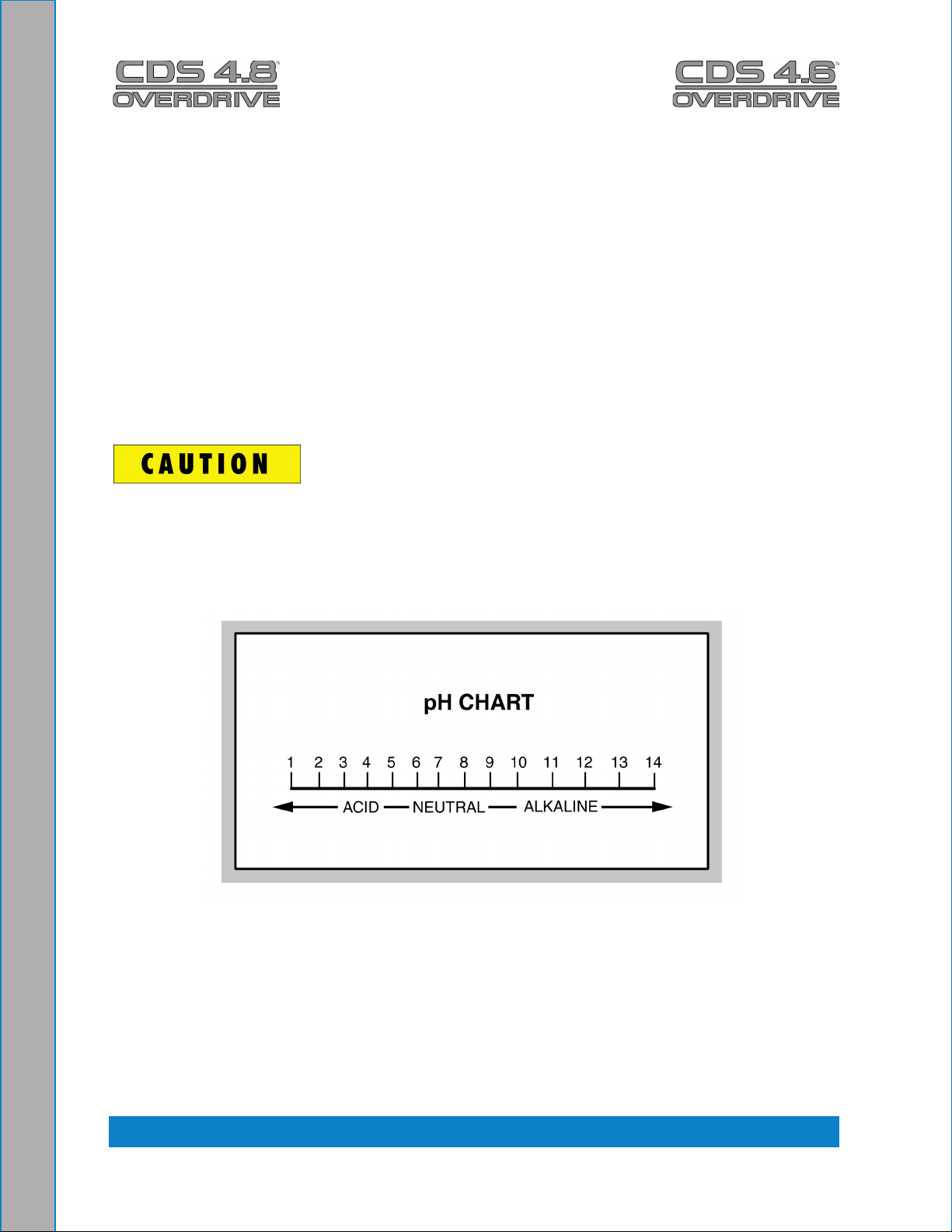
These harmful chemicals include concentrated acid (see the pH chart in Figure 2-1),
solvents (including d-Limonene), and some paint, oil and grease removers with a high
concentration of solvents.
THROUGH-FLOOR DRILLING: Be cautious when drilling holes through the van oor.
Many vans have critical components mounted directly below the van oor that could be
damaged by a misplaced drill bit.
LEVEL OPERATION: During operation, the vehicle must be parked on level ground
not to exceed + or - 10 degrees. Failure to ensure proper leveling may prevent proper
internal lubrication of engine, vacuum and/or high pressure components.
ACID RINSE AGENTS: Some acid rinse products can cause damage to internal machine
components. Failure to take appropriate measures to prevent acidic corrosion can result
in system failure and loss of warranty on affected parts.
HARD WATER PROTECTION: Failure to take appropriate measures to prevent scale
build up can result in system failure and loss of warranty on affected parts. Test the water
in your immediate and surrounding areas with hard water test strips. Assume all water
obtained from wells is hard. If you are operating in a hard water area at 3.0 grains or more
per gallon, use a water softening system.
FREEZE PROTECTION: Failure to take appropriate measures to prevent equipment
damage due to freezing can result in system failure and loss of warranty on affected
parts. Placing an electric heater in the vehicle or parking the vehicle indoors will help
ensure against freezing, but should not be the primary method of freeze protection.
1-5: General Information
Page 14

Machine Specications
Frame: 23” W x 41.5” H x 61.0” L
Weight: 912 lbs.
Construction: Tank: Marine Aluminum with Baked-on Epoxy Finish
Chassis: Painted Steel
Cowling: Fiberglass
Power Transfer: Electric Clutch-driven shaft, Key Activated
Vacuum Blower: 4.6 - 45 Tuthill/M-D Tri-Lobe
4.8 - 47 Tuthill/M-D Tri-Lobe
Water Pump: Plunger pump, 4.0 gpm (at high speed), 2,500 psi, electric clutch
control
Chemical System: Mechanical, Meter Controlled
Heating System: Multiple Heat Exchanger (1,200 psi pressure)
Dual Shell and Tube Exchangers
Optional Salsa Heat Package
Instruments:
Main Panel:
Electronic Tachometer, 0-3,000 rpm
Water Temperature Gauge, 0-320° F
Vacuum Gauge, 0-30” Hg
Hour Meter, Machine Run-Time
Keyed Ignition, Start/Stop
Electronic Circuit Protection Breaker, Re-settable
Machine Status Indicator Lamps
Chemical Flowmeter, 0-10 gph
Water Pressure Gauge, Liquid Filled, 0-1,500 psi
Side Panel:
Water Pressure Adjustment
Blower Lubrication Port
Water Temperature Adjustment Knob
High Pressure Solution Outlets, Quick-Disconnect
Fresh Water Inlet Fitting, Quick-Disconnect
Water Box Drain Valve
Chemical Controls
General Information: 1-6
Page 15

Recovery Tank: 100 gallon Aluminum
Cleaning Tool/
Wand: Stainless Steel
Replacement Grip
Rebuildable Solution Valve
High Pressure Hose:
1/4” High Temperature, Lined, Vinyl Covered
Hose rated to 2,200 psi, 250° F
Standard Equipment:
Power Transfer Package
Component Power Pack
Equipment Cowling
Vacuum Recovery Tank
Control Console
Dual Tool/Wand Hook-up
HydraMaster Heat Exchanger System
Freeze Guard System
Wheel Chock Set
Carpet Tool/Wand
150’ Solution Hose
150', 2" Vacuum Hose
10'. 1 ½” Vacuum Hose
50', Fresh Water Hose (Garden Hose)
10', 1 ½” Drain Line
5 gallon Chemical Jug
Chemical Jug Holder
Van Finish Package
Van Decal Package
Monogrammed Jacket
Owner’s Manual
Equipment Color Selection
Hushkit Silencer System (4.8)
1-7: General Information
Page 16

Responsibilities
Prior to the arrival of the unit, the van that it will be installed in should be delivered to the
installer.
Purchaser’s Responsibility
If you are the purchaser, it is the your responsibility to read the Owner’s Manual and to
familiarize yourself with the information contained herein, paying special attention to all
Warnings and Cautions.
Sales Representative’s Responsibility
Acceptance of Shipment
If the unit shows any outward signs of damage, do not sign the delivery receipt until 1.
you have closely inspected the unit and noted any damage on the delivery receipt.
The sales representative from whom you purchased your unit is responsible for 2.
supervising the correct installation of the unit in your vehicle and thoroughly training
you in its operation, maintenance and precautions.
Installation
Correctly installing the unit and recovery tank in your vehicle and securing them with •
bolts and tie down washers.
Checking the pump, vacuum blower and engine oil levels prior to starting the unit.•
Starting the unit to check the drive system and see that all other systems function •
normally.
Checking all hoses, tools/wands and accessories for correct operation.•
Training
A thorough review of the Owner’s Manual with the purchaser.•
Instruction in and familiarization with: •
How to correctly start up and shut down the unit1.
How to correctly clean with the unit2.
Where and how often to check and change component oil levels3.
How the unit’s systems work, how to troubleshoot the unit4.
How to do basic repairs5.
Safety precautions and their importance 6.
How to avoid freezing damage7.
How to avoid hard water damage8.
A thorough review of the unit warranty and warranty procedures.•
A thorough review of hard water precautions and warnings.•
How to determine hard water areas.•
Use of water softening systems.•
General Information: 1-8
Page 17

Local Water Precautions
The quality of water varies greatly. Many areas have an excess of minerals in the water
which results in what is commonly called “hard water.” These minerals tend to adhere to
the insides of heater coils and other parts of the machines causing damage and a loss of
cleaning effectiveness. This inuences the reliability and efciency of equipment in direct
proportion to the level of hardness.
HARD WATER ADVISORY
HydraMaster recognizes that any hard water deposits which might occur within the water
system of our truckmounts is a serious problem. The precision technology of truckmount
heat exchanger systems is intolerant of any foreign material. Hard water deposits will
ultimately decrease the performance of the system and are expected to seriously lower
the reliability of the machine.
To validate a machine’s warranty, HydraMaster requires that all machines operating in
designated “Hard Water Areas” (3.0 grains or more per gallon) be tted with a water
softening system, or a properly installed magnetic-type descaler must be used and
maintained. Periodic descaling or acid-rinsing alone is not adequate in these areas.
HydraMaster does not recommend any particular type or brand; however, the relative
effectiveness of some types of magnetic descalers or softeners may require additional
periodic use of descaling agents.
HydraMaster also recommends, in the strongest possible terms, that machines in all areas
be tted with a water softening system for improved operation and reliability.
Failure to take appropriate measures to prevent scale build up can result in system failure
and loss of warranty on affected parts.
1-9: General Information
Page 18

HARD WATER AREA MAP
The hard water map, shown in Figure 1-1, denes hard water areas in the lower 48 United
States which compromise uid related components such as hoses, ttings, heaters,
pumps, valves and water-cooled engines. For other countries, hard water area maps can
be obtained from geological societies.
Figure 1-1. Hard Water Map of Mainland United States
The map shown in Figure 1-1 is provided for general reference only. Water hardness in
your geographical location should be conrmed by testing.
General Information: 1-10
Page 19
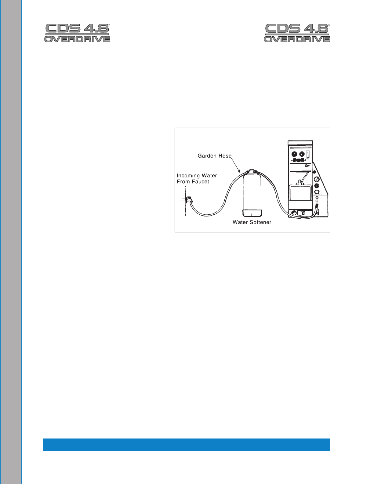
WATER SOFTENER
Cleaning efciency and equipment life is increased, chemical use decreased, and the
appearance of cleaned carpets enhanced when water softeners are incorporated in
hard water areas. HydraMaster strongly urges the use of water softener units with the
CDS 4.8/4.6 machines in areas exceeding 3.0 grains per gallon (see Figure 1-2).
Failure to use a water softener in these areas will invalidate the machine’s warranty.
Referring to the hard water area map shown Figure 1-1, determine the quality of water in
your area and take immediate action if
the water hardness exceeds 3.0 grains
per gallon.
The relatively low cost of a water
softener service is more than made up
for by an increased life of machine parts,
reduced chemical costs and continued
cleaning efciency. The water softener
will also increase the effectiveness of
the cleaning chemicals, therefore less
chemical will be needed.
Contact a water softener distributor in
your area for information on the rental
of a simple water treatment unit to
carry in your truck. Be sure to change
the water softener in accordance with the capability of the softener.
For example: If the softener will treat 900 gallons of water and the machine uses an
average of 30 gallons per hour, for an average of 5 hours a day, this equals 150 gallons
per day. In 6 days the machine would use 900 gallons of water. Therefore, the softener
would need to be changed every 6 working days for maximum softening.
Figure 1-2. Conguration of Water
Softener and CDS
1-11: General Information
Page 20

WASTE WATER DISPOSAL ADVISORY
There are laws in most communities prohibiting the dumping of recovered “gray” water
from carpet cleaning in any place but a sanitary treatment system.
The cleaning rinse water, recovered into your unit’s vacuum tank, contains materials
such as detergents, and must be safely processed before entering streams, rivers and
reservoirs.
In most cases, an acceptable method of waste water disposal is to discharge into a
municipal sewage treatment system after rst ltering out solid material such as carpet
ber. Access to the sanitary system can be obtained through a toilet, laundry drain, RV
dump, etc. Permission should rst be obtained from any concerned party or agency.
One disposal method which usually complies with the law is to accumulate the waste
water and haul it to an appropriate dump site. Another solution to the disposal problem
is to equip your CDS with an Automatic Pump-Out System (APO). These systems are
designed to remove waste water from the extractor’s recovery system and actively pump
the water through hoses to a suitable disposal drain.
HydraMaster makes an APO System which can be ordered with new equipment or
installed later.
When properly congured, the systems will continuously monitor the level of waste water
and pump it out simultaneously with the cleaning operation. The hidden benet of this
process is that the technician does not have to stop his/her cleaning to empty the recovery
tank.
IN ACCORDANCE WITH EPA, STATE AND LOCAL LAWS, DO NOT DISPOSE OF
WASTE WATER INTO GUTTERS, STORM DRAINS, STREAMS, RESERVOIRS, ETC.
The penalties for non-compliance can be serious. Always check local laws and regulations
to be sure you are in compliance.
General Information: 1-12
Page 21
2 - Chemicals and Cleaning
Your mobile carpet cleaning plant has been engineered using the latest and most
sophisticated technology available to produce the nest carpet cleaning results possible.
Despite this, it remains only a tool of the carpet cleaning trade and can produce only as a
good a job as the person operating it.
This section of the manual contains the following information:
Cleaning Precautions
Cleaning Stroke Procedure
Overwetting
The use of some chemicals through your mobile carpet cleaning plant can seriously
damage the internal plumbing, high-pressure pump, chemical pump and heat exchangers.
These harmful chemicals include concentrated acid, solvents (including d-Limonene),
and some paint, oil and grease removers with a high concentration of solvents (see pH
chart in Figure 2-1.
Figure 2-1. pH Chart
2-1: Chemicals and Cleaning
Page 22

CLEANING PRECAUTIONS
There are no short cuts to good carpet cleaning. It requires time, cleaning knowledge and
the use of good chemicals. Therefore, the manufacturer recommends the use of spotting
agents and trafc lane cleaners, as required, prior to the actual cleaning of carpeting.
HydraMaster also recommends only the use of chemicals containing rust and corrosion
inhibitors, and water softening agents to prevent chemical build-up which may lead to
component failure and warranty invalidation.
Some acid rinse products can cause damage to internal machine components. Failure
to take appropriate measures to prevent acidic corrosion can result in system failure and
loss of warranty on affected parts.
HydraMaster will not warranty parts that have been damaged from using acid products
that have obviously caused failures.
Avoid using detergents and chemicals which create foam when those products are
agitated because foam passing through the blower could lead to serious mechanical
failures. To ensure proper cleaning, use HydraMaster detergents and chemicals which
are formulated with built in anti-foaming agents. When cleaning surfaces with excessive
foaming residue, use HydraMaster de-foamer products as directed.
CLEANING STROKE PROCEDURE
To eliminate excess moisture remaining in the carpet ber and eliminate the sawtooth
appearance which results from diagonal movement of the cleaning tool, follow these
steps.
Always move the cleaning tool in smooth, forward and backward stroke1.
Apply slight pressure to the forward stroke while the solution is injected into the 2.
carpet.
When extracting (drying), apply rm pressure on the forward stroke to ensure a 3.
positive “lock” for the vacuum and minimize the “hopping” effect resulting on carpet
that is not smooth.
During the forward and reverse strokes, movement to the right or left should only be 4.
done at the extreme rear of the stroke.
Overlapping is also important to ensure even application of solution and prevent 5.
saturation when the cleaning tool is stopped twice at the same point at the rear of
the cleaning stroke Figure 2-2.
Chemicals and Cleaning: 2-2
Page 23
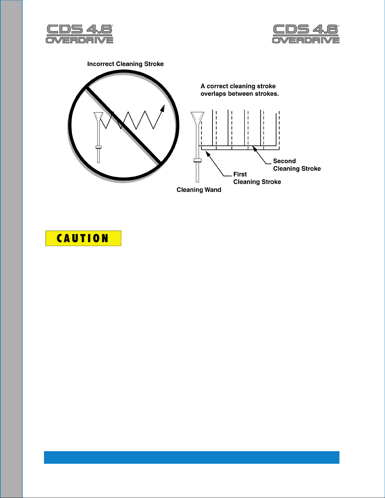
Figure 2-2. Cleaning Stroke Procedure
Failure to adopt the previous procedure can result in increased chance of “clean streaks,”
ber shrinkage, brown-out and longer drying periods.
OVERWETTING
Overwetting is annoying to all concerned, and sometimes leaves the customer with a bad
impression of the cleaning process used.
These are several conditions that will cause over-wetting
Too few vacuum strokes or improper saw-tooth vacuum strokes as shown in 1.
Figure 2-2.
Obstructed, cut or kinked hoses.2.
Vacuum tank drain valve left partially open.3.
Clogged vacuum blower lter or vacuum tank lid not sealing properly.4.
Cleaning a heavily foam-saturated carpet without defoamer. 5.
2-3: Chemicals and Cleaning
Page 24

3 - Operating Instructions
This section of the manual contains the following instructions:
Before Operating the CDS
CDS Start Up
CDS Flood Restoration Work
CDS Shut Down
3 Speed Throttle Control Function
BEFORE OPERATING THE CDS
Locate the unit and equipment in a well-ventilated area.1.
The CDS unit generates toxic fumes. Position the vehicle so that the fumes will be
directed away from the job site. Do not park where exhaust fumes can enter a building
through open doors, windows, air conditioning units or kitchen fans.
Check the fuel tank to be certain there is adequate fuel to complete the job.2.
Position the wheel chocks on one of the front tires.3.
If using a water supply hose which has not been used recently or if using a customer’s 4.
hose, rst connect the hose to the faucet and ush out any debris which may be in
the hose. Afterwards connect the hose to the unit.
Check the chemical jug to see if you have enough concentrated chemical to nish 5.
the job. If not, mix and ll a 5 gallon chemical jug.
Connect all required hoses.6.
When connecting the pressure hose to the pressure outlet connections at the front of 7.
the unit, go to the farthest area to be cleaned and connect to the cleaning tool. This
ensures that you have the proper length of hose required to perform the cleaning.
3-1: Operating Instructions
Page 25

CDS START UP
Make sure the vehicle’s gear select lever is in the Park position and the emergency 1.
brake is set
Start the vehicle’s engine.2.
Turn key on the CDS dash.3.
Select the cleaning speed appropriate for the cleaning job.4.
Turn on the PUMP CLUTCH switch. Adjust cleaning pressure to desired level.5.
Turn on the PUMP IN switch (if equipped).6.
Turn the heat control valve to “Max” only if you will be using water. Do not activate 7.
the heat exchanger during ood extraction work.
Turn the CHEMICAL SYSTEM valve to the “PRIME” position to purge any air from 8.
the system.
The prime hose is plumbed into the recovery tank. Leaving the valve in the “PRIME”
position will cause excessive chemical usage.
When the chemical begins to ow through the owmeter, with the ow indicator a.
reading maximum ow and the PRIME line pulsing, turn the CHEMICAL SYSTEM
valve to “ON”. Cap off vacuum if necessary.
While spraying the solution from the cleaning tool, adjust the chemical ow by b.
turning the CHEMICAL METERING CONTROL to the desired level.
Optional: Turn the APO switch ‘ON’ if using the Automatic Pump-Out feature.9.
The pump will not engage until the water level rises inside the recovery tank.
Now proceed with the cleaning operation.10.
The machine will automatically shut down when it reaches its full capacity due to the oat
switch located inside the recovery tank. When this occurs, turn the switch off and empty
the recovery tank. Then, turn the unit back on and continue to clean.
CDS FLOOD RESTORATION WORK
When using equipment for ood damage, adjust the high pressure pump to zero. This will
reduce the engine power load and save on fuel consumption.
Operating Instructions: 3-2
Page 26
CDS SHUT DOWN
Flush clear water through the chemical system for 10 seconds.1.
Open the water box drain and actuate the tool/wand valve to run fresh water through 2.
the water box, heat exchangers and cleaning tools.
If freeze guarding is necessary, perform the freeze guard procedure at this time. Draining
the water box to ½ full or less is recommended to reduce spillage inside the vehicle.
Rinse the system with vinegar on a weekly basis. Rinse the entire system with descaler
each month.
Lay vacuum hoses out in order for all moisture to be removed from the hoses. This 3.
prevents spillage of any dirty solution in your vehicle when storing the hoses.
Disconnect the hoses and put them away.4.
If you are using an outside water source, turn the water supply faucet off. Bleed 5.
pressure out of the supply hose by loosening the hose at the water supply. Unhook
the water supply hose and store it in the vehicle
Allow the unit to run for a few minutes with the vacuum hose disconnected in order 6.
to remove all moisture from the vacuum pump.
Plug the vacuum inlets. Spray lubricant into the lube port for about 5 to 10 seconds 7.
while the unit is running. This will lubricate the vacuum pump and prevent it from
rusting. (The lube port is located on the front panel above the pressure gauge.)
Remove the inlet plugs, then turn the 8. ignition “OFF” before draining the recovery
tank.
Turn the heat control valve to the ‘OFF’ position. This will help avoid engine overheat 9.
problems due to reduced coolant ow through the radiator.
Drain the recovery tank.10.
Do not dump waste in any area which might violate local, state or federal law. If
you have the optional Automatic Pump-Out (APO) system, drain the recovery tank into a
sanitary drain system.
When the recovery tank is drained, lift the recovery tank lid and remove the lter 11.
basket.
Clean out an12. y accumulated debris.
Rinse and re-install.13.
3-3: Operating Instructions
Page 27
3 speed Throttle Control function
▬ For GM Vans ▬
The GM Throttle Controller must meet certain “Chassis Ready” conditions to elevate the
engine rpm, which are as follows:
Parking Brake is set1.
Gear shift is in “Park”2.
Foot is off Service Brake (brake pedal)3.
Foot is off Accelerator Pedal4.
Vehicle is stationary (no speed)5.
Engine is started and idling6.
The A/C / Heater switch is in off position7.
The Throttle Controller must be initialized anytime the Data Link Cable (DLC) harness is
disconnected from the Data Link Connector. To initialize the system switch ignition key to
OFF position, plug in DLC harness, switch the ignition on, and then start the engine. This
allows the Throttle Controller to read the PCM engine computer.
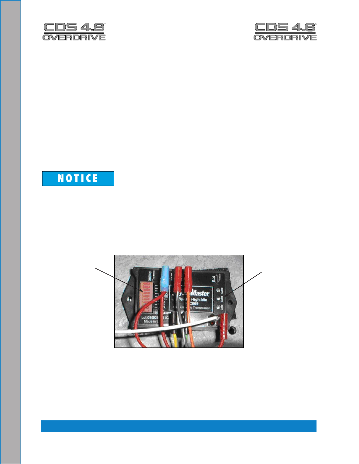
On the Throttle Controller, there are LED lights with corresponding labels to provide status
and problem detection information (refer to Figure 3-1 and Table 3-1).
LED LIGHTS WITH
LABELS
Location of Controller’s LED Lights Figure 3-1.
with Labels and RPM Trim Potentiometers
3 TRIM POTS
Operating Instructions: 3-4
Page 28
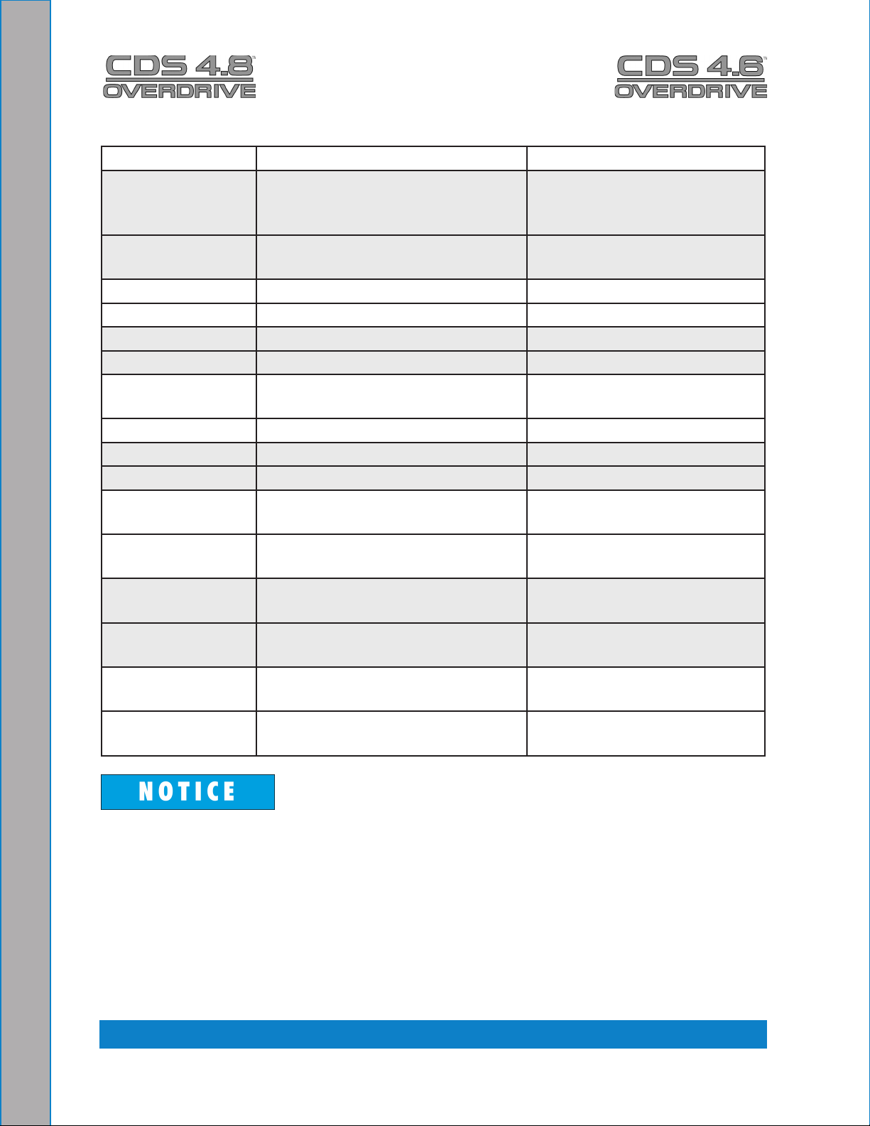
GM Throttle Controller LED FunctionsTable 3-1.
LED STATUS INDICATION
BUSS On Solid Unit ON and functioning
(harness connected to data
link)
BUSS Flashing Unit ON, but a problem was
detected
GEAR On Solid Transmission in PARK
GEAR Flashing Transmission NOT in Park
PK BRK On Solid Parking Brake Set
PK BRK Flashing Parking Brake is NOT set
SR BRK On Solid Service Brake is set (not
being used)
SR BRK Flashing Service Brake is NOT set
VSPEED On Solid Vehicle is stationary
VSPEED Flashing Vehicle is moving
RPM1 On Solid RPM1 mode selected, engine
at fast idle
RPM1 Flashing RPM1 mode selected, engine
not at fast idle
RPM2 On Solid RPM2 mode selected, engine
at fast idle
RPM2 Flashing RPM2 mode selected, engine
not at fast idle
RPM3 On Solid RPM3 mode selected, engine
at fast idle
RPM3 Flashing RPM3 mode selected, engine
not at fast idle
On GM gas engine vehicles, the PCM engine computer will cause the engine speed to
momentarily drop back to normal idle speed every time the air conditioner pump cycles on
or off. Make sure the operator of the CDS understands that the AC / HEAT switch needs
to be in the OFF position before activating the CDS unit.
3-5: Operating Instructions
Page 29
▬ For Ford Vans ▬
The Ford 3 Speed Throttle Controller must meet certain “Chassis Ready” conditions to
elevate the engine rpm, which are:
Parking Brake is set.1.
Gear shift is in “Park”.2.
Foot is off Service Brake (brake pedal).3.
Foot is off Accelerator Pedal.4.
Vehicle is stationary (no speed).5.
Brake light circuit is functional.6.
Engine coolant is above 140° F.7.
Transmission Oil Temperature is below 240° F.8.
Maximum Catalytic Temperature has not been met.9.
SEIC (Stationary Elevated Idle Control)* will be terminated by a safety condition violation.
For instance, the SEIC will be terminated if the service brake is depressed at any time
during its operation.
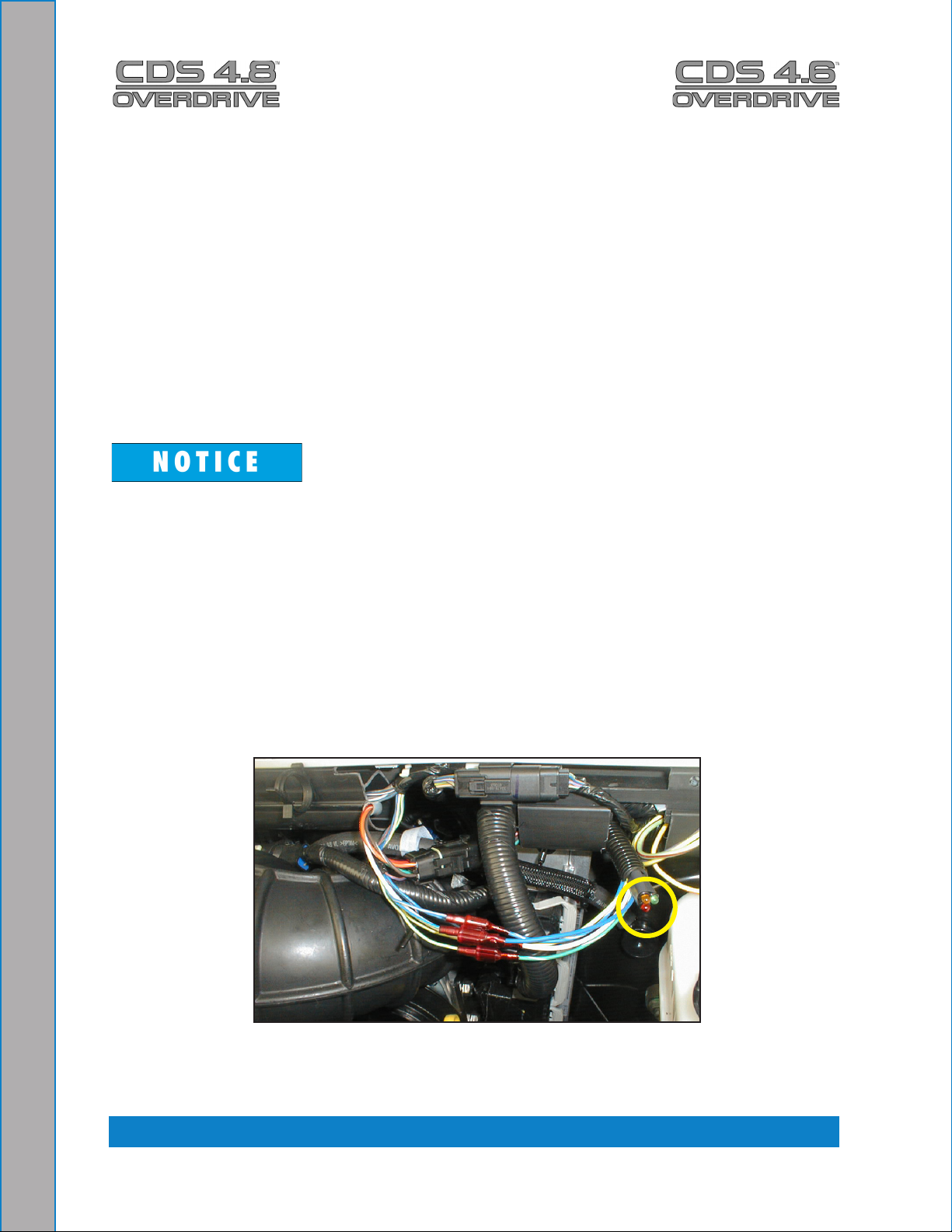
The 3 lights on the Throttle Control assembly indicate the following conditions (refer to
Figure 3-2 and Table 3-2):
RED LIGHT: the Throttle Control assembly is receiving power from the vehicle, but 1.
the SEIC process has not been initiated.
YELLOW LIGHT: all the “Chassis Ready” conditions have been met and the SEIC 2.
process has been initiated.
GREEN LIGHT: the Throttle Control assembly is receiving power from the CDS and 3.
the SEIC process is operational.
Location of 3 Lights on Throttle Control AssemblyFigure 3-2.
* SEIC is Ford’s onboard computer throttle control strategy.
Operating Instructions: 3-6
Page 30
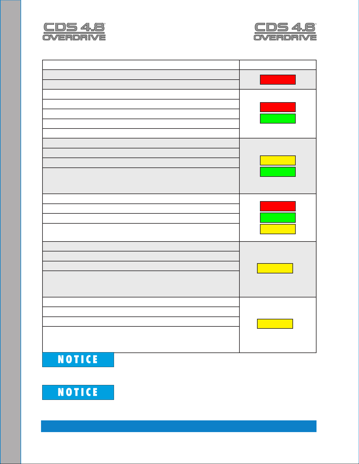
1.Van ignition ‘ON’
2.CDS ignition ‘OFF’
1.Van ignition ‘ON’
2.CDS ignition ‘ON’
3.Recovery tank NOT full
4.SEIC NOT active
“Chassis ready” conditions HAVE NOT been meta.
1.Van ignition ‘ON’
2.CDS ignition ‘ON’
3.Recovery tank NOT full
4.SEIC IS active
“Chassis ready” conditions HAVE NOT been a.
violated
1.Van ignition ‘ON’
2.CDS ignition ‘ON’
3.Recovery tank NOT full
4.SEIC IS active
“Chassis ready” conditions HAVE been violateda.
1.Van ignition ‘ON’
2.CDS ignition ‘ON’
3.Recovery tank IS full *
4.SEIC IS active
“Chassis ready” conditions HAVE NOT been a.
violated
1.Van ignition ‘ON’
2.CDS ignition ‘OFF’
3.Recovery tank NOT full *
4.SEIC IS active
“Chassis ready” conditions HAVE NOT been a.
violated
Ford Throttle Controller Light FunctionsTable 3-2.
WHEN… CONTROL LIGHT(S)
Red
Red
Green
Yellow
Green
Red
Green
Yellow
Yellow
Yellow
**
**
*Turn CDS ignition “OFF” before draining recovery tank.
**SEIC process will continue until a “chassis ready” condition has been violated. To clear
single yellow light conditions, van ignition needs to be turned “OFF”.
3-7: Operating Instructions
Page 31

4 - Freeze Guard
When operating the CDS 4.8 / 4.6 during the colder months of the year, ensure that
you properly freeze guard the system. No part of the CDS 4.6/4.8 System is covered by
warranty if machine damage occurs because of freezing.
This section of the manual includes information concerning:
Draining the CDS
Freeze Protecting Pump-In System
BE SURE YOUR MACHINE IS PROTECTED! Freezing will cause GRIEF, LOST MONEY,
and DOWN-TIME.
The following precautions are recommended prior to and during cleaning:
Run the machine before leaving for the rst job to ensure nothing has frozen the 1.
night before, including hoses and tool/wand.
Insulate the fresh water (garden) hose from the cold ground by running it through an 2.
extra 1½” vacuum hose.
Leave vehicle doors closed until you begin cleaning; afterwards, open slightly.3.
In colder climates, insulating the vehicle walls and oor boards will help protect the unit.
Do not procrastinate during the cleaning operation or the hot water solution line will 4.
also freeze on the ground. The solution line should be insulated in extremely cold
climates.
Whenever possible, store the van in a heated garage at night or over the weekend. 5.
If not possible, place a 1,500 Watt electric heater inside the vehicle, aimed directly
at the machine.
Never use a propane heater. It causes excessive moisture on the vehicle ceiling and the
possibility of it going out is higher.
If the machine and vehicle are left outside with a heater, drain water from the machine 6.
cleaning tools and hoses because they can be freeze-damaged also.
4-1: Freeze Guard
Page 32

DRAININg THE CDS
To drain the machine, follow these steps:
Before shutting off the machine, remove the chemical line from the chemical jug and 1.
place in a mixture of 50/50 antifreeze and water. Turn the CHEMICAL SYSTEM
valve to the “PRIME” position until coolant registers in the ow meter. With the
cleaning tool on, allow mixture to ll the remainder of the chemical system.
Open the water box drain valve and allow the water to drain thoroughly from the 2.
water box.
Close the water box drain and ll the water box with 50 / 50 antifreeze and water 3.
mixture. Run the unit for 1 minute to circulate the mixture through the machines
low-pressure hoses. Spray through the wand or other tool into a suitable container
until the water box shut-off switch activates (pump stops). This freeze guards the
high-pressure circuit
Open the water box drain and drain out the residual uid into a suitable container. 4.
This antifreeze solution may be retained for reuse (attach freeze guard tting to inlet
quick connect and vacuum water out of the inlet line).
One manufacturer of antifreeze cautions:
“WHEN DISPOSING OF USED ANTIFREEZE COOLANT: Follow local laws and
regulations. If required, dispose at facilities licensed to accept household hazardous
waste. If permitted, dispose in sanitary sewer systems. Do not discard into storm sewers,
septic systems, or onto the ground.”
This warning appears on the label of one brand of antifreeze:
“HARMFUL OR FATAL IF SWALLOWED. Do not drink antifreeze coolant or solution. If
swallowed, induce vomiting immediately. Call a physician. Contains Ethylene Glycol which
caused birth defects in animal studies. Do not store in open or unlabeled containers.
“KEEP OUT OF REACH OF CHILDREN AND ANIMALS.”
Freeze Guard: 4-2
Page 33

FREEZE PROTECTINg PUMP-IN SYSTEM
Drain the fresh water tank.1.
Remove the fresh water (garden) hose adapter from the pump-in pump hose and 2.
position the hose so it is pointing outside the van.
Turn on the pump-in pump and run for 1 - 2 minutes until all the water is purged from 3.
the hose.
The next time the CDS is used, it may take a few minutes before the water box begins to
ll.
4-3: Freeze Guard
Page 34

5 - Water and Chemical
System
The CDS 4.8 / 4.6 high-pressure water and chemical system has been designed to be
simple and trouble free.
This section of the manual explains:
Water and Chemical Flow Operation
Chemical System Maintenance
Chemical System Troubleshooting
WATER AND CHEMICAL FLOW OPERATION
The general concept of the water and chemical ow is as follows:
Water is fed into the CDS under tap pressure to the water box.•
The water is then pumped from the water box through the heating system, mixed with •
the chemical and then that mixed solution is pumped out to the cleaning tool/wand.
After the solution is applied to the carpet, it is recovered by the vacuum system and •
carried back to the recovery tank.
The chemical pump draws the chemical from the inlet lter which is in the chemical
container. The chemical solution ows through the owmeter, indicating the ow of
chemical being used in gallons/hour. The chemical then ows through the chemical pump
to the chemical selector valve. The CHEMICAL SYSTEM valve can be used to prime the
pump (evacuate air from the system), inject chemical into the system or turn the chemical
ow off. When the CHEMICAL SYSTEM valve is in the “ON” position, chemical ows
through the metering valve, and is injected into the heated water path just prior to its
leaving the machine.
The low water oat switch in the water box is a safety switch that is designed to protect
your system from sudden or unexpected loss of water supply. If, for example, the water
source at the house were turned off, the water level of the water box would drop, activating
the low water oat switch, which automatically disengages the system and prevents the
water pump from running dry.
The desired chemical injection ratio may be obtained by adjusting the chemical metering
valve when spraying of water through the cleaning tool.
5-1: Water and Chemical System
Page 35

CHEMICAL SYSTEM MAINTENANCE
The chemical lines may need to be ushed with vinegar periodically to prevent abnormal
chemical build-up.
To ush the chemical system:
Set the CHEMICAL FLOWMETER to10 gph.1.
Remove the clear plastic hose from the chemical jug and insert it into a 1-quart 2.
container of vinegar.
Spray water from the tool/wand until the vinegar is gone.3.
Repeat the process with 1 quart of clear water to void all lines of vinegar.4.
Water and Chemical System: 5-2
Page 36

Chemical System Troubleshooting
1.0. SYSTEM WILL NOT PRIME
1.1. Check valves in
chemical pump are faulty.
1.2. Chemical pump
diaphragm is faulty.
1.3. Check valve in high
pressure pump (the one that
the chemical pump attaches
to) is faulty.
1.4. Filter on feed line in
chemical jug is clogged.
1.5. Feed line from chemical
jug is loose, pinched or cut.
1.6. Three-way prime valve
is faulty.
If the chemical system has been run dry, it may be necessary to prime the chemical
system to purge all of the air from the system.
Remove valves and inspect. Clean or replace as
necessary.
Remove and inspect. Replace as necessary.
Remove valve and inspect. Clean or replace as
necessary.
Inspect and clean.
Inspect and repair.
Check valve for leaks between ports. Replace as
necessary.
2.0. CHEMICAL FLOW IS UNSTAbLE OR LOW
2.1. Air in lines. Check that all ttings and connections are tight and in
good condition. Repair or replace as necessary.
2.2. Filter screen in
chemical jug is partially
clogged.
2.3. Three-way chemical
valve is faulty.
2.4. Chemical metering
valve is faulty or partially
obstructed.
2.5. High pressure check
valve is faulty.
Inspect and clean.
Inspect valve for leaks between ports. Replace as
necessary.
Inspect valve and clean or replace as necessary.
Remove and inspect. Clean or replace as necessary.
5-3: Water and Chemical System
Page 37

3.0. CHEMICAL jUg FILLS WITH WATER
3.1. Three-way chemical
valve is defective.
3.2. Inlet check valve in
chemical pump is faulty.
Inspect valve for leaks between ports. Replace as
necessary.
Remove and inspect valve. Clean or replace as
necessary.
4.0. CHEMICAL IN WATER BOX
4.1. Chemical pump
diaphragm is faulty.
4.2. High-pressure check
valve is faulty.
Remove and inspect. Replace as necessary.
Remove and inspect. Clean or replace as necessary.
Water and Chemical System: 5-4
Page 38

6 - Water Pump Maintenance
The CDS’ water pump features a dynamic low-pressure seal retainer, an innovative
intermediate ring, and superior low-pressure and high-pressure seals. With its ceramic
plungers and nickel-plated forged brass manifold, this high-temperature pump is ideal for
use in carpet cleaning.
You must perform daily and periodic maintenance
on the pump to maintain maximum performance
of seals and valves.
This section of the manual explains:
Daily Maintenance
Periodic Maintenance
Water Pump Troubleshooting
DAILY MAINTENANCE
Check the oil level and the condition of the 1.
oil. The oil level should be up to the center
of the sight glass on the back of the pump.
Use a SAE15W40 oil.2.
If the oil becomes discolored and contaminated, one of the oil seals may be damaged.
Refer to the Pump Owner’s Manual, included with the CDS 4.8 / 4.6 Owner’s Manual, for
more information.
Do not operate the pump if the crankcase has been contaminated with water.
Do not leave contaminated oil in the pump housing or leave the housing empty. Remove
contaminated oil as soon as it is discovered and replace it with clean oil.
Do not turn the drive shaft while the oil reservoir is empty.
Protect the pump from freezing.
6-1: Water Pump Maintenance
Page 39

PERIODIC MAINTENANCE
Change the oil after the rst 50 hours of operation, with the pump stopped and the oil still
warm, and after every 300 operating hours or 3 months of operation. When changing the
oil, remove the drain plug on the oil drain hose so all oil and accumulated sediment will
drain out.
The initial oil change is recommended for no other reason than to eliminate impurities that
may be in the oil during the running-in phase. If these impurities are not removed, but are
allowed to remain in the oil, they may cause premature wear to the moving parts and the
oil seals.
If the pump works in conditions with high humidity and with sharp temperature changes,
condensation may appear inside the crankcase. Condensation mixing with the oil can
change the oil’s properties, which is easy to detect because the oil changes to a white,
milky color.
If the pump does not have excessive water leaking from the packings, and the oil becomes
milky, the oil has to be changed more frequently.
Water Pump Maintenance: 6-2
Page 40

Water Pump Troubleshooting
1.0.WILL NOT COME UP TO NORMAL CLEANINg PRESSURE
1.1.Pressure adjusting valve
is defective or dirty.
1.2.Worn seals or valves in
pump.
1.3. Pump rpm is too low. Check engine rpm and adjust as necessary. Check for
1.4. Primary system control
orice is missing or loose*.
1.5. Primary orice is worn.* Measure orice size and replace as necessary.
*Applies to SALSA option only.
Disassemble valve. Repair or replace as necessary.
Test pump output volume directly from pump at normal
operating rpm. If volume is below manufacturers
specications, replace seals and inspect for defective
valves.
loose pump belt. Adjust tension as necessary.
Remove lter and inspect. Tighten or replace as
necessary.
2.0. NO PRESSURE READINg ON PSI gAUgE
2.1. Pump switch is not
turned on.
2.2. No water in water box. Refer to section 5 of this manual.
2.3. Pump belt is broken. Replace belt.
2.4. Pump clutch is not
activated. There is no water
in water box
2.5. Pump clutch is not
activated. There is water in
the water box.
Turn on switch
Check system back to source to locate cause of
interruption to water ow.
2.5.1. Check for 12 volts at clutch. If 12 volts is present,
replace clutch.
2.5.2. If 12 volts is not present, check power to the lowwater relay. If there is 12 volts at the relay, check low
water switch in water box.
2.5.3. If low water switch has no continuity when oat is
up, replace the switch. If switch is good, replace the low
water relay.
6-3: Water Pump Maintenance
Page 41

3.0. PSI gAUgE READS NORMAL; LOW PRESSURE FROM TOOL/
WAND
3.1. There is a restriction in
the cleaning tool/wand.
3.2. There is a defective quick
connect in the system.
3.3. There is a restriction in
one of the solution hoses.
3.4. There are hard water
deposits restricting the
system between the heat
exchanger and the highpressure solution connection
at the front of the machine.
Inspect tool jet and clean or replace as necessary.
Inspect any lters in the cleaning tool and clean or
replace as necessary.
Inspect each quick connect and replace as necessary.
Remove quick connects and inspect hoses. Clean or
replace as necessary.
Descale the machine. If this doesn’t solve the problem,
disassemble this portion of the system and locate
restriction.
4.0. PRESSURE PULSATION
4.1. Water in the water-box
is too hot and is approaching
boiling point.
4.2. There is an air leak
between the water box outlet
and the pump inlet.
4.3. One of the intake or outlet
valves in the high-pressure
pump is defective or is being
held open by debris.
Check temperature of water in the water-box.
Physically check all hoses and ttings for cuts, breaks,
cracks or tightness. Repair as necessary.
Remove each valve and inspect for correct operation.
5.0.WATER bOx EMPTY OR FILLS SLOWLY
5.1. There is a restriction in
the water supply system.
5.2. The oat valve in the
water box is defective
Water Pump Maintenance: 6-4
Inspect the supply system from the source through the
incoming quick connect for kinks, clogs or restricted
lters. Clean or repair as necessary.
Replace.
Page 42

6.0. WATER bOx OvERFLOWS
6.1. There is either debris
caught in the valve or the
valve seal is bad.
6.2. The oat has absorbed
water and has lost buoyancy.
6.3. The oat has come out
of adjustment.
Replace.
Replace.
Re-adjust oat as necessary.
6-5: Water Pump Maintenance
Page 43

7145 Rev. C
7 - Assemblies and Parts Lists
CDS Machine Assembly - Front ViewFigure 7-1.
7-1: Assemblies and Parts Lists
Page 44

7145 Rev. C
CDS Machine Assembly - Rear ViewFigure 7-2.
Assemblies and Parts Lists: 7-2
Page 45

CDS Machine Assembly Parts List
Item Part Number Description Qty Item Part Number Description Qty
1 - - - Assembly, Recovery Tank - CDS 4.8 1
2 - - - Pump & Blower Assembly - CDS 4.8 1
3 000-068-588 Hose, 3/8" X 36" Lg. Throb - CDS 1
4 000-068-030 Hose, 5/32" ID Vacuum - Bulk 10 ft
5 000-068-459 Hose, 3/4" ID Green Stripe - Bulk 18 ft
6 000-068-085 Hose, 3/8" Hi Temp Black - Bulk 73"
7 000-068-706 Hose, 3/16" X 70" Lg. Teon W/ F JIC Ends 1
8 000-033-005 Clamp, Size #5 Hose 2
9 000-033-020 Clamp, Size #16 Hose 2
10 000-033-013 Clamp, #48 Hose (3") 2
11 000-068-764 Hose, Ø3.0" X 15 Lg. Flexible Wire Reinforce 34"
12 000-068-777 Hose, 1" X 45" Lg. Suction 1
13 000-033-132 Clamp, 1-1/2" T-Bolt 2
7-3: Assemblies and Parts Lists
Page 46

6977 Rev. B
CDS Recovery Tank Assembly - Front ViewFigure 7-2.
Assemblies and Parts Lists: 7-4
Page 47

6977 Rev. B
CDS Recovery Tank Assembly - Rear ViewFigure 7-3.
7-5: Assemblies and Parts Lists
Page 48

CDS Recovery Tank Assembly Parts List
Item Part Number Description Qty Item Part Number Description Qty
1 000-159-130 Tank, 100 Gallon Universal Recovery - Weldment 1
2 Assembly, Recovery Tank Cover - 100 Gallon 1
3 000-001-135 Adapter, Tank To Ø3.0 X 90° Blower Hose 1
4 000-049-152 Filter, Recovery Tank Basket 1
5 See Notes Assembly, Vacuum Relief Valve - URT 1
6 000-049-153 Filter, Flat - Universal Recovery Tank 1
7 000-015-932 Bracket, Flat Filter Securing 1
8 000-049-154 Deector, Air - Universal Recovery Tank 1
9 000-057-206 Gasket, Adapter - URT 2
10 000-140-023 Rivet, Ab8-6a Aluminum Pop 6
11 000-106-046 Plug, 1-1/4" NPT 1
12 000-157-091 Float, Lever Switch 1
13 000-033-023 Clamp, 3/4" Nylon Hose 4
14 000-143-126 Screw, #10-24UNC X 0.50" Lg. Hex Head 6
15 See Notes Label, Set CDS 4.6/4.8 Common 1
16 000-086-008 Latch, Bungie 1
31 601-050-105 Assembly, Water Box 1
32 000-166-002 Assembly, Soap Jug Tray 1
33 601-050-111 Assembly, Dual Heat Exchanger 1
34 000-174-001 Washer, #10 Flat 6
35 000-067-031 Hinge, Dash Box 1
36 000-094-113 Nut, 1/4"-20UNC Neoprene Wellnut 4
37 000-143-166 Screw, #10-24UNC X 3/8" Lg. Hex Head 3
38 000-174-060 Washer, 1/4" Rubber Backed 4
39 000-106-049 Plug,1" NPT Black Nylon 1
40 000-143-002 Screw, 1/4"-20UNC X 1.00" Lg. Hex Head 8
41 000-094-009 Nut, 1/4"-20UNC Nylock 8
42 000-174-036 Washer, #10 Flat Rubber Backed 3
43 000-094-034 Nut, #10-24UNC Nylock S/S 3
44 000-174-015 Washer, #10 Outside Star 5
45 000-094-004 Nut, #10-24UNC Hex 5
46 000-143-064 Screw, #10-24UNC X 050" Lg. Flat Head 4
17 000-143-539 Screw, #6-32UNC X 0.50" Lg. Button Head 2
18 000-094-063 Nut, #6-32UNC Nylock 2
19 000-174-019 Washer, 1/4" Lock 2
20 000-174-003 Washer, 1/4" Flat 18
21 000-106-019 Plug, 1-1/2" NPT 1
22 000-052-763 Nipple, 1-1/2" IPS Close S/S 1
23 000-169-022 Valve, 1-1/2" Full Port Ball 1
24 000-052-226 Insert, 1-1/2" NPT X 1-1/2" Barb (Grey) 1
25 000-052-082 Elbow, 1/4" NPT Street X 45° 1
26 000-052-102 Insert, #46 (1/4" NPT X 3/8" Barb) 3
27 000-052-085 Elbow, 1/4" NPT Street 1
28 See Notes Label, Maintenance & Lube Schedule 1
29 000-143-333 Screw, 1/4"-20UNC X 0.50" Lg. Hex Head 2
30 000-174-029 Washer, 3/8" Rubber Backed 2
Assemblies and Parts Lists: 7-6
47 000-068-459 Hose, 3/4" ID Green Stripe 1
48 000-033-020 Clamp, Size #16 Hose 2
49 000-068-017 Hose, 3/8" Bulk 3.5 ft
50 000-033-005 Clamp, Size #5 Hose 2
51 000-143-114 Screw, #10-24UNC X 0.50" Lg. Flat Head 2
52 601-013-001 Stabilizer, Instrument Panel To Recovery Tank 1
53 000-068-018 Hose, 1/2" ID Rubber - Bulk 3.75 ft
54 000-068-734 Hose, 1/2" X 42.5 Lg. W/ 3/8" NPT & 3/8" SAE F Ends 1
55 000-068-326 Hose, 3/8" Id. Clear W/ Braid 1
56 - - - Assembly, Dash Box 1
57 000-068-203 Hose, 3/16" X 34" Lg. 1/4" FJIC X 1/4" FJIC 1
58 - - - Assembly, Instrument Panel 1
59 000-049-118 Filter, Chemical Inlet High Pressure 1
Page 49

8
1
7
6
3
4
9
10
11
9
5
2
7151
CDS Recovery Tank Cover AssemblyFigure 7-4.
CDS Recovery Tank Cover Assembly Parts List
Item Part Number Description Qty Item Part Number Description Qty
1 000-041-447 Cover, 100 Gallon Universal Recovery Tank - Weldment 1
2 000-078-039 Vacuum Inlet Stopper Assembly - Recovery Tank 1
3 000-057-015 Gasket, 1-1/2” Bulkhead Fitting 2
4 000-052-219 Adapter, 2” NPT x 2” F Slip 2
5 000-143-539 Screw, #6-32UNC x 0.50” Lg. Button Head Allen 2
6 000-086-008 Latch, Bungie - Strike 1
7 000-094-063 Nut, #6-32UNC Nylock 2
8 000-052-222 Elbow, 2” Barb x 2” FPT 2
9 000-057-202 Gasket, End - Recovery Tank 2
10 000-057-203 Gasket, Middle - Recovery Tank 3
11 000-057-205 Gasket, Side - Recovery Tank - 100 Gallon 2
7-7: Assemblies and Parts Lists
Page 50

6988 Rev. C
CDS Instrument Panel Assembly - Front ViewFigure 7-5.
Assemblies and Parts Lists: 7-8
Page 51

6988 Rev. C
CDS Instrument Panel Assembly - Rear ViewFigure 7-6.
7-9: Assemblies and Parts Lists
Page 52

CDS Instrument Panel Assembly Parts List
Item Part Number Description Qty
1 000-100-168 Panel, Instrument 1
2 See Notes Assembly, Hi-psi Manifold 1
3 See Notes Assembly, By-Pass Valve 1
4 000-105-012 Plate, Machine Serial ID 1
5 000-074-030 Meter, Chemical Flow Raw 1
6 000-174-008 Washer, 5/8" Flat 4
7 000-169-064 Valve, 3/8" NPT Full Port Ball 1
8 000-052-051 Quick Connect, 440 Female w/ EPDM O-Ring 2
9 000-106-029 Plug, 1" Hole 1
10 000-052-052 Quick Connect, 660 3/8" Brass w/ EPDM O-Ring 1
11 000-052-281 Nipple, 3/4" NPT X 3/4" Male Garden Hose 1
12 000-052-104 Insert, #66 (3/8" NPT X 3/8" Barb) 1
13 000-052-096 Insert, #F23 (1/8" FPT X 3/16" Barb) 1
14 000-060-002 Grommet, Large Wiring 1
15 000-057-055 Gasket, Garden Hose 1
Item Part Number Description Qty
32 000-169-160 Valve, Chemical Metering 1
33 000-052-069 Nipple, 1/8" NPT Hex 2
34 000-174-030 Washer, 5/8" Id X 7/8" OD X 0.010" Thk 1
35 000-094-098 Nut, 7/16"-24 UNF - 2 watt Metering Valve 1
36 000-052-531 Elbow, 1/8" NPT X 1/4" SAE 1
37 000-052-084 Elbow, 1/8" NPT Street 1
38 000-052-099 Insert, #26 (1/8" NPT X 3/8" Barb) 3
39 000-068-491 Hose, 3/16" X 10" Lg Teon 1/4" NPT X 1/4" JIC F 1
40 000-068-518 Hose, 3/16" X 18.25" Lg. Teon w/FJIC Ends 1
41 000-052-022 Tee, 3/8" Insert 1
42 000-052-089 Elbow, 1/8" NPT Female 1
43 000-174-001 Washer, #10 Flat 6
44 000-143-166 Screw, #10-24 UNC X 3/8" Lg. Hex Head 2
45 000-068-017 Hose, 3/8" Bulk 1
46 000-068-017 Hose, 3/8" Bulk 1
16 000-074-007 Gauge, Pressure 0 -1500 psi 1
17 000-052-272 Cup, Gravity Feed Oil Blower Lube Port 1
18 000-027-014 Cap, Garden Hose 1
19 000-174-050 Washer, 1" Flat 1
20 000-135-052 Regulator, Hi psi Snubber 1
21 000-169-009 Valve, 3/4" FPT Swing Check 1
22 000-052-338 Insert, #1212 (3/4" NPT X 3/4" Barb) 1
23 000-052-088 Elbow, 1/4" FPT X FPT 1
24 000-174-005 Washer, 3/8" Flat 2
25 000-052-128 Nipple, 3/8" NPT X 3/8" M Propane 2
26 000-174-063 Washer, 1.5" OD. X 1.073" ID X 0.075" Thk. 1
27 000-174-012 Washer, 1/2 SAE H/D 2
28 000-140-015 Rivet, 1/8" X 1/4" Lg. Pop 2
29 000-169-201 Valve, 3/4" Heater Panel Mount 1
30 000-052-756 Insert, 3/4" NPT X 3/4" Elbow 2
31 000-169-017 Valve, 3-Way Ball O-Ring Style 1
47 000-033-005 Clamp, Size #5 Hose 4
48 000-052-530 Nipple, 1/4" SAE X 1/8" NPT 1
49 000-131-027 Trimlok, 1/8" X 3/16" Lg. 1
50 000-174-014 Washer, #10 Lock 2
51 000-174-007 Washer, 1/2" Flat 1
52 000-143-327 Screw, #10-32UNF X 0.50" Lg. Hex Head 2
53 Label, Instrument Panel-CDS 4.6/4.8 1
54 Label, Bottom-Instrument Panel-CDS 4.6/4.8 1
55 000-068-757 Hose, 1/2" X 20.5" Lg. Rubber W/3/8" NPT X 3/8" S 1
Assemblies and Parts Lists: 7-10
Page 53

2
43
5
6
7
6
10
1
11
13
1217
1614
15
8
9
6091 Rev. B
CDS Hi-PSI Manifold AssemblyFigure 7-7.
CDS Hi-PSI Manifold Assembly Parts List
Item Part Number Description Qty Item Part Number Description Qty
1 000-052-528 Nipple, 3/8” MJIC x 3/8” NPT 1
2 000-052-071 Nipple, 1/4” NPT Hex 2
3 000-090-008 Manifold, Hi Pressure 1
4 000-106-002 Plug, 1/4” NPT Hex 1
5 000-052-530 Nipple, 1/8” MNPT x 1/4” SAE 1
6 000-052-074 Nipple, 3/8” NPT Hex 2
7 000-169-186 Valve, 3/8” FPT x 3/8” FPT 100 PSI Check 1
8 000-149-039 Sender, Temperature 1
10 000-052-113 Cross, 3/8” FPT 1
11 000-050-060 Bushing, 3/8” NPT x 1/8” FPT 1
12 000-052-582 Nipple, Tee Jet Style Collar x 1/8” NPT 1
13 000-094-028 Nut, Brass Jet Assembly 1
14 000-052-153 Housing, Stabilizer Nozzle 1
15 000-052-586 Nipple, 1/8” FPT x 1/4” SAE 1
16 000-049-052 Filter Cartridge, 1/4” 1
17 000-180-009 Orice, 0.027” Plate 1
9 000-052-061 Bushing, 3/8” NPT x 1/4” FPT 1
7-11: Assemblies and Parts Lists
Page 54

CDS By-Pass Valve AssemblyFigure 7-8.
3
2
10
5
6
9
7
11
4
1
5
8
12
14
13
CDS By-Pass Valve Assembly Parts List
6989 Rev. A
Item Part Number Description Qty
1 000-169-188 Valve, PSI Regulator 0-1500 psi - Modied 1
2 000-015-515 Bracket, By-Pass Valve Mounting 1
3 000-027-008 Cap, 3/8” FPT 1
4 000-052-764 Elbow, 1/4” SAE x 3/8” MNPT x 90° 1
5 000-052-023 Tee, 3/8” NPT Male Street 3
6 000-052-528 Nipple, 3/8” M JIC x 3/8” NPT 1
7 000-052-105 Insert, #68 (3/8” NPT x 1/2” Barb) 1
8 000-169-027 Valve, Thermal Relief 165° F 1
9 000-052-099 Insert, #26 (1/8” NPT x 3/8” Barb) 1
10 000-106-008 Plug, 3/8” NPT Allen Head 1
11 000-143-126 Screw, #10-24UNC x 0.50” Lg. Hex Head 2
12 000-052-128 Nipple, 3/8” NPT x 3/8” Male Propane 1
13 000-174-001 Washer, #10 Flat 2
14 000-174-014 Washer, #10 Lock 2
Assemblies and Parts Lists: 7-12
Page 55

3802 Rev. N
CDS 4.8 Pump and Blower Assembly - OverviewFigure 7-9.
7-13: Assemblies and Parts Lists
Page 56

CDS 4.8 Pump and Blower Figure 7-10.
Assembly - Parts View
3802 Rev. N
Assemblies and Parts Lists: 7-14
Page 57

CDS 4.8 Pump and Blower Assembly Parts List
Item Part Number Description QtyItem Part Number Description Qty
1 000-055-028 Frame Pump And Blower 1
2 000-008-020 Bearing, Pillow Block - 1-3/16" Bore 2
3 000-020-019 Bushing, #H X 7/8" Bore 1
4 000-052-505 Zerk Fitting, 1/8" MPT Grease Fitting - Straight 2
5 000-094-100 Nut, 3/8-16, Nylock 5
6 000-111-147 Blower, 4007 Dominator 1
7 000-139-021 Snap Ring, 1-3/16" Shaft 2
8 000-143-018 Screw, 3/8-16UNC X 1" Hex Head - Grade 8 4
9 000-174-004 Washer, 5/16" Flat 12
10 000-001-042 Adapter, Blower Outlet - CDS 4.8 1
11 000-150-040 Shaft, Drive Sprocket - CDS 4.8 1
12 000-108-065 Protector, Cat Pump Belt Shield 1
13 000-154-146 Spacer, Powerpack - Front - CDS 4.8 Ford 2 1
14 000-154-147 Spacer, Powerpack - Rear - CDS 4.8 Ford 200 1
15 000-033-057 Clamp, 1" Cushion Loop 1
16 000-052-061 Bushing, 3/8" NPT X 1/4" FPT 2
32 000-174-001 Washer, #10 Flat 1
33 000-143-132 Screw, #10-24UNC X 0.75" Lg. Hex Head 1
34 000-077-010 Key, 1/4" X 1-1/2" Lg. 1
35 000-020-020 Bushing, 7/8" Taper-Lock 1
36 000-020-026 Bushing, 1-1/8" Taper-Lock 1
37 000-077-012 Key, 3/16" X 2.5" Lg. Class 2 Fit 1
38 000-109-057 Pulley, 40 Tooth Gt2 8mx-10s-21 Engine & Blower 1
39 000-109-058 Pulley, 56 Tooth Gt2 8mx-56s-21 Engine & Blower 1
40 000-143-373 Screw, 1/4"-20UNC X 2"G. Hex Head Grd 5 1
41 000-143-548 Screw, 1/4"-20UNC X 2.00" Lg. Hex Head 1
42 000-149-010 Sensor, CDS Magnetic Tach 1
43 000-154-153 Spacer, Tach, Sensor - CDS 4.8 1
44 000-109-009 Pulley, 2.75" X 0.88" Pump Drive 1
45 000-015-801 Bracket, Blower Mounting - CDS 4.8 2
46 000-015-930 Bracket, Tach, Magnetic Extension N/S - CDS 1
47 000-010-052 Belt, Polychain Gt 1
17 000-052-083 Elbow, 3/8" NPT Street X 45° 1
18 000-052-084 Elbow, 1/8" NPT Street 1
19 000-052-293 Insert, #23 (1/8" NPT X 3/16" Barb) 2
20 000-094-010 Nut, 1/4"-20UNC Hex S/S 2
21 000-143-096 Screw, 3/8"-16UNC X 1.00" Lg. Hex Head 2
22 000-143-260 Screw, 3/8"-16UNC X 8.00" Lg. Hex Head W/ 6" Thr 1
23 000-174-021 Washer, 3/8" Lock 7
24 000-143-025 Screw, 3/8"-16UNC. X 1.25" Lg. Hex Head Gr. 8 4
25 000-143-013 Screw, 5/16"-18UNC X 1.00" Lg. Grade 8 5
26 000-174-018 Washer, 5/16" S/S Lock 5
27 000-174-002 Washer, 1/4" Flat 6
28 000-174-017 Washer, 1/4" Lock 2
29 000-143-240 Screw, 1/2"-13UNC X 1.75" Lg. Hex Head - Grade 4
30 000-174-012 Washer, 1/2 SAE H/D 4
31 000-094-037 Nut, 1/2-13 UNC. 2 Way Locking 4
48 000-068-149 Hose, CDS Blower Oil Drain 2
49 000-077-001 Key, #3 & #4 Vacuum Pump Drive 2
50 000-174-003 Washer, 1/4" Flat 4
51 000-094-012 Nut, 5/16-18"UNC Hex 2
52 000-143-002 Screw, 1/4"-20UNC X 1.00" Lg. Hex Head 1
53 - - - Assembly, Pump 1
54 000-108-109 Protector, Pump Drive Belt 1
55 000-143-141 Screw, 1/4"-20UNC X 1/2" Lg. Whiz Lock 2
56 000-174-019 Washer, 1/4" Lock 2
57 000-052-069 Nipple, 1/8" NPT Hex 1
58 000-001-090 Adapter, Blower Inlet - CDS 4.6 1
59 000-052-092 Tee, 1/8" FPT 1
60 000-143-094-1 Screw, 3/8"-16UNC X 3/4" Lg. Socket Head 4
61 000-109-043 Pulley, Ak51h 1
62 000-010-065 Belt, #9345 Pump Drive 1
7-15: Assemblies and Parts Lists
Page 58

4431 Rev. O
CDS 4.6 Pump and Blower Assembly - OverviewFigure 7-11.
Assemblies and Parts Lists: 7-16
Page 59

CDS 4.6 Pump and Blower Figure 7-12.
Assembly - Parts View
4431 Rev. O
7-17: Assemblies and Parts Lists
Page 60

CDS 4.6 Pump and Blower Assembly Parts List
Item Part Number Description Qty
1 000-055-028 Frame Pump And Blower 1
2 000-008-020 Bearing, Pillow Block - 1-3/16" Bore 2
3 000-020-019 Bushing, #H X 7/8" Bore 1
4 000-052-505 Zerk Fitting, 1/8" MPT Grease Fitting - Straight 2
5 000-094-100 Nut, 3/8-16, Nylock 5
6 000-111-145 Blower, 4005 Dominator 1
7 000-139-021 Snap Ring, 1-3/16" Shaft 2
8 000-143-018 Screw, 3/8-16UNC X 1" Hex Head - Grade 8 4
9 000-174-004 Washer, 5/16" Flat 12
10 000-150-040 Shaft, Drive Sprocket - CDS 4.8 1
11 000-108-065 Protector, Pump Belt Shield 1
12 000-154-146 Spacer, Powerpack - Front - CDS 4.8 Ford 2 1
13 000-154-147 Spacer, Powerpack - Rear - CDS 4.8 Ford 200 1
14 000-033-057 Clamp, 1" Cushion Loop 1
15 000-052-084 Elbow, 1/8" NPT Street 1
Item Part Number Description Qty
32 000-077-012 Key, 3/16" X 2.5" Lg. Class 2 Fit 1
33 000-109-057 Pulley, 40 Tooth Gt2 8mx-10s-21 Engine & Blower 1
34 000-109-058 Pulley, 56 Tooth Gt2 8mx-56s-21 Engine & Blower 1
35 000-143-373 Screw, 1/4"-20UNC X 2"G. Hex Head Grd 5 1
36 000-143-548 Screw, 1/4"-20UNC X 2.00" Lg. Hex Head 1
37 000-149-010 Sensor, CDS Magnetic Tach 1
38 000-154-153 Spacer, Tach, Sensor - CDS 4.8 1
39 000-109-009 Pulley, 2.75" X 0.88" Pump Drive 1
40 000-015-930 Bracket, Tach, Magnetic Extension N/S - CDS 1
41 000-010-052 Belt, Polychain Gt 1
42 000-077-001 Key, #3 & #4 Vacuum Pump Drive 2
43 000-174-003 Washer, 1/4" Flat 4
44 000-143-002 Screw, 1/4"-20UNC X 1.00" Lg. Hex Head 1
45 000-108-109 Protector, Pump Drive Belt 1
46 000-143-141 Screw, 1/4"-20UNC X 1/2" Lg. Whiz Lock 2
16 000-052-293 Insert, #23 (1/8" NPT X 3/16" Barb) 2
17 000-094-010 Nut, 1/4"-20UNC Hex S/S 2
18 000-143-017 Screw, 3/8"-16UNC X 0.75" Lg. Hex Head Grd. 8 2
19 000-143-260 Screw, 3/8"-16UNC X 8.00" Lg. Hex Head W/ 6" Thr 1
20 000-143-025 Screw, 3/8"-16UNC. X 1.25" Lg. Hex Head Gr. 8 4
21 000-143-013 Screw, 5/16"-18UNC X 1.00" Lg. Grade 8 5
23 000-174-002 Washer, 1/4" Flat 4
23 000-174-018 Washer, 5/16" S/S Lock 5
24 000-174-017 Washer, 1/4" Lock 2
25 000-174-012 Washer, 1/2 SAE H/D 4
26 000-094-037 Nut, 1/2-13 UNC. 2 Way Locking 4
27 000-174-001 Washer, #10 Flat 1
28 000-174-021 Washer, 3/8" Lock 7
29 000-077-010 Key, 1/4" X 1-1/2" Lg. 1
30 000-020-020 Bushing, 7/8" Taper-Lock 1
31 000-020-026 Bushing, 1-1/8" Taper-Lock 1
47 000-174-019 Washer, 1/4" Lock 2
48 000-052-069 Nipple, 1/8" NPT Hex 1
49 000-001-090 Adapter, Blower Inlet - CDS 4.6 1
50 000-052-092 Tee, 1/8" FPT 1
51 000-143-094-1 Screw, 3/8"-16UNC X 3/4" Lg. Socket Head 4
52 000-109-043 Pulley, Ak51h 1
53 000-052-061 Bushing, 3/8" NPT X 1/4" FPT 2
54 000-015-722 Bracket, Angle Tab 2
55 000-001-043 Adapter, Blower Outlet 1
56 000-143-240 Screw, 1/2"-13UNC X 1.75" Lg. Hex Head - Grade 4
57 000-143-132 Screw, #10-24UNC X 0.75" Lg. Hex Head 1
58 See Notes Assembly, Pump - CDS 4.6 1
59 000-010-065 Belt, #9345 Pump Drive 1
Assemblies and Parts Lists: 7-18
Page 61

7429 Rev. A
CDS Pump Assembly - OverviewFigure 7-13.
7-19: Assemblies and Parts Lists
Page 62

7429 Rev. A
CDS Pump Assembly - Parts ViewFigure 7-14.
CDS Pump Assembly Parts List
Item Part Number Description Qty Item Part Number Description Qty
1 000-111-188 Pump, 4.0 gmp 1
2 000-111-184 Pump, Chemical 1
3 000-001-154 Adapter, Chem Pump S/S 4.0 Gallon 1
4 000-015-927 Bracket, Compressor Mount- Weldment 1
5 000-052-084 Elbow, 1/8" NPT Street 2
6 000-052-099 Insert, #26 (1/8" NPT X 3/8" Barb) 1
7 000-052-128 Nipple, 3/8" NPT X 3/8" M Propane 1
8 000-052-086 Elbow, 3/8" NPT Street 1
9 000-052-753 Insert, #816 (1/2" NPT X 1" Barb) 1
10 000-105-550 Plate, Pump Clutch - 4.0 Gpm 1
11 000-143-141 Screw, 1/4"-20UNC X 1/2" Lg. Whiz Lock 4
Assemblies and Parts Lists: 7-20
12 000-094-071 Nut, 1/4"-20UNC Nylock 4
13 000-052-085 Elbow, 1/4” NPT Street 1
14 000-052-062 Bushing,1/4 M X 1/4 F 1
15 000-036-008 Clutch, 24mm Single Groove 1
16 000-052-531 Elbow, 1/8" NPT X 1/4" SAE 1
17 000-068-149 Hose, CDS Blower Oil Drain 1
18 000-097-057 O-Ring, Adapter - Chemical Pump 1
19 000-143-012 Screw, 5/16"-18 UNC X 3/4" Lg. 4
20 000-174-018 Washer, 5/16" S/S Lock 4
21 000-174-004 Washer, 5/16" Flat 4
22 000-169-216 Valve, Pump Check - Mod. - 4.0 gallon 1
Page 63

5984 Rev. C
CDS DuraFlow Automatic Pump Out (APO) AssemblyFigure 7-15.
7-21: Assemblies and Parts Lists
Page 64

CDS DuraFlow Automatic Pump Out (APO) Assembly Parts List
Item Part Number Description Qty Item Part Number Description Qty
1 000-091-042 Motor, Bison 438 Series 1
2 000-052-757 Insert, 1" NPT X 3/4" Elbow 1
3 000-052-758 Insert, 1" NPT X 1" Barb 1
4 000-015-908 Bracket, CDS Duraow Power Pack 1
5 000-111-169 Assembly, APO Pump 1
6 000-033-020 Clamp, Size #16 Hose 2
7 000-143-001 Screw, 1/4"-20UNC X 0.75" Lg. Hex Head 2
8 000-174-002 Washer, 1/4" Flat 6
9 000-143-074 Screw, 1/4"-20UNC X 0.50" Lg. Hex Head Self-Tapping 4
10 000-052-131 Elbow, 1"NPT X 1" Barb (Glass Filled Black Nylon) 1
11 000-169-009 Valve, 3/4" FPT Swing Check 1
12 000-052-338 Insert, #1212 (3/4" NPT X 3/4" Barb) 1
13 000-174-050 Washer, 1" Flat 1
14 000-027-014 Cap, Garden Hose 1
15 000-057-055 Gasket, Garden Hose 1
16 000-174-063 Washer, 1.5" OD X 1.073" ID X 0.075" Thk. 1
17 000-052-281 Nipple, 3/4" NPT X 3/4" Male Garden Hose 1
18 000-068-528 Hose, 1" ID Red 200 psi 1
19 000-068-069 Hose, 3/4" ID Parker GST Ii 1
20 000-033-029 Clamp, Hose, Size 12 2
Assemblies and Parts Lists: 7-22
Page 65

7428 Rev. A
CDS Dash Box Assembly - Overall ViewFigure 7-16.
7-23: Assemblies and Parts Lists
Page 66

Rear View
7428 Rev. A
CDS Dash Box Assembly - Figure 7-17.
Assemblies and Parts Lists: 7-24
Page 67

CDS Dash Box Assembly Parts List
Item Part Number Description Qty
1 - - - Assembly, 2009 CDS Dash Panel 1
2 000-015-183 Bracket, Grounding Bus 1
3 000-013-024 Box, Dash - Weldment 1
4 000-086-104 Latch, Dash Securing 1
5 000-157-022 Switch, Relay 2
6 000-131-027 Trimlok, 18" Id X 3/8" 1
7 000-143-114 Screw, #10-24UNC X 0.50" Lg. Flat Head 12
8 000-143-126 Screw, #10-24UNC X 0.50" Lg. Hex Head 3
Item Part Number Description Qty
9 000-143-046 Screw, #6-32 X .500" Lg. Phillips 2
10 000-174-043 Washer, #6 Lock 2
11 000-060-002 Grommet, Large Wiring 2
12 000-143-166 Screw, #10-24UNC X 3/8" Lg. Hex Head 12
13 000-174-015 Washer, #10 Outside Star 3
14 000-105-053 Plate, Dash Name - 1
15 000-056-006 Fuse Holder, In-Line - Weatherproof 1
16 000-056-003 Fuse, 15 Amp Plug In 1
7-25: Assemblies and Parts Lists
Page 68

7427
CDS Dash Panel Assembly - Overall ViewFigure 7-18.
Assemblies and Parts Lists: 7-26
Page 69

CDS Dash Panel Figure 7-19.
Assembly - Rear View
7427
CDS Dash Panel Assembly Parts List
Item Part Number Description Qty
1 000-018-004 Breaker, 25 Amp Circuit 1
2 000-100-070 Panel, Dash - CDS 4.8 1
3 000-074-034 Gauge, Tach. Mag Pick Up 3-3/8" Dial Chev 03+ 1
4 000-074-018 Meter, Hour Rectangular w/o Bezel 1
5 000-074-016 Gauge, Temperature 1
6 000-074-006 Gauge, Vacuum 1
7 000-084-011 Light, Red LED Indicator Mini 3
8 000-084-004 Lamp, Replacement Gauge 3
9 000-084-009 Lamp, Socket - Dashboard 3
10 000-157-040 Switch, 20 Amp Rocker 3
11 000-157-008 Switch, Ignition 1
12 000-157-131 Switch, 3 Way Speed Control 1
13 000-052-084 Elbow, 1/8" NPT Street 1
14 000-052-096 Insert, #F23 (1/8" FPT X 3/16" Barb) 1
15 000-174-052 Washer, 3/8" Flat 1
16 000-081-099 Label, Lower Dash 1
17 000-081-099 Label, Upper Dash 1
7-27: Assemblies and Parts Lists
Page 70

6990 Rev. C
CDS Water Box Assembly - OverviewFigure 7-20.
Assemblies and Parts Lists: 7-28
Page 71

Parts View
6990 Rev. C
CDS Water Box Assembly - Figure 7-21.
7-29: Assemblies and Parts Lists
Page 72

CDS Water Box Assembly Parts List
Item Part Number Description Qty Item Part Number Description Qty
1 Tank, Poly Water Box - Modied 1
2 000-169-218 Valve, Float, Water Box 1
3 000-157-0801 Switch, With Protector 1
4 000-052-728 Bulkhead, 1/2" FPT X 3/8" FPT 1
5 000-052-754 Insert, #F816 (1/2" FPT X 1" Barb) 1
6 000-049-151 Assembly, Diffuser Filter 1
7 000-143-017 Screw, 3/8"-16UNC X 0.75" Lg. Hex Head Grd. 8 4
8 000-174-057 Washer, 3/8" Lock 4
9 000-174-032 Washer, 3/8" Flat 4
10 000-097-041 O-Ring, 1/2" Bulk Head 2
11 000-052-662 Nipple, 3/8" NPT X 1/4" M SAE 1
12 000-033-005 Clamp, Size #5 Hose 2
13 000-052-023 Tee, 3/8" NPT Male Street 1
14 000-052-105 Insert, #68 (3/8" NPT X 1/2" Barb) 1
15 000-015-938 Bracket, Water Box Mounting (4 Gallon) 1
16 000-041-005 Cover, 6" 1
17 000-143-314 Screw, #8 X 1/2" Lg. Pan Head 6
18 000-052-660 Bulkhead, 3/8" FPT X 3/8" FPT 1
19 000-052-086 Elbow, 3/8" NPT Street 3
20 000-174-063 Washer, 1.5" OD X 1.073" ID X 0.075" Thk. 2
21 000-143-001 Screw, 1/4"-20UNC X 0.75" Lg. Hex Head 4
22 000-068-326 Hose, 3/8" ID Clear w/ Braid Solution 1
23 000-052-155 Tee, 3/16" Plastic Vacuum Insert 1
24 Label, Water Box 1
25 000-174-039 Washer, 1/4" Outside Star 4
26 000-094-010 Nut, 1/4"-20UNC Hex S/S 4
27 000-094-097 Nut, 1"-14UNS Brass 3
28 000-174-017 Washer, 1/4" Lock 4
Assemblies and Parts Lists: 7-30
Page 73

6554
5
4
2
3
4
1
CDS Diffuser Filter AssemblyFigure 7-22.
Diffuser Filter Assembly Parts List
Item Part Number Description Qty
1 000-052-074 Nipple, 3/8” NPT Hex 1
2 000-033-131 Clamp, Diffuser 1
3 000-125-222 Tube, Diffuser 1
4 000-027-115 Cap, 2” PVC Modied For Diffuser 2
5 000-052-104 Insert, #66 (3/8” NPT x 3/8” Barb) 1
7-31: Assemblies and Parts Lists
Page 74

6894
7
5
3
1
4
8 2
6
CDS Vacuum Relief Valve AssemblyFigure 7-23.
Assemblies and Parts Lists: 7-32
CDS Vacuum Relief Valve Assembly Parts List
Item Part Number Description Qty
1 000-015-182 Bracket, Vacuum Relief Valve 1
2 000-027-032 Cap, Vacuum Relief Valve 1
3 000-125-111 Pipe, Vacuum Relief Spring Guide 1
4 000-105-332 Plate, Vacuum Relief Valve Mounting - URT 1
5 000-155-026 Spring, Vacuum Relief 1
6 000-143-198 Screw, 3/8”-16UNC x 4” Lg. Hex Head Full Thread 1
7 000-094-077 Nut, 3/8”-16UNC x 1.00” OD Knurled 2
8 000-094-101 Nut, 3/8”-16UNC Hex Jam 1
Page 75

CDS Front End 2003 - 2009 Figure 7-24.
GM Assembly - Overview
5481 Rev. B
CDS Front End 2003 - 2009 GM Assembly - Parts ViewFigure 7-25.
5481 Rev. B
Assemblies and Parts Lists: 7-33
Page 76

CDS Front End 2003 - 2009 GM Assembly Parts List
Item Part Number Description Qty
1 000-015-002 Casting, Front End Chevy CDS 1
2 000-015-880 Bracket, Idler Casting - Rear 1
3 000-015-879 Bracket, Idler Casting - Front 1
4 000-109-095 Pulley, 76mm CDS Idler - Gates w/ Double Row Bearing 1
5 000-036-003 Clutch Assembly, 6” Poly Groove 1
6 000-143-141 Screw, 1/4”-20UNC x 1/2” Lg. Whiz Lock 4
7 000-150-009 Shaft, Electric Clutch - CDS 1
8 000-036-003 Washer, Clutch Assembly, 6” Poly Groove 1
9 000-143-151 Screw, 5/16”-24UNF x 1.25” Lg. Hex Head 1
10 000-008-011 Bearing, CDS Clutch 2
11 000-139-005 Ring, Snap - CDS Clutch Shaft 2
Item Part Number Description Qty
12 000-077-008 Key, 5/32” x 3/4” Woodruff 1
13 000-077-009 Key, 3/16” x 3/4” Woodruff 1
14 - - - Alternator, 2003 GM (Part of Van) 1
15 000-143-562 Screw, 5/16”18UNC x 0.75” Lg. Flat Head Allen 4
16 000-174-104 Washer, Idler Casting - 2003 - 2009 GM 1
17 000-143-079 Socket Hd. Mach. Scr., 1/4”-20UNC x 0.50” Lg. 1
18 000-154-141 Bushing, CDS Idler Casting - Alternator Mounting 4
19 000-143-563 Screw, M-10 x 1.5 x 90mm Lg. Socket Head 1
20 000-143-564 Screw, M10 x 1.5 x 80mm Lg. Hex Head 2
21 000-143-558 Screw, M10X1.5 x 90mm Lg. Mod. Thinner Head 1
7-34: Assemblies and Parts Lists
Page 77

25
24
25
6
7
21
18
32
17
32
15
30
26
24
29
27
30
28
28
29
27
22
23
19
20
16
16
3700 Rev. C
Horizontal Pump In Tank Assembly - FrontFigure 7-26.
7-35: Assemblies and Parts Lists
Page 78

3700 Rev. C
14
9
31
2
31
8
5
3
33
6
7
30
24
25
25
24
26
10
12
1110
12
11
13
314
1
28
27
29
31
Horizontal Pump In Tank Assembly - RearFigure 7-27.
Assemblies and Parts Lists: 7-36
Page 79

Horizontal Pump In Tank Assembly Parts List
Item Part Number Description Qty Item Part Number Description Qty
1 000-159-005 Tank, 120 Gallon Horizontal Pump-In - Weldment 1
2 000-111-170 Filter, (Supplied With Pump) 1
3 000-111-170 Pump, Fresh Water 1
4 000-052-087 Elbow, 1/2” NPT Street 1
5 000-052-129 Insert, #812 (1/2” NPT x 3/4” Barb) 1
6 000-041-005 Cover, 6” 2
7 000-143-113 Screw, #10-24UNC x 1 1/2” Lg. Flat HD Philips 12
8 000-068-069 Hose,3/4” Weatherhead 1
9 000-068-069 Hose,3/4” Weatherhead 1
10 000-143-017-1 Screw, 3/8”-16UNC x 3/4” Lg. Hex Head 4
11 000-174-032 Washer, 3/8” Flat 4
12 000-174-057 Washer, 3/8” Lock 4
13 000-143-062 Screw, #10-24UNC x 0.75” Lg. Pan Head Phillips 2
14 000-174-014 Washer, #10 Lock 2
15 000-052-023 Tee, 3/8” NPT Male Street 1
16 000-052-103 Insert, #64 (3/8” NPT x 1/4” Barb) 2
17 000-052-086 Elbow, 3/8” NPT Street 1
18 000-068-025 Hose,1/4” Clear Bulk 1
19 000-052-074 Nipple, 3/8” NPT Hex 1
20 000-052-052 Quick Connect, 660 Male w/ Viton Standard 1
21 000-052-182 Nipple, 1-1/2” NPT Close Galvanized 1
22 000-169-022 Valve, 1-1/2” Full Port Ball 1
23 000-052-226 Insert,1-1/2” NPT x 1-1/2” Barb (Grey) 1
24 000-166-011 Tray, Air Mover - Removable - Weldment 2
25 000-083-001 Leg, Tray Support - Weldment 2
26 000-166-013 Bin, 4 Compartment Removable - Weldment 1
27 000-143-019 Screw, 3/8”-16UNC x 1.25” Lg. Hex Head Grd 5 Zinc 16
28 000-094-014 Nut, 3/8”-16UNC Hex Zinc Plated 16
29 000-174-005 Washer, 3/8” Flat 16
30 000-174-021 Washer, 3/8” Lock 16
31 000-033-029 Clamp, Size 12 Hose 4
32 000-033-003 Clamp, Size #4 Mini 2
33 000-068-165 Hose Assembly, Pump In Overow 1
7-37: Assemblies and Parts Lists
Page 80

Free Standing Tray AssemblyFigure 7-28.
5
6
5
6
1
7
8
5
6
2
5
6
7
8
1
7
8
4
3
4
5
6
5
6
2
1
3772-
Item Part Number Description Qty
Free Standing Tray Assembly Parts List
1 000-166-011 Tray, Air Mover - Removable - Weldment 2
2 000-083-001 Leg, Tray Support - Weldment 2
3 000-166-013 Bin, 4 Compartment Removable - Weldment 1
4 000-083-006 Leg, Free Standing Tray Support - Weldment 2
5 000-143-019 Screw, 3/8”-16UNC x 1.25” Lg. Hex Head Grd 5 Zinc 24
6 000-174-005 Washer, 3/8” Flat 24
7 000-174-021 Washer, 3/8” Lock 24
8 000-094-014 Nut, 3/8”-16UNC Hex Zinc Plated 24
Assemblies and Parts Lists: 7-38
Page 81

5566 Rev. E
85-Gallon Rotomolded Fresh Water Tank Assembly - Overall ViewFigure 7-29.
7-39: Assemblies and Parts Lists
Page 82

5566 Rev. F
85-Gallon Rotomolded Fresh Water Tank Assembly - Front ViewFigure 7-30.
Assemblies and Parts Lists: 7-40
Page 83

85-Gallon Rotomolded Fresh Water Figure 7-31.
Tank Assembly - Rear view
5566 Rev. E
7-41: Assemblies and Parts Lists
Page 84

85-Gallon Rotomolded Fresh Water Tank Assembly Parts List
Item Part Number Description Qty Item Part Number Description Qty
1 000-159-116 Tank, 85 Gallon Rotomolded Fresh Water 1
2 000-055-169 Frame, Rotomolded Fresh Water Tank 1
3 000-169-202 Valve, 3/4" FPT Ball Valve 1
4 000-052-087 Elbow, 1/2" NPT Street 1
5 000-169-218 Valve, Float, Water Box 1
6 000-052-086 Elbow, 3/8" NPT Street 1
7 000-143-314 Screw, #8 X 1/2" Lg. Pan Head 6
8 000-143-198 Screw, 3/8"-16UNC X 4" Lg. Hex Head - Full Thread 6
9 000-174-005 Washer, 3/8" Flat 6
10 000-094-015 Nut, 3/8"-16 UNC Hex 2-Way Locking 6
11 000-052-253 Elbow, 1/8" NPT X 1/4" Barb 2
12 000-143-565 Screw, 1/4""20UNC X 0.375" Lg. Button Head Socket 2
13 000-052-130 Insert, #810 (1/2" NPT X 5/8" Barb) 1
14 000-143-012 Screw, 5/16"-18UNC X 3/4" Lg. 4
15 000-174-049 Washer, 5/16" Flat 4
16 000-052-107 Insert, #88 (1/2" NPT X 1/2" Barb) 1
23 000-052-105 Insert, #68 (3/8" NPT X 1/2" Barb) 1
24 000-052-408 Nipple, 3/8" NPT X 4" Lg. 1
25 000-052-142 Elbow, 3/8" F X F Brass 1
26 000-105-313 Plate, Hydramaster Name - Roto Tank 1
27 000-041-004 Cover, Poly Water Box Mod, W/Vent 1
28 000-159-016 Jug, 5 Gallon Plastic Chemical - Standard 1
29 600-011-003 Tie Down Cleat, Washer 6
30 000-033-029 Clamp, Size 12 Hose 2
31 000-068-069 Hose, 3/4" ID Weatherhead Blue - Bulk 1
32 000-068-018 Hose, 1/2" ID Bulk 1
33 000-068-025 Hose, 1/4" ID Clear 1
34 000-005-008 Sight Float Bead, 5mm Red Wally Whale 1
35 000-052-785 Bulkhead, 1/2" FPT X 3/4" Barb 1
36 000-052-786 Bulkhead, 3/4" FPT 1
37 000-094-097 Nut, 1"-14UNS Brass 1
38 000-094-121 Nut, 1-5/16"-12UN Brass 1
17 000-052-160 Insert, 3/4" M Garden X 1/2" Barb 1
18 000-049-020 Filter Screen - Medium 1
19 000-052-074 Nipple, 3/8" NPT Hex 1
20 000-052-052 Quick Connect, 660 3/8"" Brass w/ EPDM O-Ring 1
21 000-052-326 Nipple, 3/4" NPT Close 1
22 000-052-726 Elbow, 3/4" Street (Grey) 1
Assemblies and Parts Lists: 7-42
39 000-097-072 O-Ring, 1.06" ID X 3/32 " Width 1
40 000-097-073 O-Ring, 1.375 ID X 3/32" Width 1
41 000-174-173 Washer, 1" ID X 1.60 OD X 0.135" Thk. 1
42 000-174-174 Washer, 1.375" ID 1
43 000-068-020 Hose, .625" ID - Green Stripe 1
44 000-111-170 Pump w/ Bladder 40 psi Fresh Water 1
Page 85

5817-
3
1
2
4
85-Gallon Rotomolded Fresh Water Tank with Reel AssemblyFigure 7-32.
85-Gallon Rotomolded Fresh Water Tank
with Reel Assembly Parts List
Item Part Number Description Qty
1 000-159-118 Assembly, Rotomolded Tank 1
2 000-163-543 Reel, Triple Electric 300’ (E2336-518S) 1
3 000-174-057 Washer, 3/8” Lock 4
4 000-143-017-1 Screw, 3/8”-16UNC x 3/4” Lg. Hex Head 4
7-43: Assemblies and Parts Lists
Page 86

125-Gallon HydraCradle™ Tank Figure 7-33.
Assembly - Parts View 1 of 3
7582 Rev. A
Assemblies and Parts Lists: 7-44
Page 87

125-Gallon HydraCradle Figure 7-34.
Tank Assembly - Parts View 2 of 3
7582 Rev. A
7-45: Assemblies and Parts Lists
Page 88

7582 Rev. A
125-Gallon HydraCradle Tank Assembly - Parts View 3 of 3Figure 7-35.
Assemblies and Parts Lists: 7-46
Page 89

125-Gallon HydraCradle Tank Assembly Parts List *
Item Part Number Description Qty
1 000-159-134 Tank, 125 Gallon, HydraCradle 1
2 000-015-978 Bracket, Tank, Center Tie Down 2
3 000-169-217 Valve, Float, Water Box 1
4 000-041-476 Cover, Tank Front 1
5 000-041-365 Cover, 4" Round 1
6 000-111-190 Pump, 4.5 gpm, 40 psi, 12 Vdc, Modication 1
7 000-100-183 Panel, Pump Mounting 1
8 000-041-475 Cover, Belt HydraCradle Tank 1
9 000-010-130 V-Belt, 4l, 73" Long 1
10 000-092-027 Mount, Drive Motor 1
11 000-109-122 Pulley, 2" OD X 3/4 Bore 1
12 000-041-474 Cover, Motor, HydraCradle Tank 1
13 000-091-046 Motor Assembly, 1/6 HP, 12 Vdc, Modication 1
14 000-092-026 Mount, Motor Adjustment 1
15 000-157-156 Foot Switch - Modied 1
Item Part Number Description Qty
31 000-143-333 Screw, 1/4"-20UNC X 0.50" Lg. Hex Head 28
32 000-143-566 Screw, 1/4"-28UNF X 0.75" Lg. Socket Head 3
33 000-143-594 Screw, 1/4"-20UNC X 2 1/2" Lg. Hhcs, Full Threads 1
34 000-174-001 Washer, #10 Flat 4
35 000-174-003 Washer, 1/4" Flat 49
36 000-174-008 Washer, 5/8" Flat 2
37 000-174-028 Washer, 7/8" ID X 1.50" O.D. X 0.090" Thk. 2
38 000-052-052 Quick Connect, 660 3/8" Brass w/ EPDM O-Ring 1
39 000-052-053 Quick Connect, 3/8 Female 1
40 000-052-086 Elbow, 3/8" NPT Street 2
41 000-052-105 Insert, #68 (3/8" NPT X 1/2" Barb) 3
42 000-052-129 Insert, #812 2
43 000-063-040 Harness, HydraCradle Tank 1
44 000-068-141 Hose, 2" X 10 ft Vacuum 1
45 000-081-304 Label Set, HydraCradle Tank 1
16 000-041-477 Cover, Pump Access 1
17 000-015-977 Bracket, Rear Base 2
18 000-154-173 Spacer, Bearing Block 1
19 000-060-013 Grommet, 3/4"ID Rubber 1
20 000-169-202 Valve, 3/4" FPT Ball Valve 1
21 000-052-328 Nipple,3/4” X 2 1/2,Pvc 1
22 000-033-116 Clamp, 1-1/2" Cushion Loop w/ 7/16" Mounting Hole 4
23 000-033-029 Clamp, Hose, Size 12 3
24 000-033-004 Clamp, Size #6 Mini Hose 4
25 000-068-018 Hose, 1/2 Rubber 18
26 000-068-459 Hose, 3/4 Rubber, Green Stripe 5.5
27 000-094-009 Nut, 1/4"-20UNC Nylock 8
28 000-094-034 Nut, #10-24UNC Nylock S/S 4
29 000-143-001 Screw, 1/4"-20UNC X 0.75" Lg. Hex Head 5
30 000-143-314 Screw, #8 X 1/2" Lg. Pan Head 6
* Refer to the HydraCradle™ Tank Owner’s Manual (P/N 182-09) for more information.
7-47: Assemblies and Parts Lists
Page 90

CDS Pass Though AssemblyFigure 7-36.
1
4
5
4
3
5623 Rev. B
CDS Pass Through Assembly Parts List
Item Part Number Description Qty
1 000-125-182 Tube, Pass Through 1
2 000-041-200 Cover, 4” Round ABS - Mod. - Pass Through 1
3 000-143-537 Screw, #10 x 1.5” Lg. Pan Head Sheet Metal 6
4 000-033-032 Clamp, CDS Throttle Cable 2
5 000-025-008 Cable, 150 Lb Test S/S 1
Assemblies and Parts Lists: 7-48
Page 91

REVISIONS
LTR
REVISION
P CODE
DATE
BY
CHKD
APPVD
10
12
3
4
11
13
9
3
4
10
12
12
10
13
11
6
8
4
7
3
12
10
10
12
3
14
24 2 NUT, 5/16"-18UNC NYLOCK S. STEEL
000-094-038
- - -
23 2 SCREW, 5/16"-18UNC x 1.00" LG. GRADE 8 STEEL
000-143-013
- - -
22 2 WASHER, 1/4" FLAT STEEL
000-174-002
- - -
21 1 CLAMP, SIZE #4 MINI S. STEEL
000-033-003
- - -
20 1 HOSE, 3/8" I.D. CLEAR - BULK VARIOUS
000-068-091
- - -
19 1 HOSE, 3/8" I.D. x 11" LG w/ 3/8" MPT & 3/8" JIC END S. STEEL
000-068-196
- - -
18 1 PETCOCK, COOLANT 1/4" NPT BRASS
000-169-205
- - -
17 1 ELBOW, 3/4" NPT STREET - MODIFIED BRASS
000-052-733
B-5972
16 1 BRACKET, DUAL HEAT EXCHANGER MOUNTING ASTM A366
000-015-171 -
C-3807
15 1 BRACKET, DUAL HEAT EXCHANGER MOUNTING ASTM A366
000-015-172 -
C-5880
14 1 INSULATION, 4-1/8" x 1/2" VARIOUS
000-131-042
- - -
13 8 NUT, 1/4"-20UNC HEX S. STEEL
000-094-010
- - -
12 8 WASHER, 1/4" FLAT S. STEEL
000-174-003
- - -
11 8 WASHER, 1/4" LOCK S. STEEL
000-174-019
- - -
10 8 SCREW, 1/4"-20UNC x 1.00" LG. HEX HEAD S. STEEL
000-143-002
- - -
9 1 HOSE, 3/8" x 12" LG. TEFLON w/ JIC ENDS S. STEEL
000-068-070
- - -
8 1 HOSE, 3/4" I.D w/ 180° BEND FOR HX RUBBER
000-068-066
- - -
7 2 NIPPLE, 3/8" M JIC x 3/8" NPT BRASS
000-052-528
- - -
6 2 CLAMP, SIZE 12 HOSE S. STEEL
000-033-029
- - -
5 1 INSERT, 3/4" NPT x 3/4"ELBOW BLACK NYL
000-052-756
- - -
4 4 ELBOW, 3/8" NPT STREET BRASS
000-052-086
- - -
3 4 BUSHING, 1/2" NPT x 3/8" FPT BRASS
000-052-064
- - -
2 3 INSERT, #1212 (3/4" NPT x 3/4" BARB) BLACK NYL
000-052-338
- - -
1 2 HEAT EXCHANGER, WATER TO WATER HI-PSI 2"x COPPER
000-038-046
- - -
Item No Qty Description Material Part Number Dwg. No.
21
7
15
20
16
17
1
1
5
2
18
2
G
ECR #1238
06/06/2007
L.O.L.
C.I.R.
W.B.
4
G
G
G
ITEM 4 WAS QTY. 3; DEL ITEMS 7-8 & 19,
(052-128, 052-447 & 052-083); ADDED ITEMS
22-24;
23
22
24
23
22
24
G
H
H
ECR #1238
L.O.L.
C.I.R.
W.B.
07/23/2007
ITEM 19 WAS 068-092;
19
3803 Rev. H
CDS Standard Heat Exchanger AssemblyFigure 7-37.
CDS Standard Heat Exchanger Assembly Parts List
Item Part Number Description Qty
1 000-038-046 Heat Exchanger, Water To Water Hi-psi 2
2 000-052-338 Insert, #1212 (3/4" NPT X 3/4" Barb) 3
3 000-052-064 Bushing, 1/2" NPT X 3/8" Fpt 4
4 000-052-086 Elbow, 3/8" NPT Street 4
5 000-052-756 Insert, 3/4" NPT X 3/4"Elbow 1
6 000-033-029 Clamp, Size 12 Hose 2
7 000-052-528 Nipple, 3/8" M JIC X 3/8" NPT 2
8 000-068-066 Hose, 3/4" I.D W/ 180° Bend For Hx 1
9 000-068-070 Hose, 3/8" X 12" Lg. Teon W/ JIC Ends 1
10 000-143-002 Screw, 1/4"-20 UNC X 1.00" Lg. Hex Head 8
11 000-174-019 Washer, 1/4" Lock 8
12 000-174-003 Washer, 1/4" Flat 8
13 000-094-010 Nut, 1/4"-20 UNC Hex 8
14 000-131-042 Insulation, 4-1/8" X 1/2" 1
15 000-015-172 - Lt Bracket, Dual Heat Exchanger Mounting 1
16 000-015-171 - Rt Bracket, Dual Heat Exchanger Mounting 1
17 000-052-733 Elbow, 3/4" NPT Street - Modied 1
18 000-169-205 Petcock, Coolant 1/4" NPT 1
19 000-068-196 Hose, 3/8" ID X 11" Lg W/ 3/8" MPT & 3/8" JIC Ends 1
20 000-068-091 Hose, 3/8" ID Clear - Bulk 1
21 000-033-003 Clamp, Size #4 Mini 1
22 000-174-002 Washer, 1/4" Flat 2
23 000-143-013 Screw, 5/16"-18 UNC X 1.00" Lg. Grade 8 2
24 000-094-038 Nut, 5/16"-18 UNC Nylock 2
7-49: Assemblies and Parts Lists
Page 92

7696
CDS Heat Exchanger AssemblyFigure 7-38.
Item Part Number Description Qty
1 000-038-053 Core, Blower Heat Exchanger 1
2 000-052-674 Elbow, 3" Rubber W/Clamps 2
3 000-052-528 Nipple, 3/8" M JIC X 3/8" NPT 2
4 000-052-086 Elbow, 3/8" NPT Street 1
5 000-052-408 Nipple, 3/8" NPT X 4" Lg. 1
6 000-052-142 Elbow, 3/8" F X F Brass 1
7 000-100-154 Panel, Salsa Inlet - Weldment - CDS 4.8 1
8 000-140-021 Rivet, 1/4" Blind X 0.50" Lg. 32
9 000-100-155 Panel, Salsa Outlet - Weldment - CDS 4.8 1
10 000-108-140 Protector, Salsa Insulation - CDS 4.8 1
11 000-068-755 Hose, 3/8" X 31" Lg. Teon W/ 3/8" JIC Ends 1
12 000-068-801 Hose, 3/8" X 37" Lg. Teon W/ 3/8" JIC Ends 1
13 000-052-649 Elbow, 3" OD X O.065" Wall 4.5" R W/2" 1
CDS Heat Exchanger Assembly Parts List
Assemblies and Parts Lists: 7-50
Page 93

5954 Rev. A
CDS Salsa 2005- 2009 (Chevy) AssemblyFigure 7-39.
CDS Salsa 2005 - 2009 Assembly Parts List
Item Part Number Description Qty
1 000-093-030 Silencer, 3" Inlet and Outlet 1
2 000-068-187 Hose, 3" X 30" Lg. Nitrile 1
3 - - - Heat Exchanger Assembly 1
7-51: Assemblies and Parts Lists
Page 94

7697
Ford Hush Kit Mufer Assembly - 4.8Figure 7-40.
Ford Hush Kit Mufer Assembly Parts List - 4.8
Item Part Number Description Qty Item Part Number Description Qty
1 000-093-003 Silencer, Hush Kit Mufer 1
2 000-052-322 Adapter, 3" Modied Hush Silencer 1
3 000-068-617 Hose, 3" Silicone X 7" 2
4 000-052-334 Adapter, Vacuum Blower Inlet Fitting 1
Assemblies and Parts Lists: 7-52
5 000-093-094 Silencer, 3" Cowl - CDS Ford 2005 - 2009 1
6 000-033-034 Clamp, 3"Mufer 1
7 000-001-026 Adapter 1
Page 95

7694
Chevy Hush Kit Mufer Assembly - 4.8Figure 7-41.
Chevy Hush Kit Mufer Assembly Parts List - 4.8
Item Part Number Description Qty Item Part Number Description Qty
1 000-093-003 Silencer, Hush Kit Mufer 1
2 000-052-322 Adapter, 3" Modied Hush Silencer 1
3 000-068-617 Hose, 3" Silicone X 7" 1
4 000-093-030 Silencer, 3" Inlet And Outlet 1
5 000-068-187 Hose, 3" X 30" Lg. Nitrile 1
6 000-052-334 Adapter, Vacuum Blower Inlet Fitting 1
7 000-001-026 Adapter 1
8 000-033-034 Clamp, 3" Mufer 1
7-53: Assemblies and Parts Lists
Page 96

7693
Silencer Assembly - 4.6Figure 7-42.
Assemblies and Parts Lists: 7-54
Silencer Assembly Parts List - 4.6
Item Part Number Description Qty
1 000-093-002 Silencer Assembly, CDS 1
2 000-068-162 Hose, CDS Silencer 2
3 000-001-004 Elbow, 3" OD X O.065" Wall 4.5" R W/2" 1
Page 97

CDS Belts Parts List
Part Number Description Qty
000-010-118 GM Products 2003- to 2009 - Gates K061145 1
000-010-053 Ford Products 2000 to 2009 – Gates K060637 1
7-55: Assemblies and Parts Lists
Page 98

3652-
Cleaning Wand Valve AssemblyFigure 7-43.
Cleaning Wand Valve Assembly Parts List
Item Part Number Description Qty
1 169-058 Valve, S/S HM Solution 1
2 167-013 Trigger, Hydra Hoe Valve - Brass 1
3 052-082 Elbow, ¼” Brass 45 Street 1
4 052-095 Nipple, ¼” S/S Hex 1
5 052-050 Quick Connect, 440 M with Viton 1
Assemblies and Parts Lists: 7-56
Item Part Number Description Qty
6 052-152 Compression, ¼” Male Hydra Hoe Fitting 1
7 143-002 Screw, ¼” - 20 x 1” HHC S/S 1
8 094-009 Nut,¼” - 20S/S Nylock 1
Page 99

1234 Rev. A
Cleaning Wand Solution Valve AssemblyFigure 7-44.
Cleaning Wand Solution Valve Assembly Parts List
Item Part Number Description Qty
1 600-012-001 Valve Body Sub Assembly 1
2 600-012-002 Valve Stem Sub Assembly 1
3 155-003 Spring, HM Solution Valve 1
4 027-001 Cap, Brass 1
7-57: Assemblies and Parts Lists
Page 100

3743
Cleaning Wand Valve Stem AssemblyFigure 7-45.
Assemblies and Parts Lists: 7-58
Cleaning Wand Valve Stem Assembly Parts List
Item Part Number Description Qty
1 107-129 Plunger, HM Solution Valve 1
2 139-003 Ring Keeper, HM Solution Valve 1
3 097-010 O-Ring, HM Valve Plunger - Large 1
4 097-022 O-Ring, Solution Valve Flow Meter - Small 1
5 139-004 Ring, Solution Valve Stem Snap 1
 Loading...