

Page 1

HYDRAMASTER
11015 47th Avenue W, Mukilteo, WA 98275
CDS 4.6
Overdrive
Corporation
Machine Serial Number________________________
Copyright© 2000
HYDRAMASTER© Corporation
Mukilteo, Washington
D-182-012
No part of this manual may be reproduced or used in any form or by any means (i.e. graphic, electronic, photocopying or
electronic retrieval systems) without the express written permission of the HYDRAMASTER© Corporation. All rights
reserved.
Revised January 25, 2001
Page 2

Clutch Drive System
Table of Contents
GENERAL INFORMATION .............................................................. Section 1
Telephone Numbers............................................................. 1-2
Precautions ........................................................................ 1-3
System Overview................................................................ 1-7
Machine Specifications ........................................................ 1-8
Spare Parts Recommendation ............................................... 1-11
Spare Parts List ......................................................... 1-11
Responsibilities ................................................................... 1-13
Local Water Precautions....................................................... 1-15
Wastewater Disposal Advisory..................................... 1-17
Map ......................................................................... 1-19
CLEANING AND CHEMICALS ........................................................ Section 2
pH Chart ............................................................................ 2-4
OPERATING INSTRUCTIONS ......................................................... Section 3
Start Up............................................................................. 3-2
Shut Down......................................................................... 3-3
FREEZE GUARD ........................................................................... Section 4
Vacuum Freeze Guard Procedure ........................................... 4-1
Freeze Protection of Pump-In System..................................... 4-3
HydraMaster Corporation
CDS 4.6
10/15/99
Page 3

Clutch Drive System
WATER AND CHEMICAL SYSTEM ........................................................ Section 5
Water Flow Diagram ...........................................................................5-3
Proportioner Diagram ..........................................................................5-4
Chemical Tank Troubleshooting ............................................................5-5
HIGH PRESSURE PUMP ...................................................................... Section 6
Pump Maintenance ............................................................................. 6-1
Service ............................................................................................6-3
Cat Pump Assembly Drawing and Parts List ............................................6-7
Pump Troubleshooting ...................................................................... 6-10
CDS MACHINE ASSEMBLIES AND PARTS ............................................. Section 7
Machine Assembly Drawings and Parts Lists ...........................................7-1
CDS Belts ....................................................................................... 7-26
Cleaning Wand Assembly Drawings and Parts Lists ................................ 7-28
Bypass Valve Assembly Drawing and Parts List ..................................... 7-31
VACUUM SYSTEM ............................................................................ Section 8
Lubrication Instructions .......................................................................8-4
Blower Troubleshooting....................................................................... 8-3
Roots Blower Instruction Booklet
ELECTRICAL SYSTEM ........................................................................ Section 9
Wiring Schematic ...............................................................................9-3
10/15/99
Wiring Diagrams ................................................................................9-5
HydraMaster Corporation
CDS 4.6
Page 4

Clutch Drive System
ELECTRICAL SYSTEM (cont.)
Electrical Troubleshooting ....................................................................9-7
MACHINE MAINTENANCE ............................................................... Section 10
Operational Maintenance ......................................................................10-2
Daily, Weekly .................................................................................10-2
Monthly, Quarterly, Yearly................................................................ 10-3
Appearance Maintenance......................................................................10-4
Daily, Weekly .................................................................................10-4
Long Term Maintenance Schedule..........................................................10-5
Drive Shaft Maintenance....................................................................... 10-6
Troubleshooting .................................................................................. 10-7
Maintenance Logs
HOW TO ORDER PARTS .................................................................. Section 11
WARRANTY INFORMATION ............................................................. Section 12
Golden Guarantee©
ACCESSORIES ............................................................................... Section 13
PRODUCT UPDATES ....................................................................... Section 14
HydraMaster Corporation
CDS 4.6
10/15/99
01/25/01
Page 5

Clutch Drive System
List of Figures
Fig 1-1 Location of Water Softener.......................................................... 1-17
Fig 1-2 Hard Water Map ......................................................................... 1-19
Fig 2-1 pH Chart .................................................................................... 2-4
Fig 5-1 Water Flow Diagram ................................................................... 5-3
Fig 5-2 Proportioner Diagram .................................................................. 5-4
Fig 6-1 Servicing the Valves ................................................................... 6-3
Fig 6-2 Servicing the Low Pressure and High Pressure Seals ...................... 6-4
Fig 6-3 Cat Pump .................................................................................. 6-7
Machine Assemblies and Parts:
Fig 7-1 CDS 4.6 Machine Assembly - Front View ...................................... 7-1
Fig 7-2 CDS 4.6 Machine Assembly - Rear View....................................... 7-2
Fig 7-3 CDS 4.6 Machine Assembly - Top and Front Views........................ 7-3
Fig 7-4 Recovery Tank Assembly - Front View .......................................... 7-4
Fig 7-5 Recovery Tank Assembly - Rear View........................................... 7-5
Fig 7-6 Recovery Tank Lid Assembly ....................................................... 7-8
Fig 7-7 Instrument Panel Assembly .......................................................... 7-9
Fig 7-8 Dual Heat Exchanger Assembly .................................................... 7-12
Fig 7-9 Salsa X Assembly ....................................................................... 7-14
Fig 7-10 CDS 4.6 Pump and Blower Assembly ........................................... 7-16
Fig 7-11 Dash Box Assembly .................................................................... 7-20
Fig 7-12 Dash Panel Assembly .................................................................. 7-21
Fig 7-13 Mix Tank Assembly .................................................................... 7-22
Fig 7-14 Tachometer Sensor and Bracket Assembly .................................... 7-24
Fig 7-15 Horizontal Pump In Tank Assembly............................................... 7-25
Fig 7-16 Vacuum Relief Valve Assembly .................................................... 7-27
10/15/99
9/5/00
HydraMaster Corporation
CDS 4.6
Page 6

Clutch Drive System
Cleaning Wand Assemblies and Parts:
Fig 7-17 Valve Assembly .......................................................................... 7-30
Fig 7-18 Solution Valve Assembly ............................................................. 7-31
Fig 7-19 Valve Stem Assembly ................................................................. 7-32
Fig 7-20 Hydra Hoe Wand Assembly ......................................................... 7-33
Fig 7-21 Bypass Valve Assembly ............................................................... 7-35
Fig 9-1 Wiring Schematic ....................................................................... 9-3
Fig 9-2 Wiring Diagram, Sheet 1 ............................................................. 9-5
Fig 9-3 Wiring Diagram, Sheet 2 ............................................................. 9-6
Fig 10-1 Drive Shaft Assembly.................................................................. 10-6
HydraMaster Corporation
CDS 4.6
10/15/99
9/5/00
Page 7

Introduction
CDS 4.6
Section 1-1
his manual contains operating instructions as well as information required
T
for proper maintenance, adjustment and repair of this unit. Since the first
and most important part of repair work is the correct diagnosis of the problem,
component manual troubleshooting charts have been included for your convenience.
Unlike a garden tractor, lawn mower or cement mixer, all having one or two
functions to perform, the truckmounted carpet cleaning plant has many functions to perform simultaneously.
The engine has to run at a consistent RPM.
The vacuum has to pull air and dirty water back from cleaning site.
The water pump must provide a stable pressure at proper water flow
for cleaning.
The chemical has to be injected into the water stream at the right
concentration.
The heating system must provide a consistant water temperature.
The vacuum tank must store dirty water until drained.
As you can see, it is not just a turn-key operation with one thing to worry
about, Does it start?!
HydraMaster Corporation
10/20/99
Page 8

Page 1-2 Clutch Drive System
♦ WARNING ♦
The manufacturer uses this symbol throughout the manual to warn of possible
injury or death.
♦ CAUTION ♦
This symbol is used to warn of possible equipment damage.
10/20/99
Business Hours and Telephone Numbers
Monday - Friday (425) 775-7276 Parts
8:00 am to 5:00 pm (425) 775-7275 Service
PACIFIC STANDARD TIME 800) 426-4225 Parts / Service FAX
HydraMaster Corporation
CDS 4.6
Page 9

Clutch Drive System Page 1-3
Precautions
lthough this unit has been factory adjusted, it may require additional ad
adjustments to achieve optimum performance, for instance altitude may
A
require carburetor adjustment and ambient temperatures may require heat control adjustment. When required, consult an authorized representative.
♦ CAUTION ♦
THROUGH-FLOOR DRILLING: Be cautious when drilling holes through the van
floor. Many vans have critical components mounted directly below the van
floor that could be damaged by a misplaced drill bit. (See Product Support
Bulletins 92102, 94062 and 94063 at the end of the manual.)
♦ CAUTION ♦
LEVEL OPERATION: During operation, van or trailer must be parked on level
ground not to exceed + or - 10 degrees. Failure to insure proper leveling may
prevent proper internal lubrication of engine, vacuum and/or high pressure components.
♦ WARNING ♦
MOVING PARTS: Never touch any part of the machine that is in motion.
Severe bodily injury may result.
HydraMaster Corporation
CDS 4.6
10/20/99
Page 10

Page 1-4 Clutch Drive System
♦ CAUTION ♦
ACID RINSE AGENTS: The increased demand for clear water rinsing results
in the need for special care when using these acid based chemicals in your
equipment. The negative side of these products is the corrosive effects the
acid can have on metals, including swivels, pumps, heat exchangers, etc.
HydraMasters ClearWater Rinse has been formulated to protect vital components. HydraMaster will not warranty parts that have been damaged from
using unprotected acid products that have obviously caused failures.
♦ CAUTION ♦
HARD WATER PROTECTION: Failure to take appropriate measures to prevent
scale build up can result in system failure and loss of warranty on affected
parts. Test the water in your immediate and surrounding areas with hard water
test strips. Assume all water obtained from wells is hard. If you are operating
in a Hard Water Area (3.5 grains or more per gallon), use a water softening
system.
♦ CAUTION ♦
FREEZE PROTECTION: There is often little warning before a cold spell. Therefore, not protecting this equipment from freezing will result in costly downtime. Placing an electric heater in the truck or parking the truck indoors will
help to insure against freezing, but should not be the primary method of freeze
protection.
10/20/99
HydraMaster Corporation
CDS 4.6
Page 11

Clutch Drive System Page 1-5
♦ WARNING ♦
HOT SURFACES: During the operation of this equipment, many surfaces on
the machine will become very hot. When near the van for any reason care
must be taken not to touch any hot surface, such as heater, engine, exhaust,
etc.
♦ WARNING ♦
HEARING PROTECTION: The Occupational Safety and Health Administration
(OSHA) recommends the use of hearing protection when a technician is exposed to an average of 85 decibels (this is an average of exposure over an 8
hour period). This equipment can produce 85 decibels to a distance of 10 feet.
Please check with your local state agencies to see if OSHA standards apply to
your application.
♦ WARNING ♦
NO SMOKING: It is unsafe to smoke in or around the vehicle.
♦ WARNING ♦
CARBON MONOXIDE: This unit generates toxic fumes. Position the vehicle so
that the fumes will be directed away from the job site. Do not park where
exhaust fumes can enter a building through open doors, windows, air conditioning units or kitchen fans.
♦ WARNING ♦
TOXIC FUMES: Do not occupy the vehicle when the cleaning equipment is
operating. Toxic fumes may accumulate inside a stationary vehicle.
HydraMaster Corporation
CDS 4.6
10/20/99
Page 12

Page 1-6 Clutch Drive System
♦ WARNING ♦
ENGINE EXHAUST: The engine exhaust from this product contains chemicals
known to the State of California to cause cancer, birth defects or other reproductive harm.
♦ WARNING ♦
PORTABLE GAS TANK: Never operate this machine with a portable gas can
inside the truck. Doing so increases the risk of a fire or explosion.
♦ WARNING ♦
PORTABLE PROPANE TANK: Do not use a portable tank inside of the truck or
van. It is dangerous and illegal in most states.
♦ WARNING ♦
TRANSPORTATION OF FUEL CONTAINERS: Transportation in a vehicle of any
vented fuel container that presently has or has ever contained a flammable
liquid is strictly forbidden by HydraMaster Corporation and by federal and state
regulation.
10/20/99
HydraMaster Corporation
CDS 4.6
Page 13

Clutch Drive System Page 1-7
System Overview
he HydraVan CDS machines are highly engineered cleaning plants designed
T
by HydraMaster Corporation. The system utilizes the most current
technology available in water heating and water recovery systems.
The water flow is as follows:
Water is fed into the machine under tap pressure. The water enters the
machine and is combined with cleaning solution as it enters the mix tank.
The cleaning solution is picked up from the mix tank by the high pressure
pump and pumped under pressure through the heating system and then
out to the cleaning tool.
After the water is applied to the carpet, it is recovered by the vacuum
system and carried back to the recovery tank.
As there is no guess work in the manufacture of these highly advanced cleaning plants, there must be none in preparing it to get the job done in the field. It
is the purpose of this manual to help you properly understand, maintain and
service your cleaning plant. Follow the directions carefully and you will be
rewarded with years of profitable, trouble-free operation.
It is imperative that no section be overlooked when preparing for operation of
this equipment.
HydraMaster Corporation
CDS 4.6
10/20/99
Page 14

Page 1-8 Clutch Drive System
Machine Specifications
Frame: 13"W x 68"L x 38"H
Weight: 575 lbs.
Construction: Tank: Marine Aluminum with Baked-on Epoxy Finish
Chassis: Painted Steel
Cowling: Fiberglass
Power Transfer: Electric Clutch-driven shaft, Key Activated
TM
Vacuum Blower: 45 WhispAir
Water Pump: CAT® Triple Plunger 4 gallons per minute
Chemical System: Electro-mechanical, Meter Controlled
Heating System: Multiple Heat Exchanger (600 PSI pressure)
Dual Shell and Tube Exchangers
Instruments:
Main Panel:
Electronic Tachometer, 0-3000 RPM
Water Temperature Gauge, 0-320° F
Vacuum Gauge, 0-30 in Hg
Hour Meter, Machine Run-Time
Keyed Ignition, Start/Stop
, Dual Shaft
10/20/99
Electronic Circuit Protection Breaker, Re-settable
Machine Status Indicator Lamps
HydraMaster Corporation
CDS 4.6
Page 15

Clutch Drive System Page 1-9
Side Panel: Chemical Flowmeter, 0-10 GPH
Water Pressure Gauge, Liquid Filled, 0-1000 PSI
Water Pressure Adjustment
Blower Lubrication Port
Water Temperature Adjustment Knob and
(Exchanger By-pass)
High Pressure Solution Outlets, Quick-
Disconnect (2)
Fresh Water Inlet Fitting, Quick-Disconnect
Mix Tank Drain Valve
Recovery Tank: 120 gallon Aluminum
Cleaning Wand: Stainless Steel Wand.
Stainless Steel Solution Valve and Tube
Jet Splash Guards Insulated Handle Sleeves
Height Adjustable Handles
Standard Equipment: Power Transfer Package
Component Power Pack
Equipment Cowling with Armrests
Vacuum Recovery Tank
Control Console
Dual Wand Hook-up
HydraMaster Heat Exchanger System
Freeze Guard System
Wheel Chock Set
Carpet Wand
150', 2" Vacuum Hose
10' 1½ Vacuum Hose
HydraMaster Corporation
CDS 4.6
150', HP Solution Line
50' Fresh Water Hose
10' 1½ Drain Line
10/20/99
Page 16

Page 1-10 Clutch Drive System
Standard Equipment (cont.):
5 gallon Chemical Jug
Chemical Jug Holder
Chemical Jug Fill Line
Van Finish Package
Van-Sentry Package
Van Decal Package
Monogrammed Jacket
Operation Manual
Custom Equipment Color
Oversize Air Handling Package
Expanded Vacuum Recovery Tank Capacity
10/20/99
HydraMaster Corporation
CDS 4.6
Page 17

Clutch Drive System Page 1-11
Spare Parts
own-time on the unit can be very expensive, because your truck-mounted
D
unit is capable of generating several hundred dollars per day. In order to
minimize such down-time, it is strongly recommended by the manufacturer
that you purchase and keep in your truck the parts listed below.
Parts Orders
To expedite your parts needs, please call your sales representative. In most
instances, he either stocks or has access to parts through a regional service
center. If further assistance is needed, contact the factory and coordinate your
needs. If this becomes necessary, always indicate the method of shipment you
desire, i.e. UPS, Blue Label, Air Freight, Air Express, etc.
HydraMaster Parts Dept. Phone ............. (425) 775-7276
HydraMaster Parts Dept. Toll Free Fax .... 1-800-426-4225
CDS 4.6 Spare Parts List
PART NO DESCRIPTION QTY
049-023 Screen, Garden Hose 6
052-050 Quick Connect, 440 Male 2
052-051 Quick Connect, 440 Female 2
052-052 Quick Connect, 660 Male 1
052-053 Quick Connect, 660 Female 1
076-005 Spray Jet 8006E 1
078-015 Kit, Flow Meter 1
078-019 Kit, Wand Valve Plunger 1
HydraMaster Corporation
CDS 4.6
10/20/99
Page 18

Page 1-12 Clutch Drive System
CDS 4.6 Spare Parts List
PART NO DESCRIPTION QTY
078-102 Kit, Pressure By-pass Valve 1
078-270 Kit, Valve for 3CP Cat Pump 2
078-271 Kit, Seals for 3CP Cat Pump 1
157-0012 Switch, Tethered Float
157-022 Switch, Relay 1
157-040 Switch, 12 VDC Lighted 2
169-022 Valve, 1½ Full Port Ball 1
10/20/99
HydraMaster Corporation
CDS 4.6
Page 19

Clutch Drive System Page 1-13
Responsibilities
rior to the arrival of the unit, the van that it will be installed in should be
P
delivered to the installer.
Purchasers Responsibility:
It is the purchasers responsibility to Read the Owners Manual and to familiar-
ize yourself with the information contained therein. Special attention should be
paid to all Cautions and Warnings.
Sales Representatives Responsibility:
Acceptance of Shipment
1. If the unit shows any outward signs of damage, do not sign the
delivery receipt until you have closely inspected the unit and noted any
damage on the delivery receipt.
2. The salesman from whom you purchased your unit is responsible for
supervising the correct installation of the unit in your vehicle and
thoroughly training you in its operation, maintenance and precautions.
Installation
Correctly installing the unit and recovery tank in your vehicle and
securing them with bolts and tie down washers.
Checking the pump, vacuum blower and engine oil levels prior to starting
the unit.
Starting the unit to check the drive system and see that all other
systems function normally.
Checking all hoses, wands, etc. for correct operation.
HydraMaster Corporation
CDS 4.6
10/20/99
Page 20

Page 1-14 Clutch Drive System
Training
A thorough review of the operation manual with the purchaser.
Instruction and familiarization in: how to correctly start up and shut
down the unit, how to correctly clean with the unit, where and how often
to check and change component oil levels, how the units systems work,
how to troubleshoot the unit, how to do basic repairs, safety precautions
and their importance, freezing damage and how to avoid it, hard water
damage and how to avoid it.
A thorough review of the unit warranty and warranty procedures.
A thorough review of hard water precautions and warnings.
How to determine hard water areas.
Use of water softening systems.
10/20/99
HydraMaster Corporation
CDS 4.6
Page 21

Clutch Drive System Page 1-15
Local Water Precautions
he quality of water varies greatly. Many areas have an excess of minerals
T
in the water which results in what is commonly called hard water. These
minerals tend to adhere to the insides of heater coils and other parts of the
machines causing damage and a loss of cleaning effectiveness. This influences
the reliability and efficiency of equipment in direct proportion to the level of
hardness.
HARD WATER ADVISORY
HydraMaster recognizes that any hard water deposits which might occur within
the water system of our truckmounts is a serious problem. The precision
technology of truckmount heat exchanger systems is intolerant of any foreign
material. Hard water deposits will ultimately decrease the performance of the
system and are expected to seriously lower the reliability of the machine.
To validate a machines warranty, HydraMaster requires that all machines operating in designated Hard Water Areas (3.5 grains or more per gallon) be fitted
with a water softening system or a properly installed magnetic-type de-scaler
must be used and maintained. Periodic de-scaling or acid-rinsing alone is not
adequate in these areas. HydraMaster does not recommend any particular type
or brand, however the relative effectiveness of some types of magnetic descalers or softeners may require additional periodic use of de-scaling agents.
HydraMaster also recommends, in the strongest possible terms, that machines
in all areas be fitted with a water softening system for improved operation and
reliability.
HydraMaster Corporation
CDS 4.6
10/20/99
Page 22

Page 1-16 Clutch Drive System
HydraMaster has included five hard water test strips with your machine. These
can be used to test the water in your immediate and surrounding areas as they
can vary greatly. Assume all water obtained from wells is hard.
♦ CAUTION ♦
Failure to take appropriate measures to prevent scale build up can result in
system failure and loss of warranty on affected parts.
HARD WATER AREA MAP
The following map defines areas in the United States which compromise fluid
related components such as hoses, fittings, heaters, pumps, valves and water
cooled engines. For other countries, hard water area maps can be obtained
from geological societies.
WATER SOFTENER
Cleaning efficiency and equipment life is increased, chemical use decreased,
and the appearance of cleaned carpets enhanced when water softeners are
incorporated in hard water areas. The manufacturer strongly urges the use of
water softener units in areas exceeding 3½ grains per gallon. Failure to use a
water softener in these areas will invalidate the machines warranty. Using a
hard water area map as a reference, determine the quality of water in your area
and take action immediately, if necessary.
Reports from several of our machine users commending the results of the use
of water softeners in conjunction with their machines prompts us to recommend the procedure to everyone in a hard water area.
The relatively low cost of a water softener service is more than made up for by
an increased life of machine parts, reduced chemical costs and continued cleaning
efficiency. The water softener will also increase the effectiveness of the cleaning chemicals, therefore less chemical will be needed.
10/20/99
HydraMaster Corporation
CDS 4.6
Page 23
Clutch Drive System Page 1-17
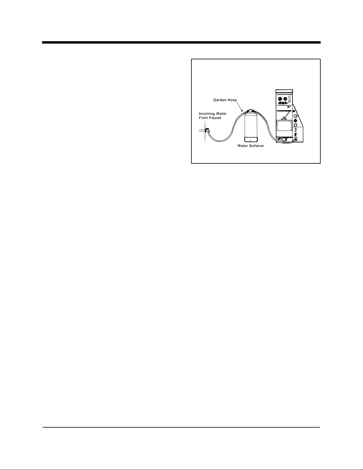
Contact a water softener distributor in
your area for information on the rental
of a simple water treatment unit to carry
in your truck. Be sure to change the
water softener in accordance with the
capability of the softener. For example:
If the softener will treat 900 gallons of
water and the machine uses an average of 30 gallons per hour, for an average of 5 hours a day, this equals 150
gallons per day. In 6 days the machine would use 900 gallons of water.
Therefore, the softener would need to be changed every 6 working days for
maximum softening.
Figure 1-1 Location of Water
Softener
WASTE WATER DISPOSAL ADVISORY
There are laws in most communities prohibiting the dumping of recovered gray
water from carpet cleaning in any place but a sanitary treatment system.
This cleaning rinse water, recovered into your units vacuum tank, contains
materials such as detergents. These must be processed before being safe for
streams, rivers and reservoirs.
IN ACCORDANCE WITH THE EPA, STATE AND LOCAL LAWS, DO NOT
DISPOSE OF WASTE WATER INTO GUTTERS, STORM DRAINS, STREAMS,
RESERVOIRS, ETC.
In most cases, an acceptable method of waste water disposal is to discharge
into a municipal sewage treatment system after first filtering out solid material
such as carpet fiber. Access to the sanitary system can be obtained through a
toilet, laundry drain, RV dump, etc. Permission should first be obtained from
any concerned party or agency. One disposal method which usually complies
HydraMaster Corporation
CDS 4.6
10/20/99
Page 24

Page 1-18 Clutch Drive System
with the law is to accumulate the waste water and haul it to an appropriate
dump site. Another solution to the disposal problem is to equip yourself with an
Automatic Pump-Out System. These systems are designed to remove waste
water from the extractors recovery system and actively pump the water through
hoses to a suitable disposal drain. Properly designed, they will continuously
monitor the level of waste water and pump it out simultaneously to the cleaning operation. The hidden benefit of this process is that the technician does not
have to stop his cleaning to empty the recovery tank. HydraMaster makes an
A.P.O. System available which can be ordered with new equipment or installed
later.
The penalties for non-compliance can be serious. Always check local laws and
regulations to be sure you are in compliance.
10/20/99
HydraMaster Corporation
CDS 4.6
Page 25

Clutch Drive System Page 1-19
Figure 1-2 Hard Water Map
HydraMaster Corporation
CDS 4.6
10/15/99
Page 26

Cleaning and Chemicals
CDS 4.6
Section 2-1
our mobile carpet cleaning plant has been engineered using the latest
Y
and most sophisticated technology available to produce the finest carpet
cleaning results possible. Despite this, however, it remains only a tool of the
carpet cleaning trade, and it can produce only as good a job as the person
operating it.
PRECAUTIONS
There are no short cuts to good carpet cleaning. It requires time, cleaning
knowledge and the use of good chemicals. Therefore, the manufacturer recommends the use of spotting agents and traffic lane cleaners, as required, prior
to the actual cleaning of carpeting.
The use of some chemicals through your mobile carpet cleaning plant can
seriously damage the internal plumbing, high pressure pump and heater.
These harmful chemicals include concentrated acid (see the pH chart at the
end of this section), solvents, and some paint, oil, and grease removers with
a high concentration of solvents.
The manufacturer recommends only the use of chemicals containing rust and
corrosion inhibitors and water softening agents to prevent chemical build-up
which may lead to component failure and warranty invalidation.
♦ CAUTION ♦
The increased demand for clear water rinsing results in the need for special
care when using these acid based chemicals in your equipment. The negative
side of these products is the corrosive effects the acid can have on metals,
including swivels, pumps, heat exchangers, etc.
HydraMaster Corporation
10/20/99
Page 27

Page 2-2 Clutch Drive System
HydraMasters ClearWater Rinse has been formulated to protect vital components. HydraMaster will not warranty parts that have been damaged from
using unprotected acid products that have obviously caused failures.
The use of detergents and chemicals which create foam when agitated should
be avoided. Foam passing through the blower could lead to serious problems.
HydraMaster and SafeClean chemicals are formulated with built in anti-foaming
agents. When cleaning surfaces with excessive foaming residue use HydraMaster Powder Defoam as directed.
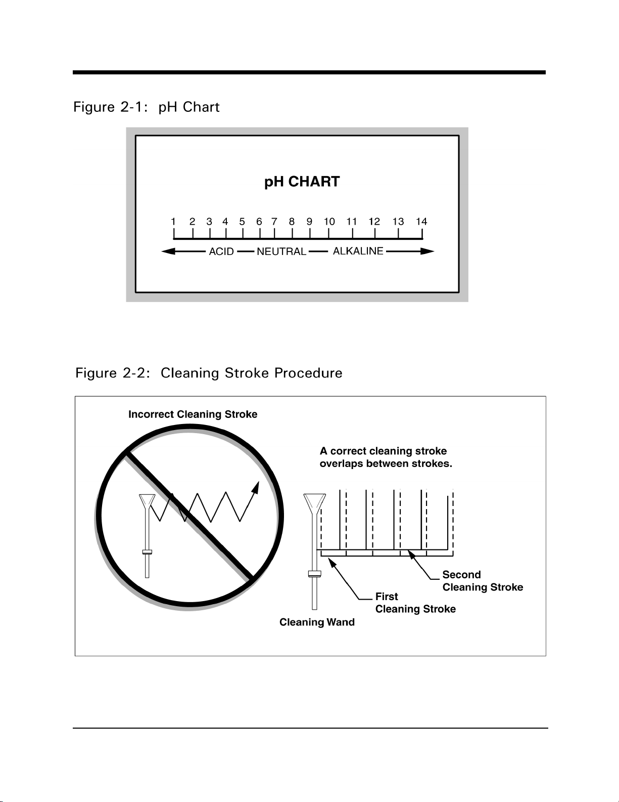
CLEANING STROKE PROCEDURE
Purpose:
To eliminate excess moisture remaining in the carpet fiber and the sawtooth
appearance which results from diagonal movement of the cleaning tool on all
types of carpet.
Procedure:
Always move the cleaning tool in smooth, forward and backward strokes.
Apply slight pressure to the forward stroke while the solution is injected into
the carpet. When extracting (drying), apply firm pressure on the forward stroke
to ensure a positive lock for the vacuum and minimize the hopping effect
resulting on carpet that is not smooth. During the forward and reverse strokes,
movement to the right or left should only be accomplished at the extreme rear
of the stroke. Overlapping is also important to ensure even application of
solution and prevent saturation when cleaning wand is stopped twice at the
same point at the rear of the cleaning stroke. This is illustrated at the end of
this section.
Failure to adopt this procedure can result in increased chance of clean streaks,
fiber shrinkage, brown-out and longer drying periods.
10/20/99
HydraMaster Corporation
CDS 4.6
Page 28

Clutch Drive System Page 2-3
OVER-WETTING
Over-wetting is annoying to all concerned, and sometimes leaves a bad impression of the cleaning process used.
These are Several Areas That Will Cause Over-wetting:
1. Too few vacuum strokes or improper saw-tooth vacuum strokes as shown
in the following illustration.
2. Obstructed, cut or kinked hoses.
3. Vacuum tank drain valve left partially open.
4. Clogged vacuum blower filter or vacuum tank lid not sealing properly.
5. Cleaning a heavily foam-saturated carpet without defoamer.
(We recommend crystal type.)
HydraMaster Corporation
CDS 4.6
10/20/99
Page 29
Page 2-4 Clutch Drive System
10/20/99
HydraMaster Corporation
CDS 4.6
Page 30

Operating Instructions
CDS 4.6
Section 3-1
BEFORE OPERATING THE UNIT
1. Operate the unit and equipment only in a well ventilated area.
♦ CAUTION ♦
Exhaust fumes contain carbon monoxide and may be hazardous to your health.
Do not operate this truck where the exhaust may enter any building doorway,
window, vent, or opening of any kind.
2. Check the fuel tank to be certain there is adequate fuel to complete
the job.
3. Position the wheel chocks on one of the front tires.
4. If using a water supply hose which has not been used recently or if
using a customers hose, first connect the hose to the faucet and flush
out any debris which may be in the hose. Afterwards connect the hose
the unit.
5. Check your chemical jug to see if you have enough concentrated
chemical to finish the job. If not, mix and fill a five gallon chemical jug.
6. Connect all required hoses.
7. When connecting the pressure hose to the pressure outlet connections
at the front of the unit, go to the farthest area to be cleaned and
connect to the cleaning tool. This insures that you have the proper
length of hose required to perform the cleaning.
HydraMaster Corporation
10/20/99
Page 31

Page 3-2 Clutch Drive System
START UP
1. Make sure the van gear select lever is in the Park position and
the emergency brake is set.
2. Start the van engine.
3. Turn key on CDS Dash. The RPM will automatically increase to
the proper running speed. Engine RPM should be as noted in the
Maintenance Section.
4. Pull the heat control valve open only if you will be using water.
Do not activate the heat exchanger during flood extraction work.
When the mix tank begins a fill cycle, the chemical flowmeter may
be adjusted to your desired setting. Set your cleaning pressure at
300 PSI.
NOTE: A chemical flowmeter set at 5 GPH is a 1 to 30 mix ratio
and 10 GPH is a 1 to 15 ratio.
5. Turn the APO switch ON if using the auto pump-out feature.
6. Now proceed with the cleaning operation.
NOTE: The machine will automatically shut down when it reaches
its full capacity due to the float switch located inside the
waste tank. When this occurs, turn the switch off and empty
the waste tank. Then turn the unit back on and continue to
clean.
10/20/99
HydraMaster Corporation
CDS 4.6
Page 32

Clutch Drive System Page 3-3
FLOOD DAMAGE WORK
When using equipment for flood damage, turn the cleaning water pressure
down to zero. This will reduce the engine power load and save on fuel consumption. Also, de-activate the heat exchangers to help prevent engine overheat problems.
SHUT DOWN
1. Shut off the knob on the chemical flowmeter. NOTE: If freeze guarding
is necessary, perform the freeze guard procedure at this time. Draining
the mix tank to ½ full or less is recommended to reduce spillage inside
the vehicle.
2. Open the mix tank drain and actuate the wand valve to run fresh water
through the chemical mix tank, heat exchangers and cleaning tools.
NOTE: Vinegar should be rinsed through the system weekly. De-scaler
should be rinsed through the entire system monthly.
3. Lay vacuum hoses out in order for all moisture to be removed from the
hoses. This prevents spillage of any dirty solution in your vehicle when
storing the hoses.
4. Disconnect the hoses and put them away.
5. If you are using an outside water source, turn the water supply faucet
off. Bleed pressure out of the supply hose by loosening the hose at the
water supply. Unhook the water supply hose and store it in the vehicle.
6. Allow the unit to run for a few minutes with the vacuum hose disconnected in order to remove all moisture from the vacuum pump. Next
plug the vacuum inlets. Spray lubricant into the lube port located on the
front panel above the pressure gauge while the unit is running.
HydraMaster Corporation
CDS 4.6
10/20/99
Page 33

Page 3-4 Clutch Drive System
Spray for about 5 to 10 seconds. This will lubricate the vacuum pump
and prevent it from rusting.
7. Remove the inlet plugs, then turn the machine off.
8. Before draining, it is recommended that the heat control knob be moved
to the OFF position. This will help to avoid potential engine overheat
problems due to reduced coolant flow through the radiator.
9. Drain the waste tank. Do not dump waste in any area which might
violate local, state or federal law. The pump-out system may be used
to drain the waste tank into a sanitary drain system. When the waste
tank is drained, lift waste tank lid and remove the filter screens. Clean
out any accumulated debris. Rinse. Re-install.
10/20/99
HydraMaster Corporation
CDS 4.6
Page 34

Freeze Guard
CDS 4.6
Section 4-1
ny freezing of this machine is not covered by warranty and during
A
the colder months of operation, careful protection should be of utmost
concern.
The following precautions are recommended prior to and during cleaning:
1. Run the machine before leaving for the first job to insure nothing has
frozen the night before, including hoses and wand.
2. Insulate the garden hose from the cold ground by running it through an
extra 1½ inch vacuum hose.
3. Leave truck doors closed until time cleaning begins, afterwards open
slightly.
4. In colder climates, insulating the truck walls and floor boards will help
protect the unit.
5. Do not procrastinate during the cleaning operation or the hot water
solution line will also freeze on the ground. The solution line should be
insulated in extremely cold climates.
6. Whenever possible, the truck should be stored in a heated garage at night
or over the weekend. If not possible, place a 1500 watt electric heater
inside the truck, aimed directly at the machine. Never use a propane
heater. It causes excessive moisture on the truck ceiling and the
possibility of it going out is higher. If the machine and truck are left
outside with a heater, you should drain water from the machine cleaning
tools and hoses. (They freeze also.)
HydraMaster Corporation
10/20/99
Page 35

Page 4-2 Clutch Drive System
To Drain the Machine, Follow These Steps:
A. Before shutting off the machine, remove the chemical line from the
chemical jug and place in a mixture of 50/50 antifreeze and water.
With the cleaning tool on, allow mixture to fill chemical system back
to the chemical mix tank.
B. Open the mix tank drain valve and allow the water to drain thoroughly
from the mix tank.
C. Close the mix tank drain and fill the mix tank with 50/50 antifreeze
and water mixture. Run the unit for 1 minute to circulate the mixture
through the machines low-pressure hoses. Spray through the wand
or other tool into a suitable container until the mix tank shut-off switch
activates (pump stops). This freeze guards the high-pressure circuit.
D. Open the mix tank drain and drain out the residual fluid into a suitable
container. This antifreeze solution may be retained for reuse (attach
freeze guard fitting to inlet quick connect and vacuum water out of the
inlet line).
♦ CAUTION ♦
One manufacturer of antifreeze cautions: WHEN DISPOSING OF USED ANTIFREEZE COOLANT: Follow local laws and regulations. If required, dispose at
facilities licensed to accept household hazardous waste. If permitted, dispose
in sanitary sewer systems. Do not discard into storm sewers, septic systems,
or onto the ground.
♦ WARNING ♦
This warning appears on the label of one brand of antifreeze: HARMFUL OR
FATAL IF SWALLOWED. Do not drink antifreeze coolant or solution. If
swallowed, induce vomiting immediately. Call a physician. Contains Ethylene
Glycol which caused birth defects in animal studies. Do not store in open or
unlabeled containers.
10/20/99
HydraMaster Corporation
CDS 4.6
Page 36

Clutch Drive System Page 4-3
KEEP OUT OF REACH OF CHILDREN AND ANIMALS.
BE SURE YOUR MACHINE IS PROTECTED!
Freezing will cause GRIEF, MONEY, and DOWN-TIME.
FREEZE PROTECTION OF THE PUMP-IN SYSTEM
1. Drain the fresh water tank.
2. Remove the garden hose adapter from the pump-in pump hose and
position the hose so it is pointing outside the van.
3. Turn on the pump-in pump and run for 1-2 minutes till all the water
is purged from the hose.
NOTE: The next time the unit is used it may take a few minutes before
the mix tank begins to fill.
HydraMaster Corporation
CDS 4.6
10/20/99
Page 37

Water and
Chemical System
CDS 4.6
Section 5-1
his electro-mechanical system has been designed to be simple and
T
trouble free.
WATER AND CHEMICAL FLOW OPERATION
Incoming water flows first through the solenoid control valve and the low pressure chemical injector which are both mounted on the exterior of the mix tank.
As the water passes through the chemical injector, it is automatically proportioned with a quantity of detergent that is adjusted with the flowmeter knob.
The mix tank is equipped with two different float switches, the water level float
responds to the level in the tank and will maintain the proper volume of solution
to be reserved for the water pump. The secondary, low water float switch is a
safety switch that is designed to protect your system from sudden or unexpected loss of water supply. If, for example, the water source at the house
were turned off, the water level of the mix tank would drop, activating the
secondary switch, which automatically disengages the system and prevents
the water pump from running dry.
The desired chemical injection ratio may be obtained by an adjustment of the
chemical flowmeter during the fill cycle of the mix tank. Water must be
flowing into the mix tank in order to adjust the chemical mix. The chemical will
flow from the chemical jug to the chemical flowmeter, then to the chemical
injector where it is proportioned into the mix tank at the desired chemical
setting.
HydraMaster Corporation
10/15/99
Page 38

Page 5-2 Clutch Drive System
NOTE: With this unique chemical system, the chemical flow is proportioned
only during the filling cycles of the mix tank, not during the direct spraying of
the wand. Therefore, it is possible that as your wand is spraying, you may
have no chemical flow. Also, the converse is true in that you may not be
spraying your wand, but if the mix tank is in a filling cycle, your chemical
flowmeter may be active at the desired flow rate.
The chemical proportioning system will mix chemical with water at a 1 to 30
ratio when the flowmeter is set at 5 GPH, or a 1 to 15 ratio when the flowmeter is set at 10 GPH.
CHEMICAL SYSTEM MAINTENANCE
The chemical lines may need to be flushed with vinegar periodically to prevent
abnormal chemical build-up. This flushing may be done by removing the clear
plastic hose from the chemical jug and inserting it into a one quart container of
vinegar. This should be done with the chemical flowmeter setting 10 GPH.
Simply spray water from the wand until the quart of vinegar is exhausted.
Then repeat the process with one quart of clear water to void all lines of
vinegar.
10/20/99
HydraMaster Corporation
CDS 4.6
Page 39

Clutch Drive System Page 5-3
Figure 5-1 Water Flow Diagram
D4497 Rev A
HydraMaster Corporation
CDS 4.6
9/5/00
Page 40

Page 5-4 Clutch Drive System
Figure 5-2 Proportioner Diagram
10/20/99
HydraMaster Corporation
CDS 4.6
Page 41

Clutch Drive System Page 5-5
Chemical Tank
Troubleshooting
HydraMaster Corporation
CDS 4.6
10/20/99
Page 42

Page 5-6 Clutch Drive System
10/20/99
HydraMaster Corporation
CDS 4.6
Page 43

Pump Maintenance
CDS 4.6
Section 6-1
DAILY
1. Check the oil level and the condition of the oil. The oil level
should be up to the center of the sight glass on the back of the
pump.
Use a 30 weight, non-detergent oil.
♦ CAUTION ♦
If the oil becomes discolored and contaminated, one of the oil seals may be
damaged. Refer to the Service Section.
Do not operate the pump if the crankcase has been contaminated with water.
♦ CAUTION ♦
Do not leave contaminated oil in the pump housing or leave the housing empty.
Remove contaminated oil as soon as it is discovered and replace it with clean
oil.
PERIODICALLY
1. Change the oil after the first 100 hours of operation, and every
400 operating hours thereafter. When changing, remove the
drain plug on the oil drain hose so all oil and accumulated
sediment will drain out.
HydraMaster Corporation
10/20/99
Page 44

Page 6-2 Clutch Drive System
♦ CAUTION ♦
Do not turn the drive shaft while the oil reservoir is empty.
♦ CAUTION ♦
Protect the pump from freezing.
10/20/99
HydraMaster Corporation
CDS 4.6
Page 45

Clutch Drive System Page 6-3
Pump Service
he next few pages explain how to disassemble and inspect all easily
serviceable parts of the pump.
T
♦ CAUTION ♦
Do not disassemble the hydraulic end unless you are a skilled mechanic. For
assistance, contact HydraMaster (425-775-7275) or the distributor in your area.
1.0 Servicing the Valves (See illustrations above.)
A.Remove the hex valve plugs (top-discharge, bottom-inlet).
B. Unthread the valve plug and examine the o-ring under the plug for cuts or
distortion. Replace it if it is worn. Lubricate new o-rings before installing.
C. Grasp the valve retainer by the tab at the top with needle-nose pliers,
then remove the o-ring at the bottom of the valve chamber.
D. Inspect all valve parts for pitting, gouges, or wear. If wear is excessive,
replace valve assembly.
E. Reinstall valve assemblies:
1. Using a clean towel, clean the valve chamber.
HydraMaster Corporation
CDS 4.6
10/20/99
Page 46

Page 6-4 Clutch Drive System
2. Install the o-ring into the high pressure manifold.
3. Install the valve assemblies into the high pressure manifold
(the metal side of the valve faces the manifold).
4. Replace the o-ring on the hex valve plug.
5. Torque the plug to 72 foot pounds.
2.0 Removing the High Pressure Manifold
A. Using an M6 allen wrench, remove all eight of the socket head bolts.
B. Rotate the crankshaft by hand to start separation of the manifold head
from the crankshaft.
C. Insert two flat-head screwdrivers on opposite sides to further separate
the manifold from the crankshaft.
♦ CAUTION ♦
To avoid damage to either plunger or seal, keep the manifold properly aligned
with the ceramic plungers when removing it.
D. Remove the seal retainer from the manifold and inspect for wear.
E. Examine the ceramic plunger for cracks or scoring (refer to Servicing the
Plungers for replacement).
3.0 Servicing the Low Pressure Seals and High Pressure Seals
(See illustrations above.)
A. Remove the low pressure seal from the seal retainer using a 90 degree
pick tool.
10/20/99
HydraMaster Corporation
CDS 4.6
Page 47

Clutch Drive System Page 6-5
B. Remove the high pressure seal from the manifold.
C. Inspect the low pressure seal and high pressure seal for wear and replace
if necessary.
D. Reinstall the low pressure seal:
1. Install the low pressure seal into the seal retainers with the garter
spring down.
E. Reinstall the high pressure seal:
1. Lubricate the seal chamber in the manifold.
2. Carefully square the high pressure seal into position by hand with the
grooved side down (metal back facing out).
3. Examine the seal retainers o-ring and replace if worn. Lubricate the
new o-ring before installing.
4. Next, press the seal retainers into the manifold until completely seated.
4.0 Servicing the Plungers (See illustrations above Step 3.)
A. Using a hex tool, loosen the plunger retainer about three to four turns.
Push the plunger back to separate it from the retainer and finish unthreading
the plunger retainer by hand.
B. Unthread the plunger retainer with sealing washer.
C. Remove the ceramic plunger, keyhole washer and barrier slinger from the
plunger rod.
D. Reinstall the ceramic plungers:
1. Examine the sealing washer on the plunger retainer and replace it if it
is cut or worn. Lubricate the new sealing washer for ease of installation and to avoid damage.
2. Apply Loctite 242 to the threads of the plunger retainer and press it
into the ceramic plunger. Thread hand tight, then torque the bolt to
4.4 foot pounds.
3. Install the seal retainer with holes to the top and bottom, and forward.
HydraMaster Corporation
CDS 4.6
10/20/99
Page 48

Page 6-6 Clutch Drive System
5.0 Reinstall High Pressure Manifold
A. Slip the seal retainer over the ceramic plungers with the holes to the top
and bottom and forward.
B. Turn the shaft by hand to line up the plungers so that the end plungers
are parallel.
C. Lightly lubricate the plungers and carefully slide the manifold head onto
the plungers while supporting it from the underside to avoid damaging
the plungers.
D. Reinstall the socket head bolts and torque to 4.4 foot pounds.
6.0 Servicing the Crankcase
A. While manifold, plungers, and seal retainers are removed, examine the
crankcase seals for wear.
B. Rotate the crankshaft oil seal externally for drying, cracking or leaking.
C. Consult your HydraMaster distributor if crankcase servicing is
necessary.
Torque Chart
Torque
Pump Item Thread Inch Pounds Foot Pounds Nm
Plunger Retainer M6 55 4.4 6.2
Manifold Bolt M6 55 4.4 6.2
Valve Plugs M22 870 72.3 100.0
Bearing Case Screws M6 50 4.0 6.0
Crankcase Cover M6 50 4.0 6.0
Bubble Oil Gauge M28 45 3.6 5.0
Mounting Bolts M8 115 9.4 13.0
10/20/99
HydraMaster Corporation
CDS 4.6
Page 49

Clutch Drive System Page 6-7
Figure 6-3 Cat Pump
HydraMaster Corporation
CDS 4.6
10/20/99
Page 50

Page 6-8 Clutch Drive System
Cat Pump Parts List
ITEM PART NO. DESCRIPTION QTY
2 30057 Key (M6) 1
5 96031 Screw, Sems HHC, Bearing Cover (M8x16) 8
8 46910 Cover, Bearing 2
10 14028 O-Ring, Bearing Cover 1
11 43222 Seal, Oil, Crankshaft 2
15 14480 Bearing
20 46743 Rod, Connecting, Assembly 2
25 46928 Crankshaft, Dual End 3
32 46798 Cap, Oil Filler 1
33 14179 O-Ring, Oil Filler Cap 1
37 43987 Gauge, Oil, Bubble 1
38 44428 Gasket, Flat, Oil Gauge 1
40 92519 Screw, Sems HHC, Crankcase Cover (M6x16) 4
1
48 25625 Plug, Drain (
49 23170 O-Ring, Drain Plug 1
50 46940 Cover, Crankcase 1
51 14044 O-Ring, Crankcase Cover 1
53 46912 Crankcase 1
64 46746 Pin, Plunger Rod 3
65 46747 Rod, Plunger 3
70 147-013 Seal, Crankcase Oil for 3CP Cat Pump 3
75 43900 Slinger, Barrier 3
88 45697 Washer, Keyhole 3
90 46893 Plunger (M50) 3
/4 x 11) 1
98 46730 Seal, Washer 3
99 46729 Retainer, Plunger with Stud (M7) 3
100 46749 Retainer, Seal 3
10/20/99
HydraMaster Corporation
CDS 4.6
Page 51

Clutch Drive System Page 6-9
ITEM PART NO. DESCRIPTION QTY
106 43243 Seal, LPS with Spring 3
120 46896 Case, Seal
121 13976 O-Ring, Seal case 3
127 44549 V Packing 6
128 44548 Adapter, Male 3
139 22179 Plug, Inlet ½ 1
163 17547 O-Ring 85, Valve Seat 6
164 46658 Seat 6
166 46429 Valve 6
167 43750 Spring 6
168 46583 Retainer, Spring 6
172 17549 O-Ring, Valve Plug 6
173 48365 Back up Ring, Valve Plug 6
174 45900 Plug, Valve 6
185 46895 Manifold, Head 1
193 87872 Bolt, HSH, Manifold Head (M8x70) 8
196 22187 Plug, Discharge
129 814843 Complete Head 1
300 078-271 Kit, Seal for 3CP Cat Pump 1
310 078-270 Kit, Valve for 3CP Cat Pump 1
350 30696 Valve Seal Removal Tool 1
3
/81
HydraMaster Corporation
CDS 4.6
10/20/99
Page 52

Page 6-10 Clutch Drive System
Pump Troubleshooting
Cavitation
l Inadequate fluid supply because of:
-Inlet line collapsed or clogged.
-Air leak in inlet line.
-Worn or damaged inlet hose.
l Fluid too hot for inlet suction piping system.
l Air entrained in fluid piping system.
l Aeration and turbulence in supply tank.
l High pressure seals worn.
Symptoms of Cavitation:
l Excessive pump valve noise (chattering)
l Premature failure of spring or retainer
l Volume or pressure drop
l Rough-running pump.
Drop in Volume or Pressure
l Air leak in suction piping.
l Clogged suction line.
l Pressure gauge inoperative or not registering accurate.
l Suction line inlet above fluid level in tank.
l Inadequate fluid supply.
l Pump not operating at proper RPM.
l Worn pump valve parts.
l Foreign material in inlet or outlet valves.
l Worn low pressure seals.
l Cavitation.
l Belt slippage.
10/20/99
HydraMaster Corporation
CDS 4.6
Page 53

Clutch Drive System Page 6-11
Water Pulsations
l Foreign object lodged in pump valve.
l Air in suction line.
l Valve spring broken.
l Cavitation.
l Aeration or turbulence in supply tank.
l Stuck inlet or discharge valve.
Valve Wear
l Normal wear.
Loss of Oil
l External seepage.
l Frozen pump.
l Worn crankshaft seal.
l Oil drain piping or fill cap loose.
Premature Failure of Valves or Seals
l Excessive cavitation.
l Foreign object in the pump.
l Pump running too fast.
l Valve or seal material incompatible with fluid being pumped.
l Excessive inlet pressure.
l Scored plungers.
l Running pump dry for excessive periods of time.
l Excessive temperatures of fluid being pumped.
HydraMaster Corporation
CDS 4.6
10/20/99
Page 54

Machine Assemblies
CDS 4.6
Section 7-1
Figure 7-1 CDS 4.6 Machine Assembly
D4429 Sht 1, Rev A
and Parts Lists
HydraMaster Corporation
10/20/99
Page 55

Page 7-2 Clutch Drive System
Figure 7-2 CDS 4.6 Machine Assembly-Rear View
D4429 Sht 2, Rev A
10/20/99
HydraMaster Corporation
CDS 4.6
Page 56

Clutch Drive System Page 7-3
Figure 7-3 CDS 4.6 Machine Assembly-Top and Front Views
D4429 Sht 3 & 4, Rev A
HydraMaster Corporation
CDS 4.6
10/20/99
Page 57

Page 7-4 Clutch Drive System
Figure 7-4: Recovery Tank Assembly - Front View
D4430 Sht 1, Rev
10/20/99
HydraMaster Corporation
CDS 4.6
Page 58

Clutch Drive System Page 7-5
Figure 7-5 Recovery Tank Assembly-Rear View
D4430 Sht 1, Rev
HydraMaster Corporation
CDS 4.6
10/20/99
Page 59

Page 7-6 Clutch Drive System
Recovery Tank Assembly Parts List
REF. NO. PART NO. DESCRIPTION QTY
1 159-031 Recovery Tank 1
2 Dash Box Assembly 1
3 Instrument Panel Assembly 1
4 Mix Tank Assembly 1
5 Dual Heat Exchanger Assembly 1
6 Cover Assembly, Recovery Tank 1
7 166-002 Soap Jug Tray 1
8 601-013-001 Instrument Panel to Vacuum Tank Stabilizer 1
9 105-011 Plate, Filter Bag Support 1
10 068-152 Hose Assembly, Mix Tank Control Panel 2
11 068-150 Hose Assembly, Bypass 1
3
12 068-089 Hose Assembly,
13 068-094 Hose Assembly,
14 068-025 Hose, 1.4 Clear A/R
5
15 068-030 Hose,
/
Vacuum A/R
32
16 063-007 Harness, CDS Wire-Primary 1
/
x24 Lg Teflon 1
8
3
/
x16 Lg. Teflon 1
8
17 063-008 Wire Harness Wrap, Split Seam A/R
18 081-070 Label, Small CAUTION 1
1
19 033-021 Clamp,
20 033-023 Clamp,
/
Nylon Hose 3
4
3
/
Nylon Hose 5
4
21 049-013 Filter, Vacuum Pump Blower 1
22 159-016 Jug, 5 Gallon Chemical 1
23 052-182 Nipple, 1.50 NPT Close Galvinized 1
24 125-111 Pipe, Vacuum Relief Spring Guide 1
25 155-026 Spring, Vacuum Relief 1
26 157-012 Switch, Heavy Duty Liquid Level Float 1
3
27 131-027 Trimlok, Crossfire Brow Trim
28 131-028 Trimlok, Recovery Tank Gasket
3
29 131-003 Trimlok, CDS Trim
/
A/R
4
/
A/R
8
3
/
A/R
4
30 169-022 Valve, 1.50 NPT Full Port 1
10/20/99
HydraMaster Corporation
CDS 4.6
Page 60

Clutch Drive System Page 7-7
Recovery Tank Assembly Parts List
REF. NO. PART NO. DESCRIPTION QTY
31 143-114 Flat Head Machine Screw,
#10-24UNC x 0.50 LG. 1
32 143-132 Hex Head Machine Screw 2
#10-24UNC x 0.75 LG.
33 143-064 Flat Head Machine Screw, 5
#10-24UNC x 1.00 LG
34 143-115 Hex Head Machine Screw, 2
1
/
-20UNC x 0.75 LG
4
35 143-198 Hex Head Machine Screw,
3
/
-16UNC x 4 LG. 1
8
36 143-143 Hex Head Machine Screw,
5
/
18UNC x 1.00 LG 2
16
37 094-004 Hex Nut, #10-24UNC 11
38 094-034 Hex Nut, #10-24UNC Nylock 2
3
39 094-077 Nut,
/
-18UNC x
8
1.00 O.D. Knurled 2
1
40 094-007 Whiz Nut,
41 094-023 Whiz Nut,
/
-20UNC 2
4
5
/
-18UNC 2
16
42 174-015 Washer, #10 Outside Star 11
43 174-001 Washer, #10 Flat 1
1
44 174-003 Washer,
/
Flat 4
4
45 052-360 Adapter, 3 FPT x 3 M Slip 1
46 052-361 Elbow, 3 F Slip x 3 M Slip 1
47 015-182 Bracket, Vacuum Relief Valve 1
48 027-031 Cap, Vacuum Relief 1
49 081-056 Label, H/M Lubrication Schedule 1
50 103-028 Locking Pin Assembly 1
3
51 174-032 Washer,
/
Flat 1
8
52 143-126 Hex Head Machine Screw
#10-24UNC x 0.50 LG. 1
HydraMaster Corporation
CDS 4.6
10/20/99
Page 61

Page 7-8 Clutch Drive System
Figure 7-6 Recovery Tank Lid Assembly
D4456, Rev
REF. NO. PART NO. DESCRIPTION QTY
1 052-219 Adapter, 2NPT x 2 S Slip 2
2 052-404 Adapter, 3 F Slip x 2 F Slip 2
3 041-228 Cover, Recovery Tank-Painted 1
4 052-222 Elbow, 2 Barb x 2 FPT 2
5 049-030 Filter Bag 2
1
6 052-015 Gasket, 17 125-052 Tube, 2x1.5 Lg. Filter Bag
Adapter Sleeve 2
8 078-039 Vacuum Inlet Stopper Assembly 1
9 143-158 Button Head Machine Screw
#10-25UNC x .63 Lg 1
10/20/99
/
Bulkhead Fitting 2
2
HydraMaster Corporation
CDS 4.6
Page 62

Clutch Drive System Page 7-9
Figure 7-7 Instrument Panel Assembly
D4149, Rev B
HydraMaster Corporation
CDS 4.6
10/20/99
Page 63

Page 7-10 Clutch Drive System
Instrument Panel Assembly Parts List
REF. NO. PART NO. DESCRIPTION QTY
1 052-010 4FA-2UFS 1
2
3 052-019 6M-6UFS 5
3
4 052-060
/
NPT x
8
5 025-002 Choke 3 Cable 1
6 027-014 Garden Hose Cap 1
7 052-272 Gravity Feed Oil Blower
Lubrication Port Cup 1
3
8 052-086
/
NPT Street Elbow 1
8
9 131-003 CDS Trim ¾ Gasket 4
10 057-055 Garden Hose Gasket 1
11 074-003 HI PSI (0-1000) Gauge 1
1
/
NPT Bushing 1
8
12 060-002 Large Wiring Grommet 1
13 090-008 High Pressure Manifold 1
3
14 068-285
/
x 8.5 Lg Teflon Hose Assembly 1
16
15 052-096 No. F23 Insert 1
16 052-487 No. 24 Modified Insert 1
17 052-097 No. 24 Insert 2
18 052-104 No. 66 Insert 1
19 052-338 No. 1212 Insert 1
20 074-020 Chemical Flow Meter 1
21 052-071 ¼ NPT Hex Nipple 2
22 052-281 ¾ NPT x ¾ M Garden Hose Nipple 1
23 100-173 Instrument Panel 1
24 105-012 Machine Serial I.D. Plate 1
25 106-029 1 Hole Plug 1
26 052-050 440 Male Quick Connect 2
27 052-052 660 Male Quick Connect 1
28 135-052 Hi PSI Snubber Regulator 1
1
29 140-015 1
/
x ¼ LG Pop Rivet 2
8
10/20/99
HydraMaster Corporation
CDS 4.6
Page 64

Clutch Drive System Page 7-11
Instrument Panel Assembly Parts List
REF. NO. PART NO. DESCRIPTION QTY
30 149-039 Water Temperature Sender 1
3
31 052-023
32 169-064
33 169-009 ¾ FPT Swing Check Valve 1
34 169-101 By-Pass Valve 1
35 174-005
36 174-040
37 174-040
38 174-050 1 Flat Washer 1
39 081-099 Label Set 1
40 105-020 HydraMaster Cast Name Plate 1
41 139-023 Push-on Retainer Ring 2
/
NPT Male Street Tee 1
8
3
/
NPT Full Port Ball Valve 1
8
3
/
Flat Washer 1
8
9
/
Flat Washer 4
16
5
/
Flat Washer 4
8
HydraMaster Corporation
CDS 4.6
10/20/99
Page 65

Page 7-12 Clutch Drive System
Figure 7-8 Dual Heat Exchanger Assembly
D3803, Rev B
10/20/99
HydraMaster Corporation
CDS 4.6
Page 66

Clutch Drive System Page 7-13
Dual Heat Exchanger Assembly Parts List
ITEM PART NO DESCRIPTION QTY
1 038-011 Heat Exchanger Core 2
2 015-171 Bracket, Dual Heat
Exchanger Mounting-R/H 1
3 015-172 Bracket, Dual Heat
Exchanger Mounting-l/H 1
4 052-477 Elbow, Heat Exchanger Connector 2
5
6 068-071 Hose Assembly, 3/8 x 12 Lg 1
7 068-087 1 X 1.5 Lg Red Hose 1
8
9 052-033 8MA-6UFS 2
10 052-064 1/2 NPT x 3/8 FPT Bushing 2
11 052-259 3/4 NPT x 3/8 FPT Bushing 1
12 033-020 No. 16 Hose Clamp 2
13 052-086 3/8 NPT Street Elbow 2
14 052-340 3/4 NPT Street Elbow 1
15 052-338 No. 1212 Insert 2
16 131-042 4.13 I.D. x .50 Wall x 33 Lg
Insulation 1
17 052-330 3/4 NPT Hex Nipple 1
18 149-021 Hi Temp Limit 218° F Sensor 1
19 052-447 3/8 NPT Male Branch Tee 1
20 052-336 3/4FPT x FPT x FPT Tee 1
21 162-006 15.5 Lg Tie Wrap 6
22 143-115 Lg Hex Head Machine Screw
1/420UNC x 3/4 8
23 174-019 1/4 Lock Washer 8
HydraMaster Corporation
CDS 4.6
10/20/99
Page 67

Page 7-14 Clutch Drive System
Figure 7-9 Salsa X Assembly
D4801 Rev C
9/5/00
HydraMaster Corporation
CDS 4.6
Page 68

Clutch Drive System Page 7-15
Salsa X Assembly Parts List
ITEM PART NO DESCRIPTION QTY
1 052-528 Nipple,
3
/
M JIC x
8
3
/
NPT 4
8
2 169-172 Valve, 3-Way 3/8 NPT 1
3
3 052-086 Elbow,
4 052-023 Tee,
5 068-245 Hose,
6 052-064 Bushing, ½ x
/
NPT Street 3
8
3
/
NPT Male Street 3
8
3
/
x 12 Teflon 1
8
3
/
FPT 2
8
7 169-027 Valve, Thermal Relief 1
3
8 068-257 Hose,
9 068-017 Hose,
10 052-586 Nipple,
/
Teflon x 24 1
16
3
/
x 32 1
8
1
/
FPT x ¼ SAE 1
8
11 052-585 Nipple, Tee Jet Modified 1
12 094-028 Nut, Brass Jet Assembly 1
13 052-153 Housing, Stabilizer Nozzle 1
14 049-052 Filter Cartridge, ¼ 1
15 180-007 Orifice, Salsa X 1
16 052-104 Insert #66 1
17 033-004 Clamp, Size 6 2
18 052-099 Insert #26 1
19 108-111 Protector, Insulation Blanket, Salsa X x 36 1
20 038-052 Core Assembly, Salsa X 1
21 052-669 Coupler, ½ FPT 2
22 052-675 Elbow, 3 Steel Modified 1
23 052-674 Elbow, 3 Rubber Assembly 2
24 068-617 Hose, 3 Silicone x 7 Assembly 1
25 068-616 Hose, 3: Nitrile x 9 Assembly 1
3
26 052-061 Bushing,
27 052-172 Insert, ¼ NPT x
28 068-618 Hose,
/
NPT x ¼ FPT 1
8
3
/
Hose 1
16
3
/
x 19 Teflon 2
8
29 001-094 Adapter, Blower to Salsa X 1
HydraMaster Corporation
CDS 4.6
9/5/00
Page 69

Page 7-16 Clutch Drive System
Figure 7-10 CDS 4.6 Pump and Blower Assembly
D4431, Rev B
9/5/00
HydraMaster Corporation
CDS 4.6
Page 70

Clutch Drive System Page 7-17
Pump and Blower Assembly Parts List
ITEM PART NO DESCRIPTION QTY
1 001-041 Adapter, Blower Inlet 1
2 001-042 Adapter, Blower Outlet 1
3 015-173 Bracket, Cat Pump Tensioner Plate 1
4 015-174 Bracket, Hose Holding 1
5 Drive Shaft Assembly 1
6 055-037 Frame, Pump and Blower 1
7 108-061 Protector, Cat Pump Belt Guard 1
8 108-060 Protector, Cat Pump Head 1
9 150-040 Shaft, Drive Sprocket 1
10 052-019 6M-6UFS 1
11 052-038 8M-UFS 1
12 010-052 Belt, Polychain GT Blower Drive 1
13 010-012 Belt, Pump Drive Gates #9325 1
14 111-012 Blower, 4.2 Hydra Whisper 1
7
15 020-019 Bushing, #H x
16 020-036 Bushing, SDS 117 052-062 Bushing, ¼ NPT x
3
18 020-001 Bushing,
/
/
1
8
1
/
1
8
3
/
FPT 1
8
Vac Pump Hub 1
8
19 033-023 Clamp, ¾ Hose 1
3
20 052-079 Cross,
21 052-084 Elbow,
/
FPT 1
8
3
/
NPT Street 1
8
22 052-085 Elbow, ¼ Street 2
3
23 052-086 Elbow,
/
NPT Street 1
8
24 052-087 Elbow, ½ NPT Street 1
25 068-149 Hose Assembly, CDS Blower Oil Drain 2
26 052-293 Insert, #23 3
27 077-001 Key, #3 and #4 Vacuum Pump Drive 4
28 077-006 Key, Blower Drive x ¼ 1
29 Magnet, Tachometer Sensor 2
3
30 052-057 Nipple,
/
” NPT Close 1
8
HydraMaster Corporation
CDS 4.6
9/5/00
Page 71

Page 7-18 Clutch Drive System
Pump and Blower Assembly Parts List
ITEM PART NO DESCRIPTION QTY
3
31 088-020 Pillow Block Bearing, 132 Tachometer Sensor/Bracket Assembly 1
3
33 106-003 Plug,
/
NPT 1
8
34 106-004 Plug, ½ NPT 1
35 109-022 Pulley, #AK 54 H 1
7
36 109-009 Pulley, 2¾ x
/
Pump
8
Drive-Modified 1
37 109-055 Pulley, 40 Tooth Sprocket Poly Chain 1
38 109-056 Pulley, 56 Tooth Sprocket Poly Chain 1
39 109-042 Pulley, 5 Pump 1
40 108-055 Protector, 3CP Cat Pump Shaft 1
/
Bore 2
16
41 111-070 Pump, 4GPM Cat Hi Temp, Plunger 1
42 114-003 Pail, Angle, 3CP Cat Pump (Set) 1
43 139-021 Snap Ring, 1¾ I.D. Drive Shaft 2
1
44 052-505 Zerk Grease Fitting,
/
NPT Straight 4
8
45 143-126 Hex Head Machine Screw,
#1020UNC x 0,50 Lg. 1
46 143-115 Hex Head Machine Screw,
¼20UNC x 0.74 Lg. 1
47 143-002 Hex Head Machine Screw,
¼20UNC x 1.00 Lg. 2
48 143-148 Hex Head Machine Screw,
5
/
18UNC x 0.50 Lg. 4
16
49 143-013 Hex Head Machine Screw,
5
/
18UNC x 1.00 Lg. 1
16
50 143-016 Hex Head Machine Screw,
5
/
18UNC x 2.50 Lg. 2
16
51 143-094 Socket Head Machine Screw,
3
/
16UNC x 0.75 Lg. 4
8
52 143-096 Hex Head Machine Screw,
3
/
16UNC x 1.00 Lg. 5
8
9/5/00
HydraMaster Corporation
CDS 4.6
Page 72

Clutch Drive System Page 7-19
Pump and Blower Assembly Parts List
ITEM PART NO DESCRIPTION QTY
53 143-260 Hex Head Machine Screw,
3
/
16UNC x 8.00 Lg. 1
8
54 143-240 Hex Head Machine Screw,
½13UNC x 1.75 Lg. Grade 5 5
5
55 094-012 Nut,
56 094-015 Nut,
57 094-016 Nut,
58 094-020 Nut, ½13UNC Whiz 4
59 174-001 Washer, #10 Flat 1
60 174-017 Washer, ¼ Lock 1
61 174-004 Washer,
62 174-020 Washer,
63 174-018 Washer,
64 174-032 Washer,
65 174-057 Washer,
66 174-007 Washer, ½ Flat 4
/
18UNC Hex 2
16
3
/
16UNC, Two-Way Locking 1
8
3
/
16UNC Whiz 2
8
5
/
Flat 1
16
5
/
Cam Lock 4
16
5
/
Lock 2
16
3
/
Flat 1
8
3
/
Lock 4
8
HydraMaster Corporation
CDS 4.6
9/5/00
Page 73

Page 7-20 Clutch Drive System
Figure 7-11 Dash Box Assembly
C2712, C3466, Rev B
ITEM PART NO DESCRIPTION QTY
1 013-006 Box, CDS Dash 1
2 Figure 7-11 Dash Panel Assembly 1
4 060-002 Grommet, Large Wiring 1
5 131-003 Gasket, CDS Trim 45
1
6 143-114 Screw, 1024 x
/
FHM Phillips s/s 8
2
7 094-034 Nut, 10-24 s/s Nylock 8
1
8 169-062 Valve,
9 068-025 Hose,
10 068-025 Hose,
/
Anti-Siphon 1
4
1
/
Clear 30
4
1
/
Clear 30
4
Not Shown:
178-090 Wire Assembly, Vanguard High
Temp. Switch 1
9/5/00
HydraMaster Corporation
CDS 4.6
Page 74

Clutch Drive System Page 7-21
Figure 7-12 Dash Panel Assembly
C3465, Rev B
ITEM PART NO DESCRIPTION QTY
1 018-004 25 AMP Circuit Breaker 1
2 100-071 Painted Dash Panel 1
3 074-019 Engine Tachometer Gauge 1
4 074-018 Rectangular Hour Meter Gauge 1
5 074-016 Temperature Gauge 1
6 074-006 Vacuum Gauge 1
7 084-015 12V, 2W Round Red Indicator Lamp 5
8 084-004 Replacement Gauge Lamp 3
9 084-009 Socket-Dashboard Lamp 3
10 157-040 20 AMP Rocker Switch 3
11 157-008 Ignition Switch 1
12 033-049 Indicator Light Clamp 5
1
13 052-084
/
NPT Street Elbow 1
8
14 052-096 No. F23 Insert 1
1
15 174-052
/
Flat Washer 1
8
HydraMaster Corporation
CDS 4.6
10/20/99
Page 75

Page 7-22 Clutch Drive System
Figure 7-13 Mix Tank Assembly
D4457, Rev A
9/5/00
HydraMaster Corporation
CDS 4.6
Page 76

Clutch Drive System Page 7-23
Mix Tank Assembly Parts List
ITEM PART NO DESCRIPTION QTY
1 159-032 Tank, CDS Chemical Mix 1
2 041-038 Cover, CDS Chemical Mix Tank 1
3 Part Deleted 4 169-120 Valve, Chemical System Solenoid - 12 Volt 1
5 157-012 Switch, Side Mount w/ Bulkhead Fitting 2
6 Part Deleted 7 Part Deleted -
1
8 068-327 Hose,
9 181-008 Venturi, Low Pressure Injector-Modified 1
10 052-074 Nipple,
11 052-086 Elbow,
12 052-026 6FA-6UFS 1
13 052-142 Elbow,
14 052-105 Insert, #68 1
15 052-087 Elbow,
16 131-027 Trimlok, 12.75 Lg. CrossFire Brow 1
/
x 69.5 Lg. Clear Braid 1
2
3
/
NPT Hex 1
8
3
/
NPT Street 2
8
3
/
NPT Female 1
8
1
/
NPT Street 1
2
17 Part Deleted 18 Part Deleted 19 Part Deleted 20 Part Deleted -
HydraMaster Corporation
CDS 4.6
9/5/00
Page 77

Page 7-24 Clutch Drive System
Figure 7-14 Tachometer Sensor and Bracket Assembly
B3237, Rev
ITEM PART NO DESCRIPTION QTY
1 015-060 Bracket, CDS Tachometer Magnet Extension1
2 149-010 Sensor, CDS Magnet Tachometer
(only parts shown are used here) 1
3
3 037-017 Terminal,
Vinyl Insulated 1
4 037-012 Terminal, Fully Insulated Female QC 1
9/5/00
/
Stud, 10GA Wire,
8
HydraMaster Corporation
CDS 4.6
Page 78

Clutch Drive System Page 7-25
Figure 7-15 Horizontal Pump in Tank Assembly
D3700, Rev A
HydraMaster Corporation
CDS 4.6
9/5/00
Page 79

Page 7-26 Clutch Drive System
Horizontal Pump in Tank Assembly Parts List
ITEM PART NO DESCRIPTION QTY
1 159-005 Tank, 120 Gallon Horizontal 1
2 033-004 Clamp, #6 Mini Hose 2
3 041-005 Cover, 6" Pump-In Tank 2
4 052-086 Elbow, = Brass Street 1
5 052-143 Elbow, ½ F x F Brass 1
6 049-006 Filter, ½ Inline Y - Cat Pump 1
7 068-025 Hose, ¼ Clear 9I
8 068-327 Hose, ½ Clear Braid 6½
9 068-165 Hose, Pump-In Overflow 1
10 052-103 Insert, #64 2
11 052-107 Insert, #88 1
12 052-313 Insert, ½ Plastic Swivel Straight 2
13 052-226 Insert, 1½ NPT x 1½ Barb 1
14 081-173 Label, HydraMaster Accessory 1
15 052-074 Nipple, = Brass Hex 1
16 052-076 Nipple, ½ Brass Hex 2
17 052-182 Nipple, 1½ Close - Galv. Steel 1
18 111-010 Pump, 35 PSI Elect. Pump-In with M Threads 1
19 052-052 Quick Connect, 660 Male with Viton 1
20 052-023 Tee, ? Male Street - Brass 1
21 169-022 Valve, 1½ Full Port Brass Dump 1
22 143-114 Screw, 10-24 x ½ FHM Phillips s/s 12
23 143-113 Screw, 10-24 x 1½ FHM s/s 4
24 094-034 Nut, 10-24 s/s Nylock 4
25 174-001 Washer, #10 s/s Flat 4
26 166-012 Tray, Air Mover - Removable 2
27 166-014 Tray, 4-Bin Storage - Removable 1
28 083-002 Leg, Tray Support 2
29 143-019 Screw, =- 16 x 1¼ HHC Grade 5 Zinc 16
30 094-014 Nut, = - 16 Hex 16
31 174-005 Washer, = Flat 32
32 174-021 Washer, Lock 16
9/5/00
HydraMaster Corporation
CDS 4.6
Page 80

Clutch Drive System Page 7-27
Figure 7-16 Vacuum Relief Valve Assembly
C4237, Rev
ITEM PART NO DESCRIPTION QTY
1 015-182 Bracket, Vacuum Relief 1
2 027-031 Cap, Vacuum Relief 1
3 125-111 Pipe, Vacuum Relief Spring Guide 1
4 105-068 Plate, Vacuum Relief Valve Mounting 1
5 155-026 Spring, Vacuum Relief 1
6 143-198 Hex Head Machine Screw,
3
/
-16UNC x 4 Lg Full Thread 1
8
3
7 094-077 Nut,
8 174-032 Washer,
HydraMaster Corporation
CDS 4.6
/
-16UNC x 1.00 O.D. Knurled 2
8
3
/
Flat 1
8
9/5/00
Page 81

Page 7-28 Clutch Drive System
CDS Belts
Item No. 20
PART NO. DESCRIPTION
All Vans
010-051 Belt,Cat Pump Drive
010-015 Belt, CDS 4.8 APO Drive
010-052 Belt,Polychain GT Blower Drive
Chevrolets
010-001 Belt, 85 Chev 8 Drive
010-002 Belt, 85-86 Chev 8 Water Pump
010-032 Belt,86 Chev 8 Drive
010-034 Belt, 87-91 Chev 8 Drive
010-010 Belt,92+ Chev Drive
010-039 Belt, 97+ Chev 8 with AC
010-046 Belt, 97+ Chev 8 Main Drive
Ford 6
010-004 Belt,86 Ford 6
010-028 Belt, 86 Ford 6 Alternator Drive
010-035 Belt, 87-93 Ford 6 Drive
010-040 Belt, 87-93 Ford 6 Drive (with Factory Air)
010-036 Belt,All Ford 6 AC Drive
Ford 8
010-031 Belt,86 Ford 8 Drive
010-030 Belt,87 Ford 8 Drive
Ford 302
010-029 Belt, 87-89 Ford 302 Drive
Ford 351
010-008 Belt, 90 Ford 351 Drive
010-029 Belt, 91-93 Ford 351 Drive
Ford Diesel
010-006 Belt, 91 Ford Diesel Drive
010-037 Belt, 92-93 Ford Diesel Drive
9/5/00
HydraMaster Corporation
CDS 4.6
Page 82

Clutch Drive System Page 7-29
CDS Belts
Item No. 20
PART NO. DESCRIPTION
Astro
010-004 Belt, 85 Astro Drive
010-026 Belt, 85 Astro Alternator Drive
010-027 Belt, 85 Astro Drive
010-032 Belt, 86 Astro Drive
010-033 Belt, 87 Astro Drive
010-034 Belt, 87-91 Astro Drive
Dodge
010-038 Belt, 91-93 Dodge 360 Drive with V-Belt (2 per mach.)
010-047 Belt, 92+ Dodges Poly-V
HydraMaster Corporation
CDS 4.6
9/5/00
Page 83

Page 7-30 Clutch Drive System
Cleaning Wand Assemblies
and Parts Lists
Figure 7-17 Valve Assembly
C3652, Rev
ITEM PART NO. DESCRIPTION QTY
1 169-058 Valve, s/s HM Solution 1
2 167-013 Trigger, Hydra Hoe Valve - Brass 1
3 052-082 Elbow, ¼" Brass 45 Street 1
4 052-095 Nipple,¼" s/s Hex 1
5 052-050 Quick Connect, 440 M with Viton 1
6 052-152 Compression,¼" Male Hydra Hoe Fitting 1
7 143-002 Screw, ¼20 x 1" HHC s/s 1
8 094-009 Nut, ¼20 s/s Nylock 1
9/5/00
HydraMaster Corporation
CDS 4.6
Page 84

Clutch Drive System Page 7-31
Figure 7-18 Solution Valve Assembly
B1234, Rev A
ITEM PART NO. DESCRIPTION QTY
1 600-012-001 Valve Body Sub Assembly 1
2 600-012-002 Valve Stem Sub Assembly 1
3 155-003 Spring, HM Solution Valve 1
4 027-001 Cap, Brass 1
HydraMaster Corporation
CDS 4.6
9/5/00
Page 85

Page 7-32 Clutch Drive System
Figure 7-19 Valve Stem Assembly
B3743, Rev
ITEM PART NO. DESCRIPTION QTY
1 107-129 Plunger, HM Solution Valve 1
2 139-003 Ring Keeper, HM Solution Valve 1
3 097-010 O-Ring, HM Valve Plunger - Large 1
4 097-022 O-Ring, Solution Valve Flow Meter - Small 1
5 139-004 Ring, Solution Valve Stem Snap 1
9/5/00
HydraMaster Corporation
CDS 4.6
Page 86

Clutch Drive System Page 7-33
Figure 7-20 Hydra Hoe Wand Assembly C2660, Rev
HydraMaster Corporation
CDS 4.6
9/5/00
Page 87

Page 7-34 Clutch Drive System
Hydra Hoe Wand Assembly Parts List
ITEM PART NO. DESCRIPTION QTY
1 173-001 Wand Kit, 12" s/s Truckmount 1
2 082-004 Lips, 12" s/s HM Wand (2 Pieces) 1
3 169-055 Valve Assembly, s/s Hydra Hoe w/ Trigger 1
4 081-015 Label, HydraMaster Wand 1
5 154-001 Spacer, ¼ x ? s/s Solution Valve 5
6 168-001 Tube, Hydra Hoe Solution - ¼" OD s/s 1
7 061-006 Handle, Pressure Guide 1
8 052-151 Compression, & Female Hydra
Hoe Fitting 1
9 052-153 Housing, Brass Stabilizer Wand
Nozzle Fitting 1
10 186-001 Stabilizer - Jet Assembly Group 1
11 076-005 Jet, No.6 s/s Hydra Hoe 1
12 094-028 Nut, Brass Jet Assembly Group 1
13 143-005 Screw, ¼20 x 1M HHC 2
14 143-012 Screw, ?18 x M HHC s/s 2
15 094-035 Nut, ?18 s/s Nylock Half 2
16 094-009 Nut, ¼20 s/s Nylock 2
17 174-032 Washer, = s/s Flat 2
18 174-003 Washer, ¼" s/s Flat 4
19 061-007 Handle Grip Hydra Hoe 1
20 063-003 Harness Wrap, High Temp. ¼" - Gray 4
21 076-045 Jet, 8004E s/s T 1
9/5/00
HydraMaster Corporation
CDS 4.6
Page 88

Clutch Drive System Page 7-35
Figure 7-21 Bypass Valve Assembly
169-101 Valve, Bypass Truckmount
ITEM PART NO DESCRIPTION QTY
1 105-101 Thrust Plate, Bypass Valve 1
2 105-102 Piston Plate, Bypass Valve 1
3 097-028 Seal Set for Bypass Valve 1
4 148-044 Seat and O-Ring, Bypass Valve 1
5 097-005 O-Ring, Bypass Valve Fitting 1
6 155-019 Spring, High PSI Bypass 1
Not Shown:
078-102 Kit, Bypass Repair
(Complete, Incl. 078-101) 1
078-101 Kit, Seal and Spring High PSI Bypass 1
(Includes Items 3 and 6)
HydraMaster Corporation
CDS 4.6
9/5/00
Page 89

Vacuum System
CDS 4.6
Section 8-1
he vacuum blower in this machine is a positive displacement lobe type. The
6
performance and life of this unit is greatly dependent on the care and proper
maintenance it receives.
Because of the close tolerances between the lobes and housing of the vacuum
blower, solid objects entering the inlet will damage the internal lobes, gears,
bearings or drive system.
To prevent this, a stainless steel filter screen has been placed at the vacuum
blower intake inside the vacuum recovery tank. This stainless steel screen is
drop-in style and should be removed for cleaning daily.
♦ CAUTION ♦
When machine is being run for test purposes and the vacuum inlet on top of the
machine is open, caution should be used.
To protect the vacuum blower from overloading and damaging itself, there is a
vacuum relief system installed on the vac tank. When the vacuum tank inlet is
completely sealed off, a maximum of 12 HG will be attained. At the end of
each day, an oil based lubricant should be sprayed into the blower lubrication
port before shutting down the machine. If you fail to lubricate the vacuum
blower daily, rust deposits and moisture will decrease the life of the vacuum
blower.
HydraMaster Corporation
10/20/99
Page 90

Page 8-2 Clutch Drive System
♦ CAUTION ♦
Foam passing through the blower could lead to serious problems. Therefore, it
is important to keep the vacuum tank foam free. HydraMaster and SafeClean
chemicals are formulated with built in anti-foaming agents. When cleaning
surfaces with excessive foaming residue use HydraMaster Powder Defoamer
as directed.
Read the vacuum blower manual carefully for proper oil change and grease
application. The maintenance log may differ slightly from the manual, but the
truck-mounted carpet cleaning machine application is very demanding of the
vacuum blower and therefore it should be maintained more regularly.
♦ CAUTION ♦
The vacuum tank is protected from overflowing by a vacuum tank float kill
switch. The switch is not activated by foam, only by liquid.
VACUUM TANK INLET FILTER
HydraMaster inlet filter screens are designed to trap lint, hair and large objects
that would normally collect at the bottom of your vacuum tank. The use of this
screen, if emptied at the end of each job, will eliminate the build-up of much of
the debris in the tank.
BLOWER LUBRICATION
At the gear end the timing gear teeth are lubricated by being partially submerged in oil. The gear teeth serve as oil slingers for gear end bearings. At the
drive end the bearings are grease lubricated.
10/20/99
HydraMaster Corporation
CDS 4.6
Page 91

Clutch Drive System Page 8-3
FILLING PROCEDURE
Remove square head vented oil fill plug on gear end. Remove oil level plug
located in the head plate. Fill gear case until oil drips out of the oil level hole.
Use lubricants as listed below.
Add fresh oil as required to maintain proper level. The oil should be drained,
flushed and replaced every 300 hours. The oil drain plug is under the head
plate, on the end of the oil drain hose.
Bearings on drive end of blower require grease lubrication every 300 hours of
operation. Bearings which require grease lubrication will have a grease fitting
at each bearing. When regreasing, the old grease will be forced out of the
vents during operation. To prevent damage to seals, these vents must be kept
open at all times. Placing a paper towel under these vents prior to pumping
grease will help reduce the grease and dirt build-up on the machine.
HydraMaster Corporation
CDS 4.6
10/20/99
Page 92

Page 8-4 Clutch Drive System
INSTRUCTIONS FOR OIL LUBRICATED GEARS AND BEARINGS
Ambient Oil Viscosity,
Temperature* Oil Grade USA Centistokes at 40E
below 32° F SAE 20 100
(below 0° C)
32° to 100° F SAE 40 200
(0° to 38° C)
over 100° F SAE 50 250
(38° C)
*refers to ambient air temperature at the cleaning tool
In applications with extreme variations in ambient temperature a 20W - 50W
multiple viscosity oil is recommended.
GREASE LUBRICATED BEARINGS
Blower Discharge Temperature Grease Type
-40°to 275° F No. 2 Bearing Grease
(-40° to 120° C)
10/20/99
HydraMaster Corporation
CDS 4.6
Page 93

Clutch Drive System Page 8-5
Blower
Troubleshooting
HydraMaster Corporation
CDS 4.6
10/20/99
Page 94

Page 8-6 Clutch Drive System
10/20/99
HydraMaster Corporation
CDS 4.6
Page 95

Clutch Drive System Page 8-7
HydraMaster Corporation
CDS 4.6
10/20/99
Page 96

Page 8-8 Clutch Drive System
10/20/99
HydraMaster Corporation
CDS 4.6
Page 97

Clutch Drive System Page 8-9
HydraMaster Corporation
CDS 4.6
10/20/99
Page 98

Electrical System
CDS 4.6
Section 9-1
he CDS 4.6 electrical system has been specifically designed with the
technician in mind. Often the most difficult problem to trace is an
6
electrical failure.
The entire electrical system operates on 12 volts DC which is provided by a
battery. Battery levels are sustained by a belt driven alternator on the front of
the engine.
VANGUARD SYSTEM
This unit is equipped with a Vanguard System. The Vanguard System monitors
coolant temperature with a temperature switch.
The temperature switch is a normally open switch. The contacts in the switch,
if you were to check them off the shelf, would be open. When the switch
reaches its preset limit it will close the contacts and allow the wire connected
to it (green and white) to be grounded. In other words a failure (high temperature situation) would be sensed by the system, resulting in the clutch drive
being deactivated. The drive remains de-activated until power is cycled ON/
OFF via the key switch.
♦ CAUTION ♦
It is very important to tie up any loose wires or hoses near the drive shaft area.
Tie wraps are sufficient for wires and small hoses.
Tie wraps are sufficient for wires and smalll hoses. When securing large
hoses or wiring harnesses in the area of the drive shaft, a hose clamp with a
clear vinyl hose inserted onto the clamp should be used to tie down these
HydraMaster Corporation
10/20/99
Page 99

Page 9-2 Clutch Drive System
components. For example, on Dodge installations, if the fuel injector wires are
not properly secured the wires could rub against the CDS drive shaft causing a
short in the electrical system of the van.
10/20/99
HydraMaster Corporation
CDS 4.6
Page 100

Clutch Drive System Page 9-3
Figure 9-1 Wiring Schematic
D2800 Rev H
HydraMaster Corporation
CDS 4.6
2/4/00
10/20/99
 Loading...