

Page 1

11015 47th Avenue W, Mukilteo, WA 98275
Boxxer H2O
Machine Serial Number________________________
Copyright© 2012
HYDRAMASTER© Corporation
Mukilteo, Washington
MAN-45052 Rev. 1
(182-136)
No part of this manual may be reproduced or used in any form or by any means (i.e. graphic,
electronic, photocopying or electronic retrieval systems) without the express written permission of the
HYDRAMASTER© Corporation. All rights reserved.
Revised May 25, 2012
Page 2

Boxxer H2O
Boxxer H2O Owner’s Manual
HydraMaster Corporation
Page 3

Boxxer H2O
Table of Contents
T able of Contents
List of Figures
Quick Reference
GENERAL INFORMATION......................................................................... Section 1
T elephone Numbers........................................................................... 1-2
Precautions....................................................................................... 1-3
Responsibilities..................................................................................1-5
Vehicle Prep aration............................................................................1-7
High Altitude Operation Preparation ...................................................1-11
Local Water Precautions ....................................................................1-12
MACHINE SPECIFICATIONS ..................................................................... Section 2
Machine Layout ................................................................................. 2-2
OPERATING INSTRUCTIONS ................................................................... Section 3
MACHINE MAINTENANCE ........................................................................ Section 4
Maintenance Log
MACHINE ASSEMBLIES AND PARTS LIST ............................................. Section 5
VACUUM SYSTEM ..................................................................................... Section 6
V acuum System Troubleshooting....................................................... 6-2
Miscellaneous Troubleshooting.......................................................... 6-3
Blower Manual
ELECTRICAL SYSTEM ............................................................................. Section 7
Wiring Diagrams ............................................................................... 7-3
Electrical Troubleshooting.................................................................. 7-5
ENGINE TROUBLESHOOTING................................................................. Section 8
HOW TO ORDER PARTS........................................................................... Section 9
WARRANTY INFORMA TION...................................................................... Section 10
Golden Guarantee®
Boxxer H2O Owner’s Manual
Page 4

Boxxer H2O
List of Figures
Fig. 1-1 Roof Vents............................................................................ 1-7
Fig. 1-2 Recommended Placement ................................................... 1-8
Fig. 1-3 Installation Using T ie-down Cleats......................................... 1-9
Machine Assemblies and Part s List s ................................................. 5-1
Fig. 5-1 Machine Assembly - Front View - Left Side........................... 5-1
Fig. 5-2 Machine Assembly - Front View - Right Side......................... 5-2
Fig. 5-3 Frame Assembly - Front View - Left Side.............................. 5-3
Fig. 5-4 Frame Assembly - Front View - Right Side............................ 5-4
Fig. 5-5 Engine Assembly.................................................................. 5-6
Fig. 5-6 Blower Assembly .................................................................. 5-8
Fig. 5-7 Dash Assembly..................................................................... 5-10
Fig. 5-8 Exhaust Assembly ................................................................ 5-12
Fig. 5-9 Machine Left Side Cover Assembly ...................................... 5-14
Fig. 5-10 Machine Right Side Cover Assembly .................................... 5-15
Fig. 5-11 100 Gallon Universal Recovery T ank Assembly ..................... 5-16
Fig. 5-12 100 Gallon Universal Recovery T ank Cover Assembly ........... 5-19
Fig. 5-13 Vacuum Relief V alve Assembly ............................................. 5-20
Fig. 5-14 Dura-Flow APO Pump Assembly .......................................... 5-21
Fig. 7-1 Wiring Schematic .................................................................. 7-3
Fig. 7-2 Wiring Diagram . ................................................................... 7-4
Boxxer H2O Owner’s Manual
HydraMaster Corporation
Page 5
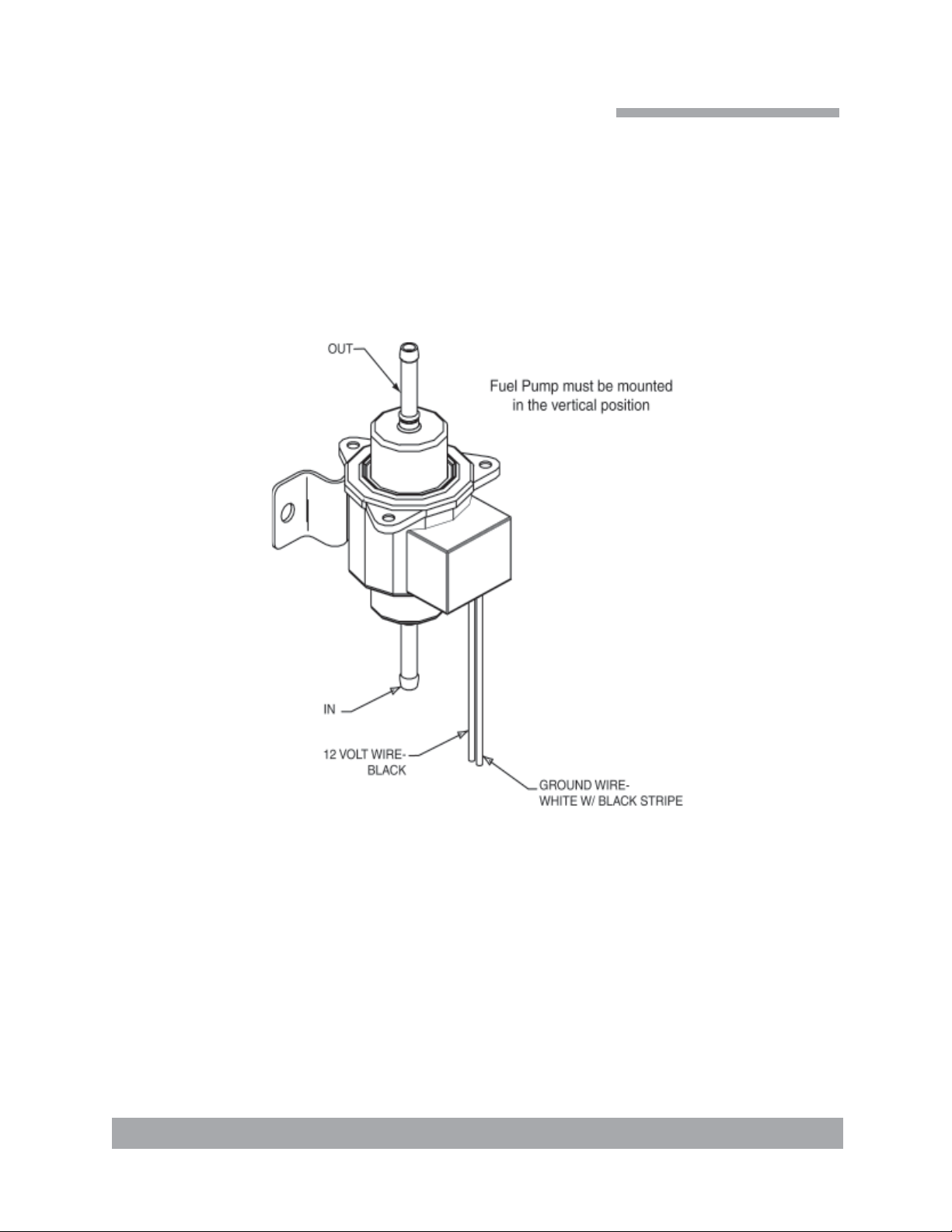
Fuel Pump Assembly
B-4627 Rev -
Boxxer H2O
Quick Refer ence
Boxxer H2O Owner’s Manual
Page 6

Boxxer H2O
This page intentionally left blank.
Boxxer H2O Owner’s Manual
HydraMaster Corporation
Page 7
Boxxer H2O
General Information
The HydraMaster Boxxer H20 is a purpose designed machine to accommodate the needs
of the Water Restoration Contractor who is extracting water and not cleaning carpet. The
basis of the machine is a 27 HP Liquid Cooled V Twin engine that is directly coupled via
the patented BUCS coupling system to a T uthill 4007 Dominator blower. This combination
produces over 400 CFM of air flow, more than enough to extract water with one or two
wands.
In addition to this high performance Power Pack, the Boxxer H20 comes with a 100 gallon
recovery tank. The reliable Dura-Flo Automatic Pump Out is an option which allows you
to extract water without the need to shut down and empty the recovered water.
In addition to the obvious performance aspects of this machine, it was designed to deliver
maximum reliability and to be easily serviced. All the major component s have been proven
in other HydraMaster Truckmounts and this new machine was put together with an eye
towards simple, quick maintenance. All service point s are conveniently located so routine
maintenance takes only a few minutes to perform.
As with any machine, it is important to use the Boxxer H2O correctly. Operating the machine is simple; just start the engine with the vacuum hoses disconnected, let it warm up
for two or three minutes, advance the throttle to the maximum operating position, connect
the vacuum hoses and you are ready to extract water. We strongly suggest that the operator of the machine be well acquainted with the IICRC guidelines for Flood Extraction
and with the various methods of carpet drying that are currently being used. It is also
recommended that the machine operator be familiar with the local municipality’s requirements for the proper disposal of waste water. Typically waste water is to be deposited in
the city sewer system and never in a gutter or storm drain where it would eventually find
it’s way into a stream, river, lake, ocean or public water supply system.
Page 1-1: General Information
Page 8

Boxxer H2O
The manufacturer uses this symbol throughout the manual to
warn of possible injury or death.
This symbol is used to warn of possible equipment damage.
This symbol is used to warn of regulatory or legal issues.
Monday - Friday (425) 775-7276 Parts
8:00 am to 5:00 pm (425) 775-7275 Service
PACIFIC STANDARD TIME (800) 426-4225 Parts / Service FAX
Page 1-2: General Information
Hours Telephone Numbers
HydraMaster Corporation
Page 9

Boxxer H2O
Precautions
ENGINE COOLING: Units employing internal combustion engines must not be enclosed
within a van with doors and windows closed. Excessive temperatures within the engine
will result in premature engine failure and a compromise of applicable warranty.
MOVING PARTS: Never touch any part of the machine that is in motion. Severe bodily
injury may result.
HOT SURF ACES: During the operation of this equipment, many surfaces on the machine
will become very hot. When near the van for any reason care must be taken not to touch
any hot surface, such as blower, engine, exhaust, etc.
HEARING PROTECTION: The Occupational Safety and Health Administration (OSHA)
recommends the use of hearing protection when a technician is exposed to an average of
85 decibels (this is an average of exposure over an 8 hour period). This equipment can
produce 85 decibels to a distance of 10 feet. Please check with your local state agencies
to see if OSHA standards apply to your application.
NO SMOKING: It is unsafe to smoke in or around the vehicle.
CARBON MONOXIDE: This unit generates toxic fumes. Position the vehicle so that the
fumes will be directed away from the job site. Do not park where exhaust fumes can enter
a building through open doors, windows, air conditioning units or kitchen fans.
Page 1-3: General Information
Page 10
Boxxer H2O
TOXIC FUMES: Do not occupy the vehicle when the cleaning equipment is operating.
Toxic fumes may accumulate inside a stationary vehicle.
ENGINE EXHAUST: The engine exhaust from this product contains chemicals known to
the State of California to cause cancer, birth defects or other reproductive harm.
PORTABLE GAS TANK: Never operate this machine with a portable gas can inside the
truck. Doing so increases the risk of a fire or explosion.
TRANSPORTA TION OF FUEL CONTAINERS: Transportation in a vehicle of any vented
fuel container that presently has or has ever contained a flammable liquid is strictly forbidden by HydraMaster Corporation and by federal and state regulation.
THROUGH-FLOOR DRILLING: Be cautious when drilling holes through the van floor.
Many vans have critical components mounted directly below the van floor that could be
damaged by a misplaced drill bit. (See Product Support Bulletins 92102, 94062 and 94063
at the end of the manual.)
LEVEL OPERATION: During operation, van or trailer must be parked on level ground not
to exceed + or - 10 degrees. Failure to insure proper leveling may prevent proper internal
lubrication of engine and vacuum blower.
The machine cannot be run in the IDLE position for carpet or floor extraction. This will void
the warranty.
EXHAUST SYSTEM: Do not allow flammable material (i.e. oil, fuel, plastic or wood products) to come in contact with the exhaust system.
Page 1-4: General Information
HydraMaster Corporation
Page 11

Boxxer H2O
Responsibilities
In Dodge vans the fuel tanks are located directly against the floor . Caution must be used
when drilling any holes through the floor. (See Product Support Bulletin 94062 at the end
of this manual.)
T o purchase heavy duty 24- 60 amp hour battery and have the battery ‘slow’ charge if new .
If the battery is not fully charged, damage can occur to the engine charging regulator.
Reading of owner’s manual: It is the purchaser’s responsibility to read the unit opera-
tion manual and to familiarize himself with the information contained therein.
Special attention should be paid to all Cautions and Warnings.
The Sales Representative’s responsibilities are:
ACCEPTANCE OF SHIPMENT:
1. If the unit shows any outward signs of damage, do not sign the delivery
receipt until you have closely inspected the unit and noted any damage
on the delivery receipt.
2. The salesman from whom you purchased your unit is responsible for
supervising the correct installation of the unit in your vehicle and thoroughly training you in its operation, maintenance and precautions.
CORRECT INSTALLATION INCLUDES:
• Vehicle of proper load carrying capacity (recommendation: 3/4 ton).
• Installation of through-floor fittings for gasoline fuel lines.
Page 1-5: General Information
Page 12

Boxxer H2O
• Placing the unit and recovery tank in your vehicle and securing them
with bolts or tie down cleats.
• Connecting gasoline lines.
• Connecting the battery.
• Checking the vacuum blower and engine oil levels prior to
staring the unit.
• Starting the unit to check the engine and see that all systems
function normally.
• Checking all hoses, wands, etc. for correct operation.
TRAINING:
• A thorough review of the operation manual with purchaser.
Instruction and familiarization in:
• How to correctly start up and shut down the unit.
• How to correctly recover with the unit.
• Where and how often to check and change component oil levels.
• How the unit’s systems work.
• How to troubleshoot the unit.
• How to do basic repairs.
• Safety precautions and their importance.
• A thorough review of the unit warranty and warranty procedures.
.
Page 1-6: General Information
HydraMaster Corporation
Page 13
Boxxer H2O
Vehicle Preparation
When selecting a truck, remember the preferable vehicle for a Boxxer H2O installation is a
cargo van with a heavy-duty suspension package and a 3/4 capacity. A 3/4 ton or larger
capacity van, with a 2,400 pound payload capacity, is required.
TRUCK PREP ARATION
The manufacturer recommends the installation of a spray-on bed liner in the vehicle prior
to installation of machine.
Be cautious when drilling any holes through the van floor. Many vans have
critical components mounted directly below the van floor that could be damaged by a misplaced drill bit. (See Product Support Bulletins 92101, 94062,
and 94063 at the end of this manual.)
This provides ‘metal to cushion’ mounting rather than ‘metal to metal’ and makes for an
attractive van interior . It is highly recommended to install roof vents in vehicles operated in
hot weather locations. Roof vent positions are shown in Figure 1-1.
Figure 1-1 Roof Vents
Page 1-7: General Information
Page 14
Boxxer H2O
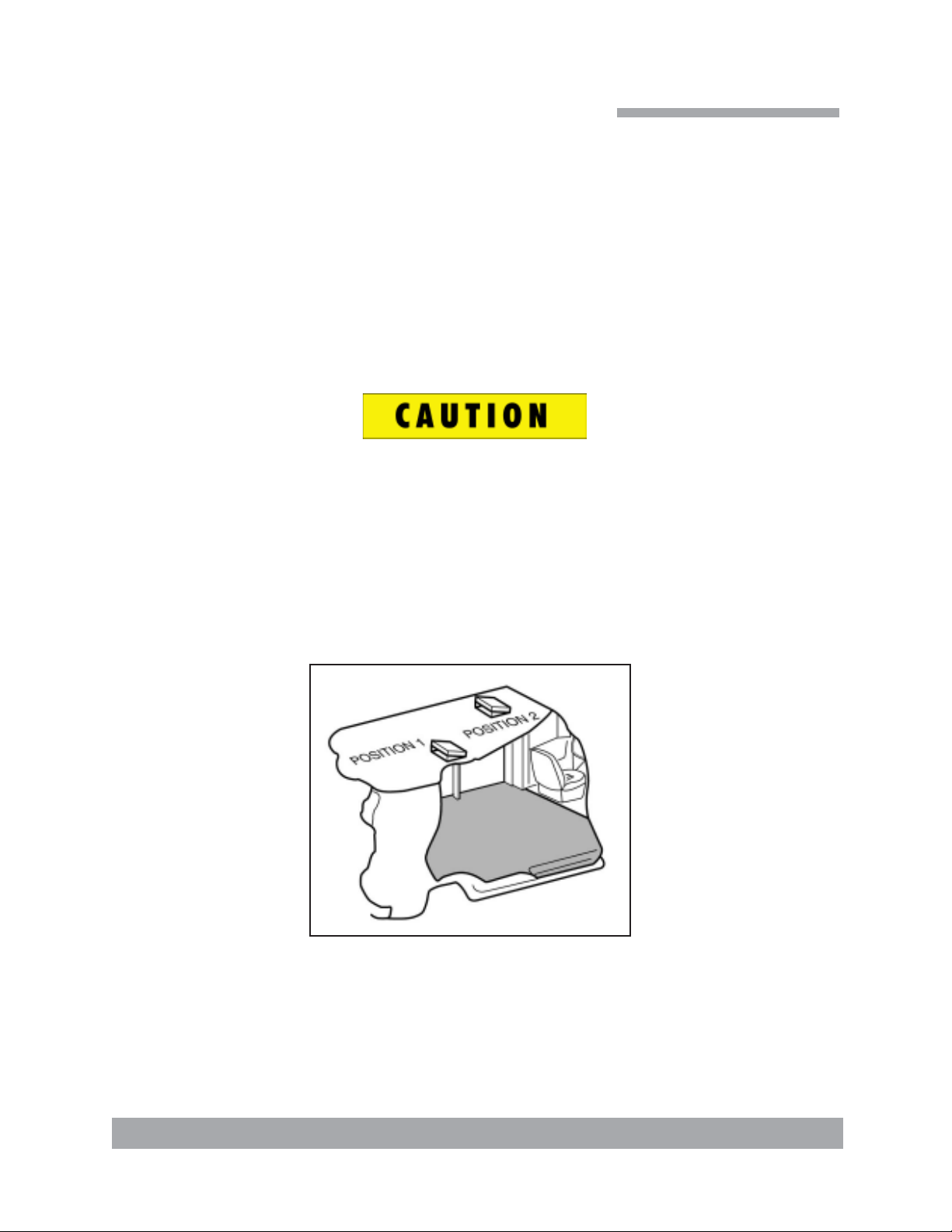
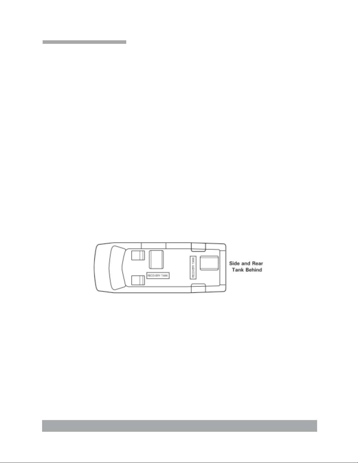
PLACEMENT OF UNIT IN VEHICLE
There are two recommended unit placements (shown in Figure 1-2):
SIDE DOOR:
Most installations are side door. This provides rear access for accessories and hoses as
well as unobstructed access to the component/working side of the machine, thus making
it a bit easier to perform maintenance and/or repair without removing the unit from the
truck.
REAR DOOR:
Although this location partly limits working access, it does direct the noise away from the
cleaning site. Some cleaners in the colder areas prefer this location because it puts the
weight over the rear wheels for better traction in ice and snow. Rear mounting requires the
unit to be slid to the right side as far as possible.
This not only provides adequate working space on the component side of the unit but also
improves weight distribution inside the van (engine and component weight line up over
drive shaft). Also, it is physically easier to load the unit into the rear door due to the height
of the van bed.
Figure 1-2 Recommended Placement
Page 1-8: General Information
HydraMaster Corporation
Page 15
Boxxer H2O
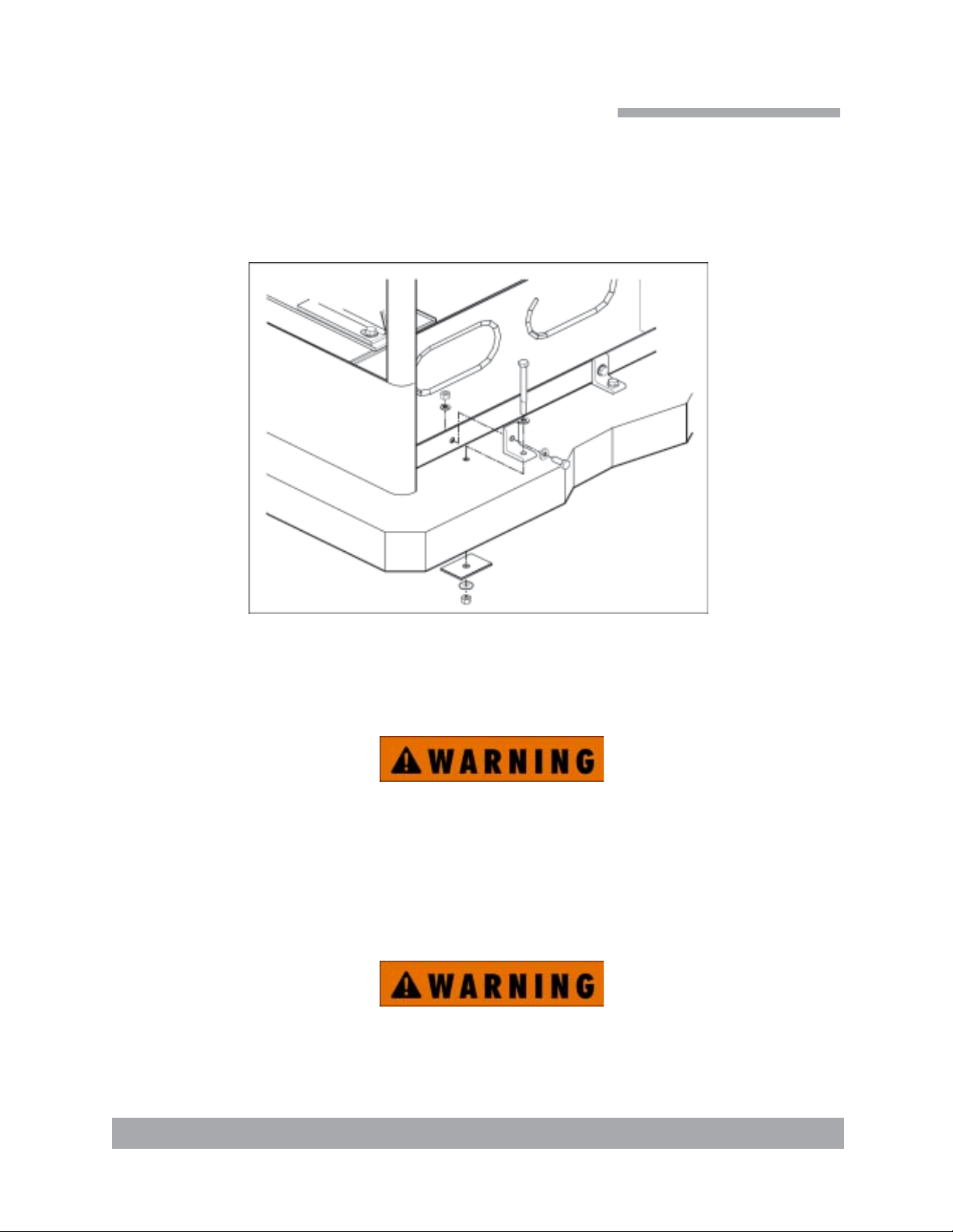
Machine Tie Down Cleats
Secure the machine to the floor of the van with the four tie down cleats provided. This
safety measure will ensure that the machine will not slide inside the van. See the following illustration for the correct installation.
Figure 1-4 Installation Using Tie-down Cleats
Ensure that the machine is well secured to the floor of the van with the hardware
supplied. A sudden stop or crash will cause the machine to rocket forward. Protect
yourself and the machine. SECURE IT!
It is recommended by the manufacturer that the exhaust from the front
of the machine be vented down under the truck to prevent carbon monoxide from entering the job site. Always park the truck so the exhaust is
blowing away from the job site.
The manufacturer also recommends the installation of aluminum vents in
the truck roof to allow heat to escape.
Never operate this machine with a portable gas can inside the truck. Doing
so increases the risk of a fire or explosion.
Mount a fire extinguisher just inside the rear or side door for emergencies.
Page 1-9: General Information
Page 16

Boxxer H2O
Do not use a portable propane tank inside of the truck or van. Doing so may
increase risk of fire or explosion.
Transportation in a vehicle of any vented fuel cont ainer that presently holds
or has ever held a flammable liquid is strictly forbidden by HydraMaster Corporation and by federal and state regulation.
The engine exhaust from this product contains chemicals known to the St ate
of California to cause cancer, birth defects or other reproductive harm.
Page 1-10: General Information
HydraMaster Corporation
Page 17

Boxxer H2O
High Altitude Operation
Preparation
Although this unit has been factory adjusted, it may require additional adjustments
to achieve optimum performance, for instance higher altitudes may require carburetor
adjustment. When required, consult an authorized representative. Elevation plays a key
role in how the machine will operate.
The factory setting of the machine is set for elevations from 0—3,000 feet. Any time the
machine is operated above 3,000 feet there are two areas on the machine the may need
adjustment.
The first area is the carburetor jet. The higher the elevation, the less air is provided to the
fuel mixture. This will make the engine run ‘rich’, and, in turn will result in the loss of
power , excessive heat in the exhaust, and carbon buildup in the exhaust system. The jet
sizes vary per engine and elevation. Consult HydraMaster to obtain proper jet size.
Page 1-11: General Information
Page 18

Boxxer H2O
Local Water Precautions
WASTE WATER DISPOSAL ADVISORY
There are laws in most communities prohibiting the dumping of recovered “gray” water
from carpet cleaning in any place but a sanitary treatment system.
The extracted water recovered into your unit’s vacuum tank must be processed before
being safe for streams, rivers and reservoirs.
IN ACCORDANCE WITH THE EPA, ST A TE AND LOCAL LA WS, DO NOT DISPOSE OF
WASTE WATER INTO GUTTERS, STORM DRAINS, STREAMS, RESERVOIRS, ETC.
In most cases, an acceptable method of waste water disposal is to discharge into a municipal sewage treatment system after first filtering out solid material such as carpet fiber.
Access to the sanitary system can be obtained through a toilet, laundry drain, RV dump,
etc. Permission should first be obtained from any concerned party or agency.
One disposal method which usually complies with the law is to accumulate the waste
water and haul it to an appropriate dump site. Another solution to the disposal problem is
to equip your machine with an Automatic Pump-Out System. These systems are designed to remove waste water from the extractor’s recovery system and actively pump the
water through hoses to a suitable disposal drain. Properly designed, they will continuously monitor the level of waste water and pump it out simultaneously to the cleaning
operation. The hidden benefit of this process is that the technician does not have to stop
his cleaning to empty the recovery tank.
HydraMaster produces an A.P.O. System available which can be ordered with new equipment or installed later.
The penalties for noncompliance can be serious. Always check local laws and regulations
to be sure you are in compliance.
Page 1-12: General Information
HydraMaster Corporation
Page 19

Machine Specifications
Frame: Welded Steel
Weight: 572 lbs.
Engine: Vanguard 27HP Briggs and Stratton
Pressurized Oil System
Spin-on Filter and Oil Cooler
Ignition: Electronic, Keystart
Vacuum Blower: Dominator 4007, Tuthill/M-D Tri-Lobe,
Instruments: Hour Meter, Machine Runtime
Keyed Ignition, Start/Stop
Vacuum Gauge
APO Switch
Recovery Tank “Full” Light
Boxxer H2O
Recovery T ank: 100 Gallon Aluminum, Epoxy Finish
Cleaning Wand: Stainless Steel
Replaceable Grip
Vacuum Hose: 2" Reinforced, 1-1/2" Reinforced.
Standard Equipment: Machine Power Console
Full Instrumentation
Vacuum Recovery Tank
100 ft, 2" Vacuum Hose
10 ft, 1-1/2" Wand Whip Line
Battery Box
Van Decal Package
Van Installation Kit
Operation Manual
HydraMaster Jacket
Page 2-1: Machine Specifications
Page 20
Boxxer H2O
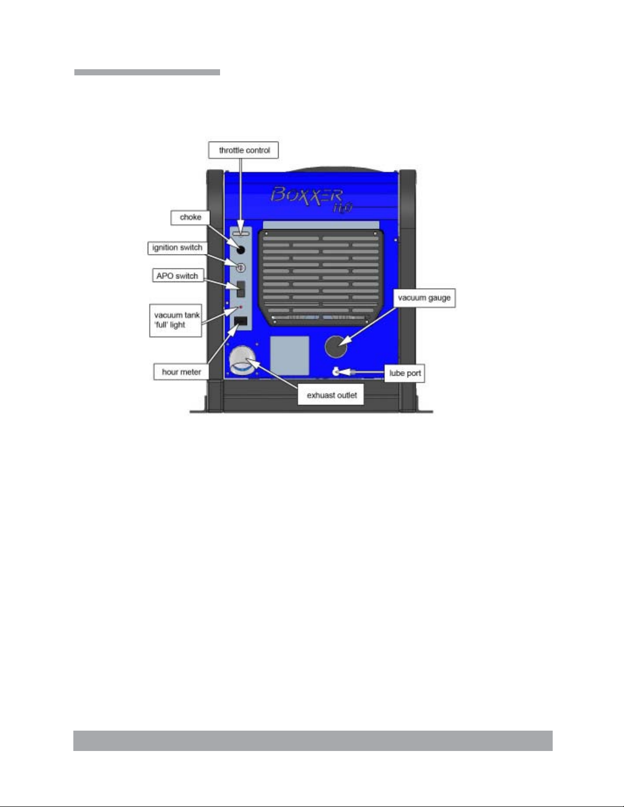
Machine Layout
Throttle Control - Controls the speed of the engine.
Choke - Pull style cable for cold starts.
Ignition Switch - Main power control to the machine.
APO Switch - Activates/Deactivates Automatic Pump Out.
Vacuum Tank ‘Full’ Light - Lights up when vacuum tank is full.
Hour Meter - Displays total number of hours machine has been run during its lifetime.
Exhaust Outlet - Engine and blower exhaust outlet.
Lube Port - Allows blower to be lubricated.
Vacuum Gauge - Displays engine temperature and vacuum.
Page 2-2: Machine Specifications
HydraMaster Corporation
Page 21

Perform daily and periodic maintenance as specified in this Owner’s Manual.
The machine cannot be run in the “IDLE” position for water recovery. This
will void the warranty.
Never run the machine on any speed other than full throttle during water
extraction. Extracting at any other speed will void the warranty.
Start Up
Boxxer H2O
Operating Instructions
Flood Extraction
1. Start the engine with the THROTTLE cable to the “IDLE” position.
Allow the machine to run in idle for 2 - 3 minutes to warm up.
2. Connect required length of hoses.
3. Connect wand or tool.
4. Pull the THROTTLE cable to the “HIGH” position.
5. If used, turn PUMP OUT switch to “ON” .
6. Commence water extraction.
Shut Down
1. Remove the vacuum hose.
2. At this time, the blower should be lubricated with an oil-based lubricant. See
the blower manufacturer’s manual or the maintenance section for lubrication
information.
3. Lower the engine RPMs to idle.
4. Turn the key off.
5. Drain the vacuum tank. The vacuum filter should be cleaned prior to mobilization of the van.
In accordance with the EPA, state and local laws, do not dispose of waste water
into gutters, storm drains, streams, reservoirs, etc.
6. Perform daily maintenance as prescribed in this manual.
Page 3-1: Operating Instructions
Page 22

Boxxer H2O
This page intentionally left blank
Page 3-2: Operating Instructions
HydraMaster Corporation
Page 23

Boxxer H2O
Machine Maintenance
To avoid costly repairs and downtime, it is imperative to develop and practice
good maintenance procedures from the beginning. These procedures fall into daily , weekly ,
monthly and quarterly increments, and are outlined below. All recommended maintenance must be performed by competent service personnel.
Important: Record the date and machine hours on the maintenance log.
We have provided a maintenance log for your convenience at the end of this section.
Records of maintenance must be kept and copies may be required to be furnished to
HydraMaster before the warranty is honored. It is recommended that you affix a copy of
the log on the vehicle door near your unit for convenience and to serve as a maintenance
reminder.
OPERATIONAL MAINTENANCE
DAILY:
• Check engine oil level.
• Visually inspect machine for loose wires, oil leaks, etc.
• Lubricate blower with an oil based lubricant through blower inlet.
WEEKLY:
• Inspect vacuum tank s/s filter and filter basket for tears, holes, etc.
Clean, repair or replace as needed.
• One time change of oil and oil filter after first 50 hours of use.
• Check oil level in blower.
• Check drive system screws. Tighten as needed.
• Check all nuts and bolts. Tighten as needed.
• Inspect vacuum relief valve. Clean and lubricate as necessary.
• Clean vacuum tank thoroughly with high pressure washer.
• Check wiring for chafing.
• Change engine oil (every 100 hrs.).
Page 4-1: Machine Maintenance
Page 24

Boxxer H2O
MONTHLY:
• Change oil filter (every other oil change).
It is important to use only Briggs oil filters. Even though an
aftermarket filter may fit, the internal by-pass system may not be
compatible with the Briggs engine resulting in low oil pressure.
• Check engine air cleaner filter. Clean as necessary.
• Check water level in battery. Clean connections as needed.
QUARTERLY:
• Check fuel lines.
• Clean and gap spark plugs.
• Check drive coupler for cracks or wear. Replace as necessary.
• Change oil in blower.
500 HOURS:
• Check coupler element between the engine and the blower, replace as necessary.
OVERALL MACHINE MAINTENANCE
Maintaining the original appearance of your unit is import ant for two reasons:
1. It represents a big dollar investment for your recovery business and its appearance
should reflect that fact. A dirty machine is not professional.
2. Maintenance, troubleshooting, and repair is much easier to accomplish on a clean,
well maintained unit. Regular cleaning of the machine offers you an opportunity to
visually inspect all facets of the machine and spot potential problems before they
occur.
Page 4-2: Machine Maintenance
HydraMaster Corporation
Page 25

Boxxer H2O
The following maintenance is recommended by the manufacturer at the frequency indicated.
AFTER EACH JOB
• Check recovery tank, s/s filter and filter basket as required.
DAILY
• Wipe machine down thoroughly with a damp cloth.
• Flush recovery tank out thoroughly.
• Empty filter basket and inspect for rips, tears, etc. Replace as needed.
• Remove, thoroughly clean and reinstall stainless steel filter screen in
recovery tank.
• Inspect and clean vacuum slot on recovery wand.
• Check wand head for sharp edges that could tear carpet. File down
as needed.
• Clean wand to maintain original appearance.
• Wipe down vacuum hoses as needed.
• Visually inspect hoses for cuts, etc.
WEEKLY
• Wipe down entire unit as needed.
• Apply good coat of auto wax to all painted surfaces inside and out, and
to control panel.
• Thoroughly clean recovery tank using high pressure water.
• Remove stainless steel filter in recovery tank and thoroughly clean, removing
all lint buildup. Inspect for damage and reinstall.
• Remove filter basket. Thoroughly clean and reinstall.
• Apply light coat of auto wax to wand.
• Thoroughly clean vacuum hoses including hose cuffs.
• Inspect for wear or damage to hoses and quick connect fittings.
Page 4-3: Machine Maintenance
Page 26

Boxxer H2O
This page intentionally left blank
Page 4-4: Machine Maintenance
HydraMaster Corporation
Page 27

BOXXER H2O MAINTENANCE LOG
MAX
HRS
8
8
8
8
See Note
25
25
25
25
25
25
DAILY SERVICE
ENGINE OIL - check
MACHINE - general inspection
VACUUM TANK FILTER BAG - clean
BLOWER INLET - spray with lubricant
WEEKLY SERVICE
OIL - change with filter
BLOWER - check oil level
DRIVE SYSTEM - tighten screws
NUTS & BOLTS - check tightness
VAC. RELIEF VALVE - inspect, clean, lube
VACUUM TANK - clean
WIRING - check for chafing
BLOWER
ENGINE
OIL RECOMMENDATIONS
40 weight non-detergent
See Briggs engine manual
DATE & HOURS
Note: Break-in period determined by manufacturer. Refer to engine manual.
100
100
100
300
300
300
400
MONTHLY SERVICE
ENGINE OIL & FILTER - change
ENGINE AIR CLEANER - clean
BATTERY WATER LEVELS - check
QUARTERLY SERVICE
(3 MONTHS)
FUEL LINES - check
SPARK PLUGS - clean and gap
DRIVE COUPLER - check for wear
BLOWER OIL - change
Page 28

Page 29

Machine Assemblies
and Parts Lists
Figure 5-1 Machine Assembly - Front V iew - Lef t Side
D-6800 Rev -
Boxxer H2O
2
3
1
Page 5-1: Machine Assemblies and Parts List
Page 30

Boxxer H2O
Figure 5-2 Machine Assembly - Front View - Right Side
D-6800 Rev -
Machine Assembly Parts List
Item Part Number Description Qty
1 610-001-036 Assembly, Frame - Boxxer H2O (Fig. 5-3 & 5-5) 1
2 610-050-033 Assembly, Machine Left Side Cover (Fig. 5-9) 1
3 610-050-033 Assembly, Machine Right Side Cover (Fig. 5-10) 1
Page 5-2: Machine Assemblies and Parts List
HydraMaster Corporation
Page 31

Figure 5-3 Frame Assembly - Front View - Lef t Side
D-6801 Rev -
21
Boxxer H2O
10
3
19
20
5
2
6
1
11
12
10
16
4
16
Page 5-3: Machine Assemblies and Parts List
Page 32

Boxxer H2O
Figure 5-4 Frame Assembly - Front View - Right Side
D-6801 Rev -
21
6
11
12
8
13
14
15
10
17
18
8
13
14
HIDDEN
HIDDEN
14
15
9
10
7
9
HIDDEN
HIDDEN
HIDDEN
HIDDEN
15
6
8
13
HIDDEN
HIDDEN
HIDDEN
HIDDEN
Page 5-4: Machine Assemblies and Parts List
HydraMaster Corporation
Page 33

Boxxer H2O
Frame Assembly Parts List
Item Part Number Description Qty
1 000-055-186 Frame, Weldment - Boxxer H2O 1
2 610-003-036 Assembly, Engine - Boxxer H2O (Fig. 5-5) 1
3 610-002-036 Assembly, Blower - Boxxer H2O (Fig. 5-6) 1
4 610-020-036 Assembly, Dash Boxxer H2O (Fig. 5-7) 1
5 601-003-036 Assembly, Exhaust - Boxxer H2O (Fig. 5-8) 1
6 000-092-017 Mount, Rubber Isolator - Boxxer H2O 3
7 000-105-012 Plate, Machine Serial I.D. 1
8 000-033-053 Clamp, 1-1/2" Cushion Loop 3
9 000-140-015 Rivet, 1/8" x 1/4" Lg. Pop 2
10 000-020-063 Bushing, Snap, 0.55" O.D. x 0.312" I.D. 4
11 000-143-013 Screw, 5/16"-18UNC x 1.00" Lg. Grade 8 12
12 000-174-018 Washer, 5/16" Lock 12
13 000-174-001 Washer , #10 Flat 3
14 000-174-014 Washer, #10 Lock 3
15 000-143-126 Screw, #10-24UNC x 0.50" Lg. Hex Head 3
16 000-027-033 Cap, Frame End - Raw 2
17 000-068-660 Hose, 1/4" I.D. Trident Fuel - Bulk 1
18 000-131-055 Insulation, Hi T emp Sleeving - Bulk 1
19 000-068-030 Hose, 5/32" I.D. Vacuum - Bulk 1
20 000-068-030 Hose, 5/32" I.D. Vacuum - Bulk 1
21 000-081-036 Label, ANSI Warning Text Only 2
Page 5-5: Machine Assemblies and Parts List
Page 34

Boxxer H2O
Figure 5-5 Engine Assembly
D-6802 Rev A
26
15
6
5
4
21
25
19
20
2
16
1
18
19
11
12
14
23
8
7
1322
Page 5-6: Machine Assemblies and Parts List
17
24
7
10
9
10
7
3
10
11
8
HydraMaster Corporation
Page 35

Boxxer H2O
Engine Assembly Parts List
Item Part Number Description Qty
1 000-047-026 Engine, Briggs & Stratton 27HP 1
2 000-047-026 Air Cleaner - Daihatsu Engine 1
3 000-092-011 Mount, Engine 27 B&S 1
4 000-057-050 Gasket, Thermostat Housing Daihatsu Engine 1
5 000-047-026 Thermostat, Stock B&S 27HP 1
6 000-047-026 Thermostat Housing, B&S 27 HP Stock 1
7 000-174-007 Washer, 1/2" Flat 4
8 000-094-037 Nut, 1/2"-13UNC Hex 2-Way Locking - z/p 2
9 000-143-568 Screw, 5/16"-18UNC x 2.50" Lg. Hex Head Grade 8 4
10 000-174-004 Washer , 5/16" Flat 8
11 000-094-081 Nut, 5/16"-18UNC Hex 2-Way Locking 5
12 000-033-117 Clamp, 1" Cushion Loop w/ 7/16" Mount Hole 1
13 000-052-063 Bushing, 14mm x 1/4" NPT Engine Oil Drain Adapter 1
14 000-068-221 Hose, Engine Oil Drain 1
15 000-068-595 Hose, 1.75" x 18.25" x 90 Molded Radiator 1
16 - - - Screw, 8mm x 25mm Lg. Hex Head W asher 2
17 000-049-014 Filter, 16HP Oil - All B & S 1
18 000-1 11-171 Pump, B&S 27 HP W ater 1
19 000-056-006 Fuse Holder, Inline Weather Proof 2
20 000-056-011 Fuse, 30 AMP Plug In 1
21 000-113-007 Radiator, 27 HP B & S Engine 1
22 000-052-082 Elbow, 1/4" NPT Street x 45° 2
23 000-143-155 Screw, 1/2"-13UNC x 3.50" Lg. Hex Head 2
24 000-077-010 Key, 1/4" x 1-1/2" Lg. Class 2 Fit 1
25 000-056-005 Fuse, 25 AMP Plug In 1
26 000-049-063 Filter, Replacement - Engine Air Daihat su 1
Page 5-7: Machine Assemblies and Parts List
Page 36

Boxxer H2O
Figure 5-6 Blower Assembly
D-6803 Rev A
13
6
5
23
8
18
20
21
20
16
15
30
14
1
23
8 13
10
3
8
8
13
29
2
5
12
7
22
26
25
19
Page 5-8: Machine Assemblies and Parts List
27
28
4
9
8
11
29
12
7
17
23
8
24
HydraMaster Corporation
Page 37

Boxxer H2O
Blower Assembly Parts List
Item Part Number Description Qty
1 000-1 1 1-167 Blower , MD 4007 C-Face Dual Shaft 1
2 000-015-814 Bracket, Dominator Mounting 1
3 000-042-063 Housing, Bell - Modified 1
4 000-039-053 Coupler, 50 Series 1
5 000-174-007 Washer, 1/2" Flat 2
6 000-094-037 Nut, 1/2"-13UNC Hex 2-Way Locking - Z/P 1
7 000-052-142 Elbow, 3/8" FPT x FPT 2
8 000-174-021 Washer, 3/8" Lock 19
9 000-143-025 Screw, 3/8"-16UNC x 1.25" Lg. Hex Head Grd 8 4
10 000-143-200 Screw, 3/8"-16UNC x 1.50" Lg. Grade 8 4
11 000-174-004 Washer , 5/16" Flat 4
12 000-052-077 Nipple, 3/8" NPT Close 2
13 000-143-018 Screw, 3/8"-16UNC x 1.00" Lg. Grade 8 7
14 000-001-115 Adapter, Blower Flange T o 3" M Slip 1
15 000-174-019 Washer, 1/4" Lock 6
16 000-143-001 Screw, 1/4"-20UNC x 0.75" Lg. Hex Head 6
17 000-013-069 Box, Blower Collector - Weldment 1
18 000-093-104 Silencer, Weldment 1
19 000-052-106 Insert, 1/8" NPT x 5/32" Barb x 90° 2
20 000-033-013 Clamp, Size #48 Hose 2
21 000-068-398 Hose, 3" I.D. x 3 Ply Silicone 1
22 000-143-155 Screw, 1/2"-13UNC x 3.50" Lg. Hex Head 1
23 000-174-005 Washer, 3/8" Flat 8
24 000-143-139 Screw, 3/8"-16UNC x 4.00 Lg. Grd 8 4
25 000-068-219 Hose, Drain 1
26 000-068-219 Hose, Drain 1
27 000-078-424 Kit, Metal Ring Retainer 3 Pc. (Replacement) 1
28 000-152-010 Sleeve, 50 Series S plit (Replacement) 1
29 000-027-112 Plug, Oil Sight Glass Tuthill Blower 2
30 000-174-003 Washer, 1/4" Flat 6
Page 5-9: Machine Assemblies and Parts List
Page 38

Boxxer H2O
Figure 5-7 Dash Assembly
D-6804 Rev A
13
12
11
1
14
2
11
19
18
6
5
3
7
23
22
4
12
13
21
12
11
23
22
11
12
21
10
17
Page 5-10: Machine Assemblies and Parts List
16
15
20
9
8
HydraMaster Corporation
Page 39

Boxxer H2O
Dash Assembly Parts List
Item Part Number Description Qty
1 000-100-163 Panel, Dash 1
2 000-100-145 Panel, Grill 1
3 000-157-008 Switch, Ignition 1
4 000-074-018 Meter, Rectangular w/o Bezel 1
5 000-025-002 Cable, Choke (3 Foot) 1
6 000-025-030 Cable, Throttle 1
7 000-157-040 Switch, 20 AMP Rocker 1
8 000-074-017 Gauge, 0-30” Hg Vac. 2 1/2” HydraMaster Face 1
9 000-052-272 Cup, Gravity Feed Oil Blower Lubrication Port 1
10 000-084-011 Light, Red Led Indicator Mini 1
11 000-174-001 Washer, #10 Flat 13
12 000-174-014 Washer, #10 Lock 13
13 000-143-126 Screw, #10-24UNC x 0.50” Lg. Hex Head 9
14 000-131-131 Trimlock, 3/8” x 1/8” Groove - Bulk 1
15 000-174-032 Washer, 3/8” Flat 2
16 000-052-096 Insert, #F23 (1/8” FPT x 3/16” Barb) 1
17 000-081-036 Label, ANSI Warning 1
18 000-081-036 Label, Dash Controls 1
19 000-081-036 Label, Water Recovery System 1
20 000-081-036 Label, Lube Port - Boxxer H2O 1
21 000-143-133 Screw, #10-24UNC x 1.50” Lg. Hex Head 4
22 000-033-057 Clamp, 1” Cushion Loop 2
23 000-094-034 Nut, #10-24UNC Nylock 2
Page 5-11: Machine Assemblies and Parts List
Page 40

Boxxer H2O
Figure 5-8 Exhaust Assembly
D-6805 Rev -
2
13
18
16
17
5
13
14
11
1
9
8
7
10
171615
3 13
11
12
6
12
413
11
Page 5-12: Machine Assemblies and Parts List
HydraMaster Corporation
Page 41

Boxxer H2O
Exhaust Assembly Parts List
Item Part Number Description Qty
1 000-125-223 Tube, Lower Exhaust - Boxxer H2O 1
2 000-093-103 Muffler , Weldment - Boxxer H2O 1
3 000-015-931 Bracket, Exhaust Support - Boxxer H2O 1
4 000-001-098 Adapter, Exhaust Turndown - W eldment 1
5 000-068-398 Hose, 3" I.D. x 3 Ply Silicone - Bulk 1
6 000-068-398 Hose, 3" I.D. x 3 Ply Silicone - Bulk 1
7 000-057-177 Gasket, Exhaust Donut 1.50" 1
8 000-125-128 Tube, 1-3/8" O.D. x 1/8" Wall x 7/8" Long 1
9 000-143-124 Screw, 5/16"-18UNC x 1.75" Lg. Hex Head 2
10 000-094-081 Nut, 5/16"-18UNC Hex 2-Way Locking 2
11 000-174-003 Washer , 1/4" Flat 8
12 000-094-009 Nut, 1/4"-20UNC Hex Nylock 6
13 000-033-013 Clamp, Size #48 Hose 4
14 000-143-001 Screw, 1/4"-20UNC x 0.75" Lg. Hex Head 2
15 000-143-013 Screw, 5/16"-18UNC x 1.00" Lg. Grade 8 2
16 000-174-018 Washer, 5/16" Lock 4
17 000-174-004 Washer , 5/16" Flat 4
18 000-143-187 Screw, 8mm x 25mm Lg. Grade. 10.9 Hex Head 2
Page 5-13: Machine Assemblies and Parts List
Page 42

Boxxer H2O
Figure 5-9 Machine Left Side Cover Assembly
D-5587 Rev -
5
6
1
6
5
4
3
2
4
3
Machine Left Side Cover Assembly Parts List
Item Part Number Description Qty
1 000-041-417 Cover, Left Side Machine - Boxxer 427 1
2 000-105-313 Plate, Hydramaster Name- Roto T ank 1
3 000-174-001 Washer, #10 Flat 2
4 000-143-166 Screw, #10-24UNC x 0.38" Lg. Hex Head 2
5 000-094-034 Nut, #10-24UNC Nylock 2
6 000-089-003 Magnet, Treadmaster 2
Page 5-14: Machine Assemblies and Parts List
HydraMaster Corporation
Page 43

Figure 5-10 Machine Right Side Cover Assembly
D-5762 Rev -
1
6
5
Boxxer H2O
6
5
4
2
3
4
3
Machine Right Side Cover Assembly Part s List
Item Part Number Description Qty
1 000-041-419 Cover, Right Side Machine - Boxxer 427 1
2 000-105-313 Plate, Hydramaster Name- Roto T ank 1
3 000-174-001 Washer , #10 Flat 2
4 000-143-166 Screw, #10-24UNC x 0.38" Lg. Hex Head 2
5 000-094-034 Nut, #10-24UNC Nylock 2
6 000-089-003 Magnet, Treadmaster 2
Page 5-15: Machine Assemblies and Parts List
Page 44

Boxxer H2O
Figure 5-1 1 100 Gallon Universal Recovery Tank Assembly
D-7149 Rev A
12
11
HIDDEN
HIDDEN
HIDDEN
2
26
19
20
9
7
27
20
30
20
29
5
33
37
20
29
6
27
15
HIDDEN
18
HIDDEN
28
13
16
17
8
14
36
35
29
31
4
38
25
10
32
HIDDEN
28
HIDDEN
13
3
HIDDEN
32
28
HIDDEN
21
24 23 22
34
10
13
3
1
Page 5-16: Machine Assemblies and Parts List
HydraMaster Corporation
Page 45

Boxxer H2O
100 Gallon Universal Recovery T ank Assembly Parts List
Item Part Number Description Qty
1 000-159-129 Tank, 100 Gallon Universal Recovery - Weldment 1
2 Fig. 5-12 Assembly, Recovery Tank Cover - 100 Gallon 1
3 000-157-090 Float, Lever Switch 2
4 000-079-091 Kit, Dura-Flow APO - Production (Fig. 5-14) 1
5 Fig. 5-13 Assembly, V acuum Relief V alve 1
6 000-049-152 Filter, Recovery Tank Basket 1
7 000-049-153 Filter, Flat - Recovery Tank 1
8 000-012-002 Block, 6 Post T erminal 1
9 000-015-932 Bracket, Flat Filter Securing - Universal Recovery T ank 1
10 000-033-023 Clamp, 3/4" Nylon Hose 2
11 000-049-154 Deflector, Air - Univeral Recovery Tank 1
12 000-140-023 Rivet, AB8-6A Aluminum Pop 6
13 000-143-126 Screw, #10-24UNC x 0.50" Lg. Hex Head 5
14 000-143-051 Screw, #8-32UNC x 0.75" Lg. Binder Head Phillips 2
15 000-094-059 Nut, #8-32UNF Nylock 2
16 000-086-008 Latch, Bungie 1
17 000-143-539 Screw, #6-32UNC x 0.50" Lg. Button Head Allen 2
18 000-094-063 Nut, #6-32UNC Nylock 2
19 000-174-019 Washer, 1/4" Lock 2
20 000-174-003 Washer, 1/4" Flat 18
21 000-106-019 Plug, 1-1/2" NPT 1
22 000-052-763 Nipple, 1-1/2" IPS Close s/s 1
23 000-169-022 Valve, 1-1/2" Full Port Ball 1
24 000-052-226 Insert,1-1/2" NPT x 1-1/2" Barb (Grey) 1
25 000-081-036 Label, Maintenace And Lubrication Schedule 1
26 000-143-333 Screw, 1/4"-20UNC x 0.50" Lg. Hex Head 2
27 000-174-029 Washer, 3/8" Rubber Back 2
28 000-174-036 Washer, #10 Flat Rubber Backed 5
29 000-143-002 Screw, 1/4"-20UNC x 1.00" Lg. Hex Head 12
30 000-094-009 Nut, 1/4"-20UNC Hex Nylock 8
Page 5-17: Machine Assemblies and Parts List
Page 46

Boxxer H2O
100 Gallon Universal Recovery T ank Assembly Parts List
Item Part Number Description Qty
31 000-166-002 Tray, Soap Jug - Weldment 1
32 000-094-034 Nut, #10-24UNC Nylock 2
33 000-057-206 Gasket, Adapter - Universal Recovery T ank 2
34 000-106-049 Plug, 1" NPT Allen Head 1
35 000-174-060 Washer, 1/4" Flat Rubber Backed 4
36 000-094-113 Nut, 1/4"-20UNC Neoprene Wellnut 4
37 000-001-135 Adapter, Tank T o Ø3.0" x 90° Blower Hose - Universal Recov 1
38 000-106-007 Plug, 1/4" NPT Allen Head 1
Page 5-18: Machine Assemblies and Parts List
HydraMaster Corporation
Page 47

Boxxer H2O
Figure 5-12 100 Gallon Universal Recovery Tank Cover Assembly
D-6919 Rev -
8
2
5
6
7
9
1
3
4
10
11
9
100 Gallon Universal Recovery Tank Cover Assembly Parts List
Item Part Number Description Qty
1 000-041-447 Cover, 100 Gallon Universal Recovery Tank - Weldment 1
2 000-078-039 Vacuum Inlet Stopper Assembly - Recovery Tank 1
3 000-057-015 Gasket, 1-1/2" Bulkhead Fitting 2
4 000-052-219 Adapter, 2" NPT x 2" F Slip 2
5 000-143-539 Screw, #6-32UNC x 0.50" Lg. Button Head Allen 2
6 000-086-008 Latch, Bungie - Strike 1
7 000-094-063 Nut, #6-32UNC Nylock 2
8 000-052-222 Elbow, 2" Barb x 2" FPT 2
9 000-057-202 Gasket, End - Recovery Tank 2
10 000-057-203 Gasket, Middle - Recovery Tank 3
11 000-057-205 Gasket, Side - Recovery Tank - 100 Gallon 2
Page 5-19: Machine Assemblies and Parts List
Page 48

Boxxer H2O
Figure 5-13 Vacuum Relief Valve Assembly
C-6894 Rev -
7
5
3
1
4
8 2
6
V acuum Relief Valve Assembly Part s List
Item Part Number Description Qty
1 000-015-182 Bracket, Vacuum Relief V alve 1
2 000-027-032 Cap, V acuum Releif V alve 1
3 000-125-111 Pipe, V acuum Relief S pring Guide 1
4 000-105-332 Plate, Vacuum Relief V alve Mounting - Universal Recovery T 1
5 000-155-026 Spring, V acuum Relief 1
6 000-143-198 Screw, 3/8"-16UNC x 4" Lg. Hex Head Full Thread 1
7 000-094-077 Nut, 3/8"-16UNC x 1.00" O.D. Knurled 2
8 000-094-101 Nut, 3/8"-16UNC Hex Jam 1
Page 5-20: Machine Assemblies and Parts List
HydraMaster Corporation
Page 49

Figure 5-14 Dura-Flow APO Assembly
D-5654 Rev E
Boxxer H2O
2
38
5
6
7
7
6
13
4
8
6
12
14
4
16
17
15
22
1
5
16
17
9
18
10
19
21
20
Page 5-21: Machine Assemblies and Parts List
Page 50

Boxxer H2O
Dura-Flow APO Assembly Parts List
Item Part Number Description Qty
1 000-1 1 1-169 Assembly , APO Pump - Jabsco 1
2 000-091-042 Motor, Bison 438 Series 1
3 000-015-891 Bracket, APO Clamp 1
4 000-015-890 Bracket, T ank Mounted APO Support 1
5 000-143-566 Screw, 1/4-28UNF x 0.75" Lg. Socket Head 4
6 000-143-074 Screw, 1/4"-20UNC x 0.50" Lg. Hex Head Self-T apping 4
7 000-174-002 Washer, 1/4" Flat 4
8 000-061-131 Knob, Handle - Rdm 2
9 000-052-723 Fitting, 1" NPT Cam Lock - Banjo 100F 1
10 000-052-724 Fitting, 1" NPT Cam Lock - Banjo 100B 1
11 000-157-022 Switch, Relay 1
12 000-012-011 Block, 6 Post 1
13 000-094-027 Nut, #10-24UNC Hex 1
14 000-143-532 Screw,#6-32UNC x 5/8" Lg. Socket Head 2
15 000-068-069 Hose, 3/4" I.D. Weatherhead - Blue - Bulk. 1
16 000-033-026 Clamp, Size #10 Hose 2
17 000-052-338 Insert, #1212 (3/4" NPT x 3/4" Barb) 2
18 000-169-009 Valve, 3/4" FPT Swing Check 1
19 000-052-281 Nipple, 3/4" NPT x 3/4" Male Garden Hose 1
20 000-057-055 Gasket, Garden Hose 1
21 000-027-014 Cap, Garden Hose 1
22 000-052-425 Bushing, 1" NPT x 3/4" FPT 1
Page 5-22: Machine Assemblies and Parts List
HydraMaster Corporation
Page 51

(To be Added)
Boxxer H2O
Page 5-23: Machine Assemblies and Parts List
Page 52

Boxxer H2O
(To be Added)
Page 5-24: Machine Assemblies and Parts List
HydraMaster Corporation
Page 53

Boxxer H2O
This page intentionally left blank
Page 5-25: Machine Assemblies and Parts List
Page 54

Boxxer H2O
Vacuum System
The vacuum pump in this machine is commonly referred to as a ‘positive displacement lobe’
type blower. The performance and life of this unit is greatly dependent on the care and proper
maintenance it receives.
Because of the close tolerances between the lobes and housing of the vacuum blower, solid
objects entering the inlet will damage the internal lobes, gears, bearings or drive system.
T o prevent this, a stainless steel filter screen has been placed at the vacuum inlet inside the
vacuum recovery tank. This stainless steel screen is ‘finger’ tight and should be removed
for cleaning weekly .
T o protect the vacuum blower from overloading and damaging itself, there is a vacuum relief
system installed on the vacuum tank. When the vacuum tank inlet is completely sealed off, a
maximum of 12 HG will be attained.
At the end of each day , an oil based lubricant should be sprayed into the blower lubrication
port before shutting down the machine. Lubricate the vacuum blower daily to prevent rust
deposits and moisture that will decrease the life of the vacuum blower .
Foam passing through the blower could lead to serious problems.
It is important to keep the vacuum tank foam free.
Read the vacuum blower manual carefully for proper oil change. The maintenance log may
differ slightly from the manual, but the truck-mounted carpet cleaning machine application is
very demanding of the vacuum blower and therefore it should be maintained more regularly .
The vacuum tank is protected from overflowing by a vacuum tank float kill switch. The switch
is not activated by foam, only by liquid.
VACUUM TANK FILTER BASKETS
HydraMaster filter baskets are designed to trap lint, sand and dirt that would normally collect
at the bottom of your vacuum tank. The use of these filters, if emptied at the end of each job,
will eliminate the build-up of much of the debris in the tank.
Page 6-1: Vacuum System
Page 55

Boxxer H2O
Vacuum System
Troubleshooting
1.0. Weak vacuum at wand. Gauge reads normal (10" to 12" with hoses & wand
attached)
1.1. Clogged hoses or wand tube. Disconnect hoses and check carefully for an obstruction.
1.2. Excessive length of hoses connected to machine. Make sure machine is rated
for the conditions under which it is being operated.
2.0. V acuum gauge will not come up to 12" hg
2.1. There is an air leak somewhere in the vacuum system. Check vacuum relief
valve for proper adjustment. Carefully check all vacuum hoses for a cut or break.
Check recovery tank lid gasket. Make sure recovery tank drain valve is fully closed.
2.2. V acuum blower is turning too slowly. Check engine RPM. Adjust as necessary
to 3000RPM.
2.3. The vacuum gauge is defective. Test gauge and replace as necessary .
3.0. V acuum gauge reads too high with no hoses attached
3.1. Filter in recovery t ank is clogged. Remove and clean or replace as necessary .
3.2. Hose from vacuum blower to recovery tank is collapsed internally. Inspect
and replace as necessary .
4.0. Noisy vacuum blower
4.1. Vacuum blower is low on oil. Inspect oil level and replenish as necessary . Note:
Running vacuum blower low on oil can cause severe mechanical damage. If this
situation occurs, it should be inspected by a qualified service technician.
4.2. V acuum blower has internal damage. Refer to qualified service technician.
Page 6-2: Vacuum System
HydraMaster Corporation
Page 56

Boxxer H2O
5.0. Vacuum blower is locked and will not turn.
5.1. The machine has been unused for a period on time and the blower was not
properly lubricated when it was shut down, causing rust to build up on internal surfaces. Spray penetrating oil into blower inlet and let sit for at least one hour .
Then very carefully use pipe wrench on outer diameter of pulley on blower shaft and
attempt to free up blower . Do not use wrench directly on blower shaft. If unable to free
up blower in this manner , refer to qualified service technician.
5.2. There is internal damage to the blower. Refer to qualified service technician.
Miscellaneous
Troubleshooting
1.0. W ater from exhaust
1.1. The recovery t ank has been filled with foam or overfilled with water. Remove
recovery tank lid and inspect. If full, drain tank then inspect high-level shutoff switch for
proper operation. Clean or replace switch as necessary .
1.1.1. If foam is observed in recovery tank, use defoamer.
1.2. Condensation. This will be more pronounced in cool weather and humid climates.
Observe how long this condition persists after starting machine. If it is only until the
machine warms up, it is normal.
Page 6-3: Vacuum System
Page 57

Boxxer H2O
This page intentionally left blank.
Page 6-4: Vacuum System
HydraMaster Corporation
Page 58

Boxxer H2O
Electrical System
The Boxxer electrical system, in keeping with the entire machine concept, has
been kept to a minimum so as to keep any necessary troubleshooting as easy as possible.
The entire electrical system operates on 12 volts DC which is provided by a battery. Battery levels are sustained by a 16 amp alternator inside the engine.
NOTE: When a new battery is installed, check that it is properly charged
before installation or damage to the charging regulator may occur.
Page 7-1: Electrical System
Page 59

Boxxer H2O
This page intentionally left blank
Page 7-2: Electrical System
HydraMaster Corporation
Page 60

Boxxer H2O
Figure 7-1 Wiring Schematic
D-6838 Rev -
Page 7-3: Electrical System
HydraMaster Corporation
Page 61

Boxxer H2O
21(BRN) 14 GA.
6
F
E
D
C
18(ORG/BLK)
B
A
J-4
P-4
17(ORG)
5
4
3
2
1
(WHT)
(GRN)
TB1
HIGH WATER FLOAT
FS-1
PS-1
12V BATTERY
EXISTING
+
-
FUEL PUMP
PMP-1
BRIGGS AND STRATTON ENGINE
MTR-1
(YEL)
(YEL)
10(ORG)
11(RED) 12GA.
(ORG)
B-2
(ORG)
6(RED)
(BLK)
2(RED) 4 GA.
1(BLK) 4 GA.
5(WHT/GRN)
(WHT/BLK)
14(ORG/BLK)
16(BRN) 14 GA.
4(WHT) 14 GA.
J-2
P-2
J-3
P-3
10(ORG)
30A IN-LINE FUSE
19(WHT) 14 GA.
4(WHT) 14 GA.
P-1
ENGINE
PLUG
(RED)
(GRY)
(YEL)
9(YEL)
(GRY)
7(RED) 12 GA.
(GRN)
(WHT)
FS-2
APO FLOAT
22(WHT)-14 GA.
(BLK)
PMP-2
(RED)
(BLK)
J-4
B
A
P-4
TB-2
APO TERMINAL
BLOCK
(WHT)
5
6
2
4
3
1
(BLK)
(WHT)
RELAY
APO PUMP
CR-1
27(WHT/RED)
28(WHT/BLU)
29(BLK)-14 GA.
26(WHT)-14 GA.
87
87A
85
30
86
27(WHT/RED)
25(WHT)-14 GA.
24(BLK)-14 GA.
PUMP
APO
23(BLK)-14 GA.
26(WHT)-14 GA.
AUTO PUMP OUT OPTION
B-1
FU-1
(BLK)
(BLK)
15(RED/WHT)
20(RED/WHT)
8(BLK) 12 GA.
3(WHT) 18 GA.
ST
BAT
ACC
IGN
SWITCH
SW-2
IGNITION
+
HOUR METER
HI-1
12(BRN)-14 GA.
13(BRN)-14 GA.
2
3
SWITCH
APO
SW-1
L-1
RECOVERY
TANK FULL
LIGHT
(BLK)
(RED)
25A IN-LINE FUSE
FU-2
B-3
B-4
B-5
(RED)
16(BRN) 14 GA.
15(RED/WHT)
3(WHT) 18 GA.
8(BLK) 12 GA.
9(YEL)
11(RED) 12GA.
6(RED)
14(ORG/BLK)
12(BRN)-14 GA.
(BLK)
ENGINE
SIDE
MACHINE
SIDE
CARB SOLENOID
V-1
CHARGING COIL
(INTERNAL)
STARTER
SOLENOID
SOL-1
GND-1
VOLTAGE
REGULATOR
VR-1
RECOVERY TANK ASSEMBLY
C
Wiring DiagramFigure 7-2.
6837 Rev. C
Page 7-4: Electrical System
HydraMaster Corporation
Page 62

Boxxer H2O
Electrical Troubleshooting
No. Problem/Possible Cause Solution
1.0
1.1 The regulator/rectifier is bad. Check the B+ voltage from the
1.2 The stator winding is bad.
The engine is not charging the battery.
regulator/rectifier to ground. With
the engine running at normal RPM
the voltage should be 12.5 to 14.5
DC volts. If necessary, replace the
regulator/rectifier.
Check for AC voltage at the regulator/
rectifier. The stator should be producing an AC voltage of around 25 to
40 volts. Check your Owner’s manual
for the exact voltage. If necessary,
replace the stator winding.
No. Problem/Possible Cause Solution
2.0 The fuse is blown.
2.1 There is an electrical short Check for a loose wire or a wire that
in the system. has rubbed it’s insulation off and is
shorting out to ground. Unscrew each
individual wire (except the white wires)
one at a time until the fuse does not
trip. Then trace that circuit.
Page 7-5: Electrical System
Page 63

Boxxer H2O
This page intentionally left blank.
Page 7-6: Electrical System
HydraMaster Corporation
Page 64

Boxxer H2O
Engine Troubleshooting
1.0.Will not turn over
1.1. There is a loose or corroded battery terminal. Clean and tighten the battery terminal
connections.
1.2. The battery is dead. Recharge or replace the battery. Test the charging system.
Repair if necessary.
Do not attempt to jump-start this machine from a running vehicle. The
amperage output froman automobile will damage the charging system of the
truckmount.
1.3. The 25 amp main power fuse in the electrical panel has blown. Inspect the wiring
thoroughly to locate shorted or damaged wires.
1.4. The vacuum blower has seized. Attempt to turn the engine by hand. If it will not turn,
refer to Vacuum System section.
1.5. The ignition switch is defective. Test to see if there is 12 volts to the switch. If there
is, but there is not 12 volts going from the switch, replace the switch.
1.6. There is a problem with the starter solenoid. If there is 12 volts at the battery
connection and at the key switch connection with the key in the start position but there is
not 12 volts on the starter connection of the solenoid, replace the solenoid.
1.7. The starter motor is defective. Check to see if the engine can be turned over by
hand. If it can and if there is 12 volts from the starter solenoid to the starter, replace the
starter.
1.8. There is a mechanical problem with the engine. If the engine can be turned over by
hand and the vacuum blower is not locked, refer the engine to a qualified service
technician to determine the cause of the problem.
Page 8-1: Engine Troubleshooting
Page 65

Boxxer H2O
2.0. Turns over but will not start. There is no spark
Note: To check for spark, use the following procedure. Remove a spark plug
from the engine. Attach the lead wire back onto the plug. Ground the threaded
part of the spark plug to an unpainted engine surface. While holding the plug and
wire assembly by the insulated wire, crank the engine over by turning the ignition
switch to the “start” position. Y ou should observe a blue spark between the two
electrodes of the spark plug.)
2.1. The spark plugs are faulty. Remove and inspect. Replace as necessary.
2.2. The engine ignition system is malfunctioning. Refer to a qualified engine service
technician for inspection.
3.0. Turns over but will not start. There is spark.
3.1. Fuel is not reaching the carburetor inlet. Check the fuel pump. If the pump is
working, inspect the fuel lines between the fuel source and the carburetor. Repair or
replace any faulty parts as necessary.
3.1.1. If the pump is not working, check for 12 volts and a ground at the pump.
3.1.2. If 12 volts is not present at the pump, check the wiring to the pump, including the fuse.
Repair or replace as necessary. Note: If the fuse has blown, carefully inspect the wiring
for a shorted or damaged wire. Repair immediately.
3.1.3. If 12 volts is present at the pump and the ground is good, replace the pump.
3.2. Recovery tank is full. Empty the tank.
3.3. Recovery tank float is defective. Disconnect float. If engine starts, replace the float.
3.4. The carb solenoid is malfunctioning. Test for 12 volts and proper ground at solenoid.
If both test okay , replace the solenoid.
3.5. The engine is flooded. Wait for a few minutes and attempt to start with the choke
open. Note: If the engine has been flooded, it may be necessary to remove and clean
the spark plugs.
3.6. The spark plugs are dirty or worn. Inspect and replace as necessary.
3.7. There is a mechanical problem with the engine. Have engine inspected by a
qualified engine service technician.
Page 8-2: Engine Troubleshooting
04/20/04
HydraMaster Corporation
Page 66

Boxxer H2O
4.0. Will not come up to normal operating RPM
4.1. Throttle linkage is out of adjustment. Inspect for broken or loose linkage. Repair or
replace as necessary and adjust to proper RPM. Note: It is important to use an
accurate tachometer to adjust engine speed to 3000 RPM while it is under a vacuum
load of between 10"hg and 14"hg. Too high or too low will cause severe damage to
machine components.
4.2. There is excessive load on the engine due to the blower-to-recovery tank hose
becoming delaminated. Remove and inspect the inside of the hose. Replace as
necessary.
4.3. There is excessive back-pressure on the engine or blower exhaust. Check for
clogged blower heat exchanger.
5.0. Runs rough at medium or high speed
5.1. One or both spark plugs are defective. Remove and inspect spark plugs. Replace
as necessary.
5.2. A spark plug wire is loose at the spark plug or has been damaged. Inspect wire.
Replace wire and coil as necessary.
5.3. Low compression on one or both cylinders. Check compression. If low, check
valve adjustment. If incorrect, adjust to proper specs. This operation should be
performed by a qualified service technician.
5.3.1. If adjustment is okay, there is a possibility of burned valves, burned head gasket or worn
cylinders. Refer to qualified engine service technician.
5.4. Poor spark on one or both cylinders. Refer to qualified engine service technician.
5.5. Inadequate fuel supply to the carburetor. Test the fuel volume at the carburetor by
removing the fuel line from the carburetor inlet and placing the line in a metal container with
a minimum of 16 oz. capacity. Turn on the ignition switch to operate the fuel pump. The
fuel flow volume should be 12 oz. / minute. Check for clogged filter or obstructed fuel line.
Also check to make sure the fuel pump is mounted vertically and is close to the fuel
source. Repair as necessary.
Page 8-3: Engine Troubleshooting
Page 67

Boxxer H2O
6.0.Runs rich (Black smoke)
6.1. Dirty air filter. Inspect and replace as necessary.
6.2. Choke is partially closed. Inspect and adjust or repair as necessary.
6.3. Excessive fuel to carburetor. Insure that fuel pump is proper PSI rating. A fuel pump
with a psi rating in excess of that of the pump supplied with the machine could overpower
the inlet valve in the carburetor, causing excessive fuel to be supplied to the carburetor.
7.0.Engine overheats
7.1. Poor ventilation in vehicle. All cargo area doors must be open for proper ventilation.
Roof vents are strongly recommended for machines that are operated in hot climates. Any
item that might restrict air flow to the machine such as other equipment or a solid divider
should be moved or modified to permit proper air flow.
7.2. Low engine oil level. Check oil level and replenish as necessary.
7.3. Engine RPM too high. Check RPM with an accurate tachometer. Adjust as necessary
to 3000 RPM.
7.4. Restricted engine or blower exhaust. Disassemble exhaust components to locate
restriction. Repair as necessary.
Page 8-4: Engine Troubleshooting
04/20/04
HydraMaster Corporation
Page 68

Boxxer H2O
How to Order Parts
To obtain a proper diagnosis of your malfunction, and to order warranty replacement parts
or repairs, it is important that you proceed in the following manner:
WARRANTY PARTS ORDERS
1. Call the local distributor where you purchased your equipment and ask for
the Service Department.
2. Have the following information ready:
A. Equipment Model
B. Date of Purchase
C. Hours on the Unit
D. Unit Serial Number
E. Description of Malfunction
3. Once it has been determined which parts are needed to correct the problem with
your machine, make arrangements with your distributor to either perform the repairs or ship the parts to you.
P ARTS ORDERS
Call your local distributor. In most instances, they either stock or have access to parts
through a regional service center.
EMERGENCIES
If, for any reason, your distributor is unable to supply you with the necessary parts, they
may call us and arrange for expedited shipping.
HydraMaster sells parts only through authorized distributors and service centers.
Page 9-1: How to Order Parts
Page 69

Boxxer H2O
ONE FINAL NOTE
Any questions you have regarding the warranty program should be directed to the:
HydraMaster Customer Service Department
(425) 775-7275,
8 a.m. to 5 p.m.
Monday through Friday (PST).
We shall always endeavor to be fair in our evaluation of your warranty claim, and shall
provide you with a complete analysis of our findings.
HydraMaster warranty covers only defective materials and/or workmanship for the periods listed. Labor and/or diagnostic reimbursement is specifically excluded.
Page 9-2: How to Order Parts
HydraMaster Corporation
Page 70

Boxxer H2O
Warranty Information
To avoid misunderstandings which might occur between machine owners and
manufacturer, we are listing causes of component failure that specifically voids warranty
coverage. Such causes as listed below shall constitute abuse or neglect.
BLOWER:
• Failure to lubricate impellers daily with an oil based lubricant.
• Failure to lubricate bearings as recommended in blower manual.
• Failure to maintain proper oil levels in the blower.
• Failure to use the correct oil grade and viscosity as recommended in
blower manual.
• Failure to properly maintain blower safeguard systems such as waste tank
filter screen, vacuum safety relief valve and waste tank automatic shut-off
system.
• Allowing foam to pass through blower.
V ACUUM T ANK:
• Failure to properly maintain filtering devices in tank.
• Failure to clean tank as recommended by manufacturer.
• Failure to maintain vacuum safety release in tank.
VACUUM HOSES:
• Failure to protect hoses against burns from engine and blower exhaust.
• Damage to hoses from being run over by vehicles.
• Kinking or cracking from failure to store or unroll hoses correctly.
• Normal wear and tear from everyday use.
RECOVERY WAND:
• Obvious physical abuse of wand.
Page 10-1: Warranty Information
Page 71

Boxxer H2O
WARRANTY PROCEDURE
Warranty coverage is available to you through your local Distributor.
If you have moved to a new area or have purchased a used machine and need informa-
tion regarding your local distributor, call HydraMaster at (425) 775-7272 or email us at
custsvc@hydramaster.com.
When calling your distributor, be sure to have the machine’ s information; model and serial
number, ready for the service representative.
IMPORTANT: HydraMaster’s warranty policy provides replacement parts without charge
for thirty (30) days to distributors maintaining current account status. An invoice will be
sent to the distributor for the amount of the parts sent. The customer’s faulty parts must
be returned for evaluation prior to the expiration of the thirty (30) day period. Upon warranty approval, a credit will be issued the distributor for the replacement parts invoice.
Warranty disapproval or failure to return the faulty parts within the thirty (30) day
period allowed will result in the customer being charged for the replacement parts
sent.
FOR YOUR REFERENCE:
Model No._____________________________________________________
Serial No._____________________________________________________
Date of Purchase:_______________________________________________
Purchased From (Distributor):_____________________________________
Page 10-2: Warranty Information
HydraMaster Corporation
 Loading...