

Page 1

HYDRAMASTER
Corporation
11015 47th Avenue W, Mukilteo, WA 98275
Machine Serial Number________________________
Copyright© 2012
HYDRAMASTER© Corporation
Mukilteo, Washington
MAN-45068 Rev. 0 (182-068)
No part of this manual may be reproduced or used in any form or by any means (i.e. graphic, electronic, photocopying or electronic
retrieval systems) without the express written permission of the HYDRAMASTER© Corporation. All rights reserved.
Revised March 23, 2012
Page 2

Boxxer 427
HydraMaster Corporation
Page 3

Boxxer 427
Table of Contents
Table of Contents
List of Figures
Quick Reference
GENERAL INFORMATION .............................................................. Section 1
Telephone Numbers ............................................................ 1-2
Precautions ........................................................................ 1-3
System Operation ............................................................... 1-7
Machine Specifications ........................................................ 1-8
Spare Parts Recommendation ............................................... 1-10
Spare Parts List ......................................................... 1-10
Responsibilities ................................................................... 1-12
Vehicle Preparation ............................................................. 1-14
High Altitude Operation Preparation ...................................... 1-18
Local Water Precautions ...................................................... 1-19
Wastewater Disposal Advisory .................................... 1-20
Hard Water Map ........................................................ 1-23
Machine Assemblies and Parts Lists ...................................... 1-25
Boxxer Hose Assemblies...................................................... 1-85
CLEANING AND CHEMICALS ........................................................ Section 2
pH Chart ............................................................................ 2-3
HydraMaster Corporation
Page 4

Boxxer 427
OPERATING INSTRUCTIONS ......................................................... Section 3
Start Up ............................................................................ 3-1
Carpet or Hard Surface Cleaning ........................................... 3-1
Upholstery Cleaning ............................................................ 3-2
Flood Extraction.................................................................. 3-3
Shut Down ......................................................................... 3-4
Exhaust Diverter ................................................................. 3-5
FREEZE GUARD ........................................................................... Section 4
Freeze Protection of Pump-In System .................................... 4-3
WATER AND CHEMICAL SYSTEM .................................................. Section 5
Chemical System Maintenance ............................................. 5-2
Chemical Pump ................................................................... 5-3
Solution Flow Diagram......................................................... 5-5
Chemical Flow Diagram ....................................................... 5-6
Exhaust, Vacuum, Coolant and APO Flow Diagram.................. 5-7
Chemical Tank Troubleshooting ............................................ 5-8
HIGH PRESSURE PUMP ................................................................. Section 6
Pump Maintenance .............................................................. 6-1
Service .............................................................................. 6-2
HydraPump IV Drawing and Parts List ................................... 6-6
Pump Troubleshooting ......................................................... 6-8
CLEANING WAND PARTS ............................................................. Section 7
Cleaning Wand Assembly Drawing ........................................ 7-1
HydraMaster Corporation
Page 5

Boxxer 427
VACUUM SYSTEM ....................................................................... Section 8
Blower Troubleshooting/Miscellaneous Troubleshooting ........... 8-3
MD Blower Instruction Booklet
ENGINE TROUBLESHOOTING ........................................................ Section 9
ELECTRICAL SYSTEM ................................................................... Section 10
Wiring Schematic ............................................................... 10-2
Wiring Diagrams ................................................................. 10-3,-4,-5
Electrical Troubleshooting .................................................... 10-6
MACHINE MAINTENANCE ............................................................ Section 11
Daily, Weekly ..................................................................... 11-1
Monthly, Quarterly, 500 Hours ............................................. 11-2
De-scaling .......................................................................... 11-3
Machine Maintenance ......................................................... 11-4
Maintenance Logs
HOW TO ORDER PARTS ............................................................... Section 12
WARRANTY INFORMATION .......................................................... Section 13
Golden Guarantee®
ACCESSORIES ............................................................................. Section 14
PRODUCT UPDATES .................................................................... Section 15
HydraMaster Corporation
Page 6

Boxxer 427
List of Figures
Fig. 1-1 Plywood Installation .................................................. 1-14
Fig. 1-2 Astroturf and Roof Vent Installation ............................ 1-14
Fig. 1-3 Recommended Placement ......................................... 1-15
Fig. 1-4 Installation Using Tie-down Cleats .............................. 1-16
Fig. 1-5 Hard Water Map ...................................................... 1-23
Machine Assemblies and Parts Lists .......................................... 1-25
Fig. 1-6 Machine Assembly - Front View - Left Side ................. 1-25
Fig. 1-7 Machine Assembly - Front View - Right Side ................ 1-26
Fig. 1-8 Machine Assembly - Rear View - Right Side ................. 1-27
Fig. 1-9 Frame Assembly - Front View - Left Side .................... 1-29
Fig. 1-10 Frame Assembly - Front View - Right Side ................... 1-30
Fig. 1-11 Frame Assembly - Rear View - Left Side ..................... 1-31
Fig. 1-12 Engine Assembly - Rear View .................................... 1-33
Fig. 1-13 Engine Assembly - Front View ................................... 1-34
Fig. 1-14 Exhaust Assembly .................................................... 1-36
Fig. 1-15 Diverter Valve Actuator Assembly ............................. 1-38
Fig. 1-16 Blower Assembly ..................................................... 1-39
Fig. 1-17 Pump Assembly ....................................................... 1-41
Fig. 1-18 Chemical Pump Assembly ......................................... 1-43
Fig. 1-19 Pump Mounting Bracket Assembly.............................. 1-44
Fig. 1-20 Water Box Assembly ................................................ 1-46
Fig. 1-21 Dash Upper Assembly - Front View ............................ 1-48
Fig. 1-22 Dash Upper Assembly - Rear View ............................. 1-49
5/30/01
HydraMaster Corporation
Page 7

Boxxer 427
Fig. 1-23 Dash Guage Panel Assembly ..................................... 1-51
Fig. 1-24 Lower Dash Assembly - Front View............................ 1-53
Fig. 1-25 Lower Dash Assembly - Rear View............................. 1-54
Fig. 1-26 By-Pass Valve Assembly ........................................... 1-56
Fig. 1-27 HI-PSI Manifold Assembly .......................................... 1-58
Fig. 1-28 Electrical Control Panel Assembly .............................. 1-60
Fig. 1-29 Coolant Heat Exchanger Assembly ............................. 1-61
Fig. 1-30 Blower Heat Exchanger Assembly .............................. 1-64
Fig. 1-31 Top Cover Assembly ................................................ 1-66
Fig. 1-32 Machine Right Side Cover Assembly ........................... 1-67
Fig. 1-33 Machine Left Side Cover Assembly ............................ 1-68
Fig. 1-34 70 Gallon Universal Recovery Tank Assembly ............. 1-69
Fig. 1-35 70 Gallon Universal Recovery Tank Cover Assembly .... 1-72
Fig. 1-36 100 Gallon Universal Recovery Tank Assembly............ 1-73
Fig. 1-37 100 Gallon Universal Recovery Tank Cover Assembly .. 1-76
Fig. 1-38 Vacuum Relief Valve Assembly (Collector Box) ............ 1-77
Fig. 1-39 Dura-Flow APO Pump Assembly ................................. 1-79
Fig. 1-40 Chemical Jug Tray Assembly ..................................... 1-81
Fig. 1-41 Diffuser Filter Assembly ............................................ 1-83
Fig. 1-42 Float Switch w/ Polypropylene Barrel Assembly ........... 1-84
Fig. 2-2 Cleaning Stroke Procedure ........................................ 2-3
Fig. 2-1 pH Chart ................................................................... 2-3
Fig. 2-2 Cleaning Stroke Procedure .......................................... 2-3
HydraMaster Corporation
5/30/01
Page 8

Boxxer 427
Fig. 4-1 Recirculation Fitting ................................................... 4-1
Fig. 5-1 Chemical Pump Assembly ........................................... 5-3
Fig. 5-2 Solution Flow Diagram ............................................... 5-5
Fig. 5-3 Chemical Flow Diagram .............................................. 5-6
Fig. 5-4 Exhaust, Vacuum, Coolant, and APO Flow Diagram ........ 5-7
Fig. 6-1 Servicing the Valves .................................................. 6-3
Fig. 6-2 HydraPump II Assembly .............................................. 6-6
Fig. 7-1 Two-Jet Cleaning Wand Assembly ............................... 7-1
Fig. 10-1 Wiring Schematic ...................................................... 10-2
Fig. 10-2 Wiring Diagram Sht 1. ............................................... 10-3
Fig. 10-3 Wiring Diagram Sht 2 ................................................ 10-4
Fig. 10-4 Wiring Diagram Sht 3 ................................................ 10-5
Fig. 11-1 Recirculation Fitting ................................................... 11-3
HydraMaster Corporation
Page 9

Boxxer 427
Quick Reference
HydraMaster Corporation
Page 10
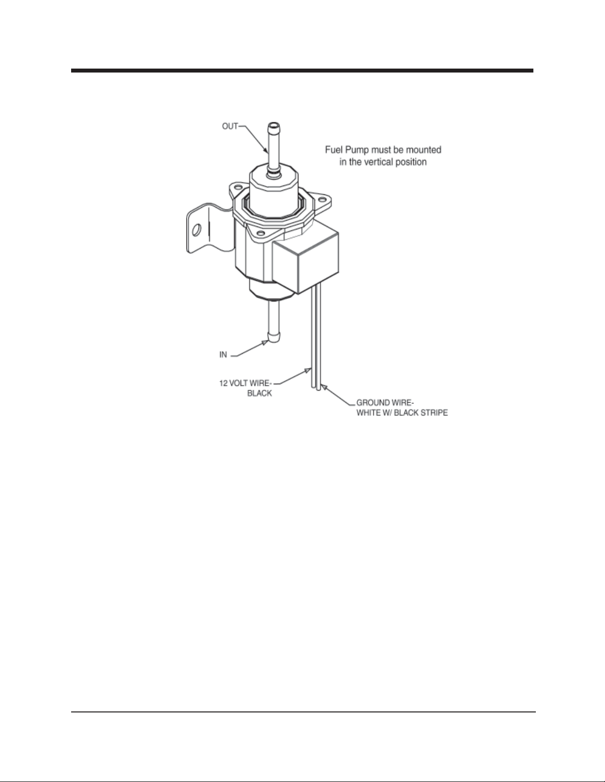
Fuel Pump Assembly
B4627 Rev—
Boxxer 427
HydraMaster Corporation
Page 11

General Information
Section 1-1
his manual contains installation and operation instructions as well as information
T
required for proper maintenance, adjustment and repair of this unit. Since the
first and most important part of repair work is the correct diagnosis of the problem,
component manual troubleshooting charts have been included for your convenience.
Unlike a garden tractor, lawn mower or cement mixer, all having one or two functions
to perform, the truckmounted carpet cleaning plant has many functions to perform
simultaneously.
• The engine has to run at a consistent RPM.
• The vacuum has to pull air and dirty water back from cleaning site.
• The water pump provides stable pressure at proper water flow for cleaning.
• The chemical has to be injected into the water stream at the right
concentration.
• The heating system must maintain proper heat.
• The vacuum tank must store dirty water until drained.
As you can see, it is not just a turnkey operation with one thing to worry about, Does
it start?
HydraMaster Corporation
Page 12

Page 1-2 Boxxer 427
!
WARNING
The manufacturer uses this symbol throughout the manual to warn of possible
injury or death.
!
CAUTION
This symbol is used to warn of possible equipment damage.
Hours Telephone Numbers
Monday - Friday (425) 775-7276 Parts
8:00 am to 5:00 pm (425) 775-7275 Service
PACIFIC STANDARD TIME (800) 426-4225 Parts / Service FAX
HydraMaster Corporation
Page 13

Boxxer 427 Page 1-3
Precautions
lthough this unit has been factory adjusted, it may require additional adjustments
A
to achieve optimum performance, for instance altitude may require carburetor
adjustment and ambient temperatures may require heat control adjustment. When
required, consult an authorized representative.
!
CAUTION
THROUGH-FLOOR DRILLING: Be cautious when drilling holes through the van
floor. Many vans have critical components mounted directly below the van floor
that could be damaged by a misplaced drill bit. (See Product Support Bulletins
92102, 94062 and 94063 at the end of the manual.)
!
CAUTION
ENGINE COOLING: Units employing internal combustion engines must not be
enclosed within a van with doors and windows closed. Excessive temperatures
within the engine will result in premature engine failure and a compromise of
applicable warranty.
!
CAUTION
LEVEL OPERATION: During operation, van or trailer must be parked on level
ground not to exceed + or - 10 degrees. Failure to insure proper leveling may
prevent proper internal lubrication of engine, vacuum and/or high pressure components.
!
WARNING
MOVING PARTS: Never touch any part of the machine that is in motion. Severe
bodily injury may result.
!
WARNING
The machine cannot be run in the IDLE position for cleaning upholstery, carpet or
floor extraction. This will void the warranty.
HydraMaster Corporation
Page 14

Page 1-4 Boxxer 427
!
CAUTION
ACID RINSE AGENTS: The increased demand for “clear water” rinsing results in
the need for special care when using these acid based chemicals in your equipment. The negative side of these products is the corrosive effects the acid can
have on metals, including swivels, pumps, heat exchangers, etc.
HydraMaster’s ClearWater Rinse has been formulated to protect vital compo-
nents. HydraMaster will not warranty parts that have been damaged from using
unprotected acid products that have obviously caused failures.
!
CAUTION
HARD WATER PROTECTION: Failure to take appropriate measures to prevent
scale build up can result in system failure and loss of warranty on affected parts.
Test the water in your immediate and surrounding areas with hard water test
strips. Assume all water obtained from wells is hard. If you are operating in a
“Hard Water Area” (3.5 grains or more per gallon), use a water softening system.
!
CAUTION
FREEZE PROTECTION: There is often little warning before a cold spell. There-
fore, not protecting this equipment from freezing will result in costly downtime.
Placing an electric heater in the truck or parking the truck indoors will help to
insure against freezing, but should not be the primary method of freeze protection.
!
CAUTION
EXHAUST SYSTEM: Do not allow flammable material (i.e. oil, fuel, plastic or
wood products) to come in contact with the exhaust system.
!
WARNING
HOT SURFACES: During the operation of this equipment, many surfaces on the
machine will become very hot. When near the van for any reason care must be
taken not to touch any hot surface, such as heater, engine, exhaust, etc.
HydraMaster Corporation
Page 15

Boxxer 427 Page 1-5
!
WARNING
HEARING PROTECTION: The Occupational Safety and Health Administration
(OSHA) recommends the use of hearing protection when a technician is exposed
to an average of 85 decibels (this is an average of exposure over an 8 hour
period). This equipment can produce 85 decibels to a distance of 10 feet. Please
check with your local state agencies to see if OSHA standards apply to your
application.
!
WARNING
NO SMOKING: It is unsafe to smoke in or around the vehicle.
!
WARNING
CARBON MONOXIDE: This unit generates toxic fumes. Position the vehicle so
that the fumes will be directed away from the job site. Do not park where
exhaust fumes can enter a building through open doors, windows, air conditioning units or kitchen fans.
!
WARNING
TOXIC FUMES: Do not occupy the vehicle when the cleaning equipment is
operating. Toxic fumes may accumulate inside a stationary vehicle.
!
WARNING
ENGINE EXHAUST: The engine exhaust from this product contains chemicals
known to the State of California to cause cancer, birth defects or other reproductive harm.
!
WARNING
PORTABLE GAS TANK: Never operate this machine with a portable gas can
inside the truck. Doing so increases the risk of a fire or explosion.
!
WARNING
PORTABLE PROPANE TANK: Do not use a portable tank inside of the truck or
van. It is dangerous and illegal in most states.
HydraMaster Corporation
Page 16

Page 1-6 Boxxer 427
!
WARNING
TRANSPORTATION OF FUEL CONTAINERS: Transportation in a vehicle of any
vented fuel container that presently has or has ever contained a flammable liquid
is strictly forbidden by HydraMaster Corporation and by federal and state regulation.
!
CAUTION
The use of some chemicals through your mobile carpet cleaning plant can seriously damage the internal plumbing, high-pressure pump, chemical pump and
heat exchangers. These harmful chemicals include concentrated acid (see the
pH chart at the end of this section), solvents (including d-Limonene), and some
paint, oil and grease removers with a high concentration of solvents.
HydraMaster Corporation
Page 17

Boxxer 427 Page 1-7
System Operation
he Boxxer heat exchanger system is a highly engineered cleaning plant designed
T
by HydraMaster Corporation. The system utilizes a dynamic heating system com-
prised of two separate exhaust heat exchangers for capturing “free heat.”
The water flow is as follows:
Water is fed into the machine under tap pressure and it flows through the
water conditioner to the water box. The solution is then picked up by the high
pressure pump and pressurized to the desired level. The water then splits flow,
as demanded by the technician.
The majority of the water flows to the bypass valve assembly, then back to the
water box. The water demanded by the technician flows from the water pump
through the blower exhaust heat exchanger then through the engine exhaust
heat exchanger and out to the cleaning tool.
When the cleaning solution reaches a preset high temperature, it is released
from the system and directed to the recovery tank. Then cool water enters
the system to regulate the temperature. When equipped with an engine
exhaust diverter, the diverter bypasses the heat from the exhaust heat
exchanger and simultaneously releases water from the system and directs it to
the recovery tank.
As there is no guess work in the manufacture of these highly advanced cleaning
plants, there must be none in preparing it to get the job done in the field. It is the
purpose of this manual to help you properly understand, maintain and service your
cleaning plant. Follow the directions carefully and you will be rewarded with years of
profitable, trouble-free operation.
It is imperative that no section be overlooked when preparing for operation of this
equipment.
HydraMaster Corporation
Page 18

Page 1-8 Boxxer 427
Machine Specifications
Frame: 26"W x 45"L x 41"H
Aluminum Cast with Baked-on Epoxy Finish
Weight: 807 lbs.
Engine: Vanguard 27HP Briggs and Stratton
Pressurized Oil System
Spin-on Filter, Oil Cooler and Oil PSI Protection Switch
Ignition: Electronic, Keystart
Vacuum Blower: Dominator 4007, Tuthill/M-D Tri-Lobe,
Pump: Comet FW5530S, 55 GPM Hot Seals, 3000 PSI
Chemical System: Last-Step Chemical
Operating Pressure: Up to 1,200 PSI
Heating System: 1 Water to Water Copper Shell and Tube Heat Exchanger
1 Copper Cross Flow Heat Exchanger Blower/Engine
Exhaust
Instruments: Water Pressure Gauge, Liquid Filled, 0-1500 PSI
Hour Meter, Machine Runtime
Keyed Ignition, Start/Stop
Chemical Flowmeter, Clear Acrylic, 0-10 GPH
Vacuum Gauge
Temperature Gauge
HydraMaster Corporation
Page 19

Boxxer 427 Page 1-9
Recovery Tank: 70 Gallon Aluminum, Epoxy Finish
Cleaning Wand: Stainless Steel
Replaceable Grip
Rebuildable Solution Valve
High Pressure Hose: 4" High Temperature Lined/Vinyl Covered
Hose Rated to 2250 PSI
Vacuum Hose: 2" Reinforced, 12" Reinforced.
Standard Equipment: Machine Power Console
Full Instrumentation
Tuthill/M-D Tri-Lobe Vacuum Blower
BoxxerTM Water Heating Package
Vacuum Recovery Tank
Carpet Cleaning Wand
Chemical Jug
150 ft, 2" Vacuum Hose
10 ft, 1-2" Wand Whip Line
150 ft, Super Flex Solution Line
Battery Box
Van Decal Package
Van Installation Kit
Operation Manual
HydraMaster Jacket
HydraMaster Corporation
Page 20

Page 1-10 Boxxer 427
Spare Parts Recommendation
owntime in the unit can be very expensive, because your truckmounted unit is
capable of generating several hundred dollars per day. In order to minimize such
D
downtime, it is strongly recommended by the manufacturer that you purchase and
keep in your truck the parts listed below.
Parts Orders
To expedite your parts needs, please call your sales representative. In most in-
stances, he either stocks or has access to parts through a regional service center. If
further assistance is needed, contact the factory and coordinate your needs. If this
becomes necessary, always indicate the method of shipment you desire, i.e. UPS,
Blue Label, Air Freight, Air Express, etc.
HydraMaster Parts Dept. Phone .................. (425) 775-7276
HydraMaster Parts Dept. Toll Free Fax......... 1-800-426-4225
Spare Parts List (078-340)
PART NO DESCRIPTION QTY
010-054 Belt, A38 Pump 1
046-010 Diaphragm, Chemical Pump 1
049-002 Filter, Fuel 1
049-008 Filter, S/S Vacuum Pump, 22”1
049-014 Filter, Vanguard Oil 2
049-016 Filter, ¼” Replacement Y 1
049-023 Screen, Garden Hose 1
TBD Filter, Vanguard Air 1
049-118 Filter, 4” s/s 1
049-030 Filter Bag, 92+ Truck Mount 2
052-050 Quick Connect, 440 Male 3
052-051 Quick Connect, 440 Female 2
052-052 Quick Connect, 660 Male 1
052-053 Quick Connect, 660 Female 1
HydraMaster Corporation
Page 21

Boxxer 427 Page 1-11
Spare Parts List (078-340)
PART NO DESCRIPTION QTY
056-001 Fuse, 10 amp 2
056-008 Fuse, 15 amp 2
056-010 Fuse, 25 amp 1
074-007 Gauge, Hi PSI (0-1500) 1
074-032 Meter, Chemical Flow 1
TBD Kit, Seal & Spring Hi PSI 1
TBD Kit, Comet Seal 1
106-016 Plug, Vanguard Spark 2
106-045 50 Series Element 8
157-080 Switch, s/s Float 1
157-040 Rocker
157-022 Switch, Relay 2
169-017 Valve, 3-way Chemical 1
169-022 Valve, 1½” Full Port 1
169-155 Check Valve, Last-Step Chemical 2
169-160 Valve, 2-way Chemical Metering 1
180-004 Orifice, Primary 1
NOTE:
Engine Oil: 30 weight motor oil with a minimum standard of SE, SF, SG.
Blower OIl: 40 weight non detergent
Pump Oil: 40 weight non-detergent
HydraMaster Corporation
Page 22

Page 1-12 Boxxer 427
Responsibilities
he Purchaser’s responsibilities are:
T
Prior to arrival of unit, install s” exterior plywood flooring in the vehicle and cover it
with artificial turf or apply a spray-on coating such as Rhino-lining
!
CAUTION
In Dodge vans the fuel tanks are located directly against the floor.Caution must
be used when drilling any holes through the floor. (See Product Support Bulletin 94062 at the end of this manual.)
To purchase heavy duty 24- 60 amp hour battery and have the battery ‘slow’ charge
if new.
TM
to the van floor.
!
CAUTION
If the battery is not fully charged, damage can occur to the engine charging regulator.
Reading of owner’s manual: It is the purchaser’s responsibility to read the unit
operation manual and to familiarize himself with the information contained therein.
Special attention should be paid to all Cautions and Warnings.
The Sales Representative’s responsibilities are:
ACCEPTANCE OF SHIPMENT:
1. If the unit shows any outward signs of damage, do not sign the delivery
receipt until you have closely inspected the unit and noted any damage on
the delivery receipt.
2. The salesman from whom you purchased your unit is responsible for super
vising the correct installation of the unit in your vehicle and thoroughly
training you in its operation, maintenance and precautions.
HydraMaster Corporation
Page 23

Boxxer 427 Page 1-13
CORRECT INSTALLATION INCLUDES:
• Vehicle of proper load carrying capacity (recommendation: 3/4 ton).
• Installation of a safe fuel tap system and through-floor fittings as approved
by Hydramaster
• Placing the unit and recovery tank in your vehicle and securing them
with bolts or tie down cleats.
• Connecting gasoline lines.
• Connecting the battery.
• Checking the pump, vacuum blower and engine oil levels prior to
staring the unit.
• Starting the unit to check the engine and see that all systems
function normally.
• Checking all hoses, wands, etc. for correct operation.
TRAINING:
• A thorough review of the operation manual with purchaser.
Instruction and familiarization in:
• How to correctly start up and shut down the unit.
• How to correctly clean with the unit.
• Where and how often to check and change component oil levels.
• How the unit’s systems work.
• How to troubleshoot the unit.
• How to do basic repairs.
• Safety precautions and their importance.
• Freezing damage and how to avoid it.
• Hard water damage and how to avoid it.
• A thorough review of the unit warranty and warranty procedures.
• A thorough review of hard water precautions and warnings.
• How to determine hard water areas.
• Use of water softening systems.
HydraMaster Corporation
Page 24
Page 1-14 Boxxer 427
Vehicle Preparation
hen selecting a truck, remember the preferable vehicle for a Boxxer 427
W
capacity. If a fresh water tank is added, a three quarter ton or larger capacity van,
with a 2,400 pound payload capacity, is required.
TRUCK PREPARATION
The manufacturer recommends the installation of a spray-on bed liner in the vehicle
prior to installation of machine.
installation is a cargo van with a heavy-duty suspension package and a half ton
!
CAUTION
Be cautious when drilling any holes through the van floor. Many vans have
critical components mounted directly below the van floor that could be
damaged by a misplaced drill bit. (See Product Support Bulletins 92101, 94062,
and 94063 at the end of this manual.)
This provides ‘metal to cushion’ mounting rather than ‘metal to metal’ and makes for
an atractive van interior. It is highly recommended to install roof vents in vehicles
operated in hot weather locations. Roof vent positions are shown in Figure 1-1.
Figure 1-1 Roof Vent
HydraMaster Corporation
Page 25
Boxxer 427 Page 1-15
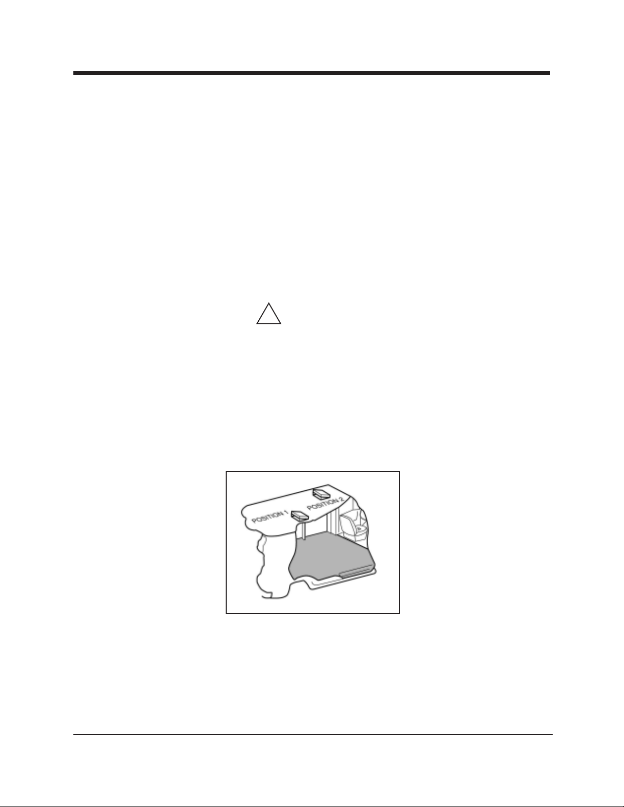
PLACEMENT OF UNIT IN VEHICLE
There are two recommended unit placements:
SIDE DOOR:
Most installations are side door. This provides rear access for accessories and hoses
as well as unobstructed access to the component/working side of the
machine, thus making it a bit easier to perform maintenance and/or repair without
removing the unit from the truck.
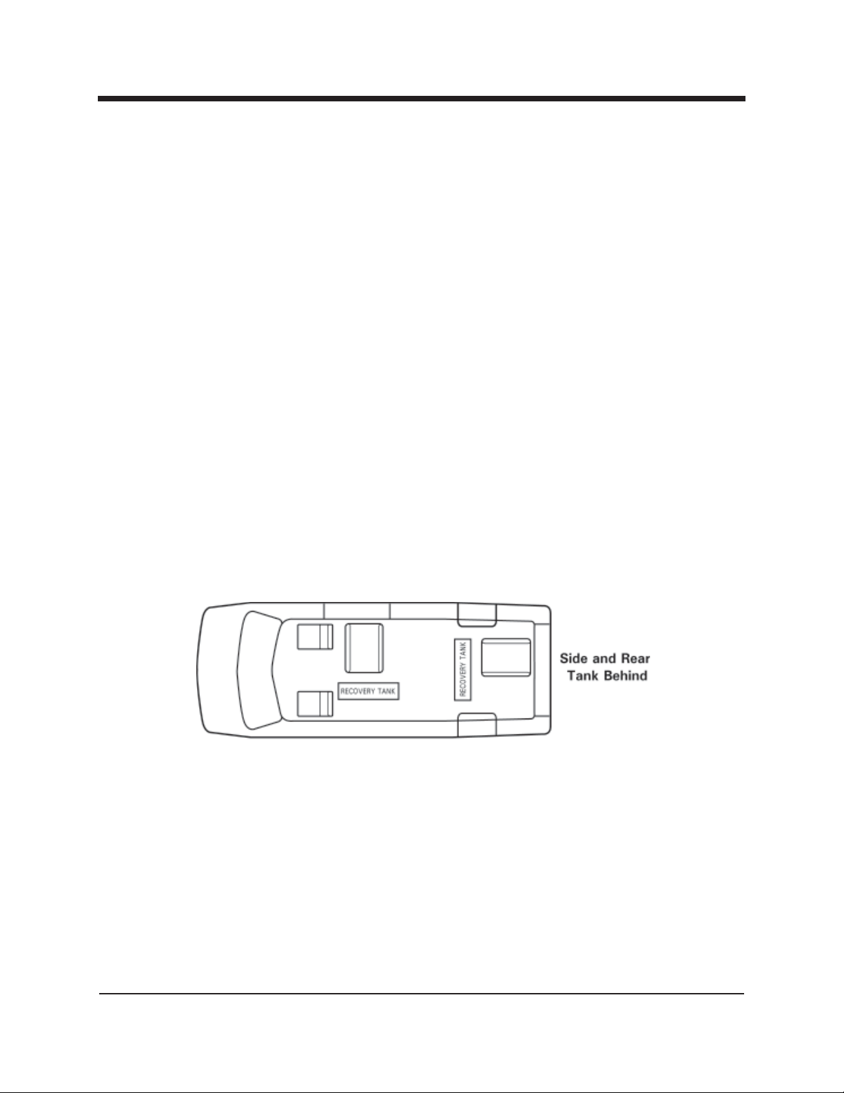
REAR DOOR:
Although this location partly limits working access, it does direct the noise away from
the cleaning site. Some cleaners in the colder areas prefer this location because it
puts the weight over the rear wheels for better traction in ice and snow. Rear mounting requires the unit to be slid to the right side as far as possible.
This not only provides adequate working space on the component side of the unit but
also improves weight distribution inside the van (engine and component weight line
up over drive shaft). Also, it is physically easier to load the unit into the rear door due
to the height of the van bed.
Figure 1-3 Recommended Placement
HydraMaster Corporation
Page 26
Page 1-16 Boxxer 427
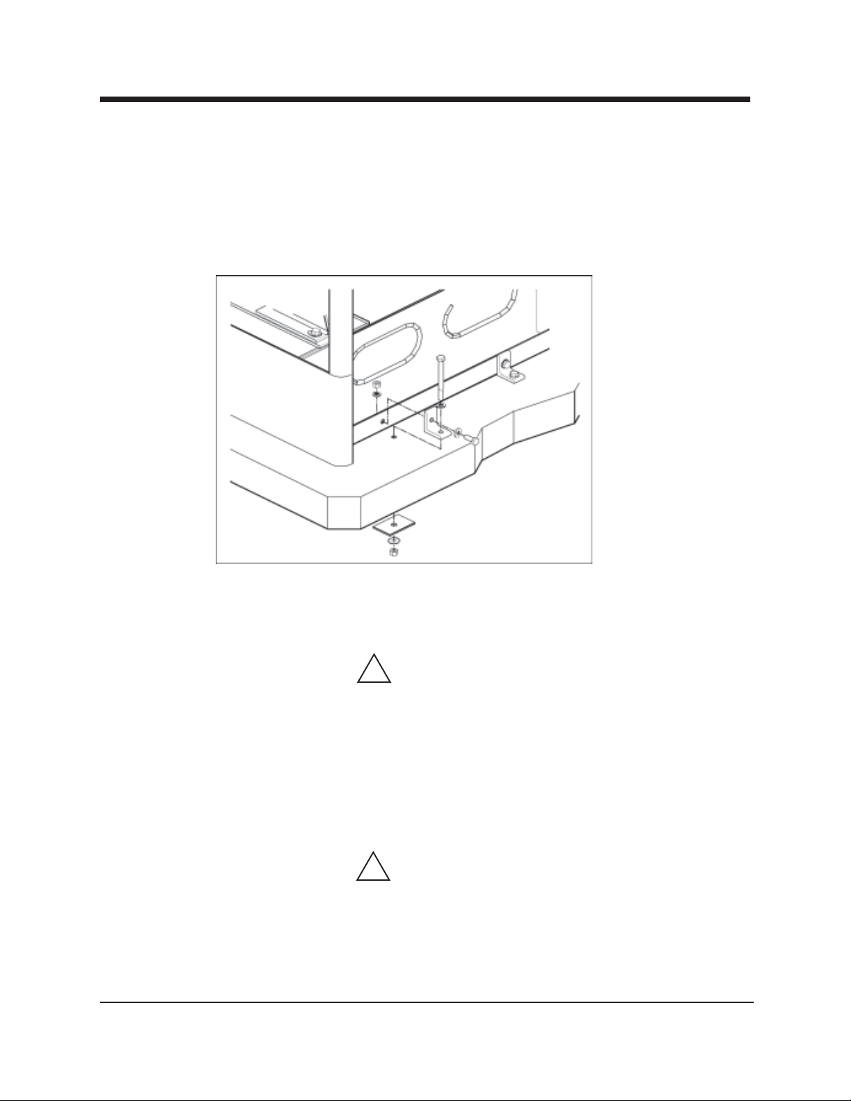
Machine Tie Down Cleats
Secure the machine to the floor of the van with the four tie down cleats provided.
This safety measure will ensure that the machine will not slide inside the van. See the
following illustration for the correct installation.
Figure 1-4 Installation Using Tie-down Cleats
Ensure that the machine is well secured to the floor of the van with the hardware
supplied. A sudden or crash stop will cause the machine to rocket forward. Protect
yourself and the machine. SECURE IT!
!
WARNING
It is recommended by the manufacturer that the exhaust from the front of the
machine be vented down under the truck to prevent carbon monoxide from
entering the job site. Always park the truck so the exhaust is blowing away
from the job site.
The manufacturer also recommends the installation of aluminum vents in the
truck roof to allow heat to escape.
!
WARNING
Never operate this machine with a portable gas can inside the truck. Doing so
increases the risk of a fire or explosion.
Mount a fire extinguisher just inside the rear or side door for emergencies.
HydraMaster Corporation
Page 27

Boxxer 427 Page 1-17
!
WARNING
Do not use a portable propane tank inside of the truck or van. It is dangerous
and illegal in most states.
!
WARNING
Transportation in a vehicle of any vented fuel container that presently holds or
has ever held a flammable liquid is strictly forbidden by HydraMaster Corporation and by federal and state regulation.
!
WARNING
The engine exhaust from this product contains chemicals known to the State
of California to cause cancer, birth defects or other reproductive harm.
HydraMaster Corporation
Page 28

Page 1-18 Boxxer 427
High Altitude Operation
Preparation
o have your machine run at it’s peak performance; you may have to make adjust
T
ments depending on the elevation. Elevation plays a key role in how the machine
will operate.
The factory setting of the machine is set for elevations from 0—3,000 feet. Any
time the machine is operated above 3,000 feet there are two areas on the machine
the may need adjustment.
The first area is the carburetor jet. The higher the elevation, the less air is provided
to the fuel mixture. This will make the engine run ‘rich’, and, in turn will result in
the loss of power, excessive heat in the exhaust, and carbon buildup in the exhaust
and heat exchanger system. The jet sizes vary per engine and elevation. Consult
HydraMaster to obtain proper jet size.
The second area that may need adjustment is the heat control system. The heat
control system is also optimized to 0-3,000 feet. At higher altitudes the boiling
point of water is lowered. In turn, this can cause the water box to boil and the
high pressure pump to cavitate. The heat control system settings will have to be
adjusted to compensate for the elevation. These settings will vary according to
elevation. Contact HydraMaster to obtain the recommended settings.
HydraMaster Corporation
Page 29

Boxxer 427 Page 1-19
Local Water Precautions
he quality of water varies greatly. Many areas have an excess of minerals in the
water which results in what is commonly called “hard water.” These minerals
T
tend to adhere to the insides of heater coils and other parts of the machines causing
damage and a loss of cleaning effectiveness. This influences the reliability and efficiency of equipment in direct proportion to the level of hardness.
HARD WATER ADVISORY
HydraMaster recognizes that any hard water deposits which might occur within the
water system of our truckmounts is a serious problem. The precision technology of
truckmount heat exchanger systems is intolerant of any foreign material. Hard water
deposits will ultimately decrease the performance of the system and are expected to
seriously lower the reliability of the machine.
To validate a machine’s warranty, HydraMaster requires that all machines operating
in designated ”Hard Water Areas” (3.5 grains or more per gallon) be fitted with a
water softening system or a properly installed magnetic-type de-scaler must be used
and maintained. Periodic de-scaling or acid-rinsing alone is not adequate in these
areas.
HydraMaster does not recommend any particular type or brand, however the relative
effectiveness of some types of magnetic de-scalers or softeners may require additional periodic use of de-scaling agents.
HydraMaster also recommends, in the strongest possible terms, that machines in all
areas be fitted with a water softening system for improved operation and reliability.
HydraMaster has included five hard water test strips with your machine. These can
be used to test the water in your immediate and surrounding areas as they can vary
greatly. Assume all water obtained from wells is hard.
!
CAUTION
Failure to take appropriate measures to prevent scale build up can result in
system failure and loss of warranty on affected parts.
HydraMaster Corporation
Page 30

Page 1-20 Boxxer 427
HARD WATER AREA MAP
The following map defines areas in the United States which compromise fluid related
components such as hoses, fittings, heaters, pumps, valves and water cooled engines. For other countries, hard water area maps can be obtained from geological
societies.
WATER SOFTENER
Cleaning efficiency and equipment life is increased, chemical use decreased, and the
appearance of cleaned carpets enhanced when water softeners are incorporated in
hard water areas. The manufacturer strongly urges the use of water softener units in
areas exceeding 32 grains per gallon. Failure to use a water softener in these areas
will invalidate the machine’s warranty. Using a hard water area map as a reference,
determine the quality of water in your area and take action immediately, if necessary.
Reports from several of our machine users commending the results of the use of
water softeners in conjunction with their machines prompts us to recommend the
procedure to everyone in a “hard water” area.
The relatively low cost of a water softener service is more than made up for by an
increased life of machine parts, reduced chemical costs and continued cleaning efficiency. The water softener will also increase the effectiveness of the cleaning chemicals, therefore less chemical will be needed.
Contact a water softener distributor in your area for information on the rental of a
simple water treatment unit to carry in your truck. Be sure to change the water
softener in accordance with the capability of the softener. For example: If the
softener will treat 900 gallons of water and the machine uses an average of 30
gallons per hour, for an average of 5 hours a day, this equals 150 gallons per day. In
6 days the machine would use 900 gallons of water. Therefore, the softener would
need to be changed every 6 working days for maximum softening.
WASTE WATER DISPOSAL ADVISORY
There are laws in most communities prohibiting the dumping of recovered “gray”
water from carpet cleaning in any place but a sanitary treatment system.
HydraMaster Corporation
Page 31

Boxxer 427 Page 1-21
This cleaning rinse water, recovered into your unit’s vacuum tank, contains materials
such as detergents. These must be processed before being safe for streams, rivers
and reservoirs.
IN ACCORDANCE WITH THE EPA, STATE AND LOCAL LAWS, DO NOT
DISPOSE OF WASTE WATER INTO GUTTERS, STORM DRAINS,
STREAMS, RESERVOIRS, ETC.
In most cases, an acceptable method of waste water disposal is to discharge into a
municipal sewage treatment system after first filtering out solid material such as
carpet fiber. Access to the sanitary system can be obtained through a toilet, laundry
drain, RV dump, etc. Permission should first be obtained from any concerned party or
agency.
One disposal method which usually complies with the law is to accumulate the waste
water and haul it to an appropriate dump site. Another solution to the disposal
problem is to equip yourself with an Automatic Pump-Out System. These systems
are designed to remove waste water from the extractor’s recovery system and
actively pump the water through hoses to a suitable disposal drain. Properly
designed, they will continuously monitor the level of waste water and pump it out
simultaneously to the cleaning operation. The hidden benefit of this process is that
the technician does not have to stop his cleaning to empty the recovery tank.
HydraMaster makes an A.P.O. System available which can be ordered with new
equipment or installed later.
The penalties for noncompliance can be serious. Always check local laws and regulations to be sure you are in compliance.
HydraMaster Corporation
Page 32

Page 1-22 Boxxer 427
This page intentionally left blank
HydraMaster Corporation
Page 33

Boxxer 427 Page 1-23
Figure 1-5 Hard Water Map
HydraMaster Corporation
Page 34

Boxxer 427 Page 1-25
Machine Assemblies
and Parts Lists
Figure 1-6 Machine Assembly - Front View - Left Side
D-5570 Rev B
5
2
1
3
8
HydraMaster Corporation
7
4
7
8
Page 35

Page 1-26 Boxxer 427
Figure 1-7 Machine Assembly - Front View - Right Side
D-5570 Rev B
6
HydraMaster Corporation
Page 36

Boxxer 427 Page 1-27
Figure 1-8 Machine Assembly - Rear View - Right Side
D-5570 Rev B
HydraMaster Corporation
Page 37

Page 1-28 Boxxer 427
Machine Assembly Parts List
Item Part Number Description Qty
1 610-001-033 Assembly, Frame - Boxxer 427 (Fig. 1-9 - 1-11) 1
2 610-050-033 Assembly, Top Cover - Boxxer 427 (Fig. 1-31) 1
3 000-041-424 Cover, Lower Left Side - Rear - Boxxer 427 1
4 000-041-426 Cover, Lower Left Side - Front - Boxxer 427 1
5 610-050-033 Assembly, Machine Left Side Cover (Fig. 1-33) 1
6 610-050-033 Assembly, Machine Right Side Cover (Fig. 1-32) 1
7 000-174-001 Washer, #10 Flat 10
8 000-143-126 Screw, #10-24UNC x 0.50" Lg. Hex Head 10
HydraMaster Corporation
Page 38

Boxxer 427 Page 1-29
Figure 1-9 Frame Assembly - Front View - Left Side
D-5571 Rev D
HydraMaster Corporation
Page 39

Page 1-30 Boxxer 427
Figure 1-10 Frame Assembly - Front View - Right Side
D-5571 Rev D
16
2
8
15
HIDDEN
22
6
1110
9 11
12
19
10
ITEM 3 SUPRESSED IN THIS VIEW
HydraMaster Corporation
Page 40

Boxxer 427 Page 1-31
Figure 1-11 Frame Assembly - Rear View - Left Side
D-5571 Rev D
171819
15
2
16
18
17
16
16
19
15
3
13
4
5
14
HydraMaster Corporation
1
12
13
14
20
21
12
Page 41

Page 1-32 Boxxer 427
Frame Assembly Parts List
Item Part Number Description Qty
1 000-055-168 Frame, Steel - Welded - Boxxer 427 1
2 610-003-033 Assembly, Engine - Boxxer 427 (Fig. 1-12 - 1-13) 1
3 610-002-033 Assembly, Blower - Boxxer 427 (Fig. 1-16) 1
4 610-020-033 Assembly, Dash Upper - Boxxer 427 (Fig. 1-21 - 1-22) 1
5 610-019-033 Assembly, Dash Lower - Boxxer 427 (Fig. 1-24 - 1-25) 1
6 610-006-033 Assembly, Coolant Heat Exchanger (Fig. 1-29) 1
7 610-005-033 Assembly, Blower Heat Exchanger (Fig. 1-30) 1
8 610-003-033 Assembly, Exhaust - Boxxer 427 (Fig. 1-14) 1
9 000-093-092 Silencer, Boxxer 427 - Weldment 1
10 000-143-002 Screw, 1/4"-20UNC x 1.00" Lg. Hex Head 4
11 000-174-019 Washer, 1/4" Lock 4
12 000-020-063 Bushing, Snap, 0.55" O.D. x 0.312" I.D. 4
13 000-027-109 Cap, 2" x 2" Black 2
14 000-027-110 Cap, 2" x 3" Black 2
15 000-033-057 Clamp, 1" Cushion Loop 3
16 000-033-053 Clamp, 1-1/2" Cushion Loop 5
17 000-155-054 Spring, #10 Belleville Washer 9
18 000-174-001 Washer, #10 Flat 9
19 000-143-126 Screw, #10-24UNC x 0.50" Lg. Hex Head 9
20 000-105-012 Plate, Machine Serial I.D. 1
21 000-140-001 Rivet, 1/8" x 1/4" Aluminum 2
22 000-033-067 Clamp, 2" Cushion Loop 1
HydraMaster Corporation
Page 42

Boxxer 427 Page 1-33
Figure 1-12 Engine Assembly - Rear View
D-5572 Rev G
29
2
22
19
18
7
5
6
4
5
34
21
28
23
21
20
21
33
32
31
25
24
26
27
14
13
11
9
8
9
13
10
3
9
10
13
12
HydraMaster Corporation
Page 43

Page 1-34 Boxxer 427
Figure 1-13 Engine Assembly - Front View
D-5572 Rev G
16
17
1
31
15
35
36
Engine Assembly Parts List
Item Part Number Description Qty
1 000-047-026 Engine, Briggs & Stratton 27HP 1
2 000-042-011 Housing, Air Cleaner - Daihatsu Engine 1
3 000-092-011 Mount, Engine 27 B&S - Boxxer 427 1
4 000-001-033 Adapter, Thermostat Housing 1
5 000-057-050 Gasket, Thermostat Housing Daihatsu Engine 2
HydraMaster Corporation
Page 44

Boxxer 427 Page 1-35
Engine Assembly Parts List
Item Part Number Description Qty
6 000-047-026 Thermostat, Stock B&S 27HP 1
7 000-047-026 Thermostat Housing, B&S 27 HP Stock 1
8 000-174-105 Washer, 1-1/16" I.D. Self Aligning Spherical 2 Pc Set 2
9 000-174-007 Washer, 1/2" Flat 4
10 000-143-567 Screw, 1/2"-13UNC x 2.0" Lg. Hex Head Grd. 8 2
11 000-094-037 Nut, 1/2"-13UNC Hex 2-Way Locking - Z/P 2
12 000-143-568 Screw, 5/16"-18UNC x 2.50" Lg. Hex Head Grade 8 4
13 000-174-004 Washer, 5/16" Flat 8
14 000-094-081 Nut, 5/16"-18UNC Hex 2-Way Locking 4
15 000-033-117 Clamp, 1" Cushion Loop w/ 7/16" Mount Hole 1
16 000-052-063 Bushing, 14mm x 1/4" NPT Engine Oil Drain Adapter 1
17 000-068-746 Hose, Engine Oil Drain - Boxxer 427 1
18 000-174-019 Washer, 1/4" Lock 2
19 000-143-569 Screw, 6mm x 85mm Lg. Hex Head 2
20 000-154-144 Spacer, Air Cleaner - Boxxer 427 2
21 000-174-049 Washer, 5/16" Flat 6
22 000-068-702 Hose, 1-3/4" I.D. 1
23 000-106-007 Plug, 1/4" NPT Allen Head 1
24 000-052-108 Insert, #F25 (1/8" FPT x 5/16" Barb) 1
25 000-106-009 Plug, 1/8" NPT Allen Head 1
26 000-033-005 Clamp, Size #5 Hose 1
27 000-033-057 Clamp, 1" Cushion Loop 1
28 000-143-184 Screw, 8mm x 45mm Lg. Hex Head Grd. 10.9 2
29 000-049-063 Filter, Replacement - Engine Air Daihatsu 1
30 000-049-014 Filter, 16HP Oil - All B & S 1
31 000-111-171 Pump, B&S 27 HP Water 1
32 000-056-006 Fuse Holder, Inline Weather Proof 1
33 000-056-011 Fuse, 30 AMP Plug In 1
34 000-113-007 Radiator, 27 B & S Engine 1
35 000-052-293 Insert, #23 (1/8" NPT x 3/16" Barb) 1
HydraMaster Corporation
Page 45

Page 1-36 Boxxer 427
Figure 1-14 Exhaust Assembly
D-5580 Rev C
25
18
25
18
26
29
28
30
28
20
15
26
22
21
19
12
27
13
11
14
10
1
9
6
8
7
12
13
4
5
19
21
24
11
11
23
13
12
21
19
31
20
16
31
17
3
2
20
16
17
HydraMaster Corporation
Page 46

Boxxer 427 Page 1-37
Exhaust Assembly Parts List
Item Part Number Description Qty
1 Fig. 1-15 Assembly, Diverter Valve Actuator - Boxxer 427 1
2 000-125-214 Tube, Diverter To Outlet Plenum - Boxxer 427 1
3 000-001-116 Adapter, 1.50" F Slip To Flare - Boxxer 427 1
4 000-094-027 Nut, #10-24UNC Hex 2
5 000-155-030 Spring, Leaf 1
6 000-138-010 Retainer, Leaf Spring 1
7 000-174-001 Washer, #10 Flat 2
8 000-143-132 Screw, #10-24UNC x 0.75" Lg. Hex Head 2
9 000-015-631 Bracket, Air Cylinder Actuation 1
10 000-103-014 Pin, 1/8 x 3/4" Roll 1
11 000-057-146 Gasket, Four Hole Exhaust Diverter 3
12 000-143-572 Screw, 5/16"-18UNC x 5/8" Lg. Hex Grd. 5 12
13 000-174-069 Washer, 5/16" Inconel Belleville, Diverter Valve 12
14 000-169-045 Valve, Cast Exhaust Diverter 1
15 000-090-059 Manifold, Boxxer 427 Engine Exhaust B&S 27 Hp 1
16 000-057-177 Gasket, Exhaust Donut 1.50" 2
17 000-125-128 Tube, 1-3/8" OD x 1/8" Wall x 7/8" Long 2
18 000-174-049 Washer, 5/16" Flat 4
19 000-094-117 Nut, 5/16"-18UNC Hex Spiralock 6
20 000-143-124 Screw, 5/16"-18UNC x 1.75" Lg. Hex Head 6
21 000-033-068 Clamp, 1-1/2" Muffler 3
22 000-093-100 Muffler- Weldment - Boxxer 427 1
23 000-001-102 Adapter, Exhaust Flange To 1.50" M Slip 1
24 000-052-642 Elbow, 1.50 With Flanges 1
25 000-057-194 Gasket, B&S 27 Hp Exhaust Manifold - Boxxer 427 2
26 000-143-187 Screw, 8mm x 25mm Lg. Grade. 10.9 Hex Head 4
27 000-001-099 Adapter, Exhaust Flange To Ø1.50" F Slip - Boxxer 421 1
28 000-174-166 Washer, 5/16" Tab 4
29 000-094-012 Nut, 5/16-18"UNC Hex 2
30 000-057-199 Gasket, Exhaust Donut 1
31 000-094-081 Nut, 5/16"-18UNC Hex 2-Way Locking 4
HydraMaster Corporation
Page 47

Page 1-38 Boxxer 427
Figure 1-15 Diverter Valve Actuator Assembly
C-5584 Rev B
5
9
8
10
1
6
4
3
2
7
Diverter Valve Actuator Assembly Parts List
Item Part Number Description Qty
1 000-169-169 Valve, Air Cylinder 1
2 000-015-926 Bracket, Air Cylinder Extension - Welded - Boxxer 427 1
3 000-094-092 Nut, 7/16"-20UNF Hex Jam 1
4 000-052-550 Elbow, 1/8" NPT x 3/16" Barb 2
5 000-015-750 Bracket, Air Cylinder Mount - Inner 1
6 000-015-748 Bracket, Air Cylinder Mount - Outer 1
7 000-143-573 Screw, 5/16-18 Shoulder, 3/8" Dia x 1/2" 1
8 000-174-003 Washer, 1/4" Flat 4
9 000-143-180 Screw, 1/4"20UNC x 2.75" Lg. Hex Head 2
10 000-094-071 Nut, 1/4"-20UNC Hex Nylock Half 2
HydraMaster Corporation
Page 48

Boxxer 427 Page 1-39
Figure 1-16 Blower Assembly
D-5573 Rev H
2
4
3
1
15
14
9
10
5
12
14
13
28
21
8
18
17
19
20
21711 24
28
26
10
22
25
23
22
31
6
27
9
10
16
22
10
29
30
Blower Assembly Parts List
Item Part Number Description Qty
1 000-111-167 Blower, MD 4007 C-Face Dual Shaft - Boxxer 427 1
2 Fig. 1-17 Assembly, Pump - Boxxer 427 1
HydraMaster Corporation
Page 49

Page 1-40 Boxxer 427
Blower Assembly Parts List
Item Part Number Description Qty
3 Fig. 1-20 Assembly, Water Box - Boxxer 427 1
4 Fig. 1-19 Assembly, Pump Mounting Bracket - Boxxer 427 1
5 000-015-814 Bracket, Dominator Mounting - Boxxer 421 1
6 000-042-061 Housing, Bell - Boxxer 427 1
7 000-109-112 Pulley, 3.50" Pump Drive 1
8 000-001-115 Adapter, Blower Flange To 3" M Slip - Boxxer 427 1
9 000-174-057 Washer, 3/8" Lock 5
10 000-143-018 Screw, 3/8"-16UNC x 1.00" Lg. Grade 8 10
11 000-010-123 Belt, EPDM 40" A-Section 1
12 000-174-105 Washer, 1-1/16" I.D. Self Aligning Spherical 2 Pc. Set 1
13 000-143-567 Screw, 1/2"-13UNC x 2.0" Lg. Hex HD Grd 8 Bo 1
14 000-174-007 Washer, 1/2" Flat 2
15 000-094-037 Nut, 1/2"-13UNC Hex 2-Way Locking - Z/P 1
16 000-015-897 Bracket, Water Box Support 1
17 000-143-001 Screw, 1/4"-20UNC x 0.75" Lg. Hex Head 6
18 000-174-019 Washer, 1/4" Lock 6
19 000-068-398 Hose, 3" I.D. x 3 Ply Silcone 1
20 000-033-013 Clamp, Size #48 Hose 2
21 000-052-142 Elbow, 3/8" FPT x FPT 2
22 000-174-021 Washer, 3/8" Lock 11
23 000-143-025 Screw, 3/8"-16UNC x 1.25" Lg. Hex Head Grd 8 3
24 000-020-019 Bushing, #H x 7/8" Bore 1
25 000-143-200 Screw, 3/8"-16UNC x 1.50" Lg. Grade 8 4
26 000-174-004 Washer, 5/16" Flat 3
27 000-174-032 Washer, 3/8" Flat 2
28 000-052-074 Nipple, 3/8" NPT Hex 2
29 000-152-010 Sleeve, 50 Series Split (Replacement) 1
30 000-078-424 Kit, Metal Ring Retainer 3 Pc. (Replacement) 1
31 000-039-053 Coupler, 50 Series 1
HydraMaster Corporation
Page 50

Boxxer 427 Page 1-41
Figure 1-17 Pump Assembly
D-5574 Rev D
1
13
28
27
11
17
21
9
18
16
15
22
10
24
23
29
24
23
5
3
2
12
HydraMaster Corporation
7
8
6
19
23
25
4
262014
24
Page 51

Page 1-42 Boxxer 427
Pump Assembly Parts List
Item Part Number Description Qty
1 000-111-041 Pump, Hydra Pump V - Boxxer 427 1
2 000-052-084 Elbow, 1/8" NPT Street 1
3 000-052-099 Insert, #26 (1/8" NPT x 3/8" Barb) 1
4 Fig. 1-18 Assembly, Chemical Pump - Boxxer 427 1
5 000-052-531 Elbow, 1/8" NPT x 1/4" SAE 1
6 000-169-176 Valve, 2 Way Chemical Pump 1
7 000-001-096 Adapter, Chemical Pump To Comet Pump 1
8 000-097-057 O-Ring, Adapter - Chemical Pump 1
9 000-036-008 Clutch, Electric Pump 1
10 000-052-085 Elbow, 1/4" NPT Street 2
11 000-105-312 Plate, Clutch Mount - Hydra Pump V - Boxxer 427 1
12 000-052-086 Elbow, 3/8" NPT Street 1
13 000-052-128 Nipple, 3/8" NPT x 3/8" Male Propane 1
14 000-052-517 Nipple, 1/4" NPT Close 1
15 000-135-052 Regulator, Hi PSI Snubber 1
16 000-052-527 Nipple, 1/4" SAE x 1/4" NPT 1
17 000-143-221 Screw, M6-1 x 14mm Lg. Hex Head 4
18 000-143-141 Screw, 1/4"-20UNC x 1/2" Lg. Whiz Lock 4
19 000-114-017 Rail, HydraPump V Mounting - Boxxer 427 1
20 000-068-219 Hose, Spitfire Pump Drain 1
21 000-106-003 Plug, 3/8" NPT Hex 1
22 000-106-004 Plug, 1/2" NPT Hex 1
23 000-174-049 Washer, 5/16" Flat 4
24 000-094-038 Nut, 5/16"-18UNC Nylock 4
25 000-094-013 Nut, 5/16"-24UNF Hex 4
26 - - - Screw, 8mm x 1.0 x 12mm Lg. 4
27 000-154-145 Spacer, Comet Pump Clutch - Boxxer 427 1
28 000-052-753 Insert, #816 (1/2" NPT x 1" Barb) 1
29 000-114-019 Rail, HydraPump V / Chem Pump Mounting - Boxxer 427 1
HydraMaster Corporation
Page 52

Boxxer 427 Page 1-43
Figure 1-18 Chemical Pump Assembly
C-6555 Rev A
2
9
1
OUTLET
7
INLET
10
8
3
5
6
4
9
11
8
10
7
1
Chemical Pump Assembly Parts List
Item Part Number Description Qty
1 000-106-110 Plug, Check Valve - Chemical Pump 2
2 000-064-015 Cover, Chemical Pump 1
3 000-111-030 Body, Chemical Pump 1
4 000-105-071 Mid Plate, Chemical Pump 1
5 000-046-010 Diaphragm, Chemical Pump 1
6 000-097-055 O-Ring, Chemical Pump Midplate An Size -227 Viton 1
7 000-097-056 O-Ring, Check Valve Plug - Chemical Pump 2
8 000-169-155 Valve, Check, - Last Step Chemical Injection 2
9 000-143-152 Screw, 5/16"-24UNF x 1.50" Lg. Socket Head 4
10 000-097-054 O-Ring, Chem. Pump Valve Viton-Parker 2-114 2
11 000-143-574 Screw, 5/16"-24UNF x 2" Lg. Soc. Head Grade L9 2
HydraMaster Corporation
Page 53

Page 1-44 Boxxer 427
Figure 1-19 Pump Mounting Bracket Assembly
D-5766 Rev F
6
3
22
9
11
8
10
7
9
11
10
8
9
11
7
23
13
12
21
9
15
2
20
1
14
2
5
4
17
19
18
17
16
HydraMaster Corporation
Page 54

Boxxer 427 Page 1-45
Pump Mounting Bracket Assembly Parts List
Item Part Number Description Qty
1 000-174-032 Washer, 3/8" Flat 2
2 000-094-014 Nut, 3/8"-16UNC Hex Zinc Plated 2
3 000-174-021 Washer, 3/8" Lock 4
4 000-015-893 Bracket, Pump Mounting - Welded 1
5 000-174-005 Washer, 3/8" Flat 4
6 000-143-139 Screw, 3/8"-16UNC x 4.00 Lg. Grd 8 4
7 000-169-070 Valve, Primary Vac. Solenoid 2
8 000-106-014 Plug, Gearbox Vent 2
9 000-052-106 Insert, 1/8" NPT x 5/32" Barb x 90° 4
10 000-052-293 Insert, #23 (1/8" NPT x 3/16" Barb) 3
11 000-143-047 Screw, #6-32UNC x 7/8" Lg. Pan Head Phillips 4
12 000-143-050 Screw, #8-32UNC x 0.50" Lg. Round Head Phillips 2
13 000-012-001 Block, 4 Lead Electrical Terminal 1
14 000-015-746 Bracket, Pump Idler - Boxxer 421 1
15 000-174-057 Washer, 3/8" Lock 1
16 000-143-041 Screw, 1/2"-13UNC x 2.25" Lg. Hex Head 1
17 000-174-012 Washer, 1/2" SAE H/D Flat 2
18 000-109-093 Pulley, 3" “A” Sect. Ball Bearing - Assembled 1
19 000-154-049 Spacer, Pump Idler Mounting - Boxxer 421 1
20 000-105-207 Plate, Pump Idler Nut - Boxxer 421 1
21 000-108-145 Protector, Drip - Wire Terminal 1
22 Fig. 1-38 Assembly, Vacuum Relief Valve (Collector Box) 1
23 000-057-207 Gasket, Vacuum Relief Valve Plate 1
HydraMaster Corporation
Page 55

Page 1-46 Boxxer 427
Figure 1-20 Water Box Assembly
D-5575 Rev H
3
2
10
8
13
14
16
15
16
26
19
10
5
7
12
27
24
4
19
21
22
23
21
22
23
9
11
20
1
5
6
9
10
17
25
17
10
5
18
HydraMaster Corporation
Page 56

Boxxer 427 Page 1-47
Water Box Assembly Parts List
Item Part Number Description Qty
1 000-159-107 Tank, Poly Water Box - Modified 1
2 000-041-005 Cover, 6" 1
3 000-143-314 Screw, #8 x 1/2" Lg. Pan Head 6
4 000-052-660 Bulkhead, 3/8" FPT x 3/8" FPT 1
5 000-052-086 Elbow, 3/8" NPT Street 3
6 000-052-023 Tee, 3/8" NPT Male Street 1
7 000-052-155 Tee, 3/16" Plastic Vacuum Insert 1
8 000-169-167 Valve, Mechanical Incoming Water - Water Box 1
9 000-052-105 Insert, #68 (3/8" NPT x 1/2" Barb) 2
10 000-174-063 Washer, 1.5" O.D. x 1.073" I.D. x 0.075" Thk. 4
11 000-057-052 Gasket, 1" Garden Hose 1
12 000-005-007 Float, Water Box 1
13 000-143-336 Screw, #10-32UNF x 0.25" Lg. Pan Head Phillips 1
14 000-052-099 Insert, #26 (1/8" NPT x 3/8" Barb) 1
15 000-068-326 Hose, 3/8" I.D. Clear w/ Braid Solution 1
16 000-033-005 Clamp, Size #5 Hose 2
17 000-094-097 Nut,1-14" Brass Water Box 3
18 000-052-662 Nipple, 3/8" NPT x 1/4" M SAE 1
19 000-097-041 O-Ring, 1/2" Bulkhead 2
20 000-015-896 Mount, Water Box - Boxxer 427 1
21 000-174-032 Washer, 3/8" Flat 2
22 000-174-057 Washer, 3/8" Lock 2
23 000-143-017 Screw, 3/8"-16UNC x 0.75" Lg. Hex Head Grd. 8 2
24 000-049-151 Assembly, Diffuser Filter - Boxxer 427 (Fig. 1-41) 1
25 000-050-754 Insert, #F816 (1/2" FPT x 1" Barb) 1
26 000-052-728 Bulkhead, 1/2" FPT x 3/8" FPT 1
27 000-157-0801 Assembly, Float Switch w/ Polyprop. Barrel (Fig. 1-42) 1
HydraMaster Corporation
Page 57

Page 1-48 Boxxer 427
Figure 1-21 Dash Upper Assembly - Front View
D-5576 Rev A
14
10
9
1
6
5
3
12
2
13
10
9
4
7
8
HydraMaster Corporation
Page 58

Boxxer 427 Page 1-49
Figure 1-22 Dash Upper Assembly - Rear View
D-5576 Rev A
16
15
5
HydraMaster Corporation
9
8
11
Page 59

Page 1-50 Boxxer 427
Dash Upper Assembly Parts List
Item Part Number Description Qty
1 000-100-141 Panel, Upper Dash - Boxxer 427 1
2 000-100-145 Panel, Grill - Boxxer 427 1
3 000-157-008 Switch, Ignition 1
4 000-074-018 Meter, Rectangular w/o Bezel 1
5 000-025-002 Cable, Choke (3 Foot) 1
6 000-025-020 Cable, Throttle Kohler 1
7 000-084-011 Light, Red Led Indicator Mini 4
8 610-020-033 Assembly, Dash Guage Panel - Boxxer 427 (Fig. 1-23) 1
9 000-174-001 Washer, #10 Flat 18
10 000-174-014 Washer, #10 Lock 12
11 000-094-034 Nut, #10-24UNC Nylock 6
12 000-131-131 Trimlock, 3/8" x 1/8" Groove 1
13 000-143-134 Screw, #10-24UNC x 1.00" Lg Hex Head 4
14 000-143-126 Screw, #10-24UNC x 0.50" Lg. Hex Head 8
15 000-174-032 Washer, 3/8" Flat 1
16 000-174-057 Washer, 3/8" Lock 1
HydraMaster Corporation
Page 60

Boxxer 427 Page 1-51
Figure 1-23 Dash Guage Panel Assembly
D-5585 Rev C
16
11 12 21
13
1
203
2
17
7
8
18
3
19
23
8
1
7
10
13
14
10
15
2
11 12
21
HydraMaster Corporation
22
10
20
6 5
4
2
9
Page 61

Page 1-52 Boxxer 427
Dash Guage Panel Assembly Parts List
Item Part Number Description Qty
1 000-100-150 Panel, Dash Gauge - Boxxer 427 1
2 000-052-099 Insert, #26 (1/8" NPT x 3/8" Barb) 3
3 000-169-160 Valve, Chemical Metering 1
4 000-052-069 Nipple, 1/8" NPT Hex 1
5 000-169-0171Valve, 3-Way Ball O-Ring Style 1
6 000-052-084 Elbow, 1/8" NPT Street 1
7 000-074-017 Guage, 0-30" Hg Vac. 2 1/2" Hydramaster Face 1
8 000-074-016 Gauge, Temperature 1
9 000-149-551 Thermostat, Potentiometer Dual Controller 1
10 000-094-070 Nut, 5mm Nylock 4
11 000-174-001 Washer, #10 Flat 4
12 000-174-014 Washer, #10 Lock 2
13 000-074-007 Gauge, Pressure (0-1500 Psi) 1
14 000-052-088 Elbow, 1/4" FPT x FPT 1
15 000-052-527 Nipple, 1/4" SAE x 1/4" NPT 1
16 000-157-040 Switch, 20 AMP Rocker 4
17 000-061-056 Knob, Temperature Adjustment 1
18 000-074-030 Meter, Chemical Flow Raw 1
19 000-094-098 Nut, 7/16"-24UNF - 2 Way Metering Valve 1
20 000-052-531 Elbow, 1/8" NPT x 1/4" SAE 2
21 000-143-327 Screw, #10-32UNF x 0.50" Lg. Hex Head 2
22 000-094-002 Nut, #8-32UNC Hex 2
23 000-094-034 Nut, #10-24UNC Nylock 1
HydraMaster Corporation
Page 62

Boxxer 427 Page 1-53
Figure 1-24 Dash Lower Assembly - Front View
D-5577 Rev E
16
1
5
4
18
17
2
9
15
13
9
24
22
21
11
HydraMaster Corporation
Page 63

Page 1-54 Boxxer 427
Figure 1-25 Dash Lower Assembly - Rear View
D-5577 Rev E
12
19
10
8
6
26
8
6
27
7
20
30
18
14
16
21
23
22
28
29
25
15
30
3
32
31
Dash Lower Assembly Parts List
Item Part Number Description Qty
1 000-100-143 Panel, Lower Dash - Boxxer 427 1
2 000-052-272 Cup, Gravity Feed Oil Blower Lubrication Port 1
HydraMaster Corporation
Page 64

Boxxer 427 Page 1-55
Dash Lower Assembly Parts List
Item Part Number Description Qty
3 000-052-096 Insert, #F23 (1/8" FPT x 3/16" Barb) 1
4 000-052-052 Quick Connect, 660 Male w/ Viton Standard 1
5 000-052-051 Quick Connect, 440 Female w/ Epdm O-Ring 2
6 000-052-071 Nipple, 1/4" NPT Hex 2
7 000-174-008 Washer, 5/8" Flat 4
8 000-174-007 Washer, 1/2" Flat 4
9 000-143-126 Screw, #10-24UNC x 0.50" Lg. Hex Head 6
10 000-090-008 Manifold, Hi Pressure 1
11 000-143-542 Screw, 1/4"-28UNF x 0.50" Lg. 2
12 000-106-009 Plug, 1/8" NPT Allen Head 1
13 000-155-053 Spring, 1/4" Belleville Washer 2
14 000-052-105 Insert, #68 (3/8" NPT x 1/2" Barb) 1
15 Fig. 1-27 Assembly, Hi-PSI Manifold 1
16 Fig. 1-26 Assembly, By-Pass Valve 1
17 000-169-064 Valve, 3/8" NPT Full Port Ball 1
18 000-052-104 Insert, #66 (3/8" NPT x 3/8" Barb) 2
19 000-052-527 Nipple, 1/4" SAE x 1/4" NPT 1
20 000-068-017 Hose, 3/8" I.D. Bulk 1
21 610-011-033 Assembly, Electrical Control Panel - Bxr 427 (Fig. 1-28) 1
22 000-174-001 Washer, #10 Flat 8
23 000-094-034 Nut, #10-24UNC Nylock 4
24 000-174-014 Washer, #10 Lock 4
25 000-068-739 Hose, 3/8" x 16" Lg. w/ JIC & NPT Ends 1
26 000-052-074 Nipple, 3/8" NPT Hex 1
27 000-169-186 Valve, 3/8" FPT x 3/8" FPT 100 PSI Check 1
28 000-052-086 Elbow, 3/8" NPT Street 1
29 000-052-528 Nipple, 3/8" M JIC x 3/8" NPT 1
30 000-033-005 Clamp, Size #5 Hose 2
31 000-174-032 Washer, 3/8" Flat 2
32 000-052-084 Elbow, 1/8" NPT Street 1
HydraMaster Corporation
Page 65

Page 1-56 Boxxer 427
Figure 1-26 By-Pass Valve Assembly
C-5581 Rev C
12
11
9
10
13
5
3
4
5
13
1
6
14
9
2
7
8
HydraMaster Corporation
Page 66

Boxxer 427 Page 1-57
By-Pass Valve Assembly Parts List
Item Part Number Description Qty
1 000-052-128 Nipple, 3/8" NPT x 3/8" Male Propane 1
2 000-015-515 Bracket, By-Pass Valve Mounting 1
3 000-169-188 Valve, PSI Regulator 0-1500 PSI - Modified 1
4 000-106-008 Plug, 3/8" NPT Allen Head 1
5 000-052-023 Tee, 3/8" NPT Male Street 2
6 000-052-083 Elbow, 3/8" NPT Street x 45° 1
7 000-052-142 Elbow, 3/8" FPT x FPT 1
8 000-052-104 Insert, #66 (3/8" NPT x 3/8" Barb) 1
9 000-052-086 Elbow, 3/8" NPT Street 2
10 000-052-061 Bushing, 3/8" NPT x 1/4" FPT 1
11 000-052-587 Compression, 3/16" x 1/4" NPT Thermocouple Fitting 1
12 000-149-540 Sensor, RTD Compresion Fitting Style 1
13 000-052-105 Insert, #68 (3/8" NPT x 1/2" Barb) 2
14 000-052-528 Nipple, 3/8" M JIC x 3/8" NPT 1
HydraMaster Corporation
Page 67

Page 1-58 Boxxer 427
Figure 1-27 Hi-PSI Manifold Assembly
C-5582 Rev A
14
10
11
3
13
2
6
12
9
5
8
6
4
7
1
HydraMaster Corporation
Page 68

Boxxer 427 Page 1-59
Hi-PSI Valve Assembly Parts List
Item Part Number Description Qty
1 000-090-057 Manifold, Hi-PSI - Boxxer 427 1
2 000-180-004 Orifice, Set Screw 0.033" 1
3 000-052-423 Bushing, Modified Set Screw Orifice 1
4 000-049-016 Filter, 1/4" NPT Replacement “Y” 1
5 000-052-528 Nipple, 3/8" M JIC x 3/8" NPT 1
6 000-106-111 Plug, 1/2" NPT Allen 2
7 000-155-020 Spring, 0.540 O.D. x 0.041 Wire x 1.00 Lg. 1
8 000-052-023 Tee, 3/8" NPT Male Street 1
9 000-052-061 Bushing, 3/8" NPT x 1/4" FPT 1
10 000-052-082 Elbow, 1/4" NPT Street x 45° 1
11 000-149-540 Sensor, RTD Compresion Fitting Style 1
12 000-149-039 Sender, Temperature 1
13 000-052-587 Compression, 3/16" x 1/4" NPT Thermocouple Fitting 1
14 000-052-527 Nipple, 1/4" SAE x 1/4" NPT 1
HydraMaster Corporation
Page 69

Page 1-60 Boxxer 427
Figure 1-28 Electrical Control Panel Assembly
C-5583 Rev D
13
18
12
11
25
28
16
12
25
12
11
2
27
27
21
22
21
20
21
1215
16
4
6
7
5
19
3
4
17
21
8
26
14
1
10
20
23
24
9
HydraMaster Corporation
Page 70

Boxxer 427 Page 1-61
Electrical Control Panel Assembly Parts List
Item Part Number Description Qty
1 000-100-137 Panel, Electrical Control - Boxxer 427 1
2 000-041-418 Cover, Electrical Control Panel - Boxxer 427 1
3 000-012-010 Block, Terminal 10 Post 1
4 000-157-022 Switch, Relay 2
5 000-084-010 Light, Green LED Indicator Mini 1
6 000-084-011 Light, Red LED Indicator Mini 1
7 000-084-012 Light, Yellow LED Indicator Mini 1
8 000-156-030 Stud, #10-32UNF x 2" Lg. Boxxer Elec. Panel Cover 2
9 000-094-108 Nut, #10-32UNF Wing 2
10 000-074-130 Controller, Temp. Dual Independent 1
11 000-094-034 Nut, #10-24UNC Nylock 2
12 000-174-001 Washer, #10 Flat 4
13 000-060-002 Grommet, Large Wiring 1
14 000-056-030 Diode Panel 1
15 000-033-053 Clamp, 1-1/2" Cushion Loop 1
16 000-143-126 Screw, #10-24UNC x 0.50" Lg. Hex Head 2
17 000-033-067 Clamp, 2" Cushion Loop 1
18 000-094-003 Nut, #10-32UNF Hex 2
19 000-037-011 Connector, “Jumper” Terminal Block 2
20 000-135-004 Diode, Plug In 3
21 000-056-007 Fuse, 10 AMP Plug In 6
22 000-056-010 Fuse, 25 AMP Plug In 1
23 000-174-014 Washer, #10 Lock 4
24 000-143-545 Screw, #8-32UNC x 1.00" Lg. Phillips Head 4
25 000-143-062 Screw, #10-24UNC x 0.75" Lg. Pan Head Phillips 2
26 000-143-534 Screw, #10-24UNC x 1.00" Lg. Pan Head Phillips 2
27 000-094-058 Nut, #10-32 UNF - Nylock 2
28 000-060-014 Grommet, 1.00" I.D. x 1.50" O.D. 1
HydraMaster Corporation
Page 71

Page 1-62 Boxxer 427
Figure 1-29 Coolant Heat Exchanger Assembly
D-5578 Rev A
13
10
13
12
13
11
13
7
2
5
6
3
14
8
1
13
9
13
7
4
3
6
5
HydraMaster Corporation
Page 72

Boxxer 427 Page 1-63
Coolant Heat Exchanger Assembly Parts List
Item Part Number Description Qty
1 000-038-043 Heat Exchanger, Water To Water 1
2 000-052-086 Elbow, 3/8" NPT Street 1
3 000-052-528 Nipple, 3/8" M JIC x 3/8" NPT 2
4 000-052-083 Elbow, 3/8" NPT Street x 45° 1
5 000-143-001 Screw, 1/4"-20UNC x 0.75" Lg. Hex Head 4
6 000-174-019 Washer, 1/4" Lock 4
7 000-052-131 Elbow, 1" NPT x 1" Barb 2
8 000-125-194 Tube, Coolant Heat Exchager To Engine - Boxxer 427 1
9 000-068-250 Hose, 1" I.D. Green Stripe 1
10 000-068-250 Hose, 1" I.D. Green Stripe 1
11 000-068-250 Hose, 1" I.D. Green Stripe 1
12 000-052-648 Tee, 1" Barb x 1" Barb x 1" Barb 1
13 000-033-020 Clamp, Size #16 Hose 6
14 000-108-134 Protector, Coolant Hx Grey Silicone Blanket 1
HydraMaster Corporation
Page 73

Page 1-64 Boxxer 427
Figure 1-30 Blower Heat Exchanger Assembly
D-5579 Rev B
3
5
11
12
11
1
6
3
10 89
11
8
9
10
2
4
7
11
13
2
4
4
HydraMaster Corporation
Page 74

Boxxer 427 Page 1-65
Blower Heat Exchanger Assembly Parts List
Item Part Number Description Qty
1 000-038-055 Core, Blower Heat Exchanger - Boxxer 427 1
2 000-052-528 Nipple, 3/8" M JIC x 3/8" NPT 2
3 000-140-021 Rivet, 1/4" Blind x 0.50" Lg. 32
4 000-052-086 Elbow, 3/8" NPT Street 3
5 000-013-059 Box, Inlet Plenum - Welded - Boxxer 427 1
6 000-013-060 Box, Outlet Plenum - Weldment - Boxxer 427 1
7 000-001-097 Adpater, Exhaust Turndown - Raw 1
8 000-143-002 Screw, 1/4"-20UNC x 1.00" Lg. Hex Head 4
9 000-174-019 Washer, 1/4" Lock 4
10 000-174-002 Washer, 1/4" Flat 4
11 000-033-013 Clamp, Size #48 Hose 4
12 000-068-398 Hose, 3" I.D. x 3 Ply Sil. 1
13 000-068-398 Hose, 3" I.D. x 3 Ply Sil. 1
HydraMaster Corporation
Page 75

Page 1-66 Boxxer 427
Figure 1-31 Top Cover Assembly
D-5586 Rev A
4
5
8
2
7
8
8
5
6
5
8
3
4
5
1
Top Cover Assembly Parts List
Item Part Number Description Qty
1 000-041-416 Cover, Top Machine - Boxxer 427 1
2 000-041-422 Cover, Brow - Boxxer 427 1
3 000-100-153 Panel, Brow End - Weldment - Boxxer 427 1
4 000-143-166 Screw, #10-24UNC x 0.38" Lg. Hex Head 8
5 000-174-001 Washer, #10 Flat 12
6 000-094-034 Nut, #10-24UNC Nylock 4
7 000-143-126 Screw, #10-24UNC x 0.50" Lg. Hex Head 6
8 000-174-036 Washer, #10 Flat Rubber Backed 6
HydraMaster Corporation
Page 76

Boxxer 427 Page 1-67
Figure 1-32 Machine Right Side Cover Assembly
D-5762 Rev -
6
5
1
6
5
4
2
3
4
3
Machine Right Side Cover Assembly Parts List
Item Part Number Description Qty
1 000-041-419 Cover, Right Side Machine - Boxxer 427 1
2 000-105-313 Plate, Hydramaster Name- Roto Tank 1
3 000-174-001 Washer, #10 Flat 2
4 000-143-166 Screw, #10-24UNC x 0.38" Lg. Hex Head 2
5 000-094-034 Nut, #10-24UNC Nylock 2
6 000-089-003 Magnet, Treadmaster 2
HydraMaster Corporation
Page 77

Page 1-68 Boxxer 427
Figure 1-33 Machine Left Side Cover Assembly
D-5587 Rev -
5
6
1
6
5
4
3
2
4
3
Machine Left Side Cover Assembly Parts List
Item Part Number Description Qty
1 000-041-417 Cover, Left Side Machine - Boxxer 427 1
2 000-105-313 Plate, Hydramaster Name- Roto Tank 1
3 000-174-001 Washer, #10 Flat 2
4 000-143-166 Screw, #10-24UNC x 0.38" Lg. Hex Head 2
5 000-094-034 Nut, #10-24UNC Nylock 2
6 000-089-003 Magnet, Treadmaster 2
HydraMaster Corporation
Page 78

Boxxer 427 Page 1-69
Figure 1-34 70 Gallon Universal Recovery Tank Assembly
D-6860 Rev B
43
42
40
8
HIDDEN
HIDDEN
6
41
40
10
39
40
35
1
2
5
11
21
22
29
14
16
15
30
37
31
38
32
28
36
34
35
29
9
13
HIDDEN
24
7
23
27
12
22
25
26
3
4
3
HydraMaster Corporation
17
33
2
19
18
20
Page 79

Page 1-70 Boxxer 427
70 Gallon Univesal Recovery Tank Assembly Parts List
Item Part Number Description Qty
1 000-159-128 Tank, 70 Gallon Universal Recovery - Weldment 1
2 610-003-015 Assembly, Cover - Dual Vac. (Fig. 1-35) 1
3 000-157-090 Float, Lever Switch 2
4 000-079-091 Kit, Dura-Flow APO - Production (Firg. 1-39) 1
5 000-049-152 Filter, Recovery Tank Basket 1
6 000-049-153 Filter, Flat - Recovery Tank 1
7 000-012-002 Block, 6 Post Terminal 1
8 000-015-932 Bracket, Flat Filter Securing - Universal Recovery Tank 1
9 000-049-154 Deflector, Air - Univeral Recovery Tank 1
10 000-057-206 Gasket, Adapter - Universal Recovery Tank 1
11 000-140-023 Rivet, AB8-6A Aluminum Pop 6
12 000-143-051 Screw, #8-32UNC x 0.75" Lg. Binder Head Phillips 2
13 000-094-059 Nut, #8-32UNF Nylock 2
14 000-086-008 Latch, Bungie 1
15 000-143-539 Screw, #6-32UNC x 0.50" Lg. Button Head Allen 2
16 000-094-063 Nut, #6-32UNC Nylock 2
17 000-106-019 Plug, 1-1/2" NPT 1
18 000-052-763 Nipple, 1-1/2" LPS Close s/s 1
19 000-169-022 Valve, 1-1/2" Full Port Ball 1
20 000-052-226 Insert,1-1/2" NPT x 1-1/2" Barb (Grey) 1
21 000-052-082 Elbow, 1/4" NPT Street x 45° 1
22 000-052-102 Insert, #46 (1/4" NPT x 3/8" Barb) 2
23 000-052-085 Elbow, 1/4" NPT Street 1
24 000-052-090 Tee, 1/4" NPT Branch M-F-F 1
25 000-169-120 Valve, Chemical & Hi-Temp Solenoid - 12 Volt 1
26 000-052-105 Insert, #68 (3/8" NPT x 1/2" Barb) 1
27 000-052-073 Nipple, 3/8" NPT x 1/4" NPT Hex 1
28 000-081-241 Label, Maintenance & Lubrication Schedule (Part of set) 1
29 000-174-029 Washer, 3/8" Rubber Back 2
30 000-094-034 Nut, #10-24UNC Nylock 4
31 000-033-023 Clamp, 3/4" Nylon Hose 2
HydraMaster Corporation
Page 80

Boxxer 427 Page 1-71
70 Gallon Universal Recovery Tank Assembly Parts List
Item Part Number Description Qty
32 000-143-132 Screw, #10-24UNC x 0.75" Lg. Hex Head 2
33 000-106-049 Plug, 1" NPT Allen Head 1
34 000-174-060 Washer, 1/4" Flat Rubber Backed 4
35 000-143-002 Screw, 1/4"-20UNC x 1.00" Lg. Hex Head 8
36 000-094-113 Nut, 1/4"-20UNC Neoprene Wellnut 4
37 000-174-036 Washer, #10 Flat Rubber Backed 2
38 000-174-001 Washer, #10 Flat 2
39 000-001-135 Adapter, Tank To Ø3.0" x 90° Blower Hose - Universal 1
40 000-174-003 Washer, 1/4" Flat 10
41 000-094-009 Nut, 1/4"-20UNC Hex Nylock 4
42 000-174-019 Washer, 1/4" Lock 2
43 000-143-333 Screw, 1/4"-20UNC x 0.50" Lg. Hex Head 2
HydraMaster Corporation
Page 81

Page 1-72 Boxxer 427
Figure 1-35 70 Gallon Universal Recovery Tank Cover Assembly
D-6890 Rev -
1
11
2
3
5
8
10
9
6
3
7
4
70 Gallon Universal Recovery Tank Cover Assembly Parts List
Item Part Number Description Qty
1 000-041-444 Cover, Dual Vac. 70 Gallon Universal Recovery Tank - 1
2 000-052-222 Elbow, 2" Barb x 2" FPT 2
3 000-057-202 Gasket, End - Recovery Tank 2
4 000-057-203 Gasket, Middle - Recovery Tank 2
5 000-057-204 Gasket, Side - Recovery Tank - 70 Gallon 2
6 000-057-015 Gasket, 1-1/2" Bulkhead Fitting 2
7 000-052-219 Adapter, 2" NPT x 2" F Slip 2
8 000-086-008 Latch, Bungie - Strike 1
9 000-143-539 Screw, #6-32UNC x 0.50" Lg. Button Head Allen 2
10 000-094-063 Nut, #6-32UNC Nylock 2
11 000-078-039 Vacuum Inlet Stopper Assembly - Recovery Tank 1
HydraMaster Corporation
Page 82

Boxxer 427 Page 1-73
Figure 1-36 100 Gallon Universal Recovery Tank w/ APO Assembly
D-6983 Rev A
12
11
HIDDEN
HIDDEN
HIDDEN
2
28
19
20
9
7
29
20
32
20
31
5
35
44
20
31
6
29
25
26
15
HIDDEN
18
HIDDEN
30
13
16
17
8
14
37
36
40
26
38
39
43
42
31
33
4
27
10
34
HIDDEN
30
HIDDEN
13
3
HIDDEN
34
30
HIDDEN
21
24 23 22
41
13
HydraMaster Corporation
10
3
1
Page 83

Page 1-74 Boxxer 427
100 Gallon Universal Recovery Tank Assembly Parts List
Item Part Number Description Qty
1 000-159-129 Tank, 100 Gallon Universal Recovery - Weldment 1
2 Fig -1-37 Assembly, Recovery Tank Cover - 100 Gallon 1
3 000-157-090 Float, Lever Switch 2
4 000-079-091 Kit, Dura-Flow APO - Production (Fig 1-39) 1
5 000-105-336 Plate, Vacuum Port Cover - 100 Gallon Universal Recov 1
6 000-049-152 Filter, Recovery Tank Basket 1
7 000-049-153 Filter, Flat - Recovery Tank 1
8 000-012-002 Block, 6 Post Terminal 1
9 000-015-932 Bracket, Flat Filter Securing - Universal Recovery Tank 1
10 000-033-023 Clamp, 3/4" Nylon Hose 2
11 000-049-154 Deflector, Air - Univeral Recovery Tank 1
12 000-140-023 Rivet, AB8-6A Aluminum Pop 6
13 000-143-126 Screw, #10-24UNC x 0.50" Lg. Hex Head 5
14 000-143-051 Screw, #8-32UNC x 0.75" Lg. Binder Head Phillips 2
15 000-094-059 Nut, #8-32UNF Nylock 2
16 000-086-008 Latch, Bungie 1
17 000-143-539 Screw, #6-32UNC x 0.50" Lg. Button Head Allen 2
18 000-094-063 Nut, #6-32UNC Nylock 2
19 000-174-019 Washer, 1/4" Lock 2
20 000-174-003 Washer, 1/4" Flat 18
21 000-106-019 Plug, 1-1/2" NPT 1
22 000-052-763 Nipple, 1-1/2" LPS Close s/s 1
23 000-169-022 Valve, 1-1/2" Full Port Ball 1
24 000-052-226 Insert,1-1/2" NPT x 1-1/2" Barb (Grey) 1
25 000-052-082 Elbow, 1/4" NPT Street x 45° 1
26 000-052-102 Insert, #46 (1/4" NPT x 3/8" Barb) 2
27 000-081-241 Label, Maintenance & Lubrication Schedule (Part of set) 1
28 000-143-333 Screw, 1/4"-20UNC x 0.50" Lg. Hex Head 2
29 000-174-029 Washer, 3/8" Rubber Back 2
30 000-174-036 Washer, #10 Flat Rubber Backed 5
HydraMaster Corporation
Page 84

Boxxer 427 Page 1-75
100 Gallon Universal Recovery Tank Assembly Parts List
Item Part Number Description Qty
31 000-143-002 Screw, 1/4"-20UNC x 1.00" Lg. Hex Head 12
32 000-094-009 Nut, 1/4"-20UNC Hex Nylock 8
33 000-166-002 Tray, Soap Jug - Weldment 1
34 000-094-034 Nut, #10-24UNC Nylock 2
35 000-057-206 Gasket, Adapter - Universal Recovery Tank 2
36 000-052-085 Elbow, 1/4" NPT Street 1
37 000-052-090 Tee, 1/4" NPT Branch M-F-F 1
38 000-169-120 Valve, Chemical & Hi-Temp Solenoid - 12 Volt 1
39 000-052-105 Insert, #68 (3/8" NPT x 1/2" Barb) 1
40 000-052-073 Nipple, 3/8" NPT x 1/4" NPT Hex 1
41 000-106-049 Plug, 1" NPT Allen Head 1
42 000-174-060 Washer, 1/4" Flat Rubber Backed 4
43 000-094-113 Nut, 1/4"-20UNC Neoprene Wellnut 4
44 000-001-135 Adapter, Tank To Ø3.0" x 90° Blower Hose - Universal 1
HydraMaster Corporation
Page 85

Page 1-76 Boxxer 427
Figure 1-37 100 Gallon Universal Recovery Tank Cover Assembly
D-6919 Rev -
8
2
5
6
7
9
1
3
4
10
11
9
100 Gallon Universal Recovery Tank Cover Assembly Parts List
Item Part Number Description Qty
1 000-041-447 Cover, 100 Gallon Universal Recovery Tank - Weldment 1
2 000-078-039 Vacuum Inlet Stopper Assembly - Recovery Tank 1
3 000-057-015 Gasket, 1-1/2" Bulkhead Fitting 2
4 000-052-219 Adapter, 2" NPT x 2" F Slip 2
5 000-143-539 Screw, #6-32UNC x 0.50" Lg. Button Head Allen 2
6 000-086-008 Latch, Bungie - Strike 1
7 000-094-063 Nut, #6-32UNC Nylock 2
8 000-052-222 Elbow, 2" Barb x 2" FPT 2
9 000-057-202 Gasket, End - Recovery Tank 2
10 000-057-203 Gasket, Middle - Recovery Tank 3
11 000-057-205 Gasket, Side - Recovery Tank - 100 Gallon 2
HydraMaster Corporation
Page 86

Boxxer 427 Page 1-77
Figure 1-38 Vacuum Relief Valve Assembly (Collector Box)
C-7156 Rev -
7
5
3
11
9
1
4
10
8 2
6
HydraMaster Corporation
Page 87

Page 1-78 Boxxer 427
Vacuum Relief Valve Assembly (Collector Box) Parts List
Item Part Number Description Qty
1 000-015-182 Bracket, Vacuum Relief Valve 1
2 000-027-032 Cap, Vacuum Releif Valve 1
3 000-125-111 Pipe, Vacuum Relief Spring Guide 1
4 000-105-337 Plate, Vacuum Relief Valve Mounting 1
5 000-155-026 Spring, Vacuum Relief 1
6 000-143-198 Screw, 3/8"-16UNC x 4" Lg. Hex Head Full Thread 1
7 000-094-077 Nut, 3/8"-16UNC x 1.00" O.D. Knurled 2
8 000-094-101 Nut, 3/8"-16UNC Hex Jam 1
9 000-143-001 Screw, 1/4"-20UNC x 0.75" Lg. Hex Head 4
10 000-174-003 Washer, 1/4" Flat 4
11 000-174-019 Washer, 1/4" Lock 4
HydraMaster Corporation
Page 88

Boxxer 427 Page 1-79
Figure 1-39 Dura-Flow APO Pump Assembly
D-5654 Rev E
2
38
5
6
7
7
6
13
4
8
6
12
14
4
16
17
15
22
HydraMaster Corporation
1
5
16
17
9
18
10
19
21
20
Page 89

Page 1-80 Boxxer 427
Dura-Flow APO Pump Assembly Parts List
Item Part Number Description Qty
1 000-111-169 Assembly, APO Pump - Jabsco 1
2 000-091-042 Motor, Bison 438 Series 1
3 000-015-891 Bracket, APO Clamp 1
4 000-015-890 Bracket, Tank Mounted APO Support 1
5 000-143-566 Screw, 1/4-28UNF x 0.75" Lg. Socket Head 4
6 000-143-074 Screw, 1/4"-20UNC x 0.50" Lg. Hex Head Self-Tapping 4
7 000-174-002 Washer, 1/4" Flat 4
8 000-061-131 Knob, Handle - Rdm 2
9 000-052-723 Fitting, 1" NPT Cam Lock - Banjo 100F 1
10 000-052-724 Fitting, 1" NPT Cam Lock - Banjo 100B 1
11 000-157-022 Switch, Relay 1
12 000-012-011 Block, 6 Post 1
13 000-094-027 Nut, #10-24UNC Hex 1
14 000-143-532 Screw,#6-32UNC x 5/8" Lg. Socket Head 2
15 000-068-069 Hose, 3/4" I.D. Weatherhead - Blue - Bulk. 1
16 000-033-026 Clamp, Size #10 Hose 2
17 000-052-338 Insert, #1212 (3/4" NPT x 3/4" Barb) 2
18 000-169-009 Valve, 3/4" FPT Swing Check 1
19 000-052-281 Nipple, 3/4" NPT x 3/4" Male Garden Hose 1
20 000-057-055 Gasket, Garden Hose 1
21 000-027-014 Cap, Garden Hose 1
22 000-052-425 Bushing, 1" NPT x 3/4" FPT 1
HydraMaster Corporation
Page 90

Boxxer 427 Page 1-81
Figure 1-40 Chemical Jug Tray Assembly
C-4945 Rev C
9
2
7
5
4
10
16
10
11
17
18
7
6
8
3
10
19
12
14
1
13
4
15
5
HydraMaster Corporation
Page 91

Page 1-82 Boxxer 427
Chemical Jug Tray Assembly Parts List
Item Part Number Description Qty
1 000-166-021 Tray, Chemical Jug - Outer - Weldment 1
2 000-166-025 Tray, Chemical Jug - Inner 1
3 000-078-039 Vacuum Inlet Stopper 1
4 000-143-001 Screw, 1/4"-20UNC x 0.75" Lg. Hex Head 2
5 000-174-019 Washer, 1/4" Lock 2
6 000-169-022 Valve, 1-1/2" Full Port Ball 1
7 000-052-226 Insert,1-1/2" NPT x 1-1/2" Barb (Grey) 2
8 000-052-182 Nipple, 1-1/2" NPT Close Galvanized 1
9 000-159-016 Jug, 5 Gallon Plastic Chemical - Standard 1
10 000-174-003 Washer, 1/4" Flat 4
11 000-015-720 Bracket, Apo Outlet Mounting - Weldment 1
12 000-027-014 Cap, Garden Hose 1
13 000-052-338 Insert, #1212 (3/4" NPT x 3/4" Barb) 1
14 000-057-055 Gasket, Garden Hose 1
15 000-169-009 Valve, 3/4" FPT Swing Check 1
16 000-174-050 Washer, 1" Flat 1
17 000-174-063 Washer, 1.5" O.D. x 1.073" I.D. x 0.075" Thk. 1
18 000-052-281 Nipple, 3/4" NPT x 3/4" Male Garden Hose 1
19 000-094-009 Nut, 1/4"-20UNC Hex Nylock 2
HydraMaster Corporation
Page 92

Boxxer 427 Page 1-83
Figure 1-41 Diffueser Filter Assembly
C-6554 Rev -
5
4
3
1
4
2
Diffuser Filter Assembly Parts List
Item Part Number Description Qty
1 000-052-074 Nipple, 3/8" NPT Hex 1
2 000-033-131 Clamp, Diffuser - Boxxer 427 1
3 000-125-222 Tube, Diffuser - Boxxer 427 1
4 000-027-115 Cap, 2" PVC Modified For Diffuser - Boxxer 427 2
5 000-052-104 Insert, #66 (3/8" NPT x 3/8" Barb) 1
HydraMaster Corporation
Page 93

Page 1-84 Boxxer 427
Figure 1-42 Float Switch w/ Polypropylene Barrel Assembly
C-6549 Rev -
4
3
2
4
1
Float Switch w/ Polypropylene Barrel Assembly Parts List
Item Part Number Description Qty
1 - - - Stem, Float Switch 1
2 000-005-011 Float, Polypropylene Replacement- Boxxer 427 1
3 000-108-110 Shield, Poly Float Splash 1
4 000-139-010 Ring, Snap Ring (E-Clip) x 5/16" 2
HydraMaster Corporation
Page 94

Boxxer 427 Page 1-85
(To be Added)
HydraMaster Corporation
Page 95

Page 1-86 Boxxer 427
(To be Added)
HydraMaster Corporation
Page 96

Boxxer 427 Page 2-1
Cleaning and Chemicals
Boxxer 427
Section 2-1
our mobile carpet cleaning plant has been engineered using the latest and most
sophisticated technology available to produce the finest carpet cleaning results
Y
possible. Despite this, however, it remains only a tool of the carpet cleaning trade,
and it can produce only as good a job as the person operating it.
PRECAUTIONS
There are no short cuts to good carpet cleaning. It requires time, cleaning knowledge
and the use of good chemicals. Therefore, the manufacturer recommends the use of
spotting agents and traffic lane cleaners, as required, prior to the actual cleaning of
carpeting.
The use of some chemicals through your mobile carpet cleaning plant can seriously
damage the internal plumbing, high pressure pump and heater. These harmful
chemicals include concentrated acid (see the pH chart at the end of this section),
solvents, and some paint, oil, and grease removers with a high concentration of
solvents.
The manufacturer recommends only the use of chemicals containing rust and corrosion inhibitors and water softening agents to prevent chemical buildup which may
lead to component failure and warranty invalidation.
!
CAUTION
The increased demand for “clear water” rinsing results in the need for special
care when using these acid based chemicals in your equipment. The negative
side of these products is the corrosive effects the acid can have on metals,
including swivels, pumps, heat exchangers, etc.
HydraMaster’s ClearWater Rinse has been formulated to protect vital components.
HydraMaster will not warranty parts that have been damaged from using unprotected
acid products that have obviously caused failures.
HydraMaster Corporation
Page 97

Page 2-2 Boxxer 427
CLEANING STROKE PROCEDURE
Purpose:
To eliminate excess moisture remaining in the carpet fiber and the saw tooth
appearance which results from diagonal movement of the cleaning tool on all types
of carpet.
Procedure:
Always move the cleaning tool in smooth, forward and backward strokes. Apply
slight pressure to the forward stroke while the solution is injected into the carpet.
When extracting (drying), apply firm pressure on the forward stroke to ensure a positive “lock” for the vacuum and minimize the “hopping” effect resulting on carpet that
is not smooth. During the forward and reverse strokes, movement to the right or left
should only be accomplished at the extreme rear of the stroke. Overlapping is also
important to ensure even application of solution and prevent saturation when cleaning wand is stopped twice at the same point at the rear of the cleaning stroke. This
is illustrated at the end of this section.
Failure to adopt this procedure can result in increased chance of “clean streaks,” fiber
shrinkage, brown-out and longer drying periods.
OVER-WETTING
Over-wetting is annoying to all concerned, and sometimes leaves a bad impression of
the cleaning process used.
THESE ARE SEVERAL AREAS THAT WILL CAUSE OVER-WETTING
1. Too few vacuum strokes or improper saw-tooth vacuum strokes as shown
in the following illustration.
2. Obstructed, cut or kinked hoses.
3. Vacuum tank drain valve left partially open.
4. Clogged vacuum blower filter or vacuum tank lid not sealing properly.
5. Cleaning a heavily foam-saturated carpet without defoamer. (We
recommend crystal type.)
HydraMaster Corporation
Page 98

Boxxer 427 Page 2-3
HydraMaster Corporation
Page 99

Page 2-4 Boxxer 427
This page intentionally left blank
HydraMaster Corporation
Page 100

Boxxer 427 Page 3-1
Operating Instructions
Boxxer 427
Section 3-1
START UP
1. Perform daily and periodic maintenance as specified in this Owner’s Manual.
2. Connect all required hoses, including a garden hose for water supply.
3. Connect the cleaning tool to the length of hose required to perform
the cleaning.
!
CAUTION
Water box must be full prior to ignition.
!
WARNING
The machine cannot be run in the “IDLE” position for cleaning upholstery, carpet or
floor extraction. This will void the warranty.
NOTE: In order to achieve consistent adjustable temperatures, an operating pressure
of 200 PSI must be maintained.
Note: Never run machine on any speed other than full throttle. Running at any
other speed will void the warranty.
Carpet or Hard Surface Cleaning
1. Start the engine with throttle cable in “IDLE” position.
Allow machine to run in idle for 2 - 3 minutes to warm up.
2. Connect hoses.
3. Connect wand or tool.
4. Pull THROTTLE to “HIGH” position.
5. If used, turn PUMP IN switch to “ON” .
6. Turn PUMP switch to “ON” .
7. Turn DIVERTER switch to “ON” .
8. Set temperature to desired level.
9. If used, turn PUMP OUT switch to “ON” .
HydraMaster Corporation
 Loading...