

Page 1
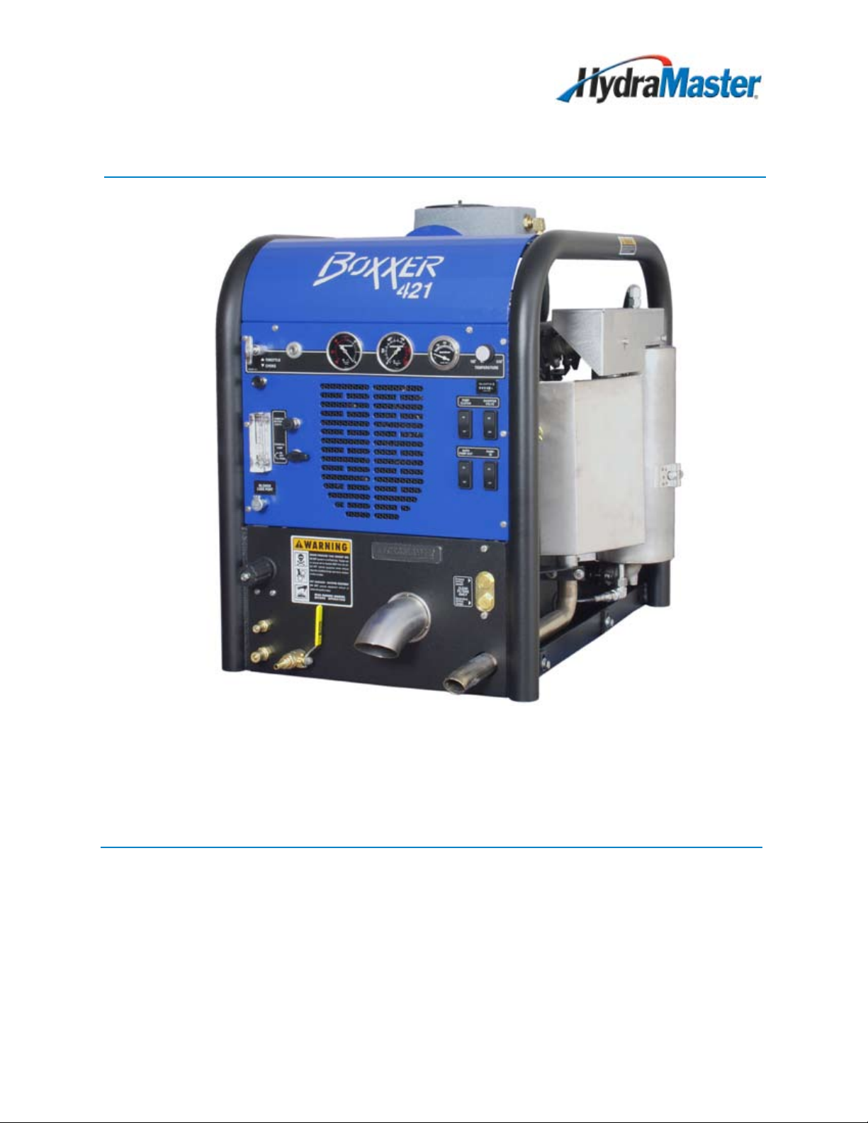
Boxxer 421
Owner’s Manual
HydraMaster
11015 47th Avenue West
Mukilteo, Washington 98275
MAN-45049 Rev. 0, March 23, 2012
No part of this manual may be reproduced or used in any form or by any means (i.e. graphic, electronic, photocopying or electronic
retrieval systems) without the express written permission of HydraMaster. Specications and information in this document are
subject to change without prior notice.
(182-
065
-D)
All rights reserved. © 2012 HydraMaster
Page 2

Page 3

Table of Contents
GENERAL INFORMATION ........................................................................... SECTION 1
System Concept ...................................................................................... 1-2
Contact Information ................................................................................. 1-3
Warnings, Cautions and Notices ............................................................. 1-4
Responsibilities ....................................................................................... 1-8
Machine Specications ........................................................................... 1-11
High Altitude Operation ........................................................................... 1-13
Local Water Precautions ......................................................................... 1-13
INSTALLATION INFORMATION ................................................................... SECTION 2
Orientation of Fuel Pump ........................................................................ 2-4
CLEANING INFORMATION ......................................................................... SECTION 3
Precautions ............................................................................................. 3-2
Preparing the Carpet for Extraction......................................................... 3-2
Rinse and Recover.................................................................................. 3-3
Overwetting ............................................................................................. 3-3
Streaking ................................................................................................. 3-3
Cleaning Tool Tips ................................................................................... 3-4
OPERATING INSTRUCTIONS ..................................................................... SECTION 4
Exhaust Diverter System......................................................................... 4-2
Start Up ................................................................................................... 4-5
Carpet or Hard Surface Cleaning ............................................................ 4-6
Upholstery Cleaning ................................................................................ 4-7
Flood Extraction ...................................................................................... 4-8
Shut Down............................................................................................... 4-9
MACHINE MAINTENANCE ......................................................................... SECTION 5
Operational Maintenance ........................................................................ 5-2
Overall Machine Maintenance................................................................. 5-3
High Pressure Pump ............................................................................... 5-5
Vacuum System ...................................................................................... 5-9
Freeze Guard .......................................................................................... 5-11
WATER AND CHEMICAL SYSTEM ............................................................. SECTION 6
Water and Chemical Flow Operation ...................................................... 6-1
Before Cleaning ...................................................................................... 6-1
Chemical System Maintenance............................................................... 6-2
Troubleshooting ...................................................................................... 6-3
i: Boxxer 421 Owner’s Manual
Page 4

ELECTRICAL SYSTEM ................................................................................ SECTION 7
Troubleshooting ...................................................................................... 7-6
SYSTEMS TROUBLESHOOTING ............................................................... SECTION 8
High Pressure Pump ............................................................................... 8-6
Vacuum ................................................................................................... 8-9
ASSEMBLIES AND PARTS LISTS ............................................................... SECTION 9
Machine Assembly Parts List .................................................................. 9-7
Frame Assembly Parts List ..................................................................... 9-11
Engine Assembly Parts List..................................................................... 9-13
Dash Assembly Parts List ....................................................................... 9-16
Electrical Control Panel Assembly Parts List .......................................... 9-18
Blower Heat Exchanger Assembly Parts List .......................................... 9-19
Water Box Assembly Parts List ............................................................... 9-20
Pump Assembly Parts List ...................................................................... 9-21
Chemical Pump Assembly ...................................................................... 9-22
Blower Assembly Parts List ..................................................................... 9-25
Vacuum Relief Valve (Collector Box) Assembly Parts List ...................... 9-26
Exhaust Assembly Parts List ................................................................... 9-28
Diverter Valve Actuator Assembly Parts List ........................................... 9-29
Hi PSI Manifold Assembly Parts List ....................................................... 9-31
By-Pass Valve Assembly Parts List ......................................................... 9-32
70 Gallon Universal Recovery Tank Assembly Parts List ........................ 9-35
70 Gallon Universal Recovery Tank Cover Assembly Parts List ............. 9-36
100 Gallon Universal Recovery Tank Assembly Parts List ...................... 9-38
100 Gallon Universal Recovery Tank Cover Assembly Parts List ........... 9-39
70 Gallon Universal Recovery Tank for
85 Rotomolded Tank Assembly Parts List ......................................... 9-41
85 Gallon Rotomolded Tank Assembly Parts List ................................... 9-44
85 Rotomolded Tank Assembly Parts List ............................................... 9-46
Chemical Jug Tray Assembly Parts List .................................................. 9-47
Hose Routings......................................................................................... 9-48
HOW TO ORDER PARTS ............................................................................ SECTION 10
Warranty Parts Orders ............................................................................ 10-1
Parts Orders ............................................................................................ 10-1
Emergencies ........................................................................................... 10-1
Boxxer 421 Owner’s Manual: ii
Page 5

WARRANTY INFORMATION ....................................................................... SECTION 11
Blower ..................................................................................................... 11-1
High Pressure Water Pump .................................................................... 11-1
Vacuum Recovery Tank .......................................................................... 11-1
Chemical System .................................................................................... 11-1
Control Panel .......................................................................................... 11-2
Vacuum and Solution Hoses ................................................................... 11-2
Cleaning Wand ........................................................................................ 11-2
Water Heating System ............................................................................ 11-2
Hard Water Deposits ............................................................................... 11-2
Warranty Procedure ................................................................................ 11-2
ACCESSORIES AND CHEMICAL SOLUTIONS .......................................... SECTION 12
iii: Boxxer 421 Owner’s Manual
Page 6

List of Figures
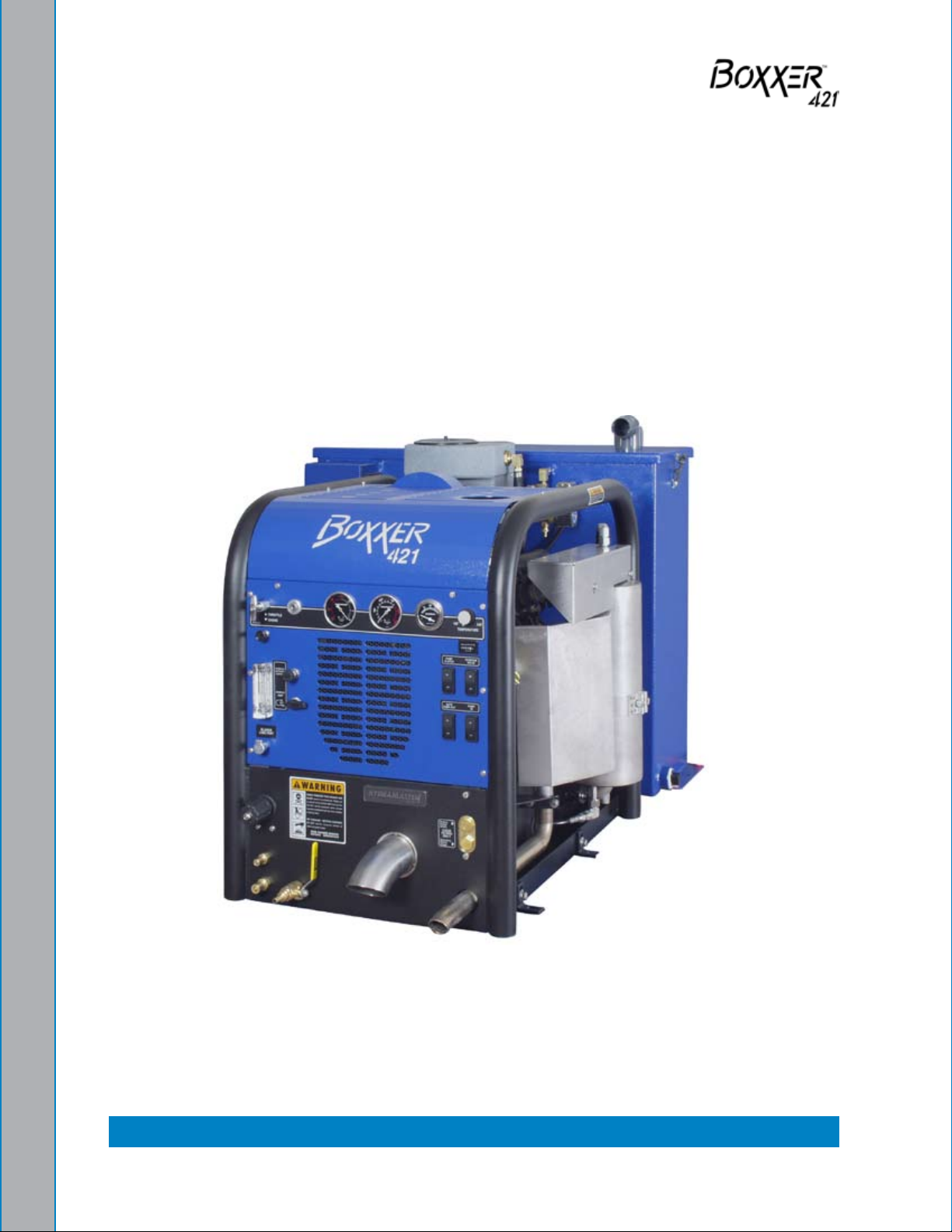
Figure 1-1. Boxxer 421 with Standard 70 Gallon Recovery Tank ................................. 1-1
Figure 1-2. Hard Water Map of Mainland United States ............................................. 1-14
Figure 2-1. Roof Vent Positions .................................................................................... 2-1
Figure 2-2. Recommended Placement ......................................................................... 2-2
Figure 2-3. Installation Using Tie Down Washers ......................................................... 2-3
Figure 2-4. Install Fuel Pump, Outlet Side Up .............................................................. 2-4
Figure 2-5. Fuel Pump Must Be in Vertical Position ..................................................... 2-4
Figure 4-1. Dash Assembly - View 1 of 2 ..................................................................... 4-1
Figure 4-2. Dash Assembly - View 2 of 2 .................................................................... 4-2
Figure 4-3. Location of Chemical Metering
Control and Chemical Pump Selector Valve ............................................. 4-6
Figure 4-4. Location of Blower Lube Port ..................................................................... 4-9
Figure 5-1. Service the Valves ...................................................................................... 5-6
Figure 5-2. Recirculation Fitting...................................................................................5-11
Figure 6-1. Flow Diagram - View 1 of 3 ........................................................................ 6-6
Figure 6-2. Flow Diagram - View 2 of 3 ........................................................................ 6-7
Figure 6-3. Flow Diagram - View 3 of 3 ........................................................................ 6-8
Figure 7-1. Electrical Schematic ................................................................................... 7-2
Figure 7-2. Wiring Diagram - View 1 of 3 ..................................................................... 7-3
Figure 7-3. WiringDiagram - View 2 of 3 ...................................................................... 7-4
Figure 7-4. Wiring Diagram - View 3 of 3 ..................................................................... 7-5
Figure 9-1. Machine Assembly - View 1 of 5 ............................................................... 9-2
Figure 9-2. Machine Assembly - View 2 of 5 ............................................................... 9-3
Figure 9-3. Machine Assembly - View 3 of 5 ................................................................ 9-4
Figure 9-4. Machine Assembly - View 4 of 5 ............................................................... 9-5
Figure 9-5. Machine Assembly - View 5 of 5 ............................................................... 9-6
Figure 9-6. Frame Assembly - View 1 of 3 .................................................................. 9-8
Figure 9-7. Frame Assembly - View 2 of 3 ................................................................... 9-9
Figure 9-8. Frame Assembly - View 3 of 3 ................................................................. 9-10
Figure 9-9. Engine Assembly...................................................................................... 9-12
Boxxer 421 Owner’s Manual: iv
Page 7

Figure 9-10. Dash Assembly - View 1 of 2 ................................................................. 9-14
Figure 9-11. Dash Assembly View 2 of 2 .................................................................... 9-15
Figure 9-12. Electrical Control Panel Assembly ......................................................... 9-17
Figure 9-13. Blower Heat Exchanger Assembly ......................................................... 9-19
Figure 9-14. Water Box Assembly .............................................................................. 9-20
Figure 9-15. Pump Assembly ..................................................................................... 9-21
Figure 9-16. Chemical Pump Assembly ..................................................................... 9-22
Figure 9-17. Fuel Pump Assembly ............................................................................ 9-23
Figure 9-18. Blower Assembly .................................................................................... 9-24
Figure 9-19. Vacuum Relief Valve (Collector Box) Assembly ..................................... 9-26
Figure 9-20. Exhaust Assembly .................................................................................. 9-27
Figure 9-21. Diverter Valve Actuator Assembly .......................................................... 9-29
Figure 9-22. Hi PSI Manifold Assembly ...................................................................... 9-30
Figure 9-23. By-Pass Valve Assembly ........................................................................ 9-32
Figure 9-24. Briggs and Stratton Voltage Regulator Modication .............................. 9-33
Figure 9-25. 70 Gallon Universal Recovery Tank Assembly ....................................... 9-34
Figure 9-26. 70 Gallon Universal Recovery Tank Cover Assembly ............................ 9-36
Figure 9-27. 100 Gallon Universal Recovery Tank Assembly ..................................... 9-37
Figure 9-28. 100 Gallon Universal Recovery Tank Cover Assembly .......................... 9-39
Figure 9-29. 70 Gallon Universal Recovery Tank
for 85 Rotomolded Tank Assembly ........................................................ 9-40
Figure 9-30. 85 Gallon Rotomolded Tank Assembly - View 1 of 2 ............................. 9-42
Figure 9-31. 85 Gallon Rotomolded Tank Assembly - View 2 of 2 ............................. 9-43
Figure 9-32. 85 Rotomolded Tank Assembly with Boxxer 421 ................................... 9-45
Figure 9-33. Chemical Jug Tray Assembly ................................................................. 9-47
v: Boxxer 421 Owner’s Manual
Page 8

Boxxer 421 Owner’s Manual: vi
Page 9
- General Information1
The Boxxer 421 is a compact, yet powerful truckmount carpet cleaning system which
can also be used for hard-oor cleaning and pressure washing. This high performance
machine features a 21 Hp Briggs and Stratton engine and the dual oil bath Tuthill Dominator
4005 Tri-lobe Blower, which provides low noise, low vibration operation. The advanced
heat exchanger system utilizes two separate exhaust heat exchangers for capturing “free
heat”.
The Boxxer 421 comes standard with a 70 gallon recovery tank (shown in Figure 1-1), a
5 gallon chemical jug, 100 ft vacuum and solution hoses and a 10 ft whip hose.
Figure 1-1. Boxxer 421 with Standard 70 Gallon Recovery Tank
Options include:
a 100 gallon recovery tank•
an Automatic Pump Out (APO) system•
a Thru Floor Exhaust Kit•
an 85 gallon fresh water tank•
1-1: General Information
Page 10

SYSTEM CONCEPT
The Boxxer 421 truckmount carpet cleaning system has many functions to perform
simultaneously.
The engine has to run at a consistent rpm. •
The vacuum has to pull air and dirty water back from cleaning site. •
The water pump provides stable pressure at proper water ow for cleaning. •
The chemical has to be injected into the water stream at the right concentration.•
The heating system must maintain proper heat. •
The recovery ta• nk must store dirty water until drained.
This is how the Boxxer 421 integrates all the functions:
Water is fed into the machine under tap pressure and it ows through the water conditioner
to the water box. (The water conditioner is offered as an option.) The solution is then
picked up by the high pressure pump and pressurized to the desired level. The water then
splits ow, as demanded by the technician.
The majority of the water ows to the by-pass valve assembly, then back to the water box.
The water ows from the water pump through the blower exhaust heat exchanger then
through the engine exhaust heat exchanger and out to the cleaning tool.
When the cleaning solution reaches a preset high temperature, it is released from the
system and directed to the recovery tank. Then cool water enters the system to regulate
the temperature. The engine exhaust diverter bypasses the heat from the exhaust heat
exchanger and simultaneously releases water from the system and directs it to the
recovery tank.
As there is no guess work in the manufacture of these highly advanced cleaning machines,
there must be none in preparing it to get the job done in the eld. It is the purpose of this
manual to help you properly understand, maintain and service your cleaning plant.
The manual contains installation and operation instructions as well as information required
for proper maintenance, adjustment and repair of Boxxer 421. Component troubleshooting
charts have also been included for your convenience. Follow the directions carefully and
you will be rewarded with years of protable, trouble-free operation.
It is imperative that no section be overlooked when preparing for operation of this
equipment.
This section of the manual contains the following information:
Contact Information
Warnings, Cautions and Notices
Responsibilities
Machine Specications
High Altitude Operation
Local Water Precautions
General Information: 1-2
Page 11

CONTACT INFORMATION
If you have any questions regarding the operation, maintenance or repair of this machine,
please contact your local distributor.
To nd a local distributor, please visit our website at
http://hydramaster.com/HowToBuy/DealerLocator.aspx
If your question cannot be resolved by your distributor or by the information within
the Owner’s Manual, you may contact HydraMaster direct using the following phone
numbers.
HOURS TELEPHONE NUMBERS E-MAIL ADDRESSES
Monday-Friday
Technical Support
(425) 775-7275
FAX : (800) 426-4225
techsupport@hydramaster.com
Technical Support
7:00 a.m. to 5:00 p.m.
Pacic Standard Time
Customer Service/Parts
(425) 775-7276
FAX: (425) 771-7156
Customer Service/Parts
parts@hydramaster.com
When calling your distributor, be sure to reference the serial number and date of
purchase.
FOR YOUR REFERENCE:
Serial No.____________________________________________________
Date of Purchase:_____________________________________________
Purchased From (Distributor): __________________________________
1-3: General Information
Page 12

WARNINGS, CAUTIONS AND NOTICES
HydraMaster uses this WARNING symbol throughout the manual to warn of
possible injury or death.
This CAUTION symbol is used to warn of possible equipment damage.
This NOTICE symbol indicates that federal or state regulatory laws may apply,
and also emphasizes supplemental information.
General Information: 1-4
Page 13

Warnings and Cautions specic to the Boxxer 421 include the following:
ENGINE COOLING: Units employing internal combustion engines must not be
enclosed within a van with doors and windows closed. Excessive temperatures
within the engine will result in premature engine failure and a compromise of
applicable warranty.
MOVING PARTS: Never touch any part of the machine that is in motion. Severe
bodily injury may result.
HOT SURFACES: During the operation of this equipment, many surfaces on the
machine will become very hot. When near the van for any reason care must be
taken not to touch any hot surface, such as heater, engine, exhaust, etc.
HEARING PROTECTION: The Occupational Safety and Health Administration
(OSHA) recommends the use of hearing protection when a technician is exposed
to an average of 85 decibels (this is an average of exposure over an 8 hour
period). This equipment can produce 85 decibels to a distance of 10 feet. Please
check with your local state agencies to see if OSHA standards apply to your
application.
NO SMOKING: It is unsafe to smoke in or around the vehicle.
CARBON MONOXIDE: This unit generates toxic fumes. Position the vehicle so
that the fumes will be directed away from the job site. Do not park where exhaust
fumes can enter a building through open doors, windows, air conditioning units
or kitchen fans.
TOXIC FUMES: Do not occupy the vehicle when the cleaning equipment is
operating. Toxic fumes may accumulate inside a stationary vehicle.
1-5: General Information
Page 14

ENGINE EXHAUST: The engine exhaust from this product contains chemicals
known to the State of California to cause cancer, birth defects or other reproductive
harm.
PORTABLE GAS TANK: Never operate this machine with a portable gas can
inside the truck. Doing so increases the risk of a re or explosion.
TRANSPORTATION OF FUEL CONTAINERS: Transportation in a vehicle of any
vented fuel container that presently has or has ever contained a ammable liquid
is strictly forbidden by HydraMaster and by federal and state regulation.
THROUGH-FLOOR DRILLING: Be cautious when drilling holes through the van
oor. Many vans have critical components mounted directly below the van oor
that could be damaged by a misplaced drill bit.
LEVEL OPERATION: During operation, van or trailer must be parked on level
ground not to exceed + or - 10 degrees. Failure to insure proper leveling may
prevent proper internal lubrication of engine, vacuum and/or high pressure
components.
The machine cannot be run in the IDLE position for cleaning upholstery, carpet or
ood extraction. This will void the warranty.
ACID RINSE AGENTS: The increased demand for “clear water” rinsing results
in the need for special care when using these acid based chemicals in your
equipment. The negative side of these products is the corrosive effects the acid
can have on metals, including swivels, pumps, heat exchangers, etc.
General Information: 1-6
Page 15

HydraMaster’s ClearWater Rinse has been formulated to protect vital components.
HydraMaster will not warranty parts that have been damaged from using
unprotected acid products that have obviously caused failures.
HARD WATER PROTECTION: Failure to take appropriate measures to prevent
scale build up can result in system failure and loss of warranty on affected
parts. Test the water in your immediate and surrounding areas with hard water
test strips. Assume all water obtained from wells is hard. If you are operating
in a “Hard Water Area” (3.0 grains or more per gallon), use a water softening
system.
FREEZE PROTECTION: There is often little warning before a cold spell. Therefore,
not protecting this equipment from freezing will result in costly downtime. Placing
an electric heater in the truck or parking the truck indoors will help to insure
against freezing, but should not be the primary method of freeze protection.
EXHAUST SYSTEM: Do not allow ammable material (i.e. oil, fuel, plastic or
wood products) to come in contact with the exhaust system.
The use of some chemicals through your mobile carpet cleaning plant can
seriously damage the internal plumbing, high-pressure pump, chemical pump
and heat exchangers. These harmful chemicals include concentrated acid (see
the pH chart at the end of this section), solvents (including d-Limonene), and
some paint, oil and grease removers with a high concentration of solvents.
1-7: General Information
Page 16
RESPONSIBILITIES
Purchaser’s Responsibilities
Prior to purchasing a van, ensure that the payload is suitable for all of the equipment •
that will be installed and transported. This includes and is not limited to: the truckmount,
recovery tanks, fresh water tanks, on-board water, hose reels, hoses, cleaning tools,
chemicals and drying equipment. Payload capacity information is available through
the auto dealer, the manufacturer’s web site, and is also located on the door pillar of
the driver’s side door.
Purchase a 42 - 60 Amp hour battery and have the battery ‘slow’ charge if it is new. •
The battery is normally available from the installation dealer.
If the battery is not fully charged, damage can occur to the engine charging
regulator.
Prior to dropping your van off at the distributor for the truckmount to be installed, have •
a spray-on bed liner applied to the oor such as Rhino Lining® or Line-X®.
Plywood and carpet are not recommended.
Prior to operating the truckmount, read this manual in its entirety and familiarize •
yourself with the information contained here. Special attention should be paid to all
Warnings and Cautions.
The distributor is responsible for the correct installation of the truckmount. The •
distributor is also responsible to train you in the correct and proper operation and
maintenance of the truckmount.
Any modication of the truckmount may void the warranty.
General Information: 1-8
Page 17

Distributor’s Responsibility
Acceptance of Shipment
Before accepting the truckmount, check the following
The truckmount should be free from any damage during shipping. Do not sign the 1.
delivery receipt until you have closely inspected the truckmount and noted any
damage on the delivery receipt. Hidden damage may be present even if the box looks
okay. It is recommended that the box be opened before you sign for the shipment.
Check the packing list and verify that all items are accounted for.2.
Installation Responsibilities
Ensure proper payload capacity. It is the distributor’s responsibility to verify that the •
equipment package does not exceed the vehicle capacity.
Ensure installation of a safe fuel tap system and through-oor ttings as provided by •
HydraMaster.
Ensure proper placement of the truckmount, recovery tank, fresh water tank, and •
accessories in the vehicle, and check that they are secured with bolts and back up
plates. The distributor should verify that the owner is in agreement with the layout.
Ensure proper connection of the fuel lines.•
Ensure proper connection and installation of the battery. Verify that the battery is in •
accordance with HydraMaster’s recommendation.
Check the pump, vacuum blower and engine oil levels prior to starting the •
truckmount.
Start and run the truckmount and check that all systems function properly.•
Test all hoses, wands and other accessories for correct operation.•
Ensure timely return of the document package.•
1-9: General Information
Page 18

Training
The distributor should provide a thorough review of the operation manual with the
purchaser along with instruction and familiarization in
How all the truckmount’s systems function.•
All safety precautions and their importance.•
How to correctly start and shut down the truckmount.•
How to correctly clean with the truckmount.•
Where and how often to check and change component oil levels.•
Freezing damage and how to avoid it. This includes explaining proper freeze guarding •
procedures.
How to do basic troubleshooting of the truckmount.•
Hard water damage and how to avoid it. This includes how to determine if hard water •
exists in your area and the installation and use of water softening systems.
The truckmount’s warranty and warranty procedures.•
General Information: 1-10
Page 19
MACHINE SPECIFICATIONS
Frame 24”W x 32”H x 36”D
Steel with Baked-on Powder Coated
Finish
Weight 709 lbs.
Engine Vanguard 21 HP Briggs and Stratton
Pressurized Oil System Engine Oil:
5W-30 Synthetic
Spin-on Filter, Oil Cooler
Ignition Electric Keystart
Vacuum Blower Dominator 4005, Tuthill/M-D Tri-Lobe, Blower Oil:
Pneulube
Pump HydraPump II, 3.5 gpm Hot Seals,
2,500 psi
Pump Oil:
15W-50 Synthetic
Chemical System Last-Step Chemical
Operating Pressure Up to 1,000 psi
Heating System 1 Stainless Steel Engine Exhaust
Exchanger
1 Coil and Fin Blower Exhaust Heat
Exchanger
Instruments Water Pressure Gauge, Liquid Filled,
0 - 1,500 psi
Hour Meter, Machine Runtime
Keyed Ignition, Start/Stop
Chemical Flowmeter, Clear Acrylic,
0 - 10 gph
Vacuum Gauge
Temperature Gauge
Recovery Tank 70 Gallon Aluminum, Powder Coated
Finish
Cleaning Wand Stainless Steel ‘S’-bend
Replaceable Grip
Rebuildable Solution Valve
1-11: General Information
Page 20
High Pressure
Solution Hose
100 ft , 1/4” High Temperature Lined/
Vinyl Covered
Hose Rated to 2,250 psi
Vacuum Hose 100 ft, 2” Reinforced Hose,
10 ft, 1 1-2” Reinforced Wand Whip Line
Standard Equipment Chemical Jug
Battery Box
Van Decal Package
Van Installation Kit
Owner’s Manual (on CD)
Owner’s Guide (paper)
HydraMaster Jacket
General Information: 1-12
Page 21

HIGH ALTITUDE OPERATION
Elevation plays a key role in how the truckmount will operate. Operation at high altitude
(above 5,000 ft) may require a high-altitude carburetor jet. Use of this jet at high altitude
will improve power, reduce fuel consumption and help reduce excessive carbon build-up
in the exhaust and heat exchanger systems.
Contact the local Briggs and Stratton dealer or HydraMaster to obtain the proper jet
size. Find your local Briggs and Stratton dealer at
http://vanguardengines.via.infonow.net/locator.
LOCAL WATER PRECAUTIONS
The quality of water varies greatly. Many areas have an excess of minerals in the water
which results in what is commonly called “hard water.” These minerals tend to adhere to
the insides of heater coils and other parts of the machines causing damage and a loss of
cleaning effectiveness. This inuences the reliability and efciency of equipment in direct
proportion to the level of hardness.
Hard Water Advisory
HydraMaster recognizes that any hard water deposits which might occur within the water
system of our truckmounts is a serious problem. The precision technology of truckmount
heat exchanger systems is intolerant of any foreign material. Hard water deposits will
ultimately decrease the performance of the system and are expected to seriously lower
the reliability of the machine.
To validate a machine’s warranty, HydraMaster requires that all machines operating in
designated “Hard Water Areas” (3.0 grains or more per gallon) be tted with a water
softening system, or a properly installed magnetic-type descaler must be used and
maintained. Periodic descaling or acid-rinsing alone is not adequate in these areas.
HydraMaster does not recommend any particular type or brand; however, the relative
effectiveness of some types of magnetic descalers or softeners may require additional
periodic use of descaling agents.
HydraMaster also recommends, in the strongest possible terms, that machines in all areas
be tted with a water softening system for improved operation and reliability.
Failure to take appropriate measures to prevent scale build up can result in
system failure and loss of warranty on affected parts.
1-13: General Information
Page 22

Hard Water Area Map
The hard water map, shown in Figure 1-2, denes hard water areas in the continental
United States which compromise uid related components such as hoses, ttings, heaters,
pumps, valves and water-cooled engines. For other countries, hard water area maps can
be obtained from geological societies.
Hard Water Map of Mainland United StatesFigure 1-2.
The map shown in Figure 1-2 is provided for general reference only. Water
hardness in your geographical location should be conrmed by testing.
General Information: 1-14
Page 23

Water Softener
Cleaning efciency and equipment life is increased, chemical use decreased, and the
appearance of cleaned carpets enhanced when water softeners are incorporated in
hard water areas. HydraMaster strongly urges the use of water softener units with the
Boxxer 421 in areas exceeding 3.0 grains per gallon.
Failure to use a water softener in these areas will invalidate the machine’s warranty.
Referring to the hard water area map shown Figure 1-2, determine the quality of water
in your area and take immediate action if the water hardness exceeds 3.0 grains per
gallon.
The relatively low cost of a water softener service is more than made up for by an increased
life of machine parts, reduced chemical costs and continued cleaning efciency. The
water softener will also increase the effectiveness of the cleaning chemicals, therefore
less chemical will be needed.
Contact a water softener distributor in your area for information on the rental of a simple
water treatment unit to carry in your truck. Be sure to charge the water softener in
accordance with the capability of the softener.
For example: If the softener will treat 900 gallons of water and the machine uses an
average of 30 gallons/hour, for an average of 5 hours a day, this equals 150 gallons per
day. In 6 days the machine would use 900 gallons of water. Therefore, the softener would
need to be charged every 6 working days for maximum softening.
1-15: General Information
Page 24

Waste Water Disposal Advisory
There are laws in most communities prohibiting the dumping of recovered “gray” water
from carpet cleaning in any place but a sanitary treatment system.
The cleaning rinse water, recovered into your unit’s vacuum recovery tank, contains
materials such as detergents, and must be safely processed before entering streams,
rivers and reservoirs.
In most cases, an acceptable method of waste water disposal is to discharge into a
municipal sewage treatment system after rst ltering out solid material such as carpet
ber. Access to the sanitary system can be obtained through a toilet, laundry drain, RV
dump, etc. Permission should rst be obtained from any concerned party or agency.
One disposal method which usually complies with the law is to accumulate the waste
water and haul it to an appropriate dump site. Another solution to the disposal problem
is to equip your Boxxer 421 with an Automatic Pump-Out System (APO). These systems
are designed to remove waste water from the extractor’s recovery system and actively
pump the water through hoses to a suitable disposal drain.
HydraMaster makes an APO System which can be ordered with new equipment or
installed later.
When properly congured, the systems will continuously monitor the level of waste water
and pump it out simultaneously with the cleaning operation. The hidden benet of this
process is that the technician does not have to stop his/her cleaning to empty the recovery
tank.
IN ACCORDANCE WITH EPA, STATE AND LOCAL LAWS, DO NOT DISPOSE OF
WASTE WATER INTO GUTTERS, STORM DRAINS, STREAMS, RESERVOIRS,
ETC.
The penalties for non-compliance can be serious. Always check local laws and
regulations to be sure you are in compliance.
General Information: 1-16
Page 25
2- Installation Information
When selecting a truck, remember the preferable vehicle for a Boxxer 421 installation is a
cargo van with a heavy-duty suspension package and a half ton capacity. If a fresh water
tank is added, a three quarter ton or larger capacity van, with a 2,400 lb. payload capacity,
is required.
Be cautious when drilling any holes through the van oor. Many vans have critical
components mounted directly below the van oor that could be damaged by a
misplaced drill bit.
Truck Preparation
The manufacturer recommends the installation of a spray-on bed liner in the vehicle prior
to installation of machine.
This provides ‘metal to cushion’ mounting rather
than ‘metal to metal’ and makes for an attractive
van interior.
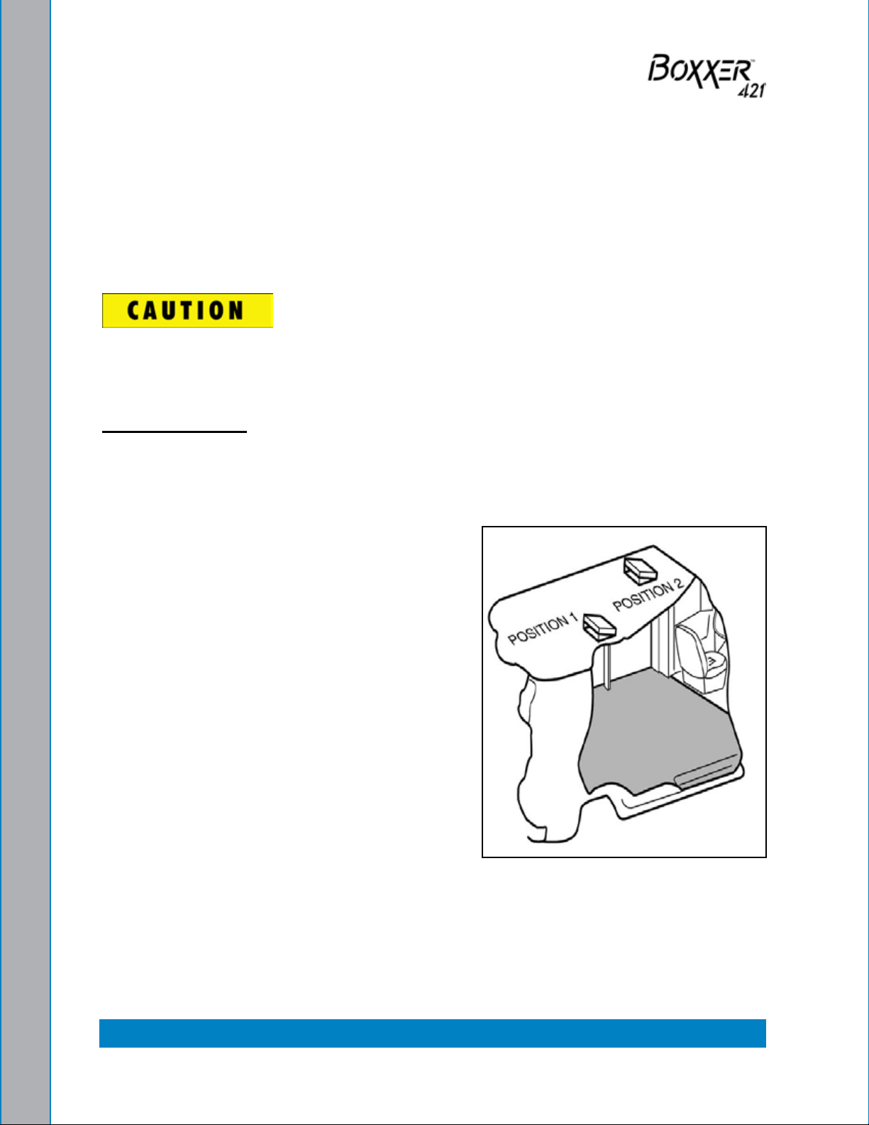
It is highly recommended that you have roof
vents installed in vehicles operated in hot
weather locations. Roof vent positions are shown
in Figure 2-1.
Roof Vent PositionsFigure 2-1.
2-1: Installation Information
Page 26
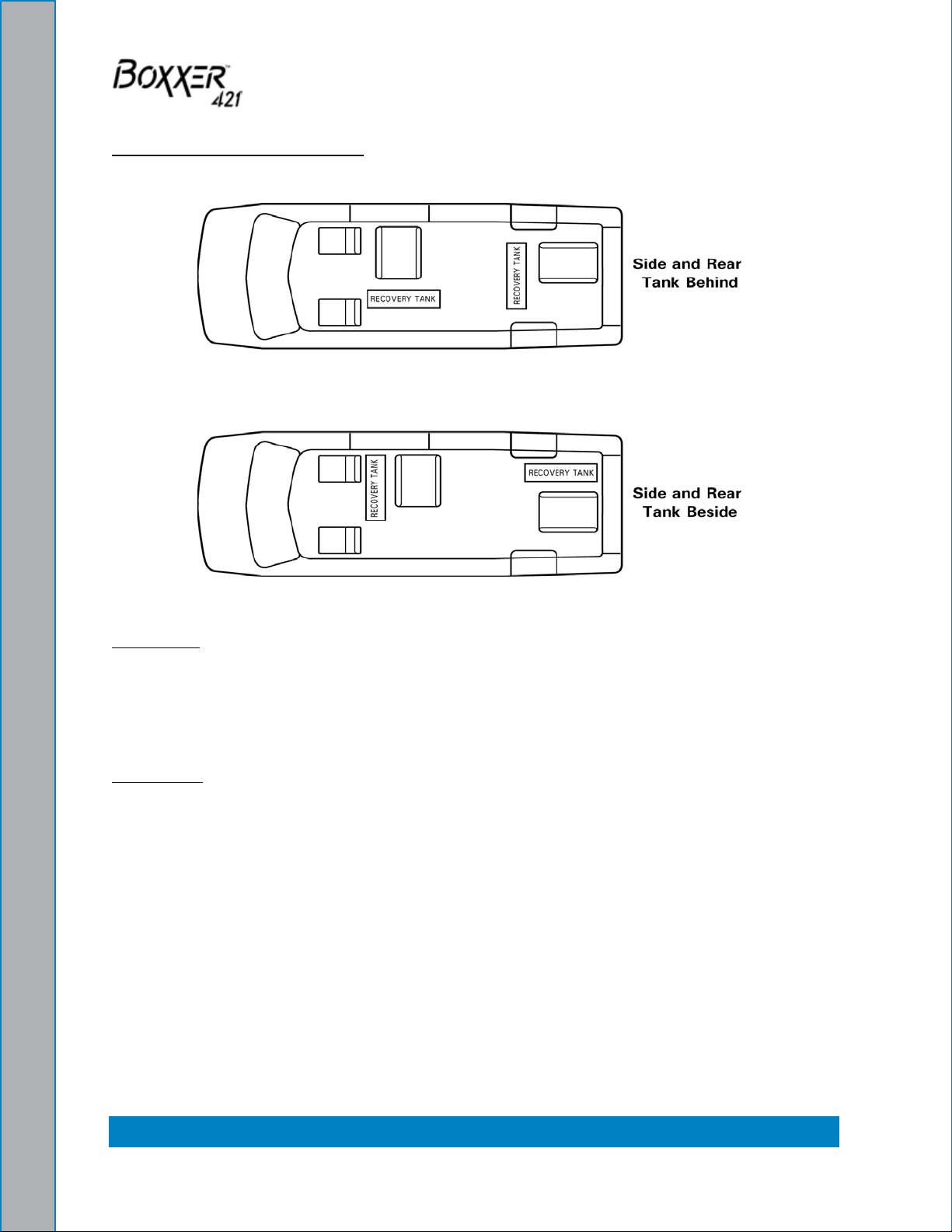
Placement Of Unit In Vehicle
There are two recommended unit placements (see Figure 2-2).
Recommended PlacementFigure 2-2.
Side Door
Most installations are side door. This provides rear access for accessories and hoses as
well as unobstructed access to the component/working side of the machine, thus making
it a bit easier to perform maintenance and/or repair without removing the unit from the
truck.
Rear Door
Although this location partly limits working access, it does direct the noise away from the
cleaning site. Some cleaners in the colder areas prefer this location because it puts the
weight over the rear wheels for better traction in ice and snow. Rear mounting requires
the unit to be slid to the right side as far as possible.
This not only provides adequate working space on the component side of the unit but also
improves weight distribution inside the van (engine and component weight line up over
drive shaft). Also, it is physically easier to load the unit into the rear door due to the height
of the van bed.
Installation Information: 2-2
Page 27
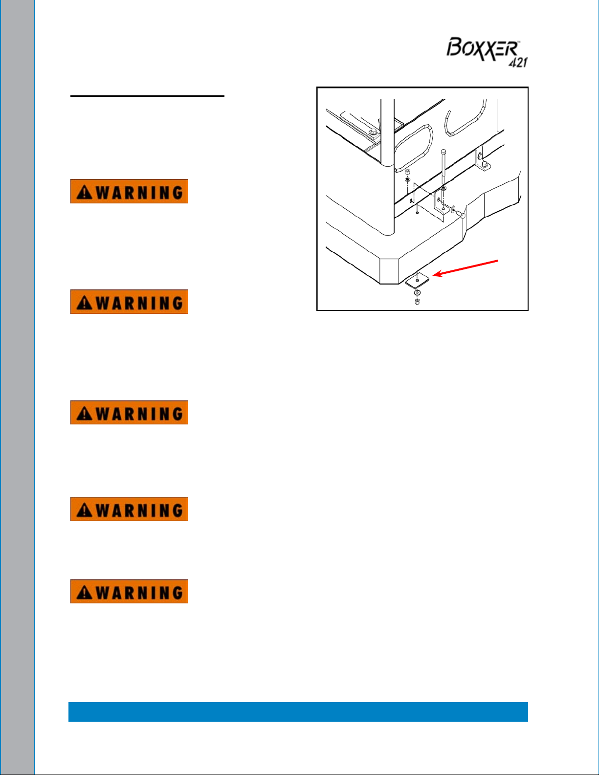
Machine Tie Down Washers
Secure the machine to the oor of the van
with the four tie down washers provided. This
safety measure will ensure that the machine
will not slide inside the van. See Figure 2-3
for the correct installation.
Ensure that the machine is well secured
to the oor of the van with the hardware
supplied. A sudden or crash stop will cause
the machine to rocket forward. Protect
yourself and the machine. SECURE IT!
It is recommended by the manufacturer
that the exhaust from the front of the
Tie Down Washers
Installation Using Figure 2-3.
machine be vented down under the truck
to prevent carbon monoxide from entering the job site. Always park the truck so
the exhaust is blowing away from the job site.
Never operate this machine with a portable gas can inside the truck. Doing so
increases the risk of a re or explosion.
Mount a re extinguisher just inside the rear or side door for emergencies.
Transportation in a vehicle of any vented fuel container that presently holds or
has ever held a ammable liquid is strictly forbidden by HydraMaster and by
federal and state regulation.
The engine exhaust from this product contains chemicals known to the State of
California to cause cancer, birth defects or other reproductive harm.
2-3: Installation Information
Page 28
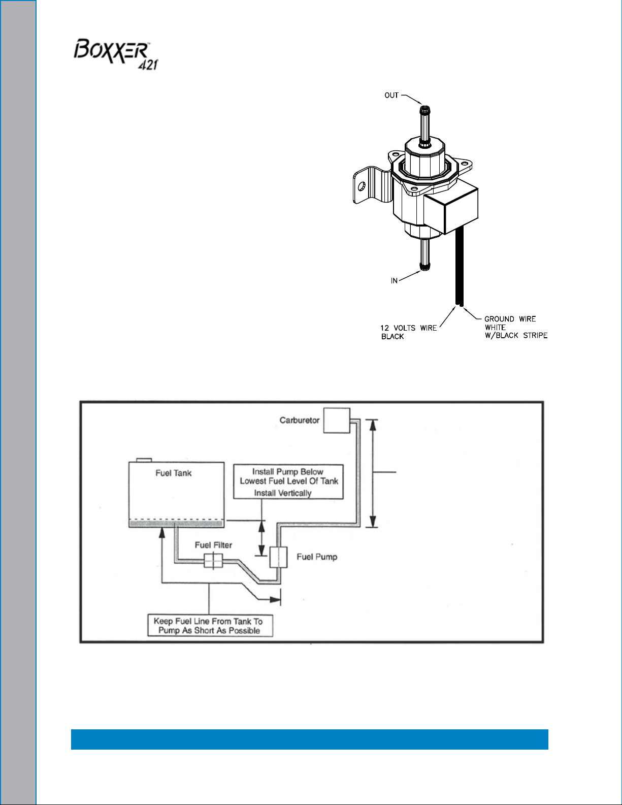
ORIENTATION OF FUEL PUMP
For proper fuel pump operation and fuel ow, the
vehicle’s fuel pump must be installed in a lower
position with respect to the fuel tank and in as
vertical a position as possible (outlet side up - see
Figure 2-4 and Figure 2-5).
Mount the fuel pump away from sources of heat.
Install Fuel Pump, Figure 2-4.
Outlet Side Up
Installation Information: 2-4
Pump Can Push Fuel
6.5 ft Vertically
Fuel Pump Must Be in Vertical PositionFigure 2-5.
Page 29

3 - Cleaning Information
The Boxxer 421 has been engineered using the latest and most sophisticated technology
available to produce the nest carpet cleaning results possible. Despite this, it remains
only a tool of the carpet cleaning trade and can produce only as a good a job as the
person operating it.
HydraMaster strongly recommends attending an Institute of Inspection, Cleaning and
Restoration Certication (IICRC) approved school as soon as possible and to always
follow the IICRC guidelines when cleaning carpets or hard surfaces.
This section describes the carpet cleaning procedure in the following areas:
Precautions
Preparing the Carpet for Extraction
Rinse and Recover
Overwetting
Streaking
Cleaning Tool Tips
3-1: Cleaning Information
Page 30

PRECAUTIONS
The use of some chemicals (such as concentrated acids and/or solvents) in your
truckmount can seriously damage the internal plumbing and high pressure pump.
HydraMaster strongly recommends purchasing a water softener system to prevent the
buildup of scale and hard water deposits in your truckmount.
HydraMaster recommends only the use of chemicals containing rust and corrosion
inhibitors and water softening agents to prevent chemical buildup which may lead to
component failure and warranty invalidation.
Increased demand for a neutralizing rinse results in the need for special care when using
these acid based chemicals in your truckmount The negative side of these products is the
corrosive effects the acid can have on metals, including ttings, pumps, heat exchangers,
etc.
HydraMaster’s ClearWater Rinse™ has been formulated to protect vital components.
HydraMaster will not warranty parts that have been damaged from using acid products
that have obviously caused failures.
PREPARING THE CARPET FOR EXTRACTION
Pre-vacuum the carpet
Whether you instruct the customer to pre-vacuum or you offer it as part of your service,
proper vacuuming will make your job easier with superior end results. The more time
spent removing loose particulate soil, the easier it will be to remove the oily soil stuck to
the bers.
Pretreat the carpet
This process of applying trafc lane type chemicals to the carpet (whether by sprayer or
rotary scrubber) is essential prior to extraction with your truckmount.
By applying cleaning agents to the carpet and letting them dwell 10-20 minutes prior to
rinsing, you allow the product to dissolve and emulsify the oily, sticky binders holding the
soil to the ber. This will allow more soil to be removed in one or two cleaning passes and
help prevent over-wetting.
Remember the solution coming out of your cleaning tool is only in contact with the carpet
ber for a few seconds. Relying on the rinse detergent to do the majority of the cleaning
will result in overly long dry times and excess detergent residue left in the carpet.
HydraMaster recommends the use of our pre-sprays: Fastbreak™ for residential carpet
and Blitz™ for commercial carpet needs.
Cleaning Information: 3-2
Page 31

RINSE AND RECOVER
Whether you are using a wand or an RX-20™, you should clean an area approximately
3 ft. x 3 ft. with the solution valve open then immediately go over that area with vacuum
only to remove any excess moisture.
Olen ber is becoming more popular, particularly in commercial installations. The process
mentioned above can leave excessive residual moisture because olen bers will not
absorb any of the cleaning solution. You must only apply solution during the backward
stroke of the wand so it can be immediately captured by the vacuum head. RX-20™
users should follow each pass with a dry pass. Failure to follow this procedure will cause
solution to ow to the back of the carpet along with some of the soil. This, along with any
soil imbedded in the backing, will be wicked to the surface of the bers as the carpet
dries.
HydraMaster recommends the following rinse aids: Alkaline - Hydra-Dri Powder™ or
Hydra-Clean™. Acid - ClearWater Rinse™.
OVERWETTING
Overwetting is an annoyance to all concerned. Extended drying times will leave the
customer with a negative impression of both the cleaning company and the process
used.
Several factors that will cause over-wetting include:
Too few vacuum strokes.1.
Clogged vacuum blower lter or vacuum recovery tank lid not sealing properly.2.
Vacuum recovery tank drain valve left partially open.3.
Obstructed, cut or kinked vacuum hoses.4.
Obstructed vacuum hoses while cleaning a heavily foam-saturated carpet (it is 5.
recommended to use a crystal type defoamer distributed evenly over the carpet).
STREAKING
Streaks in the carpet can appear in both clean or dirty areas and normally appear in
heavily soiled, light colored carpets.
Possible reasons of streaking may include:
Clogged or improperly angled spray nozzles.1.
Spray nozzles that overlap, concentrating the solution.2.
A partially clogged vacuum head.3.
Inconsistent solution temperature.4.
3-3: Cleaning Information
Page 32

CLEANING TOOL TIPS
Wands
With a wand, keep cleaning strokes short, front to back, and run a “dry pass”.
After pulling the wand for a strip of 3 or 4 ft long with the solution trigger activated, go back
up to the top of the stroke, and make a “dry “ pass [i.e. no solution owing]. This gives the
wand a second chance to pick up the solution on the carpet.
If you do not run a dry pass, the carpet can take longer to dry, and, possibly, the pad under
the carpet can become saturated.
Be aware of the carpet seams; try to use strokes that are parallel with the seam. Avoid
pulling the want across the seam. Every stroke can peel the seam connection and pull
the carpet off the oor.
Also, tilt the wand handle down [head up] to move the tool forward, and away from you,
on the carpet. This means less pull on the carpet and less work for you.
Cleaning Information: 3-4
Page 33

3-5: Cleaning Information
Page 34

Rotary Tool: RX-20
Rotary tools are easier to move on the carpet, but harder to control at rst. With a rotary
tool, remember to keep strokes short and side-to-side.
Before turning on the RX-20, adjust the handle; it should rest right below or even with the
bottom of your pants’ front pockets, with the tool resting at on the oor. Take your time
in adjusting the tool’s height; make sure the head of the tool is at with the oor while you
are holding the handle. Relax your posture; the more difcult it is to hold the tool’s head
at on the oor surface, the more quickly you will tire.
While the tool is running, control the left and right movements of the tool by tilting the head
to the front and back, and lifting the handles up and pushing the handles down. The tool
can be driven to the forward and backward by tilting the head of the unit to the left and
right. The head must be turning to use the self driving feature of the tool, and only requires
a slight bit of pressure to handles to get the head to move the tool across the oor.
As with the wand, drying times will be improved if you run a dry pass between wet passes.
Hold down the solution trigger and move the unit left or right across the oor 3 or 4 ft, then
immediately back across the same pass, without the solution owing, to make the dry
pass. Make the next pass half-overlapping the previous pass.
Use the RX-20 in very heavily trafcked areas or if it has been a long time since the carpet
has been cleaned. Beware of the seam edges of carpets and transition edges between
oor surfaces. Use extreme caution when cleaning these areas.
Sometimes it is necessary to use an edge tool or wand to run the perimeter of the room
on in difcult-to-reach areas where the circular head of the rotary units will not reach.
Cleaning Information: 3-6
Page 35

Upholstery Tool: DriMaster
Use the upholstery tool on small rugs and furniture. When you clean rugs, be sure that the
temperature and chemicals are safe for that particular type of rug.
As with the larger tools, do not leave the surface of the upholstery too wet. Adjust the
volume of water on the tool without it touching any surface: the water should just barely
come out of the tool before the vacuum pulls it back in. The water will only just spray the
top layer of the furniture and the vacuum will pull the dirty water back into the tool.
If you nd it necessary to do a dry pass, keep strokes short to limit the amount of water
that comes into contact with the fabric surface.
3-7: Cleaning Information
Page 36

Cleaning Information: 3-8
Page 37

4 - Operating Instructions
This section describes how to operate the Boxxer 421, starting with a description of the
dash assembly (see Figure 4-1).
Ignition Switch
Throttle
Choke
Automatic Pump-out Switch
Figure 4-1. Dash Assembly - View 1 of 2
The dash assembly controls the:
System’s power on/off and speed•
Pump clutch•
Diverter valve•
Automatic Pump-Out (APO) if included in the conguration•
Pump-In system if included in the conguration•
Pump Clutch
Switch
Diverter Valve
Switch
Pump-in Switch
4-1: Operating Instructions
Page 38

The dash assembly also includes the solution thermostat; the temperature, vacuum and
pressure gauges; and the hour meter (see Figure 4-2).
Vacuum Gauge
Pressure Gauge
Temperature Gauge
Thermostat
Hour Meter
Figure 4-2. Dash Assembly - View 2 of 2
EXHAUST DIVERTER SYSTEM
The exhaust diverter system consists of two components:
Diverter valve1.
Pump clutch.2.
The diverter valve directs the ow of the exhaust through the coil heat exchanger or
directly out of the machine via the diverter exhaust mufer.
The pump clutch allows the pump to be turned on and off through a switch. This will
enable the machine to be used for ood extraction without the need for an inlet garden
hose connected to the machine, thus preventing excessive lling of the recovery tank
through the temperature control system.
The Boxxer 421 can run in two different modes: cleaning or ood extraction mode.
Operating Instructions: 4-2
Page 39

Cleaning Mode
To run the machine in cleaning mode:
Turn the PUMP CLUTCH switch and DIVERTER VALVE switch to the “ON” 1.
position.
Adjust TEMPERATURE SELECTOR knob to the desired temperature.2.
Flood Extraction Mode
To run the machine in ood extraction mode:
Turn the PUMP CLUTCH switch and DIVERTER VALVE switch to the “OFF” 1.
position.
Drain the water box completely. 2.
When the machine is being run or after it has just been shut down, caution should
be used around the mufer and the exhaust diverter surfaces as they become hot
during operation. Failure to heed this warning may result in severe bodily injury.
Do not use excessive force when engaging and disengaging the heat exchanger
bypass lever. This may cause damage to the exhaust diverter.
In order for the diverter valve to operate properly, it should periodically be engaged and
disengaged.
4-3: Operating Instructions
Page 40

The diverter valve adjustment, explained in the following subsection, is to be
performed only by the distributor, not by the owner. Warranty may be voided if the
adjustment is made by anyone other than a certied distributor.
To nd a local distributor, please visit our website at http://www.hydramaster.com/
HowToBuy/DealerLocator.aspx.
Adjustment After Installation:
Machines that are equipped with a diverter valve may need adjustment after the machine
has been installed.
Prior to running the machine, perform the following steps:
Locate the actuator connected to the diverter valve arm which is located between 1.
the blower and engine exhaust heat exchanger.
The actuator shaft is connected to the diverter valve arm. 2.
Pull the actuator shaft forward and listen if the poppet 3.
seals against the seat in the diverter valve.
Push the actuator shaft back and listen if the poppet seals 4.
against the seat in the diverter valve.
If the poppet seats in both directions, the diverter a.
actuator is in proper adjustment.
If the poppet does not seat in one or both directions, b.
the valve is out of adjustment. Perform the following
steps to adjust the diverter actuator shaft.
The end of the actuator shaft is threaded into the diverter 5.
arm and is secured into position with a backup nut. This
nut must be loosened to allow adjustment.
Loosen the actuator backup nut. This will allow you to 6.
rotate the actuator shaft clockwise or counterclockwise.
Rotate the actuator shaft one half turn at a time. Then pull
the actuator shaft forward and back. Listen to hear if the
poppet seals in the seat of the diverter valve. Repeat this
step until the diverter poppet seals in both directions.
Apply red Loctite on the thread of the actuator shaft. 7.
Retighten the backup nut.
Recheck the adjustment. Move the actuator shaft forward 8.
and back. If the diverter poppet seals in both directions,
the diverter is now properly adjusted.
Operating Instructions: 4-4
Page 41

START UP
Perform daily and periodic maintenance as specied in this Owner’s Manual. 1.
Connect all required hoses, including a garden hose for water supply. 2.
Connect the cleaning tool to the length of hose required to perform the cleaning.3.
The machine cannot be run in the “IDLE” position for cleaning upholstery, carpet
or ood extraction. This will void the warranty.
In order to achieve consistent adjustable temperatures, an operating pressure of
200 psi must be maintained.
4-5: Operating Instructions
Page 42

CARPET OR HARD SURFACE CLEANING
Start the engine with throttle switch in 1.
“IDLE” position.
Allow machine to run in idle for 2 - 3 2.
minutes to warm up.
Connect hoses.3.
Connect wand or tool.4.
Set THROTTLE to “HIGH”.5.
If used, turn PUMP IN switch to “ON”.6.
Turn PUMP CLUTCH switch to “ON”.7.
Turn DIVERTER switch to “ON”.8.
Set temperature to desired level.9.
If used, turn the AUTOMATIC PUMP-10.
OUT switch to “ON”.
Set cleaning pressure at desired level. 11.
Suggested settings
Carpet Cleaning: 300 – 400 psi; a.
Hard Surface: 1,000 psi or as b.
indicated on the tool.
Turn the CHEMICAL PUMP SELECTOR VALVE to the “PRIME” position to purge 12.
any air from the system (seeFigure 4-3).
With the machine running at operating speed, block off the vacuum intake to a.
the recovery tank. The vacuum gauge should read between 12” Hg and 14” Hg.
This will assist in priming the chemical system.
When the chemical begins to ow through the ow meter, with the ow indicator b.
reading maximum ow for at least 30 seconds, turn the CHEMICAL PUMP
SELECTOR valve to “ON”. The restriction can now be removed from the vacuum
inlet.
Then, while spraying solution from the cleaning tool, adjust the chemical ow by c.
turning the CHEMICAL METERING CONTROL knob as necessary.
Commence cleaning.13.
Chemical
Metering
Control
Chemical Pump
Selector Valve
Figure 4-3. Location of Chemical
Metering Control and Chemical Pump
Selector Valve
Operating Instructions: 4-6
Page 43

UPHOLSTERY CLEANING
Start engine with the THROTTLE switch in “IDLE” position. 1.
Allow the machine to run in idle for 2 - 3 minutes to warm up.2.
Connect the hoses. 3.
Connect the upholstery tool.4.
Set the THROTTLE to “HIGH”.5.
If used, turn the PUMP-IN switch to “ON”.6.
Turn the PUMP CLUTCH switch to “ON”.7.
Turn the DIVERTER VALVE switch to “ON”. 8.
During upholstery cleaning if you desire a lower temperature you may want to 9.
leave the DIVERTER VALVE switch in the “OFF” position. The engine exhaust heat
exchanger is bypassed; the heat will be obtained from the engine coolant and blower
exhaust heat exchangers.
Set the temperature to the desired level.a.
If used, turn the AUTOMATIC PUMP-OUT switch to “ON”.b.
Set the cleaning pressure at the desired level (300 – 400 psi).10.
Turn the CHEMICAL SELECTOR PUMP VALVE to the “PRIME” position to purge 11.
any air from the system.
When the chemical begins to ow through the ow meter, with the ow indicator a.
reading maximum ow and the PRIME line pulsing, turn the CHEMICAL
SELECTOR PUMP VALVE to “ON”.
Then, while spraying solution from the cleaning tool, adjust the chemical ow by b.
turning the CHEMICAL METERING CONTROL knob as necessary.
Commence cleaning.12.
4-7: Operating Instructions
Page 44

FLOOD EXTRACTION
Start the engine with the THROTTLE cable in “IDLE” position. Allow the machine to 1.
run in idle for 2 - 3 minutes to warm up.
Connect hoses.2.
Connect wand or tool.3.
Set the THROTTLE to “HIGH”.4.
If used, turn the AUTOMATIC PUMP-OUT switch to “ON”.5.
Commence water extraction.6.
Make sure the PUMP CLUTCH and DIVERTER VALVE switches are in the “OFF”
position.
Operating Instructions: 4-8
Page 45

SHUT DOWN
Flush clear water through the chemical system for 10 seconds. Turn off the chemical 1.
ow meter.
Cool the machine by lowering the adjustable thermostat to the “LOW” position and 2.
the DIVERTER CONTROL switch to the “OFF” position. Spray the cleaning wand
into the vacuum hose for 3 - 5 minutes. The chemical should now be ushed from
the truckmount, hoses and cleaning tool.
If the machine is not properly cooled, the water box can overow.
Remove the vacuum hose.3.
Lubricate the blower to prevent it from 4.
rusting internally.
Allow the unit to run for a few minutes a.
with the vacuum hose disconnected
in order to remove moisture from the
blower.
Cap off the inlet(s) to the vacuum tank.b.
Spray a HydraMaster-recommended c.
Blower Lube
Port
spray lubricant into the “BLOWER LUBE
PORT” for about 5 to 10 seconds while
the unit is running (see Figure 4-4).
Uncap the inlet(s) and run the unit for d.
another minute to allow the blower to
cool down.
Figure 4-4. Location of Blower
Lube Port
If freeze guarding is necessary, perform the 5.
freeze guard procedure at this time (see Section TBD for Freeze Guarding).
Lower the engine rpm to idle.6.
Turn the ignition switch to “OFF.”7.
Drain the water box.8.
Drain the vacuum tank. The vacuum lter should be cleaned prior to mobilization of 9.
the van.
In accordance with the EPA, state and local laws, do not dispose of waste water
into gutters, storm drains, streams, reservoirs, etc.
Perform daily maintenance as specied in Section 10. 5 of this Owner’s Manual.
4-9: Operating Instructions
Page 46

Operating Instructions: 4-10
Page 47

5 - Machine Maintenance
To avoid costly repairs and downtime, it is imperative to develop and practice good
maintenance procedures. These procedures fall into daily, weekly, monthly and quarterly
increments and are outlined below. All maintenance must be performed by qualied
service personnel.
A maintenance log, provided in the Owner’s Guide, must be correctly and completely lled
out. HydraMaster may request to inspect the logs before a warranty claim is honored.
It is recommended that the log be afxed to the vehicle door near the truckmount for
convenience and to serve as a maintenance reminder.
This section describes how to properly maintain the truckmount in the following areas:
Operational Maintenance
Overall Machine Maintenance
High Pressure Pump Maintenance
Vacuum System Maintenance
Descaling Procedure (Required)
Freeze Guarding
5-1: Machine Maintenance
Page 48

OPERATIONAL MAINTENANCE
Daily:
Check engine oil level. •
Check high pressure pump oil. Add as necessary. •
Inspect garden hose screen. Clean as needed. •
Visually inspect machine for loose wires, oil leaks, water leaks, etc. •
Lubricate the blower with a HydraMaster-recommended lubricant.•
Weekly:
Inspect vacuum recovery tank S/S lter. •
One time change of oil and oil lter after rst 5-8 hours of use.•
Check oil level in blower. •
Check drive system screws. Tighten as needed. •
Check pump drive belt for wear. •
Check pump pulleys. •
Check high pressure water lines for wear or chang. •
Check all nuts and bolts. Tighten as needed. •
Inspect vacuum relief valve. Clean and lubricate as necessary. •
Clean vacuum recovery tank thoroughly with high pressure washer. •
Check wiring for chang. •
Flush water and chemical system with 50/50 white vinegar solution. .•
Monthly
Change engine oil and oil lter (every 50 hrs). •
Change blower oil (every 50 hrs).•
Check engine air cleaner lter. Clean as necessary. •
Check water level in battery. Clean connections as needed.•
Quarterly
Check fuel lines. •
Clean and gap spark plugs. •
Check drive coupler for cracks or wear. Replace as necessary. •
Change pump oil. •
500 Hours
Replace plugs in the drive coupling, between the engine and the blower. •
Machine Maintenance: 5-2
Page 49

OVERALL MACHINE MAINTENANCE
Maintaining the original appearance of your unit is important for two reasons:
It represents a big dollar investment for your cleaning business and its appearance 1.
should reect that fact. A dirty machine is not professional.
Maintenance, troubleshooting, and repair is much easier to accomplish on a clean, 2.
well maintained unit. Regular cleaning of the machine offers you an opportunity to
visually inspect all facets of the machine and spot potential problems before they
occur.
The following maintenance is recommended by the manufacturer at the frequency
indicated.
After Each Job
Check recovery tank and the lter basket.•
Daily
Wipe machine down thoroughly with a damp cloth.•
Flush recovery tank out thoroughly.•
Remove, thoroughly clean and re-install S/S lter and blower lter screen in recovery •
tank. Grease threads.
Inspect and clean vacuum slot on cleaning wand.•
Check wand head for sharp edges that could tear carpet. File down as needed.•
Clean wand to maintain original appearance.•
Wipe down vacuum and high pressure hoses as needed.•
Visually inspect hoses for cuts, etc.•
5-3: Machine Maintenance
Page 50

Weekly
Wipe down entire unit as needed.•
Apply good coat of auto wax to all painted surfaces inside and out, and to control •
panel.
Thoroughly clean recovery tank using high pressure hot water (unit with optional high •
pressure cleaning gun may be used for this).
Remove at lter in recovery tank and thoroughly clean, removing all lint build-up. •
Inspect for damage and re-install.
Empty chemical from chemical container. Wash out thoroughly to remove any chemical •
build-up.
Inspect chemical feed line strainer and use 50% white vinegar/water solution to remove •
any chemical build-up.
Thoroughly clean wand and inspect for clogged jet, debris in vacuum slot and leaking •
ttings at valve.
Apply light coat of auto wax to wand.•
Thoroughly clean vacuum and high pressure hoses including hose cuffs.•
Inspect for wear or damage to hoses and quick connect ttings.•
Inspect garden hose connect/adapter screen for debris. Remove and clean •
thoroughly.
Inspect all lines for wear or abrasions that may cause possible leaks.•
Machine Maintenance: 5-4
Page 51

HIGH PRESSURE PUMP
Daily
Check the oil level and the condition of the oil. The oil level should be up to the center of
the sight glass on the back of the pump.
If the oil becomes discolored and contaminated, one of the oil seals may be
damaged. Refer to the Service Section.
Do not operate the pump if the crankcase has been contaminated with water.
Do not leave contaminated oil in the pump housing or leave the housing empty.
Remove contaminated oil as soon as it is discovered and replace it with clean oil.
Periodically
Change the oil after the rst 50 hours of operation, and every 500 operating hours
thereafter. When changing, remove the drain plug on the oil drain center located on the
frame so all oil and accumulated sediment will drain out.
Do not turn the drive shaft while the oil reservoir is empty.
Protect the pump from freezing.
The next few pages explain how to disassemble and inspect all easily serviceable parts
of the pump.
5-5: Machine Maintenance
Page 52

Do not disassemble the hydraulic end unless you are a skilled mechanic. For
assistance, contact the distributor in your area.
Servicing the Valves (See Figure 5-1)
Remove the hex valve plugs: 1.
Top — discharge
Bottom — inlet
Machine Maintenance: 5-6
Figure 5-1. Service the Valves
Page 53

Unthread the valve plug and examine the O-ring under the plug for cuts or distortion. 2.
Replace it if it is worn. Lubricate new O-rings before installing.
Grasp the valve retainer by the tab at the top with needle-nose pliers, then remove 3.
the O-ring at the bottom of the valve chamber.
Inspect all valve parts for pitting, gouges, or wear. If wear is excessive, replace valve 4.
assembly.
Re-install valve assemblies:5.
Using a clean towel, clean the valve chamber.a.
Install the O-ring into the high pressure manifold.b.
Install the valve assemblies into the high pressure manifold (the metal side of c.
the valve faces the manifold).
Replace the O-ring on the hex valve plug.d.
Torque the plug to 30 ft lbs.e.
Removing the High Pressure Manifold
Using an M6 Allen wrench, remove all eight of the socket head bolts.1.
Rotate the crankshaft by hand to start separation of the manifold head from the 2.
crankshaft.
Insert two at-head screwdrivers on opposite sides to further separate the manifold 3.
from the crankshaft.
To avoid damage to either plunger or seal, keep the manifold properly aligned
with the ceramic plungers when removing it.
Remove the seal retainer from the manifold and inspect for wear.4.
Examine the ceramic plunger for cracks or scoring (refer to Servicing the Plungers 5.
for replacement).
5-7: Machine Maintenance
Page 54

Servicing the Low Pressure Seals and High Pressure Seals (See Figure 5-1.)
Remove the low pressure seal from the seal retainer using a 90 degree pick tool.
Remove the high pressure seal from the manifold6.
Inspect the low pressure seal and high pressure seal for wear and replace if 7.
necessary.
Re-install the low pressure seal into the seal retainers with the garter spring down.8.
Re-install the high pressure seal:9.
Lubricate the seal chamber in the manifold.a.
Carefully square the high pressure seal into position by hand, with the grooved b.
side down (metal back facing out).
Examine the seal retainer’s O-ring and replace if worn. Lubricate the new O-ring c.
before installing.
Press the seal retainers into the manifold until completely seated.d.
Servicing the Plungers
Using a hex tool, loosen the plunger retainer about three to four turns. Push the 1.
back to separate it from the retainer and nish unthreading the plunger retainer by
hand.
Unthread the plunger retainer with sealing washer.2.
Remove the ceramic plunger, keyhole washer and barrier slinger from the plunger 3.
rod.
Re-install the Ceramic Plungers:
Examine the sealing washer on the plunger retainer and replace it if it is cut or worn. 1.
Lubricate the new sealing washer for ease of installation and to avoid damage.
Apply Loctite 242™ to the threads of the plunger retainer and press it into the ceramic 2.
plunger. Thread ‘hand’-tight, then torque the bolt to 4.4 foot pounds.
Install the seal retainer with holes to the top and bottom, and forward.3.
Re-install High Pressure Manifold
Slip the seal retainer over the ceramic plungers with the holes to the top and bottom 1.
and forward.
Turn the shaft by hand to line up the plungers so that the end plungers are parallel.2.
Lightly lubricate the plungers and carefully slide the manifold head onto the plungers 3.
while supporting it from the underside to avoid damaging the plungers.
Re-install the socket head bolts and torque to 4.4 foot pounds.4.
Servicing the Crankcase
While manifold, plungers, and seal retainers are removed, examine the crankcase 1.
seals for wear.
Rotate the crankshaft oil seal externally for drying, cracking or leaking.2.
Consult your HydraMaster distributor if crankcase servicing is necessary.3.
Machine Maintenance: 5-8
Page 55

VACUUM SYSTEM
The vacuum pump in this machine is commonly referred to as a ‘positive displacement
lobe’ type blower. The performance and life of this unit is greatly dependent on the care
and proper maintenance it receives.
Because of the close tolerances between the lobes and housing of the vacuum blower,
solid objects entering the inlet will damage the internal lobes, gears, bearings or drive
system.
To prevent this, a stainless steel lter screen has been placed at the vacuum inlet inside
the vacuum recovery tank.
Caution should be used when machine is being run for test purposes and the
vacuum inlet on top of the machine is open. Running the equipment with the
vacuum inlet open may cause bodily injury.
To protect the vacuum blower from overloading and damaging itself, a vacuum relief
system has been installed on the blower collector box. When the vacuum tank inlet is
completely sealed off, a maximum of 14” Hg will be attained.
At the end of each day the internal components of the blower need to be lubricated. This
helps to prevent rust deposits and prolongs the life of the truckmount.
To lubricate the blower:
Allow the unit to run for a few minutes with the vacuum hose disconnected in order 1.
to remove moisture from the blower.
Cap off the inlet(s) to the vacuum tank.2.
Spray a HydraMaster-recommended spray lubricant into the “BLOWER LUBE 3.
PORT” for about 5 to 10 seconds while the unit is running.
Uncap the inlet(s) and run the unit for another minute to allow the blower to cool 4.
down.
It is important to keep the vacuum recovery tank foam free. Foam passing through
the blower could lead to serious problems.
Read the vacuum blower manual carefully for proper oil change. The maintenance log
may differ slightly from the manual, but the carpet cleaning application is very demanding
of the vacuum blower and therefore the blower should be maintained more regularly.
5-9: Machine Maintenance
Page 56

The vacuum recovery tank is protected from overowing by a vacuum recovery
tank oat kill switch. The switch is not activated by foam, only by liquid.
DESCALING (AS REQUIRED)
Scale deposits on the interior of the heating system can cause a noticeable loss in heating
performance. Deposits of this kind result from hard water deposits, improper chemicals,
etc. The frequency with which descaling procedures are required will vary. If your area
has particularly hard water or you see evidence of deposits in the water system, you may
have to descale monthly.
To descale your system:
Add an appropriate descaler chemical to your water box. 1.
Circulate it through the heating system. 2.
Let it stand. Flush and repeat as necessary. 3.
Clean all screens and strainers, and check them frequently following descaling.4.
If you are using T.M. DeScaler through the ow meter, make sure to run clean
water through the ow meter after this procedure.
To descale using the recirculation kit (P/N 000-078-058),start with an empty water tank.
Fill a third of the water box with 1. T.M. DeScaler.
Follow the recommendations on the 2. T.M. DeScaler label for proportions. Verify that
the upper oat is not lying horizontal, but oats below.
Attach the recirculation tting provided in the kit to the garden hose quick connect 3.
(see illustration) and this combination to the front of the machine.
Attach one section of female/female solution hose to the outgoing solution tting 4.
on the front of the machine and the other end to the garden hose and recirculation
tting combination that is attached to the front of the machine (or as many sections
as you want, if you wish to descale your hoses).
Start the machine and allow it to run for 3 - 5 minutes. Do not leave the 5. T.M. DeScaler
solution in the system
Flush the system with clean water and turn the machine OFF.6.
Machine Maintenance: 5-10
Page 57

FREEZE GUARD
To freeze guard your machine:
Start the machine.1.
Spray all of the water out of the system until the engine stops.2.
Add a half gallon of 50/50 antifreeze and water mix to the chemical water box and 3.
draw the antifreeze into the ow meter.
When using the recirculation kit (P/N 000-078-058), ll a third of the water box with a
50/50 antifreeze mix. Verify that the upper oat is not lying horizontal, but oats below.
Attach the recirculation tting provided in the kit to the garden hose quick connect (see
Figure 5-2) and this combination to the front of the machine.
Attach one section of female/female solution hose to the outgoing solution tting on
the front of the machine and the other end to the garden hose and recirculation tting
combination that is attached to the front of the machine (or as many sections as you want,
if you wish to freeze guard your hoses).
Start the machine. Allow it to run for 2 - 3 4.
minutes.
With the recirculation kit, skip ahead to step 6.
Remove the quick connect tting from the 5.
end of the garden hose. Attach the garden
hose quick connect to the machine. Using a
vacuum hose attached to the recovery tank,
vacuum the water out of the garden hose
Figure 5-2. Recirculation
Fitting
quick connect.
Spray the antifreeze and water mix out of the machine and into a container to reclaim 6.
the solution. Run the machine until it stops.
The reclaimed antifreeze solution may be used 3 times before being discarded.
To freeze guard hoses and wand, perform the above step with all the hoses and
wand attached.
The machine is now freeze guarded. Remember to ush antifreeze from the system prior
to carpet cleaning.
5-11: Machine Maintenance
Page 58

Recovering Antifreeze For Reuse
Before cleaning with the machine again, ush the remaining anti-freeze solution from the
system into a sealable container so that it may be used again. To do this, spray water
through the hoses and wand until all signs of antifreeze are gone.
One manufacturer of antifreeze cautions: “WHEN DISPOSING OF USED
ANTIFREEZE COOLANT: Follow local laws and regulations. If required, dispose
at facilities licensed to accept household hazardous waste. If permitted, dispose
in sanitary sewer systems. Do not discard into storm sewers, septic systems, or
onto the ground.”
This warning appears on the label of one brand of antifreeze: “HARMFUL
OR FATAL IF SWALLOWED. Do not drink antifreeze coolant or solution. If
swallowed, induce vomiting immediately. Call a physician. Contains Ethylene
Glycol which caused birth defects in animal studies. Do not store in open or
unlabeled containers.
KEEP OUT OF REACH OF CHILDREN AND ANIMALS.
Freeze Protecting the Pump-In System
Drain the fresh water tank.1.
Remove the garden hose adapter from the pump-in pump hose and position the 2.
hose so it is pointing outside the van.
Turn on the pump-in pump and run for 1-2 minutes till all the water is purged from 3.
the hose.
The next time the unit is used, it may take a few minutes before the water box
begins to ll.
Machine Maintenance: 5-12
Page 59

6 - Water and
Chemical System
This high pressure chemical system has been designed to be simple and trouble free.
WATER AND CHEMICAL FLOW OPERATION
The chemical pump draws the chemical from the inlet lter which is in the chemical
container. It ows through the ow meter indicating the gph’s of chemical being used.
The chemical then ows through the chemical pump to the chemical selector valve. The
chemical valve can be used to prime the pump (evacuate air from the system), inject
chemical into the system or turn the chemical ow off. In the “ON” position, chemical
ows through the metering valve, and is injected into the heated water path just prior to
its leaving the machine.
The low water oat switch in the water box, is a safety switch that is designed to protect
your system from sudden or unexpected loss of water supply. If, for example, the water
source at the house were turned off, the water level of the water box would drop, activating
the low water oat switch, which automatically disengages the system and prevents the
water pump from running dry.
The desired chemical injection ratio may be obtained by an adjustment of the chemical
owmeter during the spraying of water through the cleaning tool.
BEFORE CLEANING
Turn the Chemical Selector Valve to the “PRIME” position to purge any air from 1.
the system. If the chemical does not begin to ow through the owmeter within 60
seconds, remove the Chemical PRIME Line (the one without the lter) from the
chemical container and insert it into the vacuum hose connection at the front of the
machine.
When the chemical begins to ow through the owmeter, with the ow indicator 2.
indicating maximum ow and the PRIME line pulsing, turn the Chemical Selector
Valve to “ON”.
Place the Chemical PRIME Line back into the chemical container. 3.
While spraying solution from the cleaning tool, adjust the chemical ow by turning 4.
the Chemical Adjustment Knob as necessary.
6-1: Water and Chemical System
Page 60

CHEMICAL SYSTEM MAINTENANCE
The chemical lines may need to be ushed with vinegar periodically to prevent abnormal
chemical build-up.
Flush the lines by:
Setting the chemical owmeter to 10 gph. 1.
Removing the clear plastic hose from the chemical jug and inserting it into a one 2.
quart container of vinegar. Simply spray water from the wand until the quart of
vinegar is exhausted.
Repeating the process with one quart of clear water to void all lines of vinegar.3.
Water and Chemical System: 6-2
Page 61

TROUBLESHOOTING
Heating System
1.0. Machine overheats and shuts down
1.1. One or both orices or lter
screens are restricted.
1.2. High pressure dump
solenoid is restricted.
1.3. Diverter valve is stuck or
out of adjustment.
Remove and inspect. Clean as necessary. Note: Make
sure orices are not interchanged.
Inspect solenoid and the hose that delivers water to it.
Clean or replace as necessary.
Operate diverter valve manually (make sure exhaust
system is cool) to determine if the movement of the
valve is restricted. Repair or adjust as necessary.
1.4. Diverter valve and high-
pressure dump solenoid
Check the fuses that provides power to the diverter
mode relay and to the temperature controller.
are not functioning.
If a fuse is blown, inspect electrical system for worn
and shorted wires. Repair or replace as necessary.
If fuse is good, inspect diverter relay and diverter
switch. If either is faulty, replace.
If switch and relay are good, refer to qualied service
technician to test temperature controller and RTD
sensor.
1.5. Engine RPM is too high. Check RPM with accurate tachometer and adjust as
necessary to 3,000 RPM
6-3: Water and Chemical System
Page 62

2.0. Unable to achieve normal cleaning solution temperature
2.1. System is in Divert mode
or temperature control
Inspect divert switch and temperature control. Change
or adjust.
knob is turned down.
2.2. Diverter valve is not
closing completely.
2.3. Diverter and hot water
Inspect diverter valve for proper operation. Adjust
linkage as necessary.
Refer to qualied service technician to test system.
dump systems will not
switch into “Cleaning”
mode.
2.4. Engine RPM is too low. Check RPM with accurate tachometer and adjust as
necessary to 3000 RPM.
2.5. Cleaning solution ow is
Measure ow at cleaning tool.
too great.
Cleaning tool jet is too large or worn out. Inspect jet.
Replace if necessary.
Cleaning solution pressure is too high. Adjust pressure
to normal. Inspect pressure gauge for accurate
reading.
2.6.
Heat exchangers have
Descale system.
hard water scale build up
internally.
Water and Chemical System: 6-4
Page 63

Chemical System
1.0. System will not prime
1.1.
Check valves in chemical
pump are faulty.
1.2.
Chemical pump
diaphragm is faulty.
Remove and inspect.
1.3.
Check valve in high
pressure pump (the one
that the chemical pump
attaches to) is faulty.
1.4.
Filter on feed line in
chemical jug is clogged.
1.5.
Feed line from chemical
jug is loose, pinched or
cut.
1.6.
Three-way prime valve is
faulty. Inspect valve for
leaks between ports.
Remove valves and inspect. Clean or replace as
necessary.
Replace as necessary.
Remove valve and inspect. Clean or replace as
necessary.
Inspect and clean.
Inspect and repair.
Replace as necessary. Note: if the chemical system
has been run dry, it is frequently necessary to insert the
prime hose from the chemical jug into the vacuum inlet
for a “boost” to purge all of the air from the system.
2.0. Chemical ow is unstable or low
2.1.
Air in lines. Check that all
Repair or replace as necessary.
ttings and connections
are tight and in good
condition.
2.2.
Filter screen in chemical
Inspect and clean.
jug is partially clogged.
2.3.
Three-way chemical valve
Replace as necessary.
is faulty. Inspect valve for
leaks between ports.
6-5: Water and Chemical System
Page 64

5150
Flow Diagram - View 1 of 3Figure 6-1.
Water and Chemical System: 6-6
Page 65

5150
Flow Diagram - View 2 of 3Figure 6-2.
RETURN TO
RECOVERY TANK
6-7: Water and Chemical System
Page 66

5150
Flow Diagram - View 3 of 3Figure 6-3.
Water and Chemical System: 6-8
Page 67

7 - Electrical System
The Boxxer 421 electrical system has been designed to ensure that any necessary
troubleshooting is as easy as possible.
The entire electrical system operates on 12V DC which is provided by a battery. Battery
levels are sustained by a 16 Amp alternator inside the engine.
When a new battery is installed, check that it is properly charged before installation
or damage to the charging regulator may occur.
The orange wire leading from the engine starter solenoid to terminal #5 on the ignition
switch is a fusible link and provides protection to the electrical system in case of failure.
Ignition Switch
Terminal
No.
1 Not Used -2 White To Carburetor Solenoid (when used)
3 Black To Stop Switch Terminal on Engine
4 Yellow To Solenoid (tab terminal)
5 Orange To Battery (battery terminal on solenoid)
6 Red To Regulator / Rectier
Wire Color Function
Switch Position Continuity
1 Off 1 + 3 + 6
2 Run 2 + 5 + 6
3 Start 2 + 4 + 5
7-1: Boxxer 421 Owner’s Manual
Page 68

5149 Rev. H
Electrical SchematicFigure 7-1.
Electrical System: 7-2
Page 69

5148 Rev. K
1
2
4
3
8
7
6
5
10
9
TB-1
30
87A
87
86
85
87A
86
87
30
85
86
30
87A
87
85
TR8
TEMPERATURE
CONTROLLER
TR2TR1
TC-1
TR4TR3
TR6 TR5 TR7
45(BLK) [TO IGN SWITCH #IGN-12 GA.]
7(BLK/WHT)
[TO DIV SOLENOID] 30(BRN/WHT)
MANUAL DIVERT
CR-4
CONTROL RELAY
[TO HX SOLENOID] 29(GRN/WHT)
46(YEL/BLK) [TO PUMP CLUTCH SWITCH #2]
52(RED/BLK) [TO DIV SWITCH #3]
52(RED/BLK)
5(PNK/BLK)
2(RED/BLK)
2(RED/BLK)
[TO REC TANK PLUG #D] 34(PUR/WHT)
34(PUR/WHT)
3(GRN)
3(GRN)
4(WHT)
4(WHT)
31(BLK/WHT)
[TO WATER BOX LOWER FLOAT] 31(BLK/WHT)
5(PNK/BLK)
1(BLK)
CR-3
DIVERTER MODE
RELAY
6(RED)
6(RED)
60(WHT) [TO TEMPERATURE SENSOR-20 GA.]
61(BLK) [TO TEMPERATURE SENSOR-20 GA.]
64(BLU) [TO POTENTIOMETER]
63(RED) [TO POTENTIOMETER]
62(BLK) [TO POTENTIOMETER]
64(BLU)
63(RED)
62(BLK)
48(ORG/BLK) [TO PUMP IN SWITCH #2]
47(BLK) 14 GA. [TO PUMP OUT SWITCH #2]
48(ORG/BLK)
47(BLK) 14 GA.
78(PUR/WHT)
45(BLK)
12 GA.
7(BLK/WHT)
ENGINE SHUTDOWN
RELAY
CR-1
8(RED)
33(ORG) [TO CARB SOLENOID]
49(YEL) [TO ENGINE KILL LUG]
49(YEL)
10(WHT)
10(WHT)
51(BLU/BLK) [TO IGN SWITCH #ST]
51(BLU/BLK)
12(GRN)
12(GRN)
[TO REC TANK PLUG #A] 33(ORG)
56(PNK) [TO HI TEMP KILL]
56(PNK)
42(BLU/WHT)
42(BLU/WHT) [TO STARTER SOLENOID]
44(RED) [TO FU-1 - 12 GA.]
44(RED) [TO IGN. SWITCH #ST-12 GA.]
58(GRN/BLK) [TO PUMP CLUTCH SWITCH #3]
37(RED)
[TO FUEL PUMP] 37(RED)
[TO PUMP CLUTCH] 58(GRN/BLK)
[TO LOW WATER FLOAT-GND] 27(WHT/PUR)
27(WHT/PUR)
[TO FUEL PUMP] 32(WHT/GRN)
54(WHT/GRY)
54(WHT/GRY) [TO HIGH TEMP KILL-GND]
[TO REC TANK PLUG #B] 36(ORG/BLK)
28(WHT)
[TO HX MOD SOLENOID-GND] 28(WHT)
[TO PUMP IN PUMP] 50(GRY)
50(GRY) [TO PUMP IN SWITCH #3]
14(WHT)
[TO PUMP IN PUMP] 35(WHT/BLK)
59(BRN) [TO PUMP OUT SWITCH #3-14 GA.]
[TO REC. TANK PLUG #F - 14 GA.] 59(BRN)
55(WHT) 12 GA.
55(WHT) [TO ENGINE GROUND-12 GA.]
24(WHT)
FRONT PANEL & ENGINE
ACCESSORIES
TO RECOVERY TANK/FUEL PUMP/
STARTER SOLENOID
35(WHT/BLK)
24(WHT)
TEST LIGHT
HEAT EXCHANGE MODE LIGHT
DIVERT MODE LIGHT
L-2
L-1
L-3
F(BLK)
E(RED)
D(RED)
C(BLK)
B(BLK)
A(RED)
14(GRN/WHT)
59(BRN/WHT)
29(GRN/WHT)
30(BRN/WHT)
59(BRN/WHT)
14(GRN/WHT)
A(RED)
D(RED)
B(BLK)
C(BLK)
40(WHT)
B-1
40(WHT)
32(WHT/GRN)
44(RED)
*ALL WIRES ARE 18 GAUGE UNLESS OTHERWISE STATED
87
LOW WATERBOX
86
CR-6
RELAY
87A
30
85
46(YEL/BLK)
78(PUR/WHT)
79(PUR/WHT)
77(WHT)
77(WHT)
36(ORG/BLK)
83(WHT) 14 GA.
[TO REC. TANK PLUG #C - 14 GA.] 83(WHT)
10A
10A
FU-5
FU-10
10A
10A 10A
FUSE BLOCK FB-1
FU-8
FU-6 FU-7
10A
10A
FU-9
25A
15A
FU-1
FU-2 FU-4
53(WHT/BLU) [TO TEMP GUAGE]
53(WHT/BLU)
25A
ELECTRICAL PANEL
D-4975
FULL LENGTH
WIRES W/SPADE
CONNECTORS
SPARE
FUSE
TO WATER BOX/PUMP CLUTCH/
VACUUM ACTUATORS
Wiring Diagram - View 1 of 3Figure 7-2.
7-3: Electrical System
Page 70

Wiring Figure 7-3.
HI-1
HOUR METER
SWITCH
DIVERT MODE
SW-1
PUMP IN
SW-2
SWITCH
PUMP CLUTCH
SW-3
SWITCH
SW-4
PUMP OUT
SWITCH
IGNITION
SW-5
SWITCH
TS-1
ADJUSTABLE
SYSTEM CONTROL
TEMPERATURE GAUGE
TI-1
PRESSURE GAUGE
PI-1
VI-1
VACUUM GAUGE
2
3
3
2
3
2
3
2
IGN
ACC
BAT
ST
+
62(BLK)
63(RED)
64(BLU)
G
S
I
L-4
[TO FUSE BLOCK @ RING TERMINAL-12 GA.] 45(BLK)
[TO MANUAL DIVERT RELAY CR-4 #30] 52(RED/BLK)
52(RED/BLK)
45(BLK) 12 GA.
[TO LOWER WATER BOX RELAY CR-6 #87] 46(YEL/BLK)
46(YEL/BLK)
[TO TEMP CONTROLLER #TR-5] 63(RED)
[TO TEMP CONTROLLER #TR-6] 64(BLU)
[TO TEMP CONTROLLER #TR-7] 62(BLK)
[TO FUSE BLOCK #FU-9 14 GA.] 47(BLK)
[TO FUSE BLOCK #FU-8] 48(ORG/BLK)
51(BLU/BLK)
[TO TB-1 #5] 51(BLU/BLK)
[TO STARTER SOLENOID - 12 GA.] 44(RED)
44(RED) 12 GA.
15(BLK)
[TO PUMP CLUTCH] 58(GRN/BLK)
58(GRN/BLK)
[TO REC. TANK PLUG #F - 14 GA.] 59(BRN)
59(BRN)14 GA.
48(ORG/BLK)
47(BLK) 14 GA.
[TO PUMP IN PUMP] 50(GRY)
50(GRY)
[TO TEMP. SENDER] 38(ORG)
38(ORG)
20(BLK)
20(BLK)
21(RED)
21(RED)
22(WHT)
22(WHT)
*ALL WIRES ARE 18 GAUGE UNLESS OTHERWISE STATED
[TO TB-1 #9] 53(WHT/BLU)
53(BLU/WHT)
[TO VR-1 - 12 GA.] 66(RED)
66(RED) 12 GA.
DASH PANEL
D-4933
Diagram - View 2 of 3
5148 Rev. K
Electrical System: 7-4
Page 71

View 3 of 3
HI-PSI MANIFOLD ASSEMBLY
C-2765
SENSOR
CONTROLLER
SW-8
WATER BOX ASSEMBLY
ENGINE STOP
FS-1
LOW WATER
72(PUR/WHT)
6
5
4
3
2
1
(WHT)
(GRN)
TB2
APO FLOAT
(WHT)
(BLK)
FS-3
VACUUM TANK
HIGH WATER
FS-2
71(WHT)
V-2
SOLENOID
"DIVERT MODE"
V-3
SOLENOID
"HOT MODE"
PUMP IN PUMP
PS-1
12V BATTERY
EXISTING
+
-
FUEL PUMP
PMP-2
PMP-1
(BLK)
(BLK)
BRIGGS AND STRATTON ENGINE
CHARGING COIL
(INTERNAL)
MTR-1
VOLTAGE
REGULATOR
30
APO PUMP RELAY
CR-5
75(BLK) 14 GA
85
87
86
87a
J-9
CONNECTOR
FEMALE
WEATHERPACK
A
B
69(BLK)
(RED)
(BLK)
WEATHERPACK
CONNECTOR
MALE
P-9
PMP-3
APO PUMP
70(WHT) 14 GA
69(WHT) 14 GA
72(PUR/WHT)
71(WHT)
60(WHT) - 20 GA.
61(BLK) - 20 GA.
(WHT)
(WHT)
(BLK)
VR-1
(WHT)
(WHT)
GND-1
C-5045
DIVERTER DIVERTER
ACTUATOR
DIVERTER
EXTENDED
ACTUATOR ARM
"DIVERT MODE"
RETRACTED
ACTUATOR ARM
"HEAT MODE"
ENG. KILL LUG
#2#2
34(PUR/WHT)
31(BLK/WHT)
49(YEL)
30(BRN/WHT)
29(GRN/WHT)
33(ORG)
56(PNK)
MOTOR
STARTER
+
42(BLU/WHT)
44(RED) 12GA.
(ORG)
FU-11
FUSE
B-2
(ORG)
(BLK)
37(RED)
58(GRN/BLK)
16(RED) 6 GA.
17(BLK) 6 GA.
27(WHT/PUR)
(WHT/BLK)
32(WHT/GRN)
54(WHT/GRY)
36(ORG/BLK)
28(WHT)
18(WHT)
50(GRY)
19(RED) 6 GA.
19(RED) 6 GA.
35(WHT/BLK)
(BLK)
38(ORG)
59(BRN) 14 GA.
BIO
IN
55(WHT) 12 GA.
P-5
J-5
P-6
J-6
J-7
P-7
J-1
P-1
J-2
P-2
J-3
P-3
J-4
P-4
57(RED)
B-5
D4
B-6
(WHT)
(BRN)
30A IN-LINE
29(GRN/WHT) [TO TB-1 #2]
28(WHT) [TO TB-1 #8]
33(ORG) [TO REC TANK PLUG #A]
30(BRN/WHT) [TO TB-1 #3]
55(WHT) [TO TB-1 #10 - 12 GA.]
49(YEL) [ENGINE SHUTDOWN RELAY TO CR-1 #30]
31(BLK/WHT) [TO DIVERTER MODE RELAY CR-6 #86]
44(RED) [TO IGN. SWITCH #BAT - 12 GA.]
42(BLU/WHT) [TO TB-1 #5]
38(ORG) [TO TEMP GAUGE #S]
56(PNK) [TO TB-1 #4]
27(WHT/PUR) [TO TB-1 #7]
60(WHT) [TO TEMP CONTROLLER #TR-3 -20 GA.]
54(WHT) [TO TB-1 #9]
59(BRN) [TO PUMP OUT SWITCH #3-14 GA.]
58(GRN/BLK) [TO PUMP CLUTCH SWITCH #3]
61(BLK) [TO TEMP CONTROLLER #TR-4 - 20 GA.]
33(ORG) [TO REC TANK SHTDWN RELAY CR-7 #86]
36(ORG/BLK) [TO TB-1 #1]
34(PUR/WHT) [TO TB-1 #6]
50(GRY) [TO PUMP IN SWITCH #3]
37(RED) [TO FUSE BLOCK #FU-2]
32(WHT/GRN) [TO TB-1 #7]
35(WHT/BLK) [TO TB-1 #8]
83(WHT) 14 GA.
83(WHT) [TO TB-1 #9 - 14 GA.]
66(RED) [TO IGNITION SWITCH #ACC]
TB-3
1
2
3
4
5
6
73(BRN) 14 GA
70(WHT) 14 GA.
73(BRN) 14 GA.
A
B
14 GA.
14 GA.
74(WHT)
86(WHT/RED)
88(WHT/BLU)
(GRN)
(WHT)
66 (RED)
RECOVERY TANK ASSEMBLY
D-4962
APO ASSEMBLY (OPTIONAL)
D-5654
HI-TEMP SOLENOID
V-4
PUMP IN TANK (OPTIONAL)
VACUUM HOSE
PUMP CLUTCH
CL-1
TEMP. SENDER
TT-1
HIGH TEMP SHUTDOWN
SW-7
STARTER
SOLENOID
SOL-1
J
J
FUEL SHUT OFF VALVE
V-1
5148 Rev. K
Wiring Diagram - Figure 7-4.
7-5: Electrical System
Page 72

TROUBLESHOOTING
1.0
The engine is not charging the battery.
1.1 The regulator/rectier is
bad.
1.2 The stator winding is bad.
2.0 The fuse is blown.
2.1 There is an electrical
short.
Check the B+ voltage from the regulator/rectier to
ground. With the engine running at normal RPM the
voltage should be 12.5 to 14.5 DC V. If necessary,
replace the regulator/rectier.
Check for AC voltage at the regulator/rectier. The stator
should be producing an AC voltage of around 25 to
40V.
Check for a loose wire or an uninsulated wire which is
shorting out to ground. Unscrew each individual wire
(except the white wires) one at a time until the fuse
does not trip. Then trace that circuit.
Boxxer 421 Owner’s Manual: 7-6
Page 73

8 - Systems Troubleshooting
ENGINE
1.0. Will not turn over
1.1. There is a loose or corroded
battery terminal.
1.2. The battery is dead. Recharge
or replace the battery. Test the
charging system.
1.3. The 30 Amp main power fuse in
the electrical panel has blown.
1.4. The vacuum blower has seized. Attempt to turn the engine by hand. If it will not
1.5. The ignition switch is defective. Test to see if there is 12V to the switch. If there
1.6. There is a problem with the
starter solenoid.
1.7. The starter motor is defective. Check to see if the engine can be turned over
1.8. There is a mechanical problem
with the engine.
Clean and tighten the battery terminal
connections.
Repair if necessary.
Do not attempt to jump-start this
machine from a running vehicle. The
amperage output from an automobile
will damage the charging system of the
truckmount.
Inspect the wiring thoroughly to locate shorted
or damaged wires.
turn, refer to Vacuum section, 5.0.
is, but there is not 12V going from the switch,
replace the switch.
If there are 12V at the battery connection and
at the key switch connection with the key in
the start position but there are not 12V on the
starter connection of the solenoid, replace the
solenoid.
by hand. If it can and if there are 12V from
the starter solenoid to the starter, replace the
starter.
If the engine can be turned over by hand and the
vacuum blower is not locked, refer the engine to
a qualied service technician to determine the
cause of the problem.
8-1: Systems Troubleshooting
Page 74

2.0. Turns over but will not start. There is no spark
To check for spark, use the following procedure. Remove a spark plug from the
engine. Attach the lead wire back onto the plug. Ground the threaded part of
the spark plug to an unpainted engine surface. While holding the plug and wire
assembly by the insulated wire, crank the engine over by turning the ignition
switch to the “start” position. You should observe a blue spark between the two
electrodes of the spark plug.
This procedure should only be attempted by an experienced mechanic. If
equipment is not handled properly, bodily injury can result from electric shock.
2.1. Recovery tank is full. Empty the tank.
2.2. Recovery tank oat is defective. Disconnect oat. If engine starts, replace the
oat.
2.3. The high temperature switch has
shut the engine down.
Observe the temperature gauge. If it is above
the normal operating range (230° or above),
allow the machine to cool down. If it will still not
start, disconnect the high temp switch. If the
machine then starts, replace the switch.
. If the machine starts after it has cooled down,
refer to the Heating System section, 1.0
2.4. The spark plugs are faulty. Remove and inspect. Replace as necessary.
2.5. The engine ignition system is
malfunctioning.
Refer to a qualied engine service technician
for inspection.
Systems Troubleshooting: 8-2
Page 75

3.0. Turns over but will not start. There is spark.
3.1. Fuel is not reaching the
carburetor inlet.
Check the fuel pump. If the pump is working,
inspect the fuel lines between the fuel source
and the carburetor. Repair or replace any faulty
parts as necessary.
If the pump is not working, check for 12V and a
ground at the pump.
If 12V is not present at the pump, check the
wiring to the pump, including the fuse. Repair or
replace as necessary.
If the fuse has blown, carefully inspect the
wiring for a shorted or damaged wire. Repair
immediately.
If 12V is present at the pump and the ground is
good, replace the pump.
3.2. The carburetor solenoid is
malfunctioning.
Test for 12V and proper ground at solenoid. If
both test okay, replace the solenoid.
3.3. The engine is ooded. Wait for a few minutes and attempt to start with
the choke open.
3.4. The spark plugs are dirty or
worn.
3.5. There is a mechanical problem
with the engine.
If the engine has been ooded, it may
be necessary to remove and clean the
spark plugs.
Inspect and replace as necessary.
Have engine inspected by a qualied engine
service technician.
8-3: Systems Troubleshooting
Page 76

4.0.Will not come up to normal operating rpm
4.1. Throttle linkage is out of
adjustment.
4.2. There is excessive load on the
engine due to the blower-torecovery tank hose becoming
delaminated.
4.3. There is excessive back-
pressure on the engine or
blower exhaust.
5.0. Runs rough at high speed
Inspect for broken or loose linkage. Repair
or replace as necessary and adjust to proper
rpm.
It is important to use an accurate tachometer
to adjust engine speed to 3,000 rpm while it is
under a vacuum load of between 10” Hg and
14” Hg. Too high or too low will cause severe
damage to machine components.
Remove and inspect the inside of the hose.
Replace as necessary.
Check for clogged blower heat exchanger.
5.1. One or both spark plugs are
defective.
5.2. A spark plug wire is loose at
the spark plug or has been
damaged.
5.3. Low compression on one or
both cylinders.
5.4. Poor spark on one or both
cylinders.
Remove and inspect spark plugs. Replace as
necessary.
Inspect wire. Replace wire and coil as
necessary.
Check compression. If low, check valve
adjustment. If incorrect, adjust to proper specs.
This operation should be performed by a
qualied service technician.
If adjustment is okay, there is a possibility of
burned valves, burned head gasket or worn
cylinders. Refer to qualied engine service
technician.
Refer to qualied engine service technician.
Systems Troubleshooting: 8-4
Page 77

5.5. Inadequate fuel supply to the
carburetor.
Test the fuel volume at the carburetor by
removing the fuel line from the carburetor inlet
and placing the line in a metal container with a
minimum capacity. Turn on the ignition switch
to operate the fuel pump. The fuel ow volume
should be 27 oz / minute. Check for clogged
lter or obstructed fuel line.
Also check to make sure the fuel pump is
mounted vertically and is close to the fuel
source. Repair as necessary.
6.0. Runs rich (Black smoke)
6.1. Dirty air lter. Inspect and replace as necessary.
6.2. Choke is partially closed. Inspect and adjust or repair as necessary.
6.3 Excessive fuel to carburetor. Insure that fuel pump is proper psi rating. A
fuel pump with a psi rating in excess of that
of the pump supplied with the machine could
overpower the inlet valve in the carburetor,
causing excessive fuel to be supplied to the
carburetor.
7.0. Engine overheats
7.1. Poor ventilation in vehicle. All cargo area doors must be open for
proper ventilation. Roof vents are strongly
recommended for machines that are operated
in hot climates. Any item that might restrict air
ow to the machine such as other equipment or
a solid divider should be moved or modied to
permit proper air ow.
7.2. Low engine oil level. Check oil level and replenish as necessary.
7.3. Engine rpm too high. Check rpm with an accurate tachometer. Adjust
as necessary to 3,000 rpm.
7.4. Restricted engine or blower
exhaust.
Disassemble exhaust components to locate
restriction. Repair as necessary.
8-5: Systems Troubleshooting
Page 78

HIGH PRESSURE PUMP
1.0. Will not come up to normal cleaning pressure
1.1. Pressure adjusting valve
Disassemble valve. Repair or replace if necessary.
is defective or dirty.
1.2. Worn seals or valves in
pump.
Test pump output volume directly from pump at normal
running RPM. If volume is below manufacturers
specications, replace seals and inspect for defective
valves.
1.3. Pump RPM is too low. Check engine RPM and adjust as necessary to 3,000
rpm. Check for loose pump belt. Adjust tension as
necessary.
1.4. High temperature dump
solenoid is activated.
1.5. Primary system control
orice is missing or loose.
1.6. Primary system control
Refer to page 6-3, High pressure dump solenoid is
restricted.
Remove lter and inspect. Tighten or replace as
necessary.
Inspect and reverse as necessary.
orice has been
exchanged with secondary
(hot water dump) orice.
1.7. Primary orice is worn. Measure orice size and replace as necessary.
2.0. No pressure reading on psi gauge
2.1. Pump switch is not turned
Turn on switch
on.
2.2. No water in water box. Refer to page 8-7, 5.0. Water box empty or lls
slowly.
2.3. Pump belt is broken. Replace belt.
2.4. Pump clutch is not
activated. There is no
Check system back to source to locate cause of
interruption to water ow.
water in water box.
2.5. Pump clutch is not
activated. There is water
Check for 12V at clutch. If 12V is present, replace
clutch.
in the water box.
If 12V is not present, check fuse that supplies power
to the low-water relay. If fuse is good and there is 12V
at the relay, check the low water switch in water box.
If low water switch has no continuity when oat is up,
replace the switch. If switch is good, replace the low
water relay.
Systems Troubleshooting: 8-6
Page 79

3.0. PSI gauge reads normal; low pressure from wand
3.1. There is a restriction in the
cleaning tool. Inspect tool
jet and clean or replace as
necessary.
3.2. There is a defective quick
connect in the system.
3.3. There is a restriction in one
of the solution hoses.
3.4. There are hard water
deposits restricting the
system between the
afterburner heat exchanger
and the high-pressure
solution connection at the
front of the machine.
4.0. Pressure pulsation
4.1. Water in the water box is
too hot and is approaching
boiling point.
4.2. There is an air leak between
the water box outlet and
the pump inlet.
4.3. One of the intake or outlet
valves in the high pressure
pump is defective or is
being held open by debris.
Inspect any lters in the cleaning tool and clean or
replace as necessary.
Inspect each quick connect and replace as
necessary.
Remove quick connects and inspect hoses. Clean or
replace as necessary.
Descale the machine. If this doesn’t solve the
problem, disassemble this portion of the system until
the restriction is located.
Check temperature of water in the water box. If it is
too high, refer to page 6-3, 1.0. Machine overheats
and shuts down.
Physically check all hoses and ttings for cuts, breaks,
cracks or tightness. Repair as necessary.
Remove each valve and inspect for correct
operation.
5.0. Water box empty or lls slowly
5.1. There is a restriction in the
water supply system.
5.2. The oat valve in the water
box is defective.
Inspect the supply system from the
source through the incoming quick connects.
If there is adequate water ow to the incoming valve
in the water box, disassemble and inspect the valve.
Repair or replace as necessary.
8-7: Systems Troubleshooting
Page 80

6.0. Water box overows
6.1. There is either debris
caught in the valve or the
valve seal is bad.
6.2. The oat has absorbed
water and has lost
buoyancy.
6.3. The oat has come out of
adjustment.
Disassemble valve and repair or replace as
necessary.
Detach oat and check to see if it will oat to the
surface. Replace as necessary.
Re-adjust oat as necessary.
Systems Troubleshooting: 8-8
Page 81

VACUUM
1.0. Weak vacuum at wand. Gauge reads normal (10” to 14” with hoses and wand
attached)
1.1. Clogged hoses or wand
tube.
1.2. Excessive length of hoses
connected to machine.
Disconnect hoses and check carefully for an
obstruction.
Make sure machine is rated for the conditions under
which it is being operated.
2.0. Vacuum gauge will not come up to 14” Hg
2.1. There is an air leak
Check vacuum relief valve for proper adjustment
somewhere in the vacuum
system.
Carefully check all vacuum hoses for a cut or break.
Check recovery tank lid gasket. Make sure recovery
tank drain valve is fully closed.
2.2. Vacuum blower is turning
too slowly.
2.3. The vacuum gauge is
Check engine rpm. Adjust as necessary to 3,000
rpm.
Test gauge and replace as necessary.
defective.
3.0. Vacuum gauge reads too high with no hoses attached
3.1. Filter in recovery tank is
Remove and clean or replace as necessary.
clogged.
3.2. Hose from vacuum
Inspect and replace as necessary.
blower to recovery tank is
collapsed internally.
4.0. Noisy vacuum blower
4.1. Vacuum blower is low on
oil.
4.2. Vacuum blower has
internal damage.
Inspect oil level and replenish as necessary.
Running vacuum blower low on oil can cause
severe mechanical damage. If this situation
occurs, it should be inspected by a qualied
service technician.
Refer to qualied service technician.
8-9: Systems Troubleshooting
Page 82

5.0. Vacuum blower is locked and will not turn.
5.1. The machine has been
unused for a period on
time and the blower was
not properly lubricated
when it was shut down,
causing rust to build up on
Spray penetrating oil into blower inlet and let sit for at
least one hour. Then very carefully use pipe wrench
on outer diameter of pulley on blower shaft and
attempt to free up blower. Do not use wrench directly
on blower shaft. If unable to free up blower in this
manner, refer to qualied service technician.
internal surfaces.
5.2. There is internal damage
Refer to qualied service technician.
to the blower.
6.0. Water from exhaust
6.1. The recovery tank has
been lled with foam or
overlled with water.
Remove recovery tank lid and inspect. If full, drain
tank then inspect high-level shutoff switch for proper
operation. Clean or replace switch as necessary.
If foam is observed in recovery tank, use defoamer
on carpet being cleaned
6.2. Condensation. This will be more pronounced in cool weather and
humid climates. Observe how long this condition
persists after starting machine. If it is only until the
machine warms up, it is normal.
6.3. A heat exchanger is
leaking.
Change the diverter mode switch back and forth
between Divert and Heat Exchange mode. Observe
which condition causes water to be expelled from
exhaust.
If water is expelled while switch is in Heat Exchange
mode, the engine exhaust after burner heat exchanger
is leaking internally. Remove and test. Replace as
necessary. If water is expelled while switch is in Divert
mode, the blower exhaust heat exchanger is leaking.
Remove and test. Replace as necessary
.
Systems Troubleshooting: 8-10
Page 83

This section contains major assemblies and parts lists associated with the Boxxer 421:
9 - Assemblies and Parts Lists
Machine Assembly Parts Lis t
Frame Assembly Parts Lis t
Engine Assembly Parts Lis t
Dash Assembly Parts Lis t
Electrical Control Panel Assembly Parts Lis t
Blower Heat Exchanger Assembly Parts Lis t
Water Box Assembly Parts Lis t
Pump Assembly Parts Lis t
Chemical Pump Assembl y
Blower Assembly Parts Lis t
Vacuum Relief Valve (Collector Box) Assembly Parts Lis t
Exhaust Assembly Parts Lis t
Diverter Valve Actuator Assembly Parts Lis t
Hi PSI Manifold Assembly Parts Lis t
By-Pass Valve Assembly Parts Lis t
70 Gallon Universal Recovery Tank Assembly Parts Lis t
70 Gallon Universal Recovery Tank Cover Assembly Parts Lis t
100 Gallon Universal Recovery Tank Assembly Parts List
100 Gallon Universal Recovery Tank Cover Assembly Parts Lis t
70 Gallon Universal Recovery Tank for 85 Rotomolded Tank Assembly Parts List
85 Gallon Rotomolded Tank Assembly Parts Lis t
85 Rotomolded Tank Assembly Parts Lis t
Chemical Jug Tray Assembly Parts Lis t
Hose Routing s
9-1: Assemblies and Parts Lists
Page 84

5
3
9
8
7
6
610-050-720
Machine Assembly - View 1 of 5 Figure 9-1.
Assemblies and Parts Lists: 9-2
Page 85

7
LTR
REVISION
4
3
2
610-050-720
Machine Assembly - View 2 of 5 Figure 9-2.
9-3: Assemblies and Parts Lists
Page 86

3
7
1
8
6
12
610-050-720
Machine Assembly - View 3 of 5Figure 9-3.
Assemblies and Parts Lists: 9-4
Page 87

4
11
ITEM
7
REMOVED FOR CLARITY
13
610-050-720
Machine Assembly - View 4 of 5 Figure 9-4.
9-5: Assemblies and Parts Lists
Page 88

2
10
7
610-050-720
Machine Assembly - View 5 of 5 Figure 9-5.
Assemblies and Parts Lists: 9-6
Page 89

Machine Assembly Parts List
Item Part Number Description Qty
1 610-002-720 Assembly, Blower 1
2 610-005-720 Assembly, Blower Heat Exchanger 1
3 610-018-720 Assembly, Dash 1
4 610-014-720 Assembly, Diverter Valve Actuator 1
5 610-011-720 Assembly, Electrical Control Panel 1
6 610-004-720 Assembly, Engine 1
7 610-013-720 Assembly, Exhaust 1
Item Part Number Description Qty
8 610-001-720 Assembly, Frame 1
9 000-041-385 Cover, Machine Top - Coated 1
10 000-093-080 Silencer, 3" Coated 1
11 000-052-156 Tee, 1/4" Plastic 2
12 000-052-022 Tee, 3/8" Insert 1
13 000-169-156 Valve, Check - Diverter Control 2
9-7: Assemblies and Parts Lists
Page 90

Frame Assembly - View 1 of 3 Figure 9-6.
38
47
8
3X
29
8
37
47
38
47
11
13
37
47
13
17
39
1
30
4X
49
4X
37
37
35
46
24
53
20
52
16
HIDDEN
HIDDEN
HIDDEN
BEHIND ITEM
46
3
25
12
37
47
610-001-720 Rev. K
Assemblies and Parts Lists: 9-8
Page 91

Frame Assembly - View 2 of 3Figure 9-7.
26
27
3
28
52
2X
2
8
610-001-720 Rev. K
9-9: Assemblies and Parts Lists
Page 92

Frame Assembly - View 3 of 3Figure 9-8.
34
8X
9
29
9
29
8
29
37
2X
47
2X
45
18
19
37
47
8
38
47
12
2X
22
23
8
47
41
44
41
37
47
4
37
9
47
9
37
48
47
6
51
2X
50
2X
7
50
43
32
2X
512X50
2X
10
50
2X
42
2X
37
33
4X
50
2X
51
2X
15
5
21
31
50
14
36
2X
40
2X
32
2X
610-001-720 Rev. K
Assemblies and Parts Lists: 9-10
Page 93

Frame Assembly Parts List
Item Part Number Description Qty Item Part Number Description Qty
1 000-001-098 Adapter, Exhaust Turndown - Welded 1
2 610-009-720 Assembly, By-Pass Valve 1
3 610-026-004 Assembly, Chemical Check Valve 1
4 610-008-720 Assembly, Hi-PSI Manifold 1
5 000-015-745 Bracket, After Burner Mounting Saddle - Fabricated 1
6 000-015-753 Bracket, Exhaust Support - Fabricated 1
7 000-015-757 Bracket, Mufer Mounting - Coated 1
8 000-033-057 Clamp, 1” Cushion Loop 8
9 000-033-053 Clamp, 1-1/2” Cushion Loop 4
10 000-033-116 Clamp, 1-1/2” Cushion Loop w/ 7/16” Mounting Hole 1
11 000-033-050 Clamp, 1-3/4” Cushion Loop 1
12 000-033-046 Clamp, 1/2 Wide X 1/2 Tube 3
13 000-033-067 Clamp, 2” Cushion Loop 2
14 000-033-023 Clamp, 3/4” Nylon Hose 1
15 000-033-123 Clamp, After Burner Mount - 21.125” Lg. 1
16 000-052-083 Elbow, 3/8” NPT Street X 45° 1
28 000-052-075 Nipple, 3/8” NPT X 1/2” NPT 1
29 000-094-034 Nut, #10-24UNC Nylock 4
30 000-094-009 Nut, 1/4”-20UNC Nylock 4
31 000-094-081 Nut, 5/16”-18UNC Hex 2 Way Locking 1
32 000-094-012 Nut, 5/16-18”UNC Hex 4
33 000-106-122 Plug, Frame End - 2” Round 4
34 000-108-115 Protector, 5/8” Bumper 8
35 000-052-052 Quick Connect, 660 3/8” Brass w/ EPDM O-Ring 1
36 000-141-033 Rod, Heat Exchanger Strap Retainer - Fabricated 2
37 000-143-126 Screw, #10-24UNC X 0.50” Lg. Hex Head 13
38 000-143-132 Screw, #10-24UNC X 0.75” Lg. Hex Head 3
39 000-143-542 Screw, 1/4”-28UNF X 0.50” Lg. Hex Head 2
40 000-143-017-1 Screw, 3/8”-16UNC X 3/4” Lg. Hex Head 2
41 000-143-094-1 Screw, 3/8”-16UNC X 3/4” Lg. Socket Head 2
42 000-143-143 Screw, 5/16”-18UNC X 1.00” Lg. Hex Head 2
43 000-143-316 Screw,5/16-18 X 2” HHCS 1
17 000-055-149 Frame - Coated 1
18 000-056-006 Fuse Holder, In-Line - Weatherproof 1
19 000-056-011 Fuse, 30 Amp 1
20 000-057-055 Gasket, Garden Hose 1
21 000-060-010 Grommet, 1-5/16” I.D. 1
22 000-060-013 Grommet, 3/4” I.D. Rubber 1
23 000-060-002 Grommet, Large Wiring 1
24 000-052-104 Insert, #66 (3/8” NPT X 3/8” Barb) 1
25 000-052-105 Insert, #68 (3/8” NPT X 1/2” Barb) 1
26 000-052-107 Insert, #88 (1/2” NPT X 1/2” Barb) 1
27 000-163-056 Magnaclean, Hard Water Protector - Complete 1
44 000-154-125 Spacer, Removable Crossbar - Coated 1
45 000-157-012 Switch, Starter Solenoid 14HP 1
46 000-169-064 Valve, 3/8” NPT Full Port Ball 1
47 000-174-001 Washer, #10 Flat 14
48 000-174-014 Washer, #10 Lock 2
49 000-174-003 Washer, 1/4” Flat 4
50 000-174-049 Washer, 5/16” Flat 10
51 000-174-018 Washer, 5/16” Lock 6
52 000-174-008 Washer, 5/8” Flat 3
53 000-174-030 Washer, 5/8” I.D. X 7/8” O.D. X 0.010” Thk 1
9-11: Assemblies and Parts Lists
Page 94

Engine AssemblyFigure 9-9.
10
15
13
8 X
1712126
9
16
4 X
17
4 X
11
4 X
14
2
6
8
12
12
4
3
5
C
E
F
610-004-720 Rev. C
Assemblies and Parts Lists: 9-12
Page 95

Engine Assembly Parts List
Item Part Number Description Qty
1 000-039-030 Coupler, Balanced w/ 1” Bushing - Coated 1
2 000-047-012 Engine, 21HP 1
3 000-049-053 Filter, Foam Air Filter Element (Comes w/ Engine) 1
4 000-049-014 Filter, Oil (Comes w/ Engine) 1
5 000-049-012 Filter,16HP Air-Vanguard I/C 1
6 000-057-082 Gasket, Exhaust Manifold - 21HP 2
7 000-077-006 Key, 0.25” X 1.5” Lg. 1
8 000-090-053 Manifold, Engine Exhaust - Coated 1
9 000-106-003 Plug, 3/8” NPT 1
Item Part Number Description Qty
10 000-139-022 Ring, 5” Retaining 1
11 000-143-375 Screw, 5/16”-18UNC X 1.75” Lg. Hex Head Grd. 8 Z/P 4
12 000-143-185 Screw, 8mm X 20mm Gr. 8.8 Hex Head 4
13 000-106-045 Plug, Coupler 1” O.D. X 0.875” Lg. 8
14 000-135-023 Voltage Regulator 1
15 000-174-080 Washer, 5.0” Drive Coupling 1
16 000-174-004 Washer, 5/16” Flat 4
17 000-174-018 Washer, 5/16” Lock 4
9-13: Assemblies and Parts Lists
Page 96

Dash Assembly - View 1 of 2Figure 9-10.
25
8
9
10
13
15
21
3
34
27
14
28
20
36
1
2
24
610-018-720 Rev. J
Assemblies and Parts Lists: 9-14
Page 97

Dash Assembly View 2 of 2Figure 9-11.
26
10 19
2 X
4
16
9
19
2 X
8
19
2 X
25
32
33
1
7
28
35
11
5
17
29
30
23
27
29
30
23
5
11
17
31
611
12 6
3229
12 X
18
4 X
22
7
17
610-018-720 Rev. J
9-15: Assemblies and Parts Lists
Page 98

Dash Assembly Parts List
Item Part Number Description Qty Item Part Number Description Qty
1 000-025-011 Cable, Choke (5 ft) 1
2 000-025-020 Cable, Throttle Locking 1
3 000-052-272 Cup, Gravity Feed Oil Blower Lube Port 1
4 000-052-088 Elbow, 1/4” FPT X FPT 1
5 000-052-089 Elbow, 1/8” NPT Female 2
6 000-052-084 Elbow, 1/8” NPT Street 2
7 000-052-531 Elbow, 1/8” NPT X 1/4” SAE 2
8 000-074-017 Gauge, 0-30” Hg Vac. 2 1/2” 1
9 000-074-007 Gauge, Pressure 0 -1,500 psi, UPC #401406. 1
10 000-074-016 Gauge, Temperature 1
11 000-052-099 Insert, #26 (1/8” NPT X 3/8” Barb) 3
12 000-052-096 Insert, #F23 (1/8” FPT X 3/16” Barb) 1
13 000-074-030 Meter, Chemical Flow Raw 1
14 000-074-170 Meter, Rectangular Hour w/o Bezel 1
15 000-052-527 Nipple, 1/4” SAE X 1/4” NPT 1
16 000-052-069 Nipple, 1/8” NPT Hex 3
19 000-094-098 Nut, 7/16”-24UNF - 2 Way Metering Valve 1
20 000-100-120 Panel, Dash - Coated 1
21 000-100-123 Panel, Perforated Grill - Coated 1
22 000-143-328 Screw, #10-32UNF X 1/2” Lg. Phillips Head 2
23 000-157-040 Switch, 20 Amp Rocker 4
24 000-157-008 Switch, Ignition 1
25 000-149-560 Thermostat, Potentiometer * 1
26 000-169-0171 Valve, 3-Way Ball O-Ring Style 1
27 000-169-160 Valve, Chemical Metering 1
28 000-174-001 Washer, #10 Flat 14
29 000-174-014 Washer, #10 Lock 2
30 000-174-034 Washer, 0.688” I.D. X 1.50” O.D. X 0.078” Thk. 1
31 000-174-032 Washer, 3/8” Flat 3
32 000-174-057 Washer, 3/8” Lock 1
33 000-174-030 Washer, 5/8” I.D. X 7/8” O.D. X 0.010” Thk 1
34 000-174-038 Washer, 7/16” SAE Flat 1
17 000-094-034 Nut, #10-24UNC Nylock 4
18 000-094-070 Nut, 5mm Nylock 6
* to order a spare thermostat (P/N 000-149-560), specify P/N 000-149-561.
Assemblies and Parts Lists: 9-16
35 000-174-062 Washer,1/2” I.D. X 3/4” O.D. X 0.010” Thk 1
Page 99

Electrical Control Panel AssemblyFigure 9-12.
7
8
10
9
7
23
3
23
11
2
4
26
2 X
25
2 X
17
2 X
20
1121
19
15
24
4 X
16
4 X
6
11
14
7
1
13
15
23
3
7 23
11
11
23
12
20
21 11
21 11
13 23
12 1111
18 18
21 15 11 23
22
5
610-011-720 Rev. F
9-17: Assemblies and Parts Lists
Page 100

Electrical Control Panel Assembly Parts List
Item Part Number Description Qty Item Part Number Description Qty
1 000-012-010 Block, Terminal 10 Post 1
2 000-033-023 Clamp, 3/4” Nylon Hose 1
3 000-033-066 Clamp, 3/4” Spring 2
4 000-074-125 Controller, Temp Single Analog Input - RTD 1
5 000-041-377 Cover, Electrical Control Panel - Coated 1
6 000-056-020 Panel, Fuse 1
7 000-060-002 Grommet, Large Wiring 4
8 000-084-010 Light, Green LED Indicator Mini 1
9 000-084-011 Light, Red LED Indicator Mini 1
10 000-084-012 Light, Yellow LED Indicator Mini 1
11 000-094-034 Nut, #10-24UNC Nylock 12
12 000-094-058 Nut, #10-32UNF Nylock 2
13 000-094-108 Nut, #10-32UNF Wing 2
14 000-100-121 Panel, Electrical Control - Coated 1
15 000-143-126 Screw, #10-24UNC X 0.50” Lg. Hex Head 3
16 000-143-545 Screw, #8-32UNC X 1” Lg. Pph 4
17 000-143-080 Screw, 1/4”-20UNC X 1.00” Lg. Socket Head 2
18 000-143-111 Set Screw, #10-24UNC X 0.25” Lg. 2
19 000-154-111 Spacer, Electrical Panel - Coated 1
20 000-156-030 Stud, #10-32UNF X 2” Lg. S/S 2
21 000-157-022 Switch, Relay 4
22 000-131-027 Trimlok, 3/8” Wrinkled 1
23 000-174-001 Washer, #10 Flat 7
24 000-174-014 Washer, #10 Lock 4
25 000-174-003 Washer, 1/4” Flat 2
26 000-174-019 Washer, 1/4” Lock 2
Assemblies and Parts Lists: 9-18
 Loading...