

Page 1
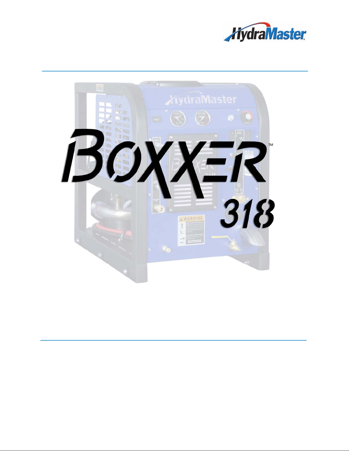
Boxxer 318
Owner’s Manual
HydraMaster North America, Inc.
11015 47th Avenue West, Mukilteo, Washington 98275
MAN-44101 Rev. 0, February 26, 2010
No part of this manual may be reproduced or used in any form or by any means (i.e. graphic, electronic, photocopying
or electronic retrieval systems) without the express written permission of HydraMaster North America, Inc.
All rights reserved. © 2010 HydraMaster North America, Inc.
(182-076-D)
Page 2

Table of Contents
GeNeRAl INFORMATION ...........................................................................SeCTION 1
Contact Information ................................................................................. 1-2
Warnings, Cautions and Notices ............................................................. 1-3
Machine Specications ........................................................................... 1-10
Spare Parts list ......................................................................................1-11
High Altitude Operation ..........................................................................1-12
local Water Precautions .........................................................................1-12
CleANING AND CHeMICAlS .....................................................................SeCTION 2
Precautions .............................................................................................2-1
Preparing the Carpet for extraction.........................................................2-2
Rinse and Recover..................................................................................2-2
Overwetting .............................................................................................2-3
Streaking .................................................................................................2-3
Cleaning Tool Tips ...................................................................................2-4
SySTeM OPeRATION .................................................................................SeCTION 3
Start-up Procedure .................................................................................. 3-1
Shut Down Procedure .............................................................................3-4
MACHINe MAINTeNANCe ..........................................................................SeCTION 4
Operational Maintenance ........................................................................4-2
Overall Machine Maintenance.................................................................4-3
High Pressure Pump Maintenance ......................................................... 4-4
Vacuum System Maintenance ................................................................. 4-8
Descaling Procedure (Required) ............................................................. 4-9
Freeze Guarding .....................................................................................4-10
Tensioning the Pump Drive Belt ..............................................................4-12
WATeR AND CHeMICAl SySTeM ............................................................SeCTION 5
Water and Chemical Flow Operation ......................................................5-1
eleCTRICAl SySTeM ................................................................................SeCTION 6
TROuBleSHOOTING .................................................................................SeCTION 7
Heating System ....................................................................................... 7-2
Chemical System ....................................................................................7-3
engine .....................................................................................................7-4
High Pressure System ............................................................................ 7-7
Vacuum System ...................................................................................... 7-9
i: Boxxer 318 Owner’s Manual
Page 3

8 - MACHINe ASSeMBlIeS AND PARTS lIST...........................................SeCTION 8
Machine Assembly Parts list ..................................................................8-4
Frame Assembly Parts list .....................................................................8-8
engine Assembly Parts list..................................................................... 8-10
Blower Assembly Parts list .....................................................................8-11
Pump Assembly Parts list ......................................................................8-12
Chemical Pump Assembly Parts list ......................................................8-13
Heat exchanger Assembly Parts list ...................................................... 8-14
Silencer Assembly Parts list ...................................................................8-15
Water Box Assembly Parts list ...............................................................8-17
Dash Assembly Parts list .......................................................................8-20
Hi-PSI Manifold Assembly Parts list .......................................................8-22
By-Pass Valve Assembly Parts list .........................................................8-23
Idler Pulley Assembly Parts list .............................................................. 8-24
exhaust Assembly Parts list ...................................................................8-25
electrical Panel Assembly Parts list ....................................................... 8-26
50 Gallon universal Recovery Tank Assembly Parts list ........................8-28
70 Gallon universal Recovery Tank Assembly Parts list ........................8-30
Cover, Single Vac. - 70 Gallon uRT Assembly Parts list........................ 8-31
Vacuum Relief Valve Assembly Parts list ...............................................8-32
Dura-Flow APO 90° Assembly Parts list ................................................ 8-33
APO Connection Kit Assembly Parts list ................................................8-34
Boxxer 318 on 85 RMT w/ 50 uRT Assembly Parts list .........................8-37
50 Gallon uRT for 85 RMT Assembly Parts list .....................................8-39
Boxxer 318 on 85 RMT w/ 70 uRT Assembly Parts list .........................8-42
70 Gallon uRT for 85 RMT Assembly Parts list .....................................8-44
85 Gallon Rotomolded Tank Assembly Parts list ................................... 8-47
Dump and Vacuum Assembly Parts list ................................................. 8-48
Chemical Jug Tray Assembly Parts list ..................................................8-49
Machine Hose Routings ..........................................................................8-50
HOW TO ORDeR PARTS ............................................................................SeCTION 9
Warranty Parts Orders ............................................................................9-1
Parts Orders ............................................................................................ 9-1
emergencies ...........................................................................................9-1
Boxxer 318 Owner’s Manual: ii
Page 4

WARRANTy INFORMATION .......................................................................SeCTION 10
Blower
High Pressure Water Pump
....................................................................................................10-1
...................................................................10-1
Vacuum Tank .......................................................................................... 10-2
Chemical System ...................................................................................10-2
Control Panel ......................................................................................... 10-2
Vacuum and Solution Hoses
Cleaning Wand
....................................................................................... 10-2
.................................................................. 10-2
Water Heating System ...........................................................................10-2
Hard Water Deposits .............................................................................. 10-2
Warranty Procedure ................................................................................10-3
ACCeSSORIeS AND CHeMICAl SOluTIONS ..........................................SeCTION 11
iii: Boxxer 318 Owner’s Manual
Page 5

list of Figures
Figure 1-1. Hard Water Map of Mainland united States .....................................1-13
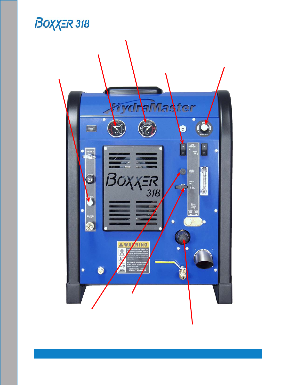
Figure 3-1. location of Throttle, Choke, Optional Pump-In
Switch and Water Box ........................................................................3-1
Figure 3-2. Front View of Boxxer 318 Console .....................................................3-2
Figure 4-1. Servicing the Valves ...........................................................................4-5
Figure 4-2. Recirculation Fitting ............................................................................4-9
Figure 5-1. Annotated Water, Chemical and Solution
Flow Diagram - View 1 of 2 ................................................................5-2
Figure 5-2. Annotated Water, Chemical and Solution
Flow Diagram - View 1 of 2 ................................................................5-3
Figure 5-3. Annotated Chemical Flow Diagram ...................................................5-4
Figure 5-4. exhaust Flow Diagram.......................................................................5-5
Figure 6-1. electrical Schematic ...........................................................................6-2
Figure 6-2. Wiring Diagram - View 1 of 3 ..............................................................6-3
Figure 6-3. Wiring Diagram - View 2 of 3 ..............................................................6-4
Figure 6-4. Wiring Diagram - View 3 of 3 ..............................................................6-5
Figure 8-1. Machine Assembly - Front left View ..................................................8-2
Figure 8-2. Machine Assembly - Front Right View ................................................8-3
Figure 8-3. Frame Assembly - Front left View ......................................................8-5
Figure 8-4. Frame Assembly - Front Right View ...................................................8-6
Figure 8-5. Frame Assembly - Rear View .............................................................8-7
Figure 8-6. engine Assembly ................................................................................8-9
Figure 8-7. Blower Assembly ..............................................................................8-11
Figure 8-8. Pump Assembly ................................................................................8-12
Figure 8-9. Chemical Pump Assembly ................................................................8-13
Boxxer 318 Owner’s Manual: iv
Page 6

Figure 8-10. Heat exchanger Assembly..............................................................8-14
Figure 8-11. Silencer Assembly
Figure 8-12. Water Box Assembly
...........................................................................8-15
.......................................................................8-16
Figure 8-13. Dash Assembly - Front ...................................................................8-18
Figure 8-14. Dash Assembly - Back ....................................................................8-19
Figure 8-15. Hi-PSI Manifold Assembly ..............................................................8-21
Figure 8-16. By-Pass Valve Assembly
................................................................8-23
Figure 8-17. Idler Pulley Assembly......................................................................8-24
Figure 8-18. exhaust Assembly ..........................................................................8-25
Figure 8-19. electrical Panel Assembly...............................................................8-26
Figure 8-20. 50 Gallon universal Recovery Tank Assembly ...............................8-27
Figure 8-21. 70 Gallon universal Recovery Tank Assembly ...............................8-29
Figure 8-22. Cover, Single Vac. - 70 Gallon uRT Assembly ...............................8-31
Figure 8-23. Vacuum Relief Valve Assembly ......................................................8-32
Figure 8-24. Dura-Flow APO 90° Assembly ........................................................8-33
Figure 8-25. APO Connection Kit Assembly........................................................8-34
Figure 8-26. Boxxer 318 on 85 RMT w/ 50 uRT Assembly - Right View ............8-35
Figure 8-27. Boxxer 318 on 85 RMT w/ 50 uRT Assembly - left View ...............8-36
Figure 8-28. 50 Gallon uRT for 85 RMT Assembly .............................................8-38
Figure 8-29. Boxxer 318 on 85 RMT w/ 70 uRT Assembly - Right View ............8-40
Figure 8-30. Boxxer 318 on 85 RMT w/ 70 uRT Assembly - left View ...............8-41
Figure 8-31. 70 Gallon uRT for 85 RMT Assembly .............................................8-43
Figure 8-32. 85 Gallon Rotomolded Tank Assembly - Front View .......................8-45
Figure 8-33. 85 Gallon Rotomolded Tank Assembly - Back View .......................8-46
Figure 8-34. Dump and Vacuum Bracket Assembly ............................................8-48
Figure 8-35. Chemical Jug Tray Assembly..........................................................8-49
v: Boxxer 318 Owner’s Manual
Page 7
1- General Information
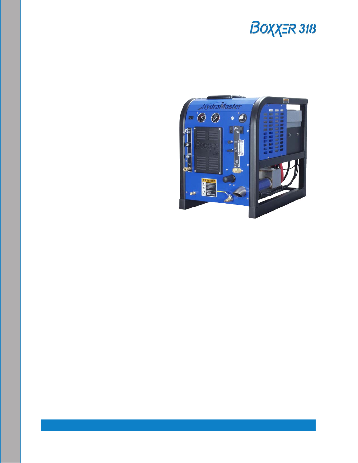
The Boxxer™ 318 is a carefully engineered truckmount designed by HydraMaster
Corporation.
The system utilizes an internal combustion
engine to provide the power necessary to
turn both a blower (also referred to as a
vacuum pump) and a high pressure water
pump.
The heat of the engine and blower
exhausts is transferred to the high
pressure water in the nned tube heat
exchanger of the system.
Finally, the chemical is injected into the
pressurized water stream and the heated
solution is delivered to the cleaning tool.
The solution is recovered by the vacuum generated by the blower and is collected in the
recovery tank for proper disposal.
It is the purpose of this manual to help the technician properly understand, maintain and
service the truckmount. By following these guidelines carefully, you can expect years of
reliable operation.
This section contains the following helpful information:
Contact Information
Warnings, Cautions, and Notices
Responsibilities
Machine Specications
Spare Parts lists
High Altitude Operation
local Water Precautions
1-1: General Information
Page 8
COntaCt InfOrMatIOn
If you have any questions regarding the operation, maintenance or repair of this machine,
please contact your local distributor.
To nd a local distributor, please visit our website at http://www.hydramaster.com/owners/
locate/index.asp.
If your question cannot be resolved by your distributor or by the information within this
manual, you may contact HydraMaster Customer Service direct using the following phone
numbers or e-mail addresses.
Hours telephone numbers E-mail addresses
Monday-Friday (425) 775-7275 Service
7:00 a.m. to 5:00 p.m. (425) 775-7276 Parts
Pacic Standard Time
(800) 426-4225 Parts /
Service FAX
techsupport@hydramaster.com
partssupport@hydramaster.com
Tech Support:
Parts Support:
When calling your distributor, be sure to reference the serial number and the date of
purchase.
fOr YOUr rEfErEnCE:
Serial number: _______________________________________________
Date of Purchase:_____________________________________________
Purchased from (Distributor): __________________________________
General Information: 1-2
Page 9

WarnIngS, CaUtIOnS anD nOtICES
HydraMaster uses this WARNING symbol throughout the manual to warn of
possible injury or death.
This CAuTION symbol is used to warn of possible equipment damage.
This NOTICe symbol indicates that federal or state regulatory laws may apply,
and also emphasizes supplemental information.
1-3: General Information
Page 10

During the operation of the truckmount many components are in motion. Never touch any
part of the truckmount that is in motion. Serious injury may result.
During the operation of the truckmount many surfaces will become extremely hot. Never
touch hot surfaces. Serious injury may result.
The operation of this truckmount can produce noise levels exceeding 85 decibels
to a distance of 10 feet. The Occupational Safety and Health Administration (OSHA)
recommends the use of hearing protective equipment if a person is exposed to an average
of 85 decibels over an eight hour period. Check with local and state agencies concerning
hearing conservation rules.
During the operation of the truckmount carbon monoxide and other toxic fumes are
produced. Position the vehicle so that any fumes produced will be directed away from
inhabited areas and any points of building entry (doors, windows, air conditioning units,
fans, etc.). Do not occupy the vehicle while the truckmount is in operation. Serious injury
may result.
During the operation of the truckmount chemicals known to the State of California to cause
cancer, birth defects and other reproductive harm are produced by the engine exhaust.
Never operate the truckmount with a portable gas container inside the vehicle. Doing so
will increase the risk of re and explosion. Serious injury or death my result.
Transporting a vented fuel container that presently contains, or has ever contained in
the past, a ammable liquid is strictly forbidden by HydraMaster and by federal and state
regulations. Doing so will increase the risk of re and explosion. Serious injury or death
may result.
General Information: 1-4
Page 11
Never smoke in or around the truckmount. Doing so will increase the risk of re and
explosion. Serious injury or death may result.
During the operation of the truckmount the exhaust system will become extremely hot.
Keep all ammable materials away from the truckmount exhaust system. Failure to do so
will increase the risk of re and explosion. Serious property damage may result.
Never operate the truckmount when the vehicle is tilted more than 10 degrees in any
direction. Doing so will result in improper lubrication of the internal components, and will
increase the risk serious component or engine damage.
Never perform cleaning operations when the truckmount engine is running at the IDle
throttle position. Failure to do so will increase the risk of serious component or engine
damage.
Never operate the truckmount with the vehicle doors closed. Doing so results in extremely
high temperatures inside the vehicle and will lead to serious component or engine
damage.
Never use concentrated acids or solvents (including d-limonene) in the truckmount
water system or chemical system. use of these products will cause serious component
damage.
Never operate the truckmount with a water hardness reading measuring 3.0 grains per
gallon or higher. using reading than 3.0 grains per gallon will cause scale to build up
inside the truckmount water system. Scale build up causes serious component damage.
Test all water prior to use and use water softening equipment if necessary.
1-5: General Information
Page 12

Never allow water to freeze inside the truckmount. Serious component damage will occur.
Perform all freeze guarding procedures outlined in this digital Owner’s Manual.
Many vehicles have critical components mounted directly below the oor that can easily
be damaged. Before drilling holes in the oor of the vehicle, inspect the underside of the
vehicle for critical components. Failure to do so may result in damage to the vehicle.
General Information: 1-6
Page 13
rESPOnSIBIlItIES
the Purchaser’s responsibilities
Prior to purchasing a van, ensure that the payload is suitable for all of the equipment
that will be installed and transported. This includes and is not limited to: the truckmount,
recovery tanks, fresh water tanks, on-board water, hose reels, hoses, cleaning tools,
chemicals, drying equipment, etc. Payload capacity information is available through the
auto dealer, the manufacturer’s web site, and is also located on the door pillar of the
driver’s side door.
Purchase a heavy duty Group 24 battery for this truckmount. This is normally available
from the installation dealer.
Prior to dropping your van off at the distributor for the truckmount to be installed, have a
spray-on bed liner applied to the oor such as Rhino Lining® or Line-X®.
Prior to operating the truckmount read this manual in its entirety and familiarize yourself
with the information contained here. Special attention should be paid to all cautions and
warnings.
The distributor is responsible for the correct installation of the truckmount. The distributor
is also responsible to train you in the correct and proper operation and maintenance of
the truckmount.
Any modication of the truckmount may void the warranty.
the Distributor’s responsibility
acceptance of Shipment
Before accepting the truckmount, check the following:
The truckmount should be free from any damage during shipping. Do not sign the
•
delivery receipt until you have closely inspected the truckmount and noted any damage
on the delivery receipt. Hidden damage may be present even if the box looks okay. It
is recommended that the box be opened before signing for the shipment.
Check the packing list and verify that all items are accounted for.
•
1-7: General Information
Page 14

Installation responsibilities
ensure proper payload capacity. It is the distributor’s responsibility to verify that the •
equipment package does not exceed the vehicle capacity.
Ensure installation of a safe fuel tap system and through-oor ttings as provided by
•
HydraMaster.
Proper placement of the truckmount, recovery tank, fresh water tank, and accessories
•
in the vehicle and securing them with bolts and back up plates. The distributor should
verify that the owner is in agreement with the layout.
ensure proper connection of the fuel lines.•
ensure proper connection and installation of the battery. Verify that the battery is in •
accordance with HydraMaster’s recommendation.
Check the pump, vacuum blower and engine oil levels prior to starting the
•
truckmount.
Start and run the truckmount and check that all systems function properly.
•
Test all hoses, wands, etc. for correct operation.•
ensure timely return of the document package.•
General Information: 1-8
Page 15

training
The distributor should provide a thorough review of the operation manual with the
purchaser along with instruction and familiarization in:
How all the truckmount’s systems function.
•
All safety precautions and their importance.•
How to correctly start and shut down the truckmount.•
How to correctly clean with the truckmount.•
Where and how often to check and change component oil levels.•
Freezing damage and how to avoid it. This includes explaining proper freeze guarding •
procedures.
How to do basic troubleshooting of the truckmount.
•
Hard water damage and how to avoid it. This includes how to determine if hard water •
exists in your area and the installation and use of water softening systems.
The truckmount’s warranty and warranty procedures.
•
1-9: General Information
Page 16
MaCHInE SPECIfICatIOnS
Overall Dimensions 24.0" W x 36" D x 31" H
Weight 570 lbs.
engine- Briggs and
Stratton Vanguard 18 HP
Vacuum Blower- Tuthill
3006 Competitor Plus Sl
(Dual Splash lubrication)
Pump- HydraPump II Oil Type Synthetic 15W-50
Operating Pressure 0 - 1,000 psi
Chemical System
Heating System Finned Tube Heat exchanger
Standard equipment High Pressure Hose 1/4" High Temperature lined/
Optional equipment Recovery Tank 70 gallon MaxAir universal
Oil Type Synthetic 5W-30
Capacity Approx. 1 1/2 quarts (48 oz.)
when changing oil and lter
engine rpm 3,150 rpm @ 14" Hg
Oil Type Pneulube or other ISO 100
rating
Gear end Capacity Approx. 7.0 oz.
Drive end Capacity Approx. 5.0 oz.
Blower rpm 3,150 rpm @ 14" Hg
Capacity Approx. 8.0 oz.
Pump Rate 3.5 gallons per minute
Pump rpm 1,750 rpm
last Step Chemical Injection
Vinyl Cover - 100 ft.
Vacuum Hose 2" Vacuum Hose- 100 ft.
1-1/2" Wand Whip line- 10 ft.
Recovery Tank 50 gallon MaxAir universal
Tank
Cleaning Wand Stainless Steel S-bend
Replaceable Grip
Rebuildable Solution Valve
Chemical Jug 5 gallon
Battery Box
Van Decal
Van Installation Kit
Operation Manual
Tank
Fresh Water Tank 85 gallon Rotomolded Tank
Automatic Pump Out (APO) Dura-Flow APO
General Information: 1-10
Page 17
Spare partS LiSt
part No. Description Qty
Engine and Drive Train Components
000-106-016 Plug, Spark 2
000-049-049 Filter, Fuel 1
000-049-014 Filter, Oil 1
000-049-012 Filter, Air 1
000-010-125 Belt, 9440HD 1
000-152-011 Coupler Element 1
Electrical Components
000-056-010 Fuse, 25A 2
000-157-040 Switch, 20 Amp Rocker 2
000-157-022 Switch, Relay, 12V 2
Hydraulic Components
000-052-050 Quick Connect, 440 Male 2
000-052-051 Quick Connect, 440 Female 2
000-052-052 Quick Connect, 660 Male 1
000-052-053 Quick Connect, 660 Female 1
000-046-010 Diaphragm, Chemical Pump 1
000-169-186 Valve, 100 psi, Last Step Chemical 1
000-180-006 Orice, 0.061 dia. 1
000-180-004 Orice, 0.033 dia. 1
000-074-007 Gauge, High psi (0-1,500) 1
000-049-023 Screen, Garden Hose 1
000-078-273 Kit, By-Pass Valve Repair w/Tapered
Handle
1
Miscellaneous
000-087-006 HydraMaster-Recommended Spray
Lubricant (part number is for a quantity of
1 can)
1-11: General Information
1 ea
Page 18

HIgH altItUDE OPEratIOn
elevation plays a key role in how the truckmount will operate. Operation at high altitude
(above 5,000 ft.) may require a high-altitude carburetor jet. use of this jet at high altitude
will improve power, reduce fuel consumption and help reduce excessive carbon build-up
in the exhaust and heat exchanger systems.
Contact the local Briggs and Stratton dealer or HydraMaster to obtain the proper jet
size. your local Briggs and Stratton dealer can be located at http://vanguardengines.via.
infonow.net/locator/.
lOCal WatEr PrECaUtIOnS
The quality of water varies greatly. Many areas have an excess of minerals in the water
which results in what is commonly called “hard water.” These minerals tend to adhere to
the insides of heater coils and other parts of the machines causing damage and a loss of
cleaning effectiveness. This inuences the reliability and efciency of equipment in direct
proportion to the level of hardness.
Hard Water advisory
HydraMaster recognizes that any hard water deposits which might occur within the water
system of our truckmounts is a serious problem. The precision technology of truckmount
heat exchanger systems is intolerant of any foreign material. Hard water deposits will
ultimately decrease the performance of the system and are expected to seriously lower
the reliability of the machine.
To validate a machine’s warranty, HydraMaster requires that all machines operating in
designated “Hard Water Areas” (3.0 grains or more per gallon) be tted with a water
softening system, or a properly installed magnetic-type descaler must be used and
maintained. Periodic descaling or acid-rinsing alone is not adequate in these areas.
HydraMaster does not recommend any particular type or brand; however, the relative
effectiveness of some types of magnetic descalers or softeners may require additional
periodic use of descaling agents.
HydraMaster also recommends, in the strongest possible terms, that machines in all areas
be tted with a water softening system for improved operation and reliability.
Failure to take appropriate measures to prevent scale build up can result in
system failure and loss of warranty on affected parts.
General Information: 1-12
Page 19

Hard Water area Map
The hard water map, shown in Figure 1-1, denes hard water areas in the continental
United States which compromise uid related components such as hoses, ttings, heaters,
pumps, valves and water-cooled engines. For other countries, hard water area maps can
be obtained from geological societies.
Hard Water Map of Mainland United Statesfigure 1-1.
The map shown in Figure 1-1 is provided for general reference only. Water
hardness in your geographical location should be conrmed by testing.
Water Softener
Cleaning efciency and equipment life is increased, chemical use decreased, and the
appearance of cleaned carpets enhanced when water softeners are incorporated in
hard water areas. HydraMaster strongly urges the use of water softener units with the
Boxxer 318 in areas exceeding 3.0 grains per gallon.
Failure to use a water softener in these areas will invalidate the machine’s warranty.
Referring to the hard water area map shown Figure 1-1, determine the quality of water
in your area and take immediate action if the water hardness exceeds 3.0 grains per
gallon.
The relatively low cost of a water softener service is more than made up for by an increased
life of machine parts, reduced chemical costs and continued cleaning efciency. The
water softener will also increase the effectiveness of the cleaning chemicals, therefore
less chemical will be needed.
1-13: General Information
Page 20

Contact a water softener distributor in your area for information on the rental of a simple
water treatment unit to carry in your truck. Be sure to charge the water softener in
accordance with the capability of the softener.
For example: If the softener will treat 900 gallons of water and the machine uses an
average of 30 gallons/hour, for an average of 5 hours a day, this equals 150 gallons per
day). In 6 days the machine would use 900 gallons of water. Therefore, the softener
would need to be charged every 6 working days for maximum softening.
Waste Water Disposal advisory
There are laws in most communities prohibiting the dumping of recovered “gray” water
from carpet cleaning in any place but a sanitary treatment system.
The cleaning rinse water, recovered into your unit’s vacuum tank, contains materials
such as detergents, and must be safely processed before entering streams, rivers and
reservoirs.
In most cases, an acceptable method of waste water disposal is to discharge into a
municipal sewage treatment system after rst ltering out solid material such as carpet
ber. Access to the sanitary system can be obtained through a toilet, laundry drain, RV
dump, etc. Permission should rst be obtained from any concerned party or agency.
One disposal method which usually complies with the law is to accumulate the waste
water and haul it to an appropriate dump site. Another solution to the disposal problem
is to equip your Boxxer 318 with an Automatic Pump-Out System (APO). These systems
are designed to remove waste water from the extractor’s recovery system and actively
pump the water through hoses to a suitable disposal drain.
HydraMaster makes an APO System which can be ordered with new equipment or
installed later.
When properly congured, the systems will continuously monitor the level of waste water
and pump it out simultaneously with the cleaning operation. The hidden benet of this
process is that the technician does not have to stop his/her cleaning to empty the recovery
tank.
IN ACCORDANCe WITH ePA, STATe AND lOCAl lAWS, DO NOT DISPOSe OF
WASTe WATeR INTO GuTTeRS, STORM DRAINS, STReAMS, ReSeRVOIRS,
eTC.
The penalties for non-compliance can be serious. Always check local laws and
regulations to be sure you are in compliance.
General Information: 1-14
Page 21

2 - Cleaning and Chemicals
your HydraMaster truckmount has been engineered using the latest and most sophisticated
technology available to produce the nest carpet cleaning results possible. Despite this,
it remains only a tool of the carpet cleaning trade and can produce only as a good a job
as the person operating it.
HydraMaster strongly recommends attending an Institute of Inspection, Cleaning
and Restoration Certication (IICRC) approved school as soon as possible and to
always follow the IICrC guidelines when cleaning.
This section describes the carpet cleaning procedure in the following areas:
Precautions
Preparing the Carpet for extraction
Rinse and Recover
Overwetting
Streaking
PrECaUtIOnS
The use of some chemicals (such as concentrated acids and/or solvents) in your truckmount
can seriously damage the internal plumbing and high pressure pump.
HydraMaster strongly recommends purchasing a water softener to prevent the buildup of
scale and hard water deposits in your truckmount.
HydraMaster recommends only the use of chemicals containing rust and corrosion
inhibitors and water softening agents to prevent chemical buildup which may lead to
component failure and warranty invalidation.
Increased demand for a neutralizing rinse results in the need for special care
when using these acid based chemicals in your truckmount The negative side
of these products is the corrosive effects the acid can have on metals, including
ttings, pumps, heat exchangers, etc.
HydraMaster’s ClearWater Rinse™ has been formulated to protect vital components.
HydraMaster will not warranty parts that have been damaged from using acid products
that have obviously caused failures.
2-1: Chemicals and Cleaning
Page 22

PrEParIng tHE CarPEt fOr ExtraCtIOn
Pre-Vacuum the Carpet
Whether you instruct the customer to pre-vacuum or you offer it as part of your service,
proper vacuuming will make your job easier with superior end results. The more time
spent removing loose particulate soil, the easier it will be to remove the oily soil stuck to
the bers.
Pretreat the Carpet
This process of applying trafc lane type chemicals to the carpet (whether by sprayer or
rotary scrubber) is essential prior to extraction with your truckmount.
By applying cleaning agents to the carpet and letting them dwell 10-20 minutes prior to
rinsing, you allow the product to dissolve and emulsify the oily, sticky binders holding the
soil to the ber. This will allow more soil to be removed in one or two cleaning passes and
help prevent over-wetting.
Remember the solution coming out of your cleaning tool is only in contact with the carpet
ber for a few seconds. Relying on the rinse detergent to do the majority of the cleaning
will result in overly long dry times and excess detergent residue left in the carpet.
HydraMaster recommends the use of our pre-sprays: Fastbreak™ for residential carpet
and Blitz™ for commercial carpet needs.
rInSE anD rECOVEr
Whether you are using a wand, RDM™ or an RX-20™, you should clean an area
approximately 3 ft. x 3 ft. with the solution valve open then immediately go over that area
with vacuum only to remove any excess moisture.
Olen ber is becoming more popular, particularly in commercial installations. The
process mentioned above can leave excessive residual moisture because olen
bers will not absorb any of the cleaning solution. You must only apply solution
during the backward stroke of the wand so it can be immediately captured by the
vacuum head. RX-20™ and RDM™ users should follow each pass with a dry
pass. Failure to follow this procedure will cause solution to ow to the back of
the carpet along with some of the soil. This, along with any soil imbedded in the
backing, will be wicked to the surface of the bers as the carpet dries.
HydraMaster recommends the following rinse aids: Alkaline - Hydra-Dri Powder™ or
Hydra-CleanLiquid™. Acid - Clear Water Rinse™.
Chemicals and Cleaning: 2-2
Page 23

OVErWEttIng
Overwetting is an annoyance to all concerned. extended drying times will leave the
customer with a negative impression of both the cleaning company and the process
used.
There are several factors that will cause over-wetting:
Too few vacuum strokes.
1.
Clogged vacuum blower lter or vacuum tank lid not sealing properly.2.
Vacuum tank drain valve left partially open.3.
Obstructed, cut or kinked vacuum hoses.4.
Obstructed vacuum hoses while cleaning a heavily foam-saturated carpet (it is 5.
recommended to use a crystal type defoamer distributed evenly over the carpet).
StrEakIng
Streaks in the carpet can appear in both clean or dirty areas and normally appear in
heavily soiled, light colored carpets.
Possible reasons of streaking may include:
Clogged or improperly angled spray nozzles.
1.
Spray nozzles that overlap, concentrating the solution.2.
A partially clogged vacuum head.3.
Inconsistent solution temperature.4.
2-3: Chemicals and Cleaning
Page 24

ClEanIng tOOl tIPS
Wands
With a wand, keep cleaning strokes short, front to back, and run a “dry pass”.
After pulling the wand for a strip of 3 or 4 ft long with the solution trigger activated, go back
up to the top of the stroke, and make a “dry “ pass [i.e. no solution owing]. This gives the
wand a second chance to pick up the solution on the carpet.
If you do not run a dry pass, the carpet can take longer to dry, and, possibly, the pad under
the carpet can become saturated.
Be aware of the carpet seams; try to use strokes that are parallel with the seam. Avoid
pulling the want across the seam. every stroke can peel the seam connection and pull
the carpet off the oor.
Also, tilt the wand handle down [head up] to move the tool forward, and away from you,
on the carpet. This means less pull on the carpet and less work for you.
Chemicals and Cleaning: 2-4
Page 25
2-5: Chemicals and Cleaning
Page 26
Chemicals and Cleaning: 2-6
Page 27
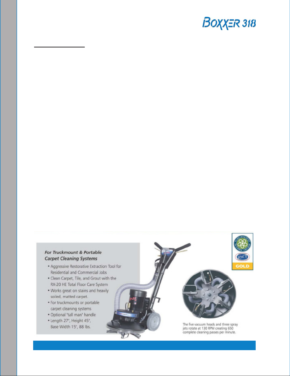
rotary tool: rx-20
Rotary tools are easier to move on the carpet, but harder to control at rst. With a rotary
tool, remember to keep strokes short and side-to-side.
Before turning on the RX-20, adjust the handle; it should rest right below or even with the
bottom of your pants’ front pockets, with the tool resting at on the oor. Take your time
in adjusting the tool’s height; make sure the head of the tool is at with the oor while you
are holding the handle. Relax your posture; the more difcult it is to hold the tool’s head
at on the oor surface, the more quickly you will tire.
While the tool is running, control the left and right movements of the tool by tilting the head
to the front and back, and lifting the handles up and pushing the handles down. The tool
can be driven to the forward and backward by tilting the head of the unit to the left and
right. The head must be turning to use the self driving feature of the tool, and only requires
a slight bit of pressure to handles to get the head to move the tool across the oor.
As with the wand, drying times will be improved if you run a dry pass between wet passes.
Hold down the solution trigger and move the unit left or right across the oor 3 or 4 ft, then
immediately back across the same pass, without the solution owing, to make the dry
pass. Make the next pass half-overlapping the previous pass.
Use the RX-20 in very heavily trafcked areas or if it has been a long time since the carpet
has been cleaned. Beware of the seam edges of carpets and transition edges between
oor surfaces. Use extreme caution when cleaning these areas.
Sometimes it is necessary to use an edge tool or wand to run the perimeter of the room
on in difcult-to-reach areas where the circular head of the rotary units will not reach.
2-7: Chemicals and Cleaning
Page 28
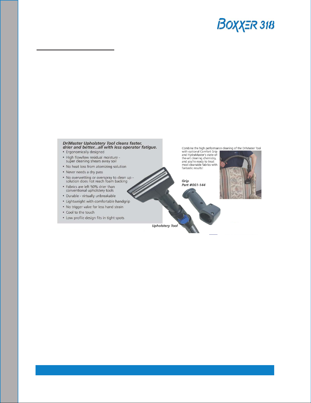
Upholstery tool: DriMaster
use the upholstery tool on small rugs and furniture. When you clean rugs, be sure that the
temperature and chemicals are safe for that particular type of rug.
As with the larger tools, do not leave the surface of the upholstery too wet. Adjust the
volume of water on the tool without it touching any surface: the water should just barely
come out of the tool before the vacuum pulls it back in. The water will only just spray the
top layer of the furniture and the vacuum will pull the dirty water back into the tool.
If you nd it necessary to do a dry pass, keep strokes short to limit the amount of water
that comes into contact with the fabric surface.
Chemicals and Cleaning: 2-8
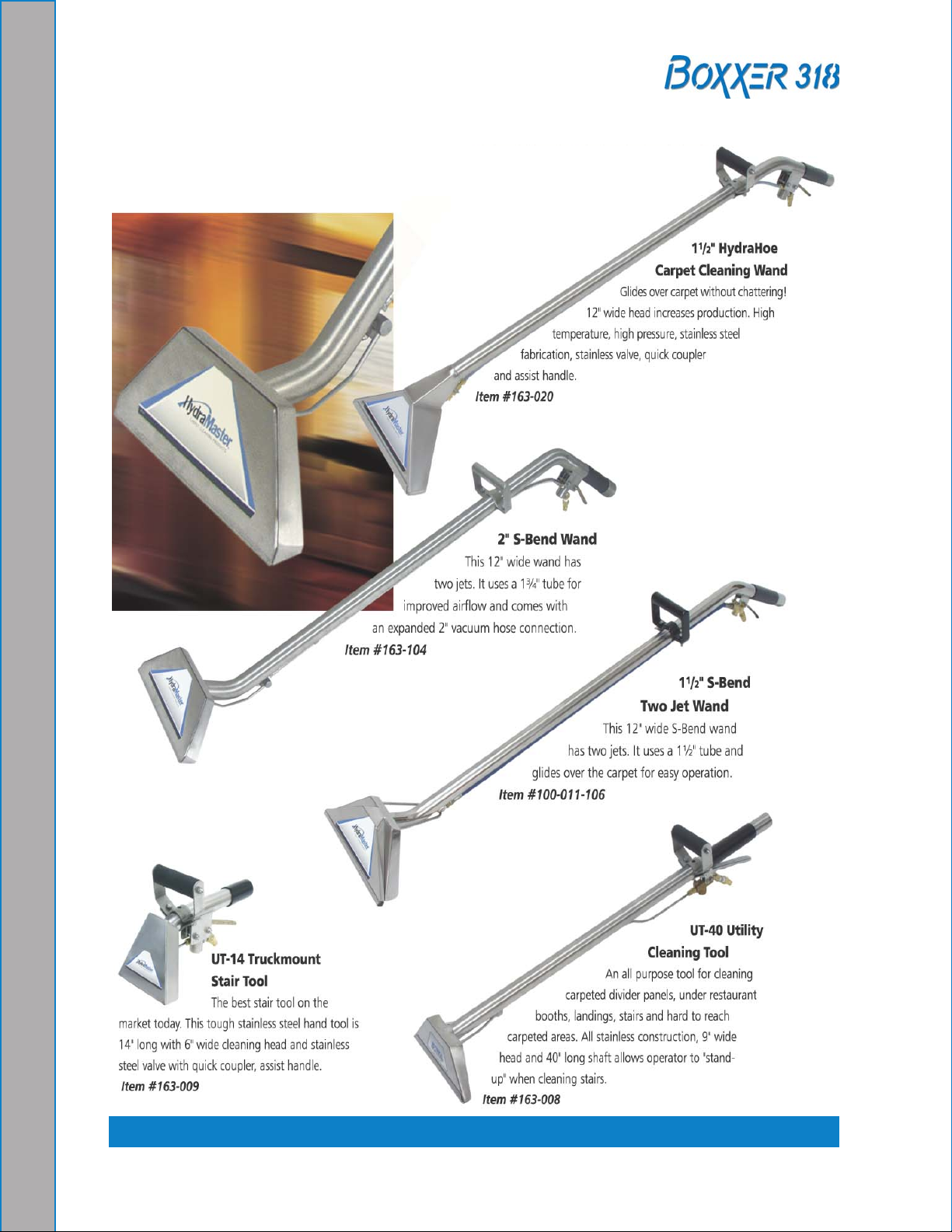
Part #163-012
Page 29
3 - System Operation
Start-UP PrOCEDUrE
Perform all daily and periodic maintenance as specied in Section 1. 4 of this Owner’s
Manual.
Connect a garden hose to supply water to the truckmount. If used, turn the “PuMP-IN” 2.
switch to the “ON” position.
The water box must be full prior to starting the truckmount.
Connect the cleaning tool to the length of hose required to perform the cleaning 3.
job.
Turn the key to “ON”. Pull the choke and start the truckmount with the throttle cable
4.
fully depressed (“IDle” position.)
After the engine starts, push the choke in and allow the truckmount to run in “IDle” 5.
for 2 - 3 minutes to warm up.
Pull the throttle cable to full extension and twist the handle clockwise to lock.
6.
Set the temperature to the desired level on the “TeMPeRATuRe” knob.7.
If used, turn the “AuTO PuMP-OuT” switch to the “ON” position.8.
throttle
Choke
location of throttle, Choke, Optional Pump-In Switch and Water Boxfigure 3-1.
Optional
Pump-In Switch
Water Box
3-1: System Operation
Page 30
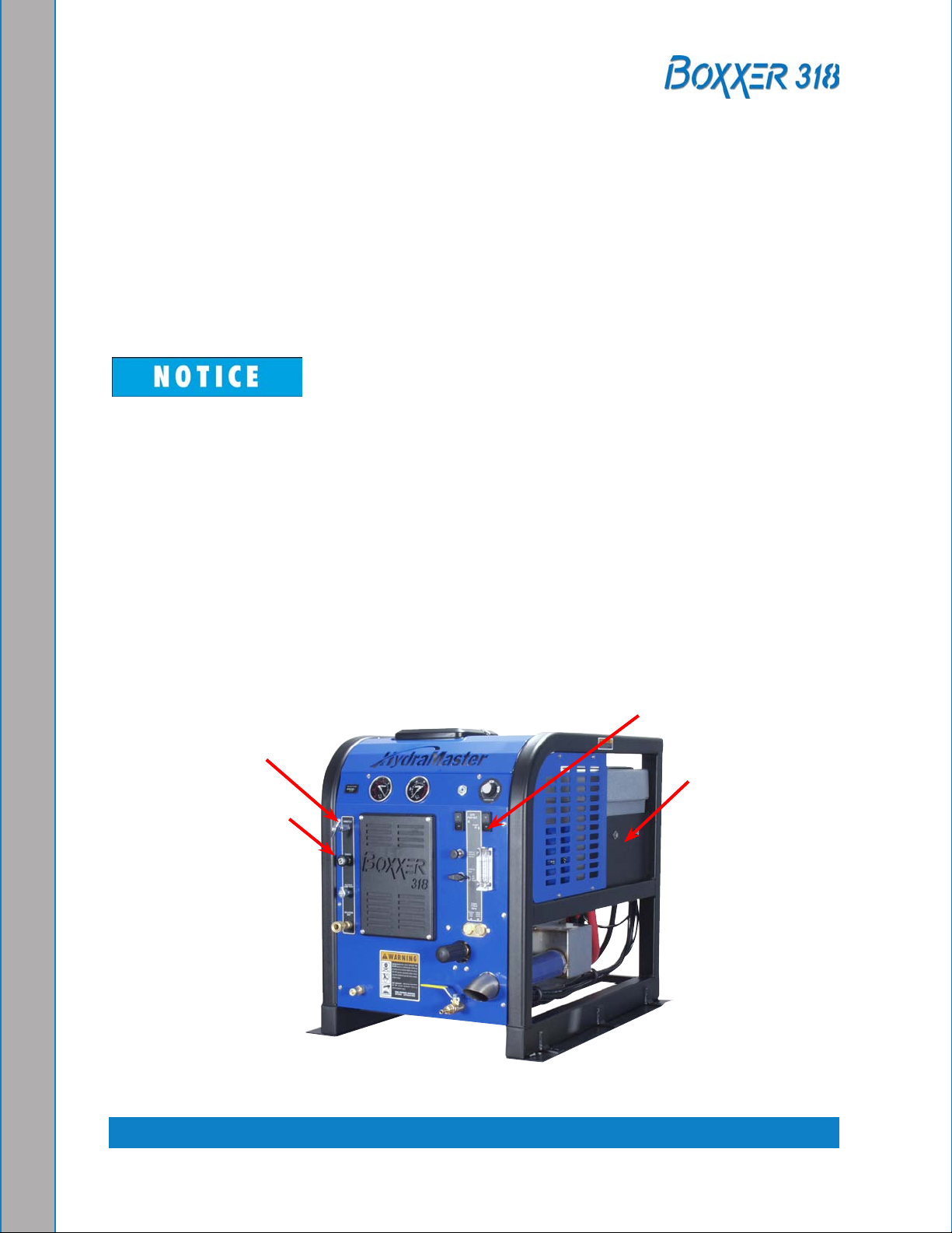
Vacuum gauge
Pressure gauge
Blower lube
Port
Optional auto
Pump-Out Switch
temperature knob
Chemical Selection Valve
Chemical Metering Control knob
System Operation: 3-2
Pressure regulator
front View of Boxxer 318 Consolefigure 3-2.
Page 31

Adjust the “PReSSuRe ReGulATOR” to the desired cleaning pressure level.9.
Suggested Settings:a.
Carpet Cleaning: 300 - 400 psi
Hard Surface Cleaning: 1,000 psi or as indicated on the tool
Turn the “CHeMICAl SeleCTION VAlVe” to the “PRIMe” position to purge any air 10.
from the system.
With the truckmount running at full throttle, block off the vacuum intake to the
a.
recovery tank. The vacuum gauge should read 12”-14” Hg. This will assist in
priming the chemical system.
Allow the chemical to ow through the chemical meter at full ow for 30
b.
seconds.
Turn the “CHeMICAl SeleCTION VAlVe” to “ON.” The restriction can now be c.
removed from the vacuum inlet.
While spraying solution from the cleaning tool adjust the chemical ow by turning
d.
the “CHeMICAl MeTeRING CONTROl KNOB”.
Begin cleaning.11.
Never perform cleaning operations when the truckmount engine is running at the
IDle throttle position. Failure to do so will increase the risk of serious component
or engine damage.
3-3: System Operation
Page 32

SHUt DOWn PrOCEDUrE
Flush clean water through the chemical system for 10 seconds. Turn the “CHeMICAl 1.
SeleCTION VAlVe” to “OFF.”
Cool the truckmount down by turning the “TeMPeRATuRe CONTROl” dial to the 2.
lowest position (counter-clockwise). Spray the cleaning wand into the vacuum hose
for 3 - 5 minutes. The chemical is now ushed from the truckmount, hoses and
cleaning tool.
Remove the vacuum hose.
3.
lubricate the blower to prevent it from rusting internally.4.
Allow the unit to run for a few minutes with the vacuum hose disconnected in a.
order to remove moisture from the blower.
Cap off the inlet(s) to the vacuum tank.
b.
Spray a HydraMaster-recommended spray lubricant into the “BlOWeR luBe c.
PORT” for about 5 to 10 seconds while the unit is running.
uncap the inlet(s) and run the unit for another minute to allow the blower to cool d.
down.
If freeze guarding is necessary perform the procedure at this time. See
5. page 4-10,
the Freeze Guarding section in this Owner’s Manual.
Return the engine throttle to the “IDle” position.6.
Turn the key to “OFF.”7.
Drain the water box using the valve.8.
Drain the vacuum tank in an appropriate location.9.
In accordance with the ePA, state and local laws, do not dispose of water into
gutters, storm drains, streams, reservoirs, etc.
Perform daily maintenance as specied in Section
10. 4 of this Owner’s Manual.
System Operation: 3-4
Page 33

4 - Machine Maintenance
To avoid costly repairs and downtime, it is imperative to develop and practice good
maintenance procedures. These procedures fall into daily, weekly, monthly and quarterly
increments and are outlined in the following paragraphs. All maintenance must be
performed by qualied service personnel.
A maintenance log is provided in the Owner’s Guide.
may be required to be furnished to HydraMaster before a warranty claim is honored.
It is recommended that the log be afxed to the vehicle door near the truckmount for
convenience and to serve as a maintenance reminder.
This section describes how to properly maintain the truckmount in the following areas:
Operational Maintenance
Overall Machine Maintenance
High Pressure Pump Maintenance
Vacuum System Maintenance
Descaling Procedure (Required)
Freeze Guarding
this log must be maintained and
4-1: Machine Maintenance
Page 34

OPEratIOnal MaIntEnanCE
Daily Maintenance
Check the engine oil level. Add oil if needed.
•
Check the high pressure pump oil. Add oil if needed.•
Inspect and clean the recovery tank lters.•
Inspect and clean the orices and lters.•
Inspect and clean the garden hose screen.•
Inspect the truckmount for water and oil leaks, loose electrical connections, etc. and •
repair as needed.
lubricate the blower with HydraMaster-recommended spray lubricant. •
Weekly Maintenance
Inspect the recovery tank lters for tears, holes, etc. Repair or replace as needed.
•
Inspect the vacuum relief valve. Clean and lubricate as necessary.•
Clean the recovery tank thoroughly with pressure washer.•
Check the oil level in the blower. Add oil if needed.•
Check the pump drive belt for wear and proper tension. Tighten as needed.•
Check all the hoses and wiring for wear and chang. Secure as needed.•
Flush the water and chemical systems with solution of equal parts white vinegar and •
water.
Check all the nuts and bolts. Tighten as needed.
•
One time change of the high pressure pump oil after 50 hours of operation. (every 500 •
hours thereafter.)
One time change of the engine oil after 8 hours of operation.
•
Change the engine oil every 50 hours. (every 25 hours if operating in high ambient •
temperatures.) Change oil lter every other oil change.
Monthly Maintenance
Check the engine air lter. Clean or replace as necessary.
•
Check the water level in battery. Fill as needed.•
Clean the battery terminals as needed.•
Quarterly Maintenance
Check the fuel lines. Repair or replace as needed.
•
Clean and gap the spark plugs to 0.030 in (0.76 mm). Replace if excessive carbon •
buildup is visible.
Check the coupler element (rubber insert) for cracks or wear. Replace as necessary.
•
Change the blower oil after rst 100 hours of use.•
Machine Maintenance: 4-2
Page 35

500 Hours
Change the blower oil.•
Change the high pressure pump oil.•
Check the engine valve clearance (intake and exhaust 0.004 - 0.006”)•
OVErall MaCHInE MaIntEnanCE
Maintenance, troubleshooting and repair are much easier tasks to accomplish on a clean
truckmount. Regular cleaning of the truckmount offers the user an opportunity to visually
inspect all facets of the truckmount and spot potential problems before they occur. In
addition to the operational maintenance the following “housekeeping” duties should be
performed.
after each job
Check the recovery tank and the recovery tank lters. Empty and clean as necessary.
Daily
Wipe the truckmount down thoroughly with a damp cloth.
•
Wipe down the vacuum and high pressure hoses as needed.•
Inspect and clean the vacuum slot on the cleaning wand.•
Check the wand head for sharp edges that could tear carpet. File down as needed.•
Clean the wand to maintain original appearance.•
Visually inspect the hoses for abrasions, cuts, etc. Repair or replace as needed.•
Weekly
empty the chemical container. Wash out thoroughly to remove any chemical buildup.•
Inspect the chemical feed line strainer and use solution of equal parts white vinegar •
and water to remove any chemical buildup.
Thoroughly clean the wand and inspect for clogged jets, debris in vacuum slot and
•
leaking ttings at valve.
Thoroughly clean the vacuum and high pressure hoses including quick releases and
•
cuffs.
4-3: Machine Maintenance
Page 36

HIgH PrESSUrE PUMP MaIntEnanCE
Daily
Check the oil level and the condition of the oil. The oil level should be up to the center
of the sight glass on the rear of the pump or between the “MIN” and “MAX” lines on the
dipstick. The dipstick may be found by removing the oil cap.
Periodically
Change the oil after the initial 50 hours of operation and every 500 hours after that. It may
be necessary to replace the pump seals and check valves at 500 hours if the truckmount
has been running in high ambient temperatures.
If the oil becomes discolored or contaminated one of the oil seals may be damaged.
Do not operate the pump if the crankcase oil has become contaminated. Do not
rotate the drive shaft without oil in the crankcase reservoir.
The pump should never be run dry. Running the pump dry will cause premature
wear on the seals, packing and plungers. Running the pump dry for a prolonged
period of time may cause damage that cannot be repaired and voids warranty.
Do not run the pump with frozen water in the manifold. If there is a risk of freezing,
freeze guard the truckmount. See page 4-10 of this section for freeze guarding
information.
Service
The next few pages explain how to disassemble and inspect all user serviceable parts of
the pump.
Do not disassemble the pump unless you are a skilled mechanic. For assistance,
contact HydraMaster or your local HydraMaster distributor.
Machine Maintenance: 4-4
Page 37

Valve Maintenance (See Figure 4-1)
using a 22-mm wrench or socket, remove all six valve caps on the manifold of the 1.
pump.
examine each valve cap O-ring for cuts or distortions and replace if worn.2.
using needle nose pliers, remove the suction and delivery check valves. The valve 3.
assembly usually stays together when removing. If the valve comes apart, use the
needle nose pliers or reverse pliers to remove the remaining parts.
Inspect each suction and delivery check valve assembly for wear and pitting, and
4.
replace if necessary. The valve assembly consists of the plastic cage, spring, valve
seat, poppet and O-ring. One valve kit is needed for complete valve change of one
pump.
figure 4-1. Servicing the Valves
4-5: Machine Maintenance
Page 38

Replace old valves with new valves by placing the assembly in the valve chamber. 5.
Press down rmly on the top of the valve assembly.
Replace valve caps by applying LOCTITE® 243 to valve cap and torque to 33 ft-
6.
lbs.
Removing and Replacing Pump Manifold
Remove the manifold of the pump by taking a 5mm Allen head wrench and removing
1.
the eight head bolts.
With the pump rmly secured, take a medium sized at head screwdriver and apply
2.
pressure to the manifold by prying between the crankcase and manifold. Work
around from all sides of the manifold evenly until it comes off of the pistons. Keep
the manifold properly aligned with the pistons to prevent damage to the seals and
pistons.
When replacing the manifold, turn the crankshaft of pump until the top of the pistons
3.
are closely aligned. lubricate the pistons and cylinders with grease and evenly press
the manifold toward crankcase until ush.
Seals and V-Packing Maintenance
Remove the manifold as described above. It is possible that the seal and brass
1.
retainer ring assembly will stay on the piston or will remain in the manifold when
removing it.
Carefully remove the brass retainer ring/seal stack. Remove the low-pressure seal
2.
using needle nose pliers. Discard the old seal.
Remove the outer O-ring by taking a small at head screwdriver and working it
3.
under the O-ring. Simply roll off the old O-ring and discard.
The old V-packing stack can be taken apart by hand and discarded.
4.
Seals and V-Packing Reassembly
Generously lubricate parts with grease when reassembling. examine all brass 1.
components for any damage or water residue build-up. Clean or replace as
needed.
Insert a new low pressure seal by working it in by hand.
2.
Install the new outer O-ring by simply starting on one side and working it into the 3.
groove.
Stack the new V-packing in the correct order and rmly press the assembly into the
4.
manifold.
Install a new low pressure oil seal by laying the seal into the opening and evenly
5.
pressing it into place.
Re-install the manifold onto the pump as previously described.
6.
Machine Maintenance: 4-6
Page 39

Plunger Maintenance
Remove the manifold as described above. Remove the packing retainers if they 1.
remain on the pistons after removing the manifold.
Remove the nut and washer on the end of the piston using a 13mm wrench or
2.
socket.
Slide the ceramic plunger and the remaining washer from the piston guide. Inspect
3.
the ceramic piston, O-ring and washers for wear. Replace if necessary.
Plunger Re-assembly
Generously grease the piston guide. Replace the O-ring making sure it does not
1.
twist or roll.
Slide the lower washer and ceramic bushing onto the piston guide.
2.
Place a small amount of lOCTITe 243™ on the piston guide threads. Replace the 3.
old washer and thread the nut onto the piston guide. Torque to 4.5 ft-lbs.
Servicing the Crankcase
While the manifold and plungers are removed, rotate the crankshaft by hand. Closely
1.
examine the crankcase oil seals for drying, cracking or leaking.
Consult the local HydraMaster distributor if crankcase servicing is necessary.
2.
4-7: Machine Maintenance
Page 40

VaCUUM SYStEM MaIntEnanCE
The vacuum pump in this machine is commonly referred to as a “rotary positive
displacement blower” or “blower” for short. The performance and life of the truckmount is
greatly dependent on the care and proper maintenance it receives. Review the blower’s
owner’s manual, which has been included, for a better understanding of this piece of
machinery.
To protect the blower from overloading and damaging itself, a vacuum relief system is
installed on the vacuum tank. When the vacuum tank inlet is completely sealed off, a
maximum of 14” Hg will be attained.
Solid objects entering the blower will cause serious damage to the internal
components of the blower. extreme caution should be used when the truckmount is
being run for test purposes with the inlet to the blower open to the atmosphere.
Foam passing through the blower can lead to serious problems with the truckmount.
It is important to keep the vacuum tank free of foam. The tank is protected from
overowing by a oat kill switch; however, this switch is not activated by foam.
Daily
At the end of each day the internal components of the blower need to be lubricated. This
helps to prevent rust deposits and prolongs the life of the truckmount.
lubricate the blower to prevent it from rusting internally by:
Allowing the unit to run for a few minutes with the vacuum hose disconnected in 1.
order to remove moisture from the blower.
Capping off the inlet(s) to the vacuum tank.
2.
Spraying a HydraMaster-recommended spray lubricant into the “BlOWeR luBe 3.
PORT” for about 5 to 10 seconds while the unit is running.
uncapping the inlet(s) and run the unit for another minute to allow the blower to cool 4.
down.
Periodically
Change the oil in both ends of the blower after the initial 100 hours of use. Change the oil
each 500 hours of use thereafter.
Machine Maintenance: 4-8
Page 41

DESCalIng PrOCEDUrE (rEQUIrED)
Scale deposits on the interior of the heating system can cause a noticeable loss in heating
performance. Deposits of this kind result from hard water deposits. The frequency with
which descaling procedures are required will vary. If the area has particularly hard water,
you may have to descale often.
To descale the system, add an appropriate descaler chemical to the water box. Circulate
it through the system. let it stand. Flush and repeat as necessary. Clean all screens and
strainers, and check them frequently following descaling.
If using TM DeScaler™ through the ow meter, make sure to run clean water
through the ow meter after this procedure.
To descale using the recirculation kit (P/N 000-078-058), start with an empty water box.
Fill a third of the water box with TM DeScaler. Follow the recommendations on the
1.
TM DeScaler label for proportions. Verify that the oat is not lying horizontal, but
oats below.
Attach the recirculation tting provided in the kit to the garden hose quick connect
2.
(see Figure 4-2) and this combination to the front of the truckmount.
Attach one section of the solution hose to the outgoing solution tting on the front
3.
of the truckmount and the other end to the garden hose and recirculation tting
combination that is attached to the front of the truckmount. Additional hoses may be
attached inline if descaling of hoses is needed.
Start the truckmount and allow it to run for 3 - 5 minutes. Do not leave the TM
4.
DeScaler solution in the system. Flush the system with clean water and turn the
truckmount OFF.
figure 4-2. recirculation fitting
4-9: Machine Maintenance
Page 42

frEEzE gUarDIng
To avoid permanent damage to the truckmount, it is imperative to follow the freeze guard
procedure whenever the possibility of freezing temperatures exists.
When disposing of antifreeze follow local laws and regulations. Do not discard
into storm sewers, septic systems, or onto the ground.
Antifreeze is harmful or fatal if swallowed. Do not store in open or unlabeled
containers. Keep out of reach of children and animals.
freeze guard Procedure
With the truckmount turned off and the incoming water line disconnected, open 1.
the water box drain valve on the front of the truckmount. Allow the system to fully
drain.
Add 2 gallons of 50/50 antifreeze and water mix to the water box.
2.
Attach a section of solution hose to the outgoing solution tting on the front of the 3.
machine. Attach the opposite end to the recirculation tting. (If more sections of
hose are to be freeze guarded attach those inline.)
Start the truckmount and allow it to run for 2 to 3 minutes. This will distribute antifreeze
4.
solution throughout the truckmount.
Remove the chemical feed line from the chemical jug. Turn the selector valve to
5.
“PRIMe.” This will vacuum the chemical remaining in the lines to the recovery
tank.
If using the recirculation kit, skip ahead to Step 8.
Remove the quick connect tting from the garden hose. Attach the quick connect to
6.
the machine. using a vacuum hose attached to the recovery tank, vacuum the water
out of the quick connect. This will freeze guard the feed line to the water box.
Remove the quick connect from the truckmount.
7.
8. Spray the antifreeze and water mix out of the truckmount and into a container to
reclaim the solution. Run the truckmount until it stops.
The truckmount is now freeze guarded. Remember to ush antifreeze from the
9.
system prior to carpet cleaning. See the following procedure.
Machine Maintenance: 4-10
Page 43

The reclaimed antifreeze solution may be used three times before being
discarded.
To freeze guard the hoses and wand perform Step 7 above with the items to be
freeze guarded attached.
Recovering Antifreeze for Re-use
Attach all hoses and wands which have been freeze guarded to the truckmount.1.
Attach the incoming water source to the front of the truckmount.2.
Start the truckmount.3.
Spray the solution through the hoses and wands into a sealable container until all 4.
signs of antifreeze are gone.
Freeze Protection of the Pump-In System
Drain the fresh water tank.
1.
Remove the garden hose adapter from the pump-in pump hose and position the 2.
hose so it is pointing outside the van.
Turn on the pump-in pump and run for 1-2 minutes until all the water is purged from
3.
the hose.
The next time the truckmount is used it may take a few minutes before the water
box begins to ll.
4-11: Machine Maintenance
Page 44

tEnSIOnIng tHE PUMP DrIVE BElt
Remove the Boxxer 318 grill (P/N 000-100-170) to gain access to the idler pulley.1.
loosen but 2. do not remove the ½”-13 x 2 ¼” long bolt (P/N 000-143-041) on the
idler pulley. See Figure 8-17.
Remove the right cover (P/N 000-041-452) of the machine to gain access to the
3.
tensioning screw.
Adjust the tension of the belt by turning the ¼”-20 x 4” long screw
4.
(P/N 000-143-376).
After the proper belt tension is achieved, tighten the ½” bolt on the idler pulley.5.
ensure there is no contact between idler assembly (including belt) and no other
part of the truckmount. Contact between the parts could result in damage to the
truckmount.
Replace the right cover and grill.
6.
Machine Maintenance: 4-12
Page 45

5 - Water and
Chemical System
This section describes the water and chemical systems in the following areas:
Water and Chemical Flow Operation
Water and Chemical Flow Diagrams
WatEr anD CHEMICal flOW OPEratIOn
Fresh water is brought through the front of the truckmount into the water box. The level of
water in the box is maintained by the use of a oat valve. The water is then gravity fed to
the pump where it is pressurized.
Next, the pressurized water enters the bypass valve. This valve allows manual adjustment
of the pressure level. When the valve at the wand is closed, nearly all of the water in the
system is recirculated to the water box at this point. When solution is being used at the
wand the necessary amount of high pressure water passes through the bypass valve and
to the heat exchanger.
The pressurized water then travels to the exhaust heat exchanger. In the nned tube heat
exchanger, the temperature of the water is raised to the selected cleaning temperature.
The heat necessary to do this is provided by both the engine and blower exhausts. The
heated water nally travels to the high pressure manifold.
The high pressure manifold houses both the temperature sensor for the heat control
system and a high temperature shutdown switch. There is an orice located in the
manifold, referred to as a recirculation (or primary) orice which allows a small amount
of high pressure, high temperature water to pass back to the water box. This prevents
excessive pressure building up in the heat exchanger when the wand valve is closed and
no solution is exiting the truckmount.
The water that is being called for by the wand then exits the manifold and passes through
a check valve. Finally, the water joins the chemical where the solution is created.
The chemical is pressurized by the HydraMaster diaphragm chemical pump attached
to the head of the water pump. This pump pulls the chemical from the jug through the
chemical meter. After being pressurized, the chemical travels through the metering valve
and is injected into the high pressure stream. This solution then exits the front of the
truckmount and is delivered to the cleaning tool.
5-1: Water and Chemical System
Page 46

7027 Rev. A
1. fresh water is brought through the front of the
truckmount into the water box.
2. Pressurized water enters the by-pass valve. this
valve allows manual adjustment of the pressure level.
3. Water travels to the exhaust heat exchanger. In this nned tube heat exchanger the temperature of the water is raised to
cleaning temperature. the heated water travels to the high pressure manifold.
annotated Water, Chemical and Solution flow Diagram - View 1 of 2figure 5-1.
5-2: Water and Chemical System
Page 47

7027 Rev. A
4. the high pressure manifold houses both the
temperature sensor for the heat control system and a
high temperature shutdown switch.
5. Water to the wand exits the manifold and
passes through a check valve.
6. Water joins the chemical
where the solution is created.
annotated Water, Chemical and Solution flow Diagram - View 1 of 2figure 5-2.
5-3: Water and Chemical System
Page 48

7027 Rev. A
the chemical is pressurized by the HydraMaster diaphragm chemical pump attached to the head of the water
pump. This pump pulls the chemical from the jug through the chemical ow meter. After being pressurized,
the chemical travels through the metering valve and is injected into the high pressure stream. this solution
annotated Chemical flow Diagram figure 5-3.
then exits the front of the truckmount and is delivered to the cleaning tool.
Water and Chemical System: 5-4
Page 49

7027 Rev. A
Exhaust flow Diagramfigure 5-4.
5-5: Water and Chemical System
Page 50

6 - electrical System
This section describes how the electrical system functions in the following manner:
electrical System Information
electrical Schematic
Wiring Diagram
The Boxxer 318 electrical system operates on 12 V DC which is provided by the battery.
Battery levels are maintained by a 20 Amp alternator that is built into the engine.
When a new battery is installed, check that it is properly charged before installation
or damage to the charging system may occur.
6-1: electrical System
Page 51

GND
TB1
-5
-3
TB1
HIGH TEMP
SOLENOID
V-4
GND
D-4
TB2
-3
TB2
-4
GND
CONTROLLER
SENSOR
SW-5
THERMOSTAT
TS-1
-
+
12V BATTERY
PS-1
GND
STATOR
ST
VR-1
BATT
CARB
SOLENOID
V-1
SOL-1
VOLT. REG.
SOLENOID
STARTER
STARTER
B&S ENGINE
MTR-1
YEL
YEL
ENGINE KILL LUG
PUMP-IN PUMP
FRESH WATER
PUMP IN SWITCH
SW-2
ONOFF
PMP-1
FRESH WATER PUMP-IN (OPTIONAL)
GND
87a
APO PUMP
RELAY
CR-5
GND
30
86
87
AUTOMATIC PUMP OUT
SWITCH
OFF
SW-3
ON
AUTOMATIC PUMP OUT (OPTIONAL)
FS-3
AUTOMATIC PUMP OUT
FLOAT SWITCH
85
PMP-3
APO PUMP
TB1
-9
TB2-6TB3
-5
TB3
-1
TB3
-6
TB2
-3
N/O
TR7TR5TR6
TR3 TR4
TC-1
TR1 TR2
CONTROLLER
TEMPERATURE
TR8
ENGINE SHUTDOWN
RELAY
CR-1
86
87a
87
85
30
TB1
-4
GND
-4
TB1
GND
6
5
4
3
2
1
IGNITION SWITCH
SW-1
TB1
-1
FUSE
25A
F-1
FUSE
25A
F-2
PMP-2
FUEL PUMP
-2
TB1-3TB1
TB1
-6
GND
-2
TB1
HIGH TEMP
SHUTDOWN
SW-4
WATER BOX
FLOAT SWITCH
TB1
-2
HOUR METER
HI-1
GND
-4
TB1
TB1
-2
TB1
-6
GND
-2
TB1
FS-1
FS-2
VACUUM TANK HIGH
WATER FLOAT
SWITCH
GND
L-2
GND
HIGH TEMP SOLENOID LIGHT
REVISIONS
LTR
REVISION
CODE
DATE
BY
CHKD
APPVD
A
RENAMED SEVERAL COMPONENTS TO
CREATE CONSISTANCY ACROSS
DRAWINGS.
LRIP
4/2/2008
BRT
LOL
BRT
D
C
B
8
7
6
5
4
3
2
1
E
F
A
ELECTRICAL SCHEMATIC - BOXXER 318
10/15/2007
10/15/2007
10/15/2007
UNLESS OTHERWISE NOTED
DIMENSIONS ARE IN INCHES
BREAK ALL SHARP EDGES 0.005-.015
TOLERANCES
.X= .1
.XX= .03
.XXX= .010
ANGULAR= 1°
11015 47th Avenue West,
Mukilteo, Washington 98275
PROPRIETARY INFORMATION
APPVD
CHECKED
DRAWN
125
MACHINE
FINISH
BRT
CIR
BRT
Electrical figure 6-1.
Schematic
7026 Rev. A
electrical System: 6-2
Page 52

87
87a
86
85
30
TR7TR5TR6
TR3 TR4
TC-1
TR1 TR2
CONTROLLER
TEMPERATURE
TR8
13 (PUR/WHT)
27 (BLK)
28 (RED)
29 (BLU)
1 2 3 4 5 6
25 (BLK)
26 (WHT)
HIGH TEMP
SOLENOID LIGHT
(GRN) L-2
3 (YEL)
3(YEL) TO ENGINE STOP LUG
(SHEET 1)
30 (WHT)
9 (WHT) TO ENGINE GROUND LUG - 14 GA (SHEET 1)
35 (WHT/BLK) TO PUMP IN PUMP PMP-1 (SHEET 1)
32 (WHT/GRN) TO FUEL PUMP PMP-2 (SHEET 1)
18 (BLK/WHT) TO HOUR METER- HI-1 (SHEET 3)
TO CONTROLLER SENSOR- SW-5 (SHEET 3) 26(WHT) 20 GA
TO CONTROLLER SENSOR- SW-5 (SHEET 3) 25(BLK) 20 GA
TO HARNESS P5-D (SHEET 1) 13(PUR/WHT)
TO THERMOSTAT
TS-1
(SHEET 3)
(RED) 20 GA
23(PNK) TO HIGH TEMP SHTDN
SWITCH SW-4 (SHEET 3)
23 (PNK)
19 (BLK)
19(BLK) TO LOW WATER ENGINE
STOP FS1- 20 GA (SHEET 1)
37 (RED) TO FUEL PUMP PMP-2 (SHEET 1)
20 (BLK) TO LOW WATER ENGINE STOP FS1 - 20 GA (SHEET 1)
20 (BLK)
31 (GRY) TO PUMP IN SWITCH SW2 -#2 (SHEET 3)
FUSE
FU-1
FUSE
FU-2
34 (BRN) 14 GA TO APO SWITCH SW3- #3 (SHEET 3)
7 (ORG) TO SOL 1-BATT (SHEET 1)
(ORG)
B-10
24 (PNK) TO HIGH TEMP SHTDN SWITCH SW-4 (SHEET 3)
B-11
B-13
B-12
(BLK)
(RED) 20 GA
(BLK) 20 GA
22 (WHT/RED)
30 (WHT)
22 (WHT/RED)
B-9
(ORG)
17 (WHT/ORG) TO HOUR METER- HI-1 (SHEET 3)
ENGINE SHUTDOWN
RELAY
CR-1
TERMINAL BLOCK- TB-1
21 (WHT/RED)
33 (RED)
1 (RED) 16 GA TO CARB SOLENOID V-1 (SHEET 1)
38 (BLK) 16 GA TO SW1-2 (SHEET 3)
6 (ORG) TO SOL 1-BATT (SHEET 1)
35 (ORG) 16 GA. TO IGNITION SW1-1 (SHEET 3)
B-14
B-15
25 A
25 A
D
C
B
8
7
6
5
4
3
2
1
E
F
PROPRIETARY INFORMATION
View 1 of 3
7025 Rev. e
Wiring Diagram - figure 6-2.
6-3: electrical System
Page 53

TO TB1-6 (SHEET 2) 17(WHT/ORG)
TO TB1-1 (SHEET 2) 18(BLK/WHT)
TO TR-7 29(BLU)
TO TR-5 28(RED)
TO TR-6 27(BLK)
+
THERMOSTAT
TS-1
HOUR METER
HI-1
2
3
TO HARNESS P5-F (SHEET 1) 14(BRN) 14 GA
TO INLINE FUSE F-2 (SHEET 2) 34(BRN)14 GA
2
3
AUTOMATIC PUMP OUT
SWITCH
SW-3
FRESH WATER PUMP IN
SWITCH
SW-2
TO TB1-3 (SHEET 2) 31(GRY)
TO PUMP IN PUMP-PMP1 (SHEET 1) 50(GRY)
6
5
4
3
2 1
TO INLINE FUSE 1-F1 (SHEET 2) 35(ORG)
TO VOLTAGE REGULATOR (SHEET 1) 12(RED)
TO GROUND AT REGULATOR (SHEET 1) 16(BRN)
TO TB1-2 (SHEET 2) 38(BLK)
TO ENGINE KILL LUG (SHEET 1) 2(BLK)
TO STARTER SOLENOID SOL-1 (SHEET 1) 10(YEL)
IGNITION SWITCH
SW-1
23(PNK) TO CR-1 #86 (SHEET 2)
HIGH TEMP SHUTDOWN
SW-4
25 (BLK) - TO CONTROLLER TR-4 20 GA (SHEET 2)
26 (WHT) - TO CONTROLLER TR-3 20 GA (SHEET 2)
CONTROLLER
SENSOR
SW-5
HI-PSI MANIFOLD ASSEMBLY
B-7
B-4
B-3
24(PNK) TO TB1-2 (SHEET 2)
TO CONTROLLER
(SHEET 2)
36(WHT)
B-8
D
C
B
8
7
6
5
4
3
2
1
E
F
PROPRIETARY INFORMATION
Wiring figure 6-3.
Diagram - View 2 of 3
7025 Rev. e
electrical System: 6-4
Page 54

7025 Rev. e
HIGH TEMP SOLENOID
V-4
BIO
IN
STATOR
ST
VR-1
BATT
CARB
SOLENOID
V-1
SOL-1
MTR-1
VOLT. REG.
SOLENOID
STARTER
STARTER
B&S ENGINE
YEL
YEL
12 (RED)16 GA
ENGINE KILL LUG
2 (BLK)
(WHT)
(BLK)
88(WHT/BLU)
86(WHT/RED)
74(WHT) 14 GA
B
A
73(BRN) 14 GA
70(WHT) 14 GA
73(BRN) 14 GA
6
5
4
3
2
1
TB-3
(BRN)
(WHT)
B-6
B-5
71(WHT)
69(WHT) 14 GA
APO PUMP
PMP-3
WEATHERPACK
CONNECTOR
(BLK)
(RED)
69(BLK) 14 GA
B
A
FEMALE- J-9
87a
86
87
85
75(BLK) 14 GA
CR-2
APO PUMP RELAY
30
71(WHT)
FS-2
FLOAT SWITCH
VACUUM TANK
FS-3
(BLK)
(WHT)
AUTOMATIC PUMP OUT
FLOAT SWITCH
(BLK)
(WHT)
72(PUR/WHT)
68(BRN) 14 GA.
67(PUR/WHT)
84(WHT) 14 GA.
66(ORG/BLK)
65(ORG)
TB2
A
B
C
D
E
F
6
5
4
3
2
1
D4
70(WHT) 14 GA
72(PUR/WHT)
RECOVERY TANK
ASSEMBLY
MALE- P-9
AUTOMATIC PUMP OUT
(OPTIONAL)
5 (RED) - 6 GA
4 (ORG)
11 (BLK) 6 GA
8 (RED) 6 GA
-
+
12V BATTERY
PS-1
ENGINE
GROUND
LUG
8 (RED) 6 GA
(WHT) 14 GA
(WHT)
B-2
6 (ORG) - 14 GA
7 (ORG) - 14 GA
15 (WHT) 14 GA
9 (WHT) 14 GA
13 (PUR/WHT)
14 (BRN) 14 GA.
4 (ORG)
P-4
J-4
P-3
J-3
P-2
J-2
P-1
J-1
(BLK)
35(WHT/BLK)
50(GRY)
32(WHT/GRN)
(BLK)
37(RED)
(WHT/BLK)
FRESH WATER PUMP IN (OPTIONAL)
(BLK)
PMP-1
PMP-2
FUEL PUMP
PUMP IN PUMP
(BLK)
(BLK)
WATER BOX
FLOAT SWITCH
FS-1
WATER BOX ASSEMBLY
TO TB1-6 (SHEET 2) 35(WHT/BLK)
TO SW2 - #3 (SHEET 3) 50(GRY)
TO TB1-3 (SHEET 2) 37(RED)
TO TB1-4 (SHEET 2) 32(WHT/GRN)
TO TB1-1 - 20 GA (SHEET 2) 20(BLK)
TO CR1-#86 - 20 GA (SHEET 2) 19(BLK)
B-1
1 (RED) 1 (RED)1 (RED)
1 (RED) TO TB1-2 (16 GA) (SHEET 2)
2 (BLK) TO SW1-3 (16 GA) (SHEET 3)
3 (YEL)
3 (YEL) TO CR1-#87 (SHEET 2)
7 (ORG) - 14 GA TO INLINE FUSE F-2 (SHEET 2)
6 (ORG) - 14 GA TO INLINE FUSE F-1 (SHEET 2)
9 (WHT) 14 GA TO TB1-5 (SHEET 2)
10 (YEL) TO SW1-4 (16 GA) (SHEET 3)
12 (RED) TO SW1-6 16 GA (SHEET 3)
13 (PUR/WHT) TO CONTROLLER TR-8 (SHEET 2)
14 (BRN) TO SW3- #2 - 14 GA (SHEET 3)
10 (YEL)
P-5
J-5
16 (BRN) TO SW1-5 16 GA (SHEET 3)
16 (BRN) 16 GA
(RED)
HARNESS
(WHT)
HARNESS
E
E
D
C
B
8
7
6
5
4
3
2
1
E
F
Wiring Diagram - View 3 of 3figure 6-4.
6-5: electrical System
Page 55

7 - Troubleshooting
This section describes the standard troubleshooting procedures in the following areas:
Heating System
Chemical System
engine
High Pressure System
Vacuum System
7-1: Troubleshooting
Page 56

HEatIng SYStEM
1.0 truckmount overheats and shuts down
1.1 The orice or lter screen
Remove and inspect. Clean as necessary.
are restricted.
1.2 The low pressure dump
solenoid is restricted.
1.3 The dump solenoid is
faulty.
Inspect the solenoid and the hose that delivers
water to it. Clean or replace as necessary.
Check the main fuse. If the fuse is blown, inspect
electrical system for worn or shorted wires. Repair
or replace as necessary.
Inspect the solenoid and test for functionality. If the
solenoid is operable, refer to a qualied service
technician to test the temperature controller and
sensor.
2.0 Unable to achieve normal cleaning solution temperature
2.1 Temperature control knob
Inspect the knob. Adjust if necessary.
is turned down.
2.2 The dump solenoid is
faulty.
Inspect the solenoid and test for functionality. If the
solenoid is operable, refer to a qualied service
technician to test the temperature controller and
sensor.
2.3 Excessive solution ow at
tool.
2.4 The heat exchanger has
The cleaning tool jet is too large or worn. Inspect the
jet. Replace if necessary.
Descale the system.
hard water scale buildup.
2.5 The heat exchanger has
blockage on the exhaust
Inspect the interior of heat exchanger. Remove the
debris and clean as necessary.
side.
2.6 The heat selector valve is
Move the heat selector valve to the “HOT” position.
in the wrong position.
Troubleshooting: 7-2
Page 57

CHEMICal SYStEM
1.0 System will not prime
1.1 The check valves in
chemical pump are faulty.
1.2 The chemical pump
Remove the valves and inspect. Clean or replace as
necessary.
Remove and inspect. Replace as necessary.
diaphragm is faulty.
1.3 The check valve in high
pressure pump is faulty
Remove the valve and inspect. Clean or replace as
necessary.
(piston which chemical
pump is attached to).
1.4 The lter on feed line in
Inspect and clean.
chemical jug is clogged.
1.5 The feed line from
Inspect and repair.
chemical jug is loose,
pinched or damaged.
1.6 The chemical selector
valve is faulty.
Inspect the valve for leaks between ports. Replace
as necessary.
2.0 Chemical ow is unstable or low
2.1 Air is in the lines. Check that all ttings and connections are tight and
in good condition. Repair or replace as necessary.
2.2 The lter screen in the
Inspect and clean.
chemical jug is partially
obstructed.
2.3 The chemical selector
valve is faulty.
2.4 The chemical metering
valve is faulty.
2.5 The high pressure check
valve is faulty.
Inspect the valve for leaks between ports. Replace
as necessary.
Remove and inspect the valve. Clean or replace as
necessary.
Remove and inspect the valve. Clean or replace as
necessary.
3.0 Chemical is present in water box
3.1 The chemical pump
diaphragm is faulty.
3.2 The high pressure check
valve is faulty.
Remove and inspect the chemical pump diaphragm.
Replace as necessary.
Remove and inspect the valve. Clean or replace as
necessary.
7-3: Troubleshooting
Page 58

EngInE
1.0 Will not turn over
1.1 A loose or corroded
Clean and tighten the battery terminal connections.
battery terminal.
1.2 The battery is dead. Recharge or replace the battery. Test the charging
system. Repair if necessary.
Do not attempt to jump start the truckmount
from a running vehicle. The amperage output
from an automobile will damage the charging
system of the truckmount.
1.3 The main fuse is blown. Check the main fuse.
If the fuse is blown, inspect the electrical system
for worn or shorted wires. Repair or replace as
necessary.
1.4 The vacuum blower has
seized.
Attempt to turn the coupler by hand. If it will not
turn refer to the Vacuum System Troubleshooting
Section.
1.5 The ignition switch is
faulty.
1.6 The starter solenoid is
faulty.
Test to see if there is power both to and from the
switch. Refer to the electrical Section.
Test to see if there is power to solenoid with ignition in
“Start” position. Refer to electrical Section.
1.7 The starter motor is faulty. Test to see if there is power to the motor with the ignition
in “Start” position. Refer to the electrical Section.
1.8 None of the above. Refer to a qualied service technician for further
troubleshooting.
2.0 turns over but will not start. there is no spark. (To check for spark, refer to
engine manual.)
2.1 The recovery tank is full. Drain the tank.
2.2 The recovery tank oat is
Inspect the oat. Repair or replace as necessary.
faulty.
2.3 The engine ignition
system in faulty.
Troubleshooting: 7-4
Refer to a qualied service technician for further
troubleshooting.
Page 59

3.0 turns over but will not start; there is spark. (To check for spark, refer to engine
manual.)
3.1 Fuel is not reaching the
carburetor.
Test for power to the fuel pump. Refer to electrical
Section.
If power is present, inspect the fuel pump. Replace if
necessary.
Inspect the fuel lines between the source and the
carburetor. Repair or replace as necessary.
3.2 The carburetor solenoid is
faulty.
Test for power to the solenoid. Refer to electrical
Section.
If power is present, inspect the solenoid. Replace if
necessary.
3.3 The engine is ooded. Pull the throttle cable completely and crank until the
engine starts.
3.4 The spark plugs are worn
Inspect and replace as necessary.
or dirty.
3.5 None of the above. Refer to a qualied service technician for further
troubleshooting.
4.0 Will not come up to normal operating rpm note: engine should be adjusted to run
at 3,150 rpm under a vacuum load of 14” hg.
4.1 The throttle linkage is out
of adjustment.
excessive load on the
4.2
engine.
excessive back pressure
4.3
on the engine exhaust.
Inspect for broken or loose linkage. Repair or replace
as necessary.
Inspect and clean the recovery tank lters.
Inspect the recovery tank to the blower hose. Repair
or replace as necessary.
Inspect for blockage in the heat exchanger. Clean or
replace as necessary.
7-5: Troubleshooting
Page 60

5.0 runs rough at high speed
5.1 The spark plug(s) are
faulty.
5.2 The spark plug wire(s) are
faulty.
5.3 Inadequate fuel supply to
the carburetor.
Remove and inspect the plugs. Clean or replace as
necessary.
Inspect the wires and connectors for damage or
loose connections. Repair or replace as necessary.
Check if the fuel pump is mounted in a vertical
position near the fuel source. Correct if necessary.
Check for blockage in the lter. Repair or replace as
necessary.
If operating altitudes have changed, contact your
distributor to have the engine carburetor jets
checked.
6.0 runs rich. (Black smoke)
6.1 The air lter is dirty. Inspect and replace as necessary.
6.2 The choke is partially
Inspect and adjust or repair as necessary.
closed.
excessive fuel to the
6.3
Check to see if the proper fuel pump is installed.
carburetor.
If operating altitudes have changed, contact your
distributor to have the engine carburetor jets
checked.
7.0 Engine overheats
7.1 Poor ventilation in the van. Open all the van doors.
Install a roof vent in the van.
Remove any dividers or other objects impeding airow
around the truckmount.
low oil level. Check the level and ll as necessary.
7.2
7.3 The engine rpm is too
high.
excessive back pressure
7.4
on the engine exhaust.
Troubleshooting: 7-6
Check the engine rpm. Adjust as necessary to run at
3,150 rpm under a vacuum load of 14” Hg.
Inspect for blockage in the heat exchanger. Clean or
replace as necessary.
Page 61

HIgH PrESSUrE SYStEM
1.0 the pump will not come up to normal cleaning pressure
1.1 The pressure adjusting
Inspect the valve. Repair or replace if necessary.
valve is faulty.
1.2 Worn seals or valves in
the pump.
Test the pump output volume directly from the pump
at normal running rpm. If the volume is below the
manufacturer’s specications, replace the seals and
inspect for defective valves.
1.3 The pump rpm is too low. Check for a loose pump belt. Adjust or replace as
necessary.
Check the engine rpm and adjust as necessary to
3,150 rpm under a 14” Hg vacuum load.
1.4 The primary orice is
missing or loose.
1.5 The primary and
secondary orices have
Remove and inspect. Tighten or replace as
necessary.
Inspect and reverse if necessary. Refer to the
Machine Assemblies & Parts list Section.
been installed incorrectly.
1.6 The primary orice is
worn.
Measure the orice size and replace as necessary.
Correct size is .033 in.
2.0 no pressure reading on gauge
2.1 The pump belt is broken. Inspect and replace if necessary.
2.2 The gauge is faulty. Replace the gauge.
3.0 the psi gauge reads normal; low pressure from wand
3.1 Restriction in the cleaning
tool.
Inspect the tool jet(s) and clean or replace as
necessary.
Inspect any lters in the cleaning tool and clean or
replace as necessary.
3.2 Faulty quick connect in the
system.
3.3 Restriction in one of the
solution hoses.
3.4 Hard water deposits
Inspect each quick connect and replace as
necessary.
Remove the quick connects and inspect hoses.
Clean or replace as necessary.
Descale the truckmount.
restricting the system.
7-7: Troubleshooting
Page 62

4.0 Pressure pulsation
4.1 Air leak between the water
box and pump.
4.2 The check valve(s) in the
pump are faulty.
Check all the hoses and ttings for cuts, breaks,
cracks, etc. Repair as necessary.
Remove each valve and inspect for correct
operation. See the Machine Maintenance Section.
5.0 Water box empty or lls slowly
5.1 Restriction in the water
supply system.
5.2 The oat valve in the
water box is faulty.
Inspect the supply system from the source through
the incoming quick connect.
Disassemble and inspect the valve. Repair or
replace as necessary.
6.0 The water box overows
6.1 The oat valve in the
water box is faulty.
6.2 The oat has absorbed
water and lost buoyancy.
6.3 The oat has come out of
Disassemble and inspect the valve. Repair or
replace as necessary.
Detach the oat and check to see if it will oat to the
surface. Replace as necessary.
Adjust the oat as necessary.
adjustment.
Troubleshooting: 7-8
Page 63

VaCUUM SYStEM
1.0 a weak vacuum at wand. the gauge reads normal.
1.1 Blockage in the hoses or
wand tube
excessive length of
1.2
hose connected to the
truckmount
2.0 a weak vacuum
2.1 Air leak somewhere in the
vacuum system.
2.2 The vacuum blower is
turning too slowly.
2.3 The vacuum gauge is
defective.
Disconnect the hoses and check for an obstruction.
Do not attach excessive lengths of hose.
Check the vacuum relief valve for proper adjustment.
Carefully check all the vacuum hoses for a cut or
break.
Check the recovery tank lid gasket.
Make sure the recovery tank drain valve is fully
closed.
Check the rpm of the engine. Adjust as necessary to
3,150 rpm under a 14” Hg vacuum load.
Test the gauge and replace if necessary.
3.0 the vacuum gauge reads too high with no hoses attached
3.1 The lter in recovery tank
Remove and clean or replace as necessary.
is clogged.
3.2 The hose from recovery
Inspect and replace as necessary.
tank to the vacuum blower
is collapsed internally.
4.0 Excessive noise produced by the blower
4.1 The blower is low on oil. Inspect the oil levels and replenish as necessary. Note:
Running the blower with low oil levels can cause severe
damage. If this situation occurs the blower should be
inspected by a qualied service technician.
4.2 The vacuum blower has
Refer to a qualied service technician.
internal damage.
7-9: Troubleshooting
Page 64

5.0 the vacuum blower is locked and will not turn
5.1 Truckmount has been
inactive for a period of
time and the blower was
not properly lubricated
prior to nal shutdown.
Spray penetrating oil into the blower and let sit for
at least 1 hour. Then very carefully use pipe wrench
on the outer diameter of the pulley on the coupler
to attempt to free lobes of the blower. Do not use a
wrench directly on the blower shaft.
Rust has possibly built up
on the internal surfaces.
If unable to free up the blower in this manner, refer to
a qualied service technician.
5.2 There is internal damage
Refer to a qualied service technician.
to the blower.
6.0 Water in truckmount exhaust
6.1 The recovery tank has
Inspect the recovery tank. If full, drain the tank.
been lled with foam or
overlled with water.
Inspect the high level shutoff switch for proper
operation. Clean or replace the switch as necessary.
If foam is in recovery tank, use defoamer on the
carpet being cleaned.
6.2 Condensation in system. This will be more common in cool weather and humid
climates. If this is the cause, it should dissipate after
a few minutes of running.
6.3 The heat exchanger is
Inspect and repair or replace as necessary.
leaking water.
Troubleshooting: 7-10
Page 65

This section contains all the assemblies and parts lists associated with the Boxxer 318:
8 - Machine Assemblies and Parts list
Machine Assembly Parts lis t
Frame Assembly Parts lis t
engine Assembly Parts lis t
Blower Assembly Parts lis t
Pump Assembly Parts lis t
Chemical Pump Assembly Parts lis t
Heat exchanger Assembly Parts lis t
Silencer Assembly Parts lis t
Water Box Assembly Parts lis t
Dash Assembly Parts lis t
Hi-PSI Manifold Assembly Parts lis t
By-Pass Valve Assembly Parts lis t
Idler Pulley Assembly Parts lis t
50 Gallon universal Recovery Tank Assembly Parts lis t
70 Gallon universal Recovery Tank Assembly Parts lis t
Cover, Single Vac. - 70 Gallon uRT Assembly Parts lis t
Vacuum Relief Valve Assembly Parts lis t
Dura-Flow APO 90° Assembly Parts lis t
APO Connection Kit Assembly Parts lis t
Boxxer 318 on 85 RMT w/ 50 uRT Assembly Parts lis t
50 Gallon uRT for 85 RMT Assembly Parts lis t
Boxxer 318 on 85 RMT w/ 70 uRT Assembly Parts lis t
70 Gallon uRT for 85 RMT Assembly Parts lis t
85 Gallon Rotomolded Tank Assembly Parts lis t
Dump and Vacuum Assembly Parts lis t
Chemical Jug Tray Assembly Parts lis t
exhaust Assembly Parts lis t
electrical Panel Assembly Parts lis t
Machine Hose Routing s
8-1: Machine Assemblies and Parts lists
Page 66

8
7
6
5
4
3
2 3 4 5 3 5 61 5 3
7010
Machine assembly - front left Viewfigure 8-1.
Machine Assemblies and Parts lists: 8-2
Page 67

D
C
4
3
2
1
E
F
7345
rEVISIOnS
ltr rEVISIOn CODE DatE BY CHkD aPPVD
7010
Machine assembly - front right Viewfigure 8-2.
8-3: Machine Assemblies and Parts lists
Page 68

Machine assembly Parts list
Item Part number Description Qty
1 - - - Assembly, Frame 1
2 000-041-451 Cover, Side - 19.900” x 14.316” 1
3 000-143-126 Screw, #10-24uNC x 0.50” lg. Hex Head 13
4 000-174-014 Washer, #10 lock 9
Item Part number Description Qty
5 000-174-001 Washer, #10 Flat 13
6 000-041-011 Cover, Top - Machine 1
7 000-041-452 Cover, Side - 17.250” x 14.316” 1
Machine Assemblies and Parts lists: 8-4
Page 69

frame assembly - front left Viewfigure 8-3.
24
2623
25
26
24
26
24
16
26
24
16
26
24
3
18 2
9
6
17
17
B
A
A
A
26 13
WASHER, #10 S/S FLAT
25 2
SPACER, MACHINE RISING 4" x 35"
24 13
SCREW, #10-24UNC x 0.50" LG. HEX HEAD
23 4
SCREW, #10-24UNC x 0.50" LG. FLAT HEAD PHILLIPS
22 2
RIVET, AB4-3A ALUMINUM POP (1/8" x 1/4")
21 1
TRIMLOK, 3/8" x 1/8" RUBBER
20 1
PLATE, MACHINE SERIAL I.D.
19 1
HOSE, Ø 2.5" ID SILICONE X 14.5" LG.
18 1
FRAME WELDMENT- BOXXER 318
17 2
CLAMP, 2" CUSHION LOOP
16 2
CLAMP, 1" CUSHION LOOP
15 2
CLAMP, 1-1/4" s/s EDPM
14 1
CLAMP, 1-3/4" CUSHION LOOP VARIOUS
13 2
CLAMP, SIZE #44 HOSE
12 2
CAP, 2" X 3" FRAME END
11 1
BELT, #9430HD GATES AUTOMOTIVE
10 1
ASSEMBLY, IDLER PULLEY
9 1
ASSEMBLY, EXHAUST
8 1
ASSEMBLY, SILENCER
7011 Rev. B
8-5: Machine Assemblies and Parts lists
Page 70

7011 Rev. B
15
26
24
15
24
26
19
13
1
7
?
5
10
12
11
2220
13
4
frame assembly - front right Viewfigure 8-4.
Machine Assemblies and Parts lists: 8-6
Page 71

7011 Rev. B
21
8
13
14
26
24
D
C
E
F
frame assembly - rear Viewfigure 8-5.
8-7: Machine Assemblies and Parts lists
Page 72

frame assembly Parts list
Item Part number Description Qty Item Part number Description Qty
1 - - - Assembly, Heat exchanger 1
2 - - - Assembly, engine 1
3 - - - Assembly, Blower 1
4 - - - Assembly, Water Box 1
5 - - - Assembly, Pump 1
6 - - - Assembly, Dash 1
7 - - - Assembly, electrical Panel 1
8 - - - Assembly, Silencer 1
9 - - - Assembly, exhaust 1
10 - - - Assembly, Idler Pulley 1
11 000-010-124 Belt, #9430hd 1
12 000-027-110 Cap, 2” X 3” Frame end 2
13 000-033-012 Clamp, Size #44 Hose 2
14 000-033-050 Clamp, 1-3/4” Cushion loop 1
15 000-033-052 Clamp, 1-1/4” S/S eDPM 2
16 000-033-057 Clamp, 1” Cushion loop 2
17 000-033-067 Clamp, 2” Cushion loop 2
18 000-055-188 Frame Weldment- Boxxer 318 1
19 000-068-122 Hose, Ø 2.5” I.D. Silicone X 14.5” lg. 1
20 000-105-012 Plate, Machine Serial I.D. 1
21 000-131-131 Trimlok, 3/8” X 1/8” Rubber 1
22 000-140-001 Rivet, Ab4-3a Aluminum Pop (1/8” X 1/4”) 2
23 000-143-114 Screw, #10-24uNC X 0.50” lg. Flat Head Phillips 4
24 000-143-126 Screw, #10-24uNC X 0.50” lg. Hex Head 13
25 000-154-156 Spacer, Machine Rising 4” X 35” 2
26 000-174-001 Washer, #10 S/S Flat 13
Machine Assemblies and Parts lists: 8-8
Page 73

5
8
9
1
11
10
4
8
6
3 2 7
A
REVISIONS
LTR
REVISION
CODE
DATE
BY
CHKD
APPVD
A
ITEM 10 WAS 143-015; RENUMBERED
BOM.
ECR #1465
12/14/2009
L.O.L.
C.I.R.
ECRB
11 4
WASHER, 5/16" FLAT
S. STEEL
000-174-049
- - -
10 4
SCREW, 5/16"-18UNC x 1.75" LG. HEX HEAD GRD. 8
Z/P
STEEL
000-143-375
- - -
9 1
PULLEY, AK47-H
STEEL
000-109-040
- - -
8 2
KEY, 1/4" x 1-1/2" LG.
8630 STEEL 000-077-010
- - -
7 1
HOSE, 1/4" FUEL
RUBBER
000-068-660
- - -
6 1
HOSE, DRAIN
VARIOUS
000-068-219
- - -
5 1
ENGINE, B&S 18HP
VARIOUS
000-047-028
- - -
4 1
COUPLER, 40 SERIES
VARIOUS
000-039-054
- - -
3 1
CLAMP, 1" CUSHION LOOP w/ 7/16 MOUNT HOLE VARIOUS
000-033-117
- - -
8
7
6
5
4
3
2
1
7013 Rev. A
Engine assemblyfigure 8-6.
8-9: Machine Assemblies and Parts lists
Page 74

Engine assembly Parts list
Item Part number Description Qty Item Part number Description Qty
1 000-020-025 Bushing, H X 1” 1
2 000-033-046 Clamp, 1/2 Wide X 1/2 Tube 1
3 000-033-117 Clamp, 1” Cushion loop w/ 7/16 Mount Hole 1
4 000-039-054 Coupler, 40 Series 1
5 000-047-028 engine, B&S 18hp 1
6 000-068-219 Hose, Drain 1
7 000-068-660 Hose, 1/4” Fuel 1
8 000-077-010 Key, 1/4” X 1-1/2” lg. 2
9 000-109-040 Pulley, Ak47-H 1
10 000-143-375 Screw, 5/16”-18uNC X 1.75” lg. Hex Head Grd. 8 Z/P 4
11 000-174-049 Washer, 5/16” Flat 4
Machine Assemblies and Parts lists: 8-10
Page 75

7
8
2
4
3
6
5
4
5
1
9
D
C
B
8 7 6 5
4
3 2
1
E
F
APPVDCHKDByDATeCODeReVISIONlTR
rEVISIOnS
9 4 SCReW, 3/8-16uNC x 1" HeX HeAD - GRADe 8 STeel 000-143-018 - - -
8 4 WASHeR, 5/16" FlAT STeel 000-174-004 - - -
7 4 WASHeR, BlOWeR FeeT STeel 000-174-068 4763
6 1 ADAPTeR, 2.5" NPT TO 2.5" OD TuBe STeel 000-001-140 7050
5 2 HOSe, DRAIN VARIOuS 000-068-219 - - -
4 4 elBOW, 3/8" BRASS x 45° STReeT BRASS 000-052-083 - - -
7014
Blower assemblyfigure 8-7.
Blower assembly Parts list
Item Part number Description Qty
1 000-052-106 Insert, 1/8” NPT X 5/32” Barb X 90° 2
2 000-001-141 Adapter, 2.5” NPT X 2.5” O.D.Tube - elbow 1
3 000-111-134 Blower, 3006 Competitor 1
4 000-052-083 elbow, 3/8” NPT Street X 45° 4
5 000-068-219 Hose, Drain 2
6 000-001-140 Adapter, 2.5” NPT To 2.5” O.D.Tube 1
7 000-174-068 Washer, Blower Feet 4
8 000-174-004 Washer, 5/16” Flat 4
9 000-143-018 Screw, 3/8-16uNC X 1” Hex Head - Grade 8 4
8-11: Machine Assemblies and Parts lists
Page 76

Pump assemblyfigure 8-8.
16
10
13
2
15
17
5
12
7
1
8
3
9
4
14
9
6
A
11
A
B
REVISIONS
LTR
REVISION
CODE
DATE
BY
CHKD
APPVD
A
ITEM 1 WAS P/N 111-142
(INCORRECTLY); ADDED ITEM17;
LRIP
2/27/2008
L.O.L.
B.R.T. B.R.T.
B
ITEM 17 WAS 174-049; RENUMBERED
BOM.
ECR # 1443
12/14/2009
L.O.L.
C.I.R.
ECRB
17 4
WASHER, 5/16" FLAT
STEEL
000-174-004
- - -
16 4
SCREW, 5/16"-18UNC x 3/4" Lg.
S. STEEL
000-143-012
- - -
15 1
PUMP, HYDRAPUMP II
VARIOUS
000-111-042
- - -
14 1
ASSEMBLY - PUMP, CHEMICAL
VARIOUS
000-111-035
4416
13 1
PULLEY, AK74
STEEL
000-109-116
- - -
12 1
O-RING, ADAPTER - CHEMICAL PUMP
RUBBER
000-097-057
- - -
11 1
O-RING, Ø0.551 I.D. x Ø0.070 WALL
EPDM
000-097-002
- - -
10 1
HOSE, DRAIN
VARIOUS
000-068-219
- - -
D
C
8
7
6
5
4
3
2
1
E
F
Pump assembly Parts list
7016 Rev. B
Item Part number Description Qty
1 000-001-096 Adapter, Chem. Pump To Comet 1
2 000-020-013 Bushing, H X 24mm 1
3 000-052-083 elbow, 3/8” NPT Street X 45° 1
4 000-052-084 elbow, 1/8” NPT Street 1
5 000-052-086 elbow, 3/8” NPT Street 1
6 000-052-099 Insert, #26 (1/8” NPT X 3/8” Barb) 1
7 000-052-128 Nipple,3/8 MPT X 3/8SAe Flare 1
8 000-052-129 Insert #812, 1/2NPT X 3/4 Hose 1
9 000-052-531 elbow, 1/8” NPT X 1/4” SAe 2
10 000-068-219 Hose, Drain 1
12 000-097-057 O-Ring, Adapter - Chemical Pump 1
11 000-097-002 O-Ring, Ø0.551 I.D. X Ø0.070 Wall 1
13 000-109-116 Pulley, Ak74 1
14 000-111-035 Assembly - Pump, Chemical 1
15 000-111-042 Pump, Hydrapump Ii 1
16 000-143-012 Screw, 5/16”-18uNC X 3/4” lg. 4
17 000-174-004 Washer, 5/16” Flat 4
Machine Assemblies and Parts lists: 8-12
Page 77

REVISIONS
LTR
REVISION
P CODE DATE BY
CHKD
APPVD
10 2 O-RING, CHEM. PUMP VALVE VITON-PARKER 2-1 RUBBER 000-097-054 - - -
9 6 SOC. HD. MACH. SCR., 5/16"-24UNF x 1.50" LG. S. STEEL 000-143-152 - - -
8 2 VALVE, CHECK, - LAST STEP CHEMICAL INJECTI VARIOIUS 000-169-155
1
7
9
6
5
7
1
OUTLET
INLET
3
4
2
8
8
10
10
DEL ITEMS 2 & 9; ADDED NOTES;
A - - -
L.O.L.
A
ADDED ITEM #10 (097-054)
B
08/15/2000
W.B. W.B.
M.A.
B
4416 Rev. B
Chemical Pump assemblyfigure 8-9.
Chemical Pump assembly Parts list
Item Part number Description Qty
1 000-106-110 Plug, Check Valve - Chemical Pump 2
2 000-064-015 Cover, Chemical Pump 1
3 000-111-030 Body, Chemical Pump 1
4 000-105-071 Mid Plate, Chemical Pump 1
5 000-046-010 Diaphragm, Chemical Pump 1
6 000-097-055 O-Ring, Chemical Pump Midplate AN Size -227 Viton 1
7 000-097-056 O-Ring, Check Valve Plug - Chemical Pump 2
8 000-169-155 Valve, Check - last Step Chemical Injection 2
9 000-143-152 Screw, 5/16”-24uNF x 1.50” lg. Socket Head 6
10 000-097-054 O-Ring, Chem. Pump Valve Viton-Parker 2-114 2
8-13: Machine Assemblies and Parts lists
Page 78

7012
6
1
5
4
3
2
7
6
rEVISIOnS
lTR ReVISION CODe DATe By CHKD APPVD
4
3 2
Heat Exchanger assemblyfigure 8-10.
Heat Exchanger assembly Parts list
Item Part number Description Qty
1 000-038-072 Heat exchanger, 4 Row 1
2 000-013-073 Box, Outlet Plenum - Weldment 1
3 000-143-126 Screw, #10-24uNC x 0.50” lg Hex Head 4
4 000-174-001 Washer, #10 Flat 4
5 000-013-072 Box, Inlet Plenum - Weldment 1
7 000-052-766 elbow, 3/8 MNPT x 3/8 JIC 2
6 000-140-021 Rivet, 1/4” Blind x 0.50” lg. 32
Machine Assemblies and Parts lists: 8-14
Page 79

7075 Rev. A
125
D
C
B
7
6
5
4
3
2
1
FINISH
uNleSS OTHeRWISe NOTeD
BReAK All SHARP eDGeS 0.005-.015
PROPRIeTARy INFORMATION
11015 47th Avenue West,
DIMeNSIONS ARe IN INCHeS
Mukilteo, Washington 98275
TOleRANCeS
.X= .1
.XX= .03
MACHINe
1
3
2 3
2
A
ITeM 2 WAS 068-780; lRIP 2/12/2008 l.O.l. B.R.T. B.R.T.A
APPVDCHKDByDATeCODeReVISIONlTR
rEVISIOnS
ItEM nO. QtY. DESCrIPtIOn MatErIal Part nO. DWg. nO.
3 4 ClAMP, SIZe #44 HOSe S. STeel 000-033-012 - - -
2 2 HOSe, Ø 2.5" ID SIlICONe X 2.5" lG. SIlICONe 000-068-104 6318
1 1 SIleNCeR, Ø2.5" OD INleT/OuTleT STeel 000-093-108 7047
Silencer assemblyfigure 8-11.
Silencer assembly Parts list
Item Part number Description Qty
1 000-093-108 Silencer, Ø2.5” O.D. Inlet/Outlet 1
3 000-033-012 Clamp, Size #44 Hose 4
2 000-068-104 Hose, Ø 2.5” I.D. Silicone x 2.5” lg. 2
8-15: Machine Assemblies and Parts lists
Page 80

18 18
21
18
18
18
6
7
9
10
11
13
8
6
19
1
12
8
19
4
14
20
22
4
16
15
17
17
5
3
3
2
18
B
A
A
22 6
SCREW, #8 x 1/2" LG. PAN HEAD
S. STEEL
21 1
COVER, 6"
PLASTIC
20 1
SWITCH, WITH PROTECTOR
VARIOUS
19 4
NUT, 1"-14UNS BRASS
UNS#36000
18 1
VALVE, FLOAT, WATER BOX
VARIOUS
17 3
WASHER, 3/8" FLAT
S. STEEL
16 1
CLAMP,SIZE 4 MINI HOSE
S. STEEL
15 1
HOSE,3/8"CLR W/BRAID
VARIOUS
14 1
BULKHEAD, 3/8" FPT x 3/8" FPT
BRASS
13 1
ELBOW, 3/8" NPT STREET
BRASS
12 1
INSERT, #26 (1/8" NPT x 3/8" BARB)
BRASS
11 1
VALVE, 165 F THERMAL
VARIOUS
10 1
TEE, 3/8" NPT MALE STREET
BRASS
9 1
TEE,3/8" MALE BRANCH
BRASS
8 2
INSERT, #68 (3/8" NPT x 1/2" BARB)
BRASS
7 1
NIPPLE, 3/8" NPT x 1/4" M SAE
BRASS
6 2
WASHER, 1.5" O.D. x 1.073" I.D. x 0.075" THK.
S.STEEL
5 1
INSERT, 3/4" BARB X STR
BRASS
4 2
O-RING, 1/2" BULK HEAD
BUNA-N
3 3
SCREW, 3/8"-16UNC x 3/4" LG. HEX HEAD
S. STEEL
2 1
TEE, 1/4" PLASTIC
PLASTIC
1 1
TANK, POLY WATER BOX - MODIFIED
POLYETHYLENE
ITEM NO.
QTY.
DESCRIPTION
MATERIAL
REVISIONS
LTR
REVISION
CODE
DATE
A
DEL ITEM 4 FLOAT, WATER BOX ASSY & ASSOC.
ITEMS. ADD ITEM 18. ITEM 19 WAS 000-094-097,
DWG. NO. - - -, QTY. 5. ITEM 6 WAS QTY. 3.
1463 4/22/2009
B
ITEM 1 WAS PART NO. SEE NOTES. DELETE NOTE
2.
1463 4/29/2009
8
7
6
5
4
3
2
1
PROPRIETARY INFORMATION
11015 47th Avenue West,
Mukilteo, Washington 98275
BREAK ALL SHARP EDGES 0.005-.015
UNLESS OTHERWISE NOTED
DIMENSIONS ARE IN INCHES
Water Box assemblyfigure 8-12.
7015 Rev. B
Machine Assemblies and Parts lists: 8-16
Page 81

Water Box assembly Parts list
Item Part number Description Qty Item Part number Description Qty
1 000-159-001 Tank, Poly Water Box - Modied 1
2 000-052-156 Tee, 1/4” Plastic 1
3 000-143-017-1 Screw, 3/8”-16uNC X 3/4” lg. Hex Head 3
4 000-097-041 O-Ring, 1/2” Bulk Head 2
5 000-052-661 Insert, 3/4” Barb X Straight 1
6 000-174-063 Washer, 1.5” O.D. X 1.073” I.D. X 0.075” Thk. 2
7 000-052-662 Nipple, 3/8” NPT X 1/4” M SAe 1
8 000-052-099 Insert, #26 (1/8” NPT X 3/8” Barb) 1
9 000-052-447 Tee, 3/8” NPT Male Branch 1
10 000-052-023 Tee, 3/8” NPT Male Street 1
11 000-169-027 Valve, 165 F Thermal 1
12 000-052-105 Insert, #68 (3/8” NPT X 1/2” Barb) 2
13 000-052-086 elbow, 3/8” NPT Street 1
14 000-052-660 Bulkhead, 3/8” FPT X 3/8” FPT 1
15 000-068-326 Hose, 3/8”Clr w/Braid 1
16 000-033-003 Clamp, Size 4 Mini Hose 1
17 000-174-032 Washer, 3/8” Flat 3
18 000-169-218 Valve, Float, Water Box 1
19 000-094-097 Nut, 1”-14uNS Brass 4
20 000-157-0801 Switch, with Protector 1
21 000-041-005 Cover, 6” 1
22 000-143-314 Screw, #8 X 1/2” lg. Pan Head 6
8-17: Machine Assemblies and Parts lists
Page 82

25
24
23
63
43
26
58
31
54
39
48
36
45
15
7
6
17
4
30
53
5
48
38
34
33
27
3
49
28
32
22
12
8
2
62
64
61
1
10
50
42
57
41
11
35 18
29 29
30
55
13
50
9
19
5116
5116
60
59
21
46
44
20
14
14
14
37
52
48
4
29
56
40
B
B
C
47
C
LTR
REVISION
B
ADDED ITEM 19; ITEM 24 WAS QTY. 6;
C
ITEM 27 WAS 074-018; ITEM 47 WAS 169-
186; RENUMBERED BOM.
64 1
LABEL, DASH WARNING
63 1
LABEL, TEMERATURE
62 1
LABEL, RIGHT DASH
61 1
LABEL, LEFT DASH
60 1
ASSEMBLY, BYPASS VALVE
59 1
ASSEMBLY, HI PSI MANIFOLD
58 1
WASHER,1/2" ID x 3/4" OD x 0.010" THK
57 1
WASHER, 21/32" I.D. x 27/32" O.D. NYLON
56 1
WASHER, 7/16" SAE FLAT
55 2
WASHER, 3/8" FLAT
54 1
WASHER, 5/8" ID x 7/8" OD x 0.010" THK
53 1
WASHER, 7/16" LOCK
52 2
WASHER, #10 LOCK
51 4
WASHER, 5/8" FLAT
50 3
WASHER, 1/2" FLAT
49 4
WASHER, 1/4" FLAT
48 8
WASHER, #10 S/S FLAT
47 1
VALVE, CHECK 80 PSI - LAST STEP CHEMICAL BRASS
46 1
VALVE, CHEMICAL METERING
45 1
VALVE, 3/8" NPT FULL PORT BALL
44 1
VALVE, 3-WAY BALL O-RING STYLE
43 2
SWITCH, 20 AMP ROCKER
42 1
SWITCH, IGNITION - B & S
41 2
SPRING, 1/4" BELLEVILLE WASHER
40 1
THERMOSTAT, POTENTIOMETER
39 2
SCREW, 1/4"-28UNF x 0.50" LG. HEX HEAD
38 4
SCREW, #10-24UNC x 1.25" HEX HEAD
37 2
SCREW, #10-24UNC x 3/8" LG. HEX HEAD
36 2
SCREW, #10-24UNC x 0.50" LG. HEX HEAD
35 1
REGULATOR, HI PSI SNUBBER
34 1
TRIMLOK, 3/8" x 1/8" RUBBER
33 1
PANEL, GRILL
32 1
PANEL, DASH
31 1
NUT, 7/16"-24UNF - 2 WAY METERING VALVE
30 2
NUT, 7/16"-20UNF HEX JAM
29 4
NUT, 5MM NYLOCK
28 4
NUT, 1/4"-20UNC NYLOCK
27 1
METER, RECTANGULAR HOUR w/o BEZEL
26 1
METER, CHEMICAL FLOW RAW
25 1
GAUGE, 30" HG. VACUUM - HYDRAMASTER
24 1
GAUGE, PRESSURE 0 -1500 PSI
23 1
KNOB, TEMPERATURE ADJUSTMENT
22 1
ELBOW, 1/4" SAE x 1/4" NPT BRASS
21 1
ELBOW, 1/8" NPT x 1/4" SAE BRASS
20 1
NIPPLE, 1/4" SAE x 1/8" NPT
19 1
NIPPLE, 3/8" M JIC x 3/8" NPT
18 1
NIPPLE, 1/4" SAE x 1/4" NPT
17 1
CUP, GRAVITY FEED OIL BLOWER LUBE PORT
16 2
INSERT, #68 (3/8" NPT x 1/2" BARB)
15 1
INSERT, #66 (3/8" NPT x 3/8" BARB)
14 3
INSERT, #26 (1/8" NPT x 3/8" BARB)
13 1
INSERT, #F23 (1/8" FPT x 3/16" BARB)
12 1
TEE, 1/4" NPT BRANCH M-F-F
11 1
ELBOW, 1/4" FPT x FPT
10 1
ELBOW, 1/8" NPT STREET
9 1
NIPPLE, 3/8" NPT x 1/4" NPT HEX
8 1
NIPPLE, 1/8" NPT HEX
7 1
QUICK CONNECT, 660 3/8" BRASS W/ EPDM O-RING
6 1
QUICK CONNECT, 440 FEMALE w/ EPDM O-RING
8
7
6
5
4
3
2
Dash assembly - frontfigure 8-13.
7018 Rev. C
Machine Assemblies and Parts lists: 8-18
Page 83

22
12
8
10
50
11
35 18
29 29
30
55
13
50
9
19
5116
5116
60
59
21
46
44
20
14
14
14
37
52
48
4
29
56
40
B
B
C
47
C
REVISIONS
LTR
REVISION
CODE
DATE
BY
CHKD
APPVD
B
ADDED ITEM 19; ITEM 24 WAS QTY. 6;
LRIP
04/02/2008
L.O.L.
B.R.T. B.R.T.
C
ITEM 27 WAS 074-018; ITEM 47 WAS 169-
186; RENUMBERED BOM.
ECR #919
ECR #1504
12/14/2009
L.O.L.
C.I.R.
ECRB
64 1
LABEL, DASH WARNING
VINYL
SEE NOTES
7074
63 1
LABEL, TEMERATURE
VINYL
SEE NOTES
7072
62 1
LABEL, RIGHT DASH
VINYL
SEE NOTES
7071
61 1
LABEL, LEFT DASH
VINYL
SEE NOTES
7070
60 1
ASSEMBLY, BYPASS VALVE
VARIOUS
SEE NOTES
7078
59 1
ASSEMBLY, HI PSI MANIFOLD
VARIOUS
SEE NOTES
7019
58 1
WASHER,1/2" ID x 3/4" OD x 0.010" THK
S. STEEL
000-174-062
- - -
57 1
WASHER, 21/32" I.D. x 27/32" O.D. NYLON
NYLON
000-174-058
- - -
56 1
WASHER, 7/16" SAE FLAT
STEEL
000-174-038
- - -
55 2
WASHER, 3/8" FLAT
S. STEEL
000-174-032
- - -
54 1
WASHER, 5/8" ID x 7/8" OD x 0.010" THK
S. STEEL
000-174-030
- - -
53 1
WASHER, 7/16" LOCK
STEEL
000-174-022
- - -
52 2
WASHER, #10 LOCK
S.STEEL
000-174-014
- - -
51 4
WASHER, 5/8" FLAT
STEEL
000-174-008
- - -
50 3
WASHER, 1/2" FLAT
STEEL
000-174-007
- - -
49 4
WASHER, 1/4" FLAT
S. STEEL
000-174-003
- - -
48 8
WASHER, #10 S/S FLAT
S. STEEL
000-174-001
- - -
47 1
VALVE, CHECK 80 PSI - LAST STEP CHEMICAL BRASS
000-169-219
- - -
46 1
VALVE, CHEMICAL METERING
S. STEEL
000-169-160
- - -
45 1
VALVE, 3/8" NPT FULL PORT BALL
BRASS
000-169-064
- - -
44 1
VALVE, 3-WAY BALL O-RING STYLE
BRASS
000-169-0171
- - -
43 2
SWITCH, 20 AMP ROCKER
VARIOUS
000-157-040
- - -
42 1
SWITCH, IGNITION - B & S
VARIOUS
000-157-017
- - -
41 2
SPRING, 1/4" BELLEVILLE WASHER
301 S. STEEL
000-155-053
- - -
40 1
THERMOSTAT, POTENTIOMETER
VARIOUS
000-149-560
- - -
39 2
SCREW, 1/4"-28UNF x 0.50" LG. HEX HEAD
S. STEEL
000-143-542
- - -
38 4
SCREW, #10-24UNC x 1.25" HEX HEAD
S. STEEL
000-143-171
- - -
37 2
SCREW, #10-24UNC x 3/8" LG. HEX HEAD
S. STEEL
000-143-166
- - -
36 2
SCREW, #10-24UNC x 0.50" LG. HEX HEAD
S. STEEL
000-143-126
- - -
35 1
REGULATOR, HI PSI SNUBBER
BRASS
000-135-052
- - -
34 1
TRIMLOK, 3/8" x 1/8" RUBBER
RUBBER
000-131-131
- - -
33 1
PANEL, GRILL
ALUMINUM
000-100-170
7021
32 1
PANEL, DASH
STEEL
000-100-169
7017
31 1
NUT, 7/16"-24UNF - 2 WAY METERING VALVE
S. STEEL
000-094-098
- - -
30 2
NUT, 7/16"-20UNF HEX JAM
S. STEEL
000-094-092
- - -
29 4
NUT, 5MM NYLOCK
S. STEEL
000-094-070
- - -
28 4
NUT, 1/4"-20UNC NYLOCK
VARIOUS
000-094-009
- - -
27 1
METER, RECTANGULAR HOUR w/o BEZEL
PLASIC
000-074-170
- - -
26 1
METER, CHEMICAL FLOW RAW
VARIOUS
000-074-030
- - -
25 1
GAUGE, 30" HG. VACUUM - HYDRAMASTER
VARIOUS
000-074-017
- - -
24 1
GAUGE, PRESSURE 0 -1500 PSI
VARIOUS
000-074-007
- - -
23 1
KNOB, TEMPERATURE ADJUSTMENT
VARIOUS
000-061-056
- - -
22 1
ELBOW, 1/4" SAE x 1/4" NPT BRASS
000-052-532
- - -
21 1
ELBOW, 1/8" NPT x 1/4" SAE BRASS
000-052-531
- - -
20 1
NIPPLE, 1/4" SAE x 1/8" NPT
BRASS
000-052-530
- - -
19 1
NIPPLE, 3/8" M JIC x 3/8" NPT
BRASS
000-052-528
- - -
18 1
NIPPLE, 1/4" SAE x 1/4" NPT
BRASS
000-052-527
- - -
17 1
CUP, GRAVITY FEED OIL BLOWER LUBE PORT
S.STEEL
000-052-272
- - -
16 2
INSERT, #68 (3/8" NPT x 1/2" BARB)
BRASS
000-052-105
- - -
15 1
INSERT, #66 (3/8" NPT x 3/8" BARB)
BRASS
000-052-104
- - -
14 3
INSERT, #26 (1/8" NPT x 3/8" BARB)
BRASS
000-052-099
- - -
13 1
INSERT, #F23 (1/8" FPT x 3/16" BARB)
BRASS
000-052-096
- - -
12 1
TEE, 1/4" NPT BRANCH M-F-F
BRASS
000-052-090
- - -
11 1
ELBOW, 1/4" FPT x FPT
BRASS
000-052-088
- - -
10 1
ELBOW, 1/8" NPT STREET
BRASS
000-052-084
- - -
9 1
NIPPLE, 3/8" NPT x 1/4" NPT HEX
BRASS
000-052-073
- - -
8 1
NIPPLE, 1/8" NPT HEX
BRASS
000-052-069
- - -
D
C
B
5
4
3
2
1
E
F
figure 8-14. Dash assembly - Back
7018 Rev. C
To order a spare thermostat (P/N 000-149-560), specify
P/N 000-149-561.
8-19: Machine Assemblies and Parts lists
Page 84

Dash assembly Parts list
Item Part number Description Qty Item Part number Description Qty
1 - - - Chemical Metering Valve - Knob Only 1
2 - - - Knob, 3-Way Ball Valve (Part Of 000-169-0171) 1
3 000-001-148 Adapter, 2.5" exhaust Turndown 1
4 000-025-003 Cable, Choke With Detent 1
5 000-025-020 Cable, Throttle locking 1
6 000-052-051 Quick Connect, 440 Female w/ ePDM O-Ring 1
7 000-052-052 Quick Connect, 660 3/8" Brass w/ ePDM O-Ring 1
8 000-052-069 Nipple, 1/8" NPT Hex 1
9 000-052-073 Nipple, 3/8" NPT X 1/4" NPT Hex 1
10 000-052-084 elbow, 1/8" NPT Street 1
11 000-052-088 elbow, 1/4" FPT X FPT 1
12 000-052-090 Tee, 1/4" NPT Branch M-F-F 1
13 000-052-096 Insert, #F23 (1/8" FPT X 3/16" Barb) 1
14 000-052-099 Insert, #26 (1/8" NPT X 3/8" Barb) 3
15 000-052-104 Insert, #66 (3/8" NPT X 3/8" Barb) 1
16 000-052-105 Insert, #68 (3/8" NPT X 1/2" Barb) 2
33 000-100-170 Panel, Grill 1
34 000-131-131 Trimlok, 3/8" X 1/8" Rubber 1
35 000-135-052 Regulator, Hi PSI Snubber 1
36 000-143-126 Screw, #10-24uNC X 0.50" lg. Hex Head 2
37 000-143-166 Screw, #10-24uNC X 3/8" lg. Hex Head 2
38 000-143-171 Screw, #10-24uNC X 1.25" Hex Head 4
39 000-143-542 Screw, 1/4"-28uNF X 0.50" lg. Hex Head 2
40 000-149-560 Thermostat, Potentiometer (see note on page 8-19) 1
41 000-155-053 Spring, 1/4" Belleville Washer 2
42 000-157-017 Switch, Ignition - B & S 1
43 000-157-040 Switch, 20 Amp Rocker 2
44 000-169-0171 Valve, 3-Way Ball O-Ring Style 1
45 000-169-064 Valve, 3/8" NPT Full Port Ball 1
46 000-169-160 Valve, Chemical Metering 1
47 000-169-219 Valve, Check 80 psi - last Step Chemical 1
48 000-174-001 Washer, #10 S/S Flat 8
17 000-052-272 Cup, Gravity Feed Oil Blower lube Port 1
18 000-052-527 Nipple, 1/4" SAe X 1/4" NPT 1
19 000-052-528 Nipple, 3/8" M Jic X 3/8" NPT 1
20 000-052-530 Nipple, 1/4" SAe X 1/8" NPT 1
21 000-052-531 elbow, 1/8" NPT X 1/4" SAe 1
22 000-052-532 elbow, 1/4" SAe X 1/4" NPT 1
23 000-061-056 Knob, Temperature Adjustment 1
24 000-074-007 Gauge, Pressure 0 -1,500 psi 1
25 000-074-017 Gauge, 30" Hg. Vacuum - HydraMaster 1
26 000-074-030 Meter, Chemical Flow Raw 1
27 000-074-170 Meter, Rectangular Hour w/O Bezel 1
28 000-094-009 Nut, 1/4"-20uNC Nylock 4
29 000-094-070 Nut, 5mm Nylock 4
30 000-094-092 Nut, 7/16"-20uNF Hex Jam 2
31 000-094-098 Nut, 7/16"-24uNF - 2 Way Metering Valve 1
32 000-100-169 Panel, Dash 1
Machine Assemblies and Parts lists: 8-20
49 000-174-003 Washer, 1/4" Flat 4
50 000-174-007 Washer, 1/2" Flat 3
51 000-174-008 Washer, 5/8" Flat 4
52 000-174-014 Washer, #10 lock 2
53 000-174-022 Washer, 7/16" lock 1
54 000-174-030 Washer, 5/8" I.D. X 7/8" O.D.X 0.010" Thk 1
55 000-174-032 Washer, 3/8" Flat 2
56 000-174-038 Washer, 7/16" SAe Flat 1
57 000-174-058 Washer, 21/32" I.D. X 27/32" O.D. Nylon 1
58 000-174-062 Washer,1/2" I.D. X 3/4" O.D. X 0.010" Thk 1
59 - - - Assembly, Hi PSI Manifold 1
60 - - - Assembly, By-pass Valve 1
61 - - - label, left Dash 1
62 - - - label, Right Dash 1
63 - - - label, Temperature 1
64 - - - label, Dash Warning 1
Page 85

7019 Rev. A
8
7
5 6
3 4
1
2
9
14 12
11
9
10
13
REVISIONS
LTR
REVISION
CODE
DATE
BY
CHKD
APPVD
A
CHANGED EXPLODED VIEW TO
ORIENT ITEMS 12 & 13 CORRECTLY.
LRIP
1/17/2008
BRT
LOL
BRT
8
7
6
5
4
3
2
1
Hi-PSI Manifold assemblyfigure 8-15.
8-21: Machine Assemblies and Parts lists
Page 86

Hi-PSI Manifold assembly Parts list
Item Part number Description Qty Item Part number Description Qty
1 000-049-016 Filter, 1/4” NPT Replacement “y” 2
2 000-155-020 Spring, 0.540 O.D. x 0.041 Wire x 1.00 lg. 2
3 000-180-004 Orice, Set Screw 0.033” 1
4 000-180-006 Orice, Set Screw 0.061” 1
5 000-149-540 Sensor, RTD Compression Fitting Style 1
6 000-052-587 Compression, 3/16” x 1/4” NPT Thermocouple 1
7 000-106-007 Plug, 1/4” NPT Allen Head 1
8 000-090-010 Manifold, Hi PSI 1
9 000-106-111 Plug, 1/2” NPT Allen Head 2
10 000-149-027 Sensor, 285°F Nason - 3/8” NPT 1
11 000-052-023 Tee, 3/8” NPT Male Street 1
12 000-052-527 Nipple, 1/4” SAe x 1/4” NPT 2
13 000-052-423 Bushing, Modied Set Screw Orice 2
14 000-052-528 Nipple, 3/8” M JIC x 3/8” NPT 1
Machine Assemblies and Parts lists: 8-22
Page 87

7078
7
6
5
4
3
2
rEVISIOnS
lTR ReVISION CODe DATe By CHKD APPVD
7 1 BRACKeT, ByPASS VAlVe MOuNTING S. STeel 000-015-515 3899
6 1 elBOW, 3/8" F x F BRASS BRASS 000-052-142 - - -
5 1 INSeRT, #68 (3/8" NPT x 1/2" BARB) BRASS 000-052-105 - - -
4 1 elBOW, 3/8" NPT STReeT BRASS 000-052-086 - - -
3 1 NIPPle, 3/8" NPT x 3/8" M PROPANe BRASS 000-052-128 - - -
2 2 PluG, 3/8" NPT AlleN HeAD BRASS 000-106-008 - - -
6
5
1
3
4
2
7
By-Pass Valve assemblyfigure 8-16.
By-Pass Valve assembly Parts list
Item Part number Description Qty
1 000-169-188 Valve, PA Press Reg Mod 1
2 000-106-008 Plug, 3/8” NPT Allen Head 2
3 000-052-128 Nipple, 3/8” NPT x 3/8” M Propane 1
4 000-052-086 elbow, 3/8” NPT Street 1
5 000-052-105 Insert, #68 (3/8” NPT x 1/2” Barb) 1
6 000-052-142 elbow, 3/8” F x F Brass 1
7 000-015-515 Bracket, By-pass Valve Mounting 1
8-23: Machine Assemblies and Parts lists
Page 88

figure 8-17. Idler Pulley assembly
D
8 7 6 5
4
3 2
1
E
F
7
6
2
1
9
8
3
4
5
rEVISIOnS
ltr rEVISIOn CODE DatE BY CHkD aPPVD
7080
Item Part number Description Qty Item Part number Description Qty
1 000-109-093 Pulley, 3” OD x 1.85” Bore 1
2 000-154-049 Spacer, Pump Idler 1
3 000-094-119 Nut, 1/2-13uNC Zinc Plated Square 1
Idler Pulley assembly Parts list
6 000-174-003 Washer, 1/4” Flat 1
7 000-143-376 Screw, 1/4”-20uNC x 4” lg. S/S - Full Thread 1
8 000-143-041 Screw, 1/2”-13uNC x 2-1/4” lg. Hex Head 1
4 000-015-942 Bracket, Idler Tension 1
5 000-094-009 Nut, 1/4”-20uNC Nylock 1
Machine Assemblies and Parts lists: 8-24
9 000-174-012 Washer, 1/2 SAe H/D 1
Page 89

7079
D
C
B
4
3 2
1
E
F
PROPRIeTARy INFORMATION
DIMeNSIONS ARe IN INCHeS
uNleSS OTHeRWISe NOTeD
11015 47th Avenue West,
BReAK All SHARP eDGeS 0.005-.015
aPPVDCHkDBYDatECODErEVISIOnltr
rEVISIOnS
ItEM nO. QtY. DESCrIPtIOn MatErIal Part nO. DWg. nO.
16 1 GASKeT, HAlF DONuT VARIOuS 000-057-212 - - -
15 1 TuBe, 1.5" OD eXHAuST W/ PORT S. STeel 000-125-096 7045
14 1 PluG, M18 x 1.5 S. STeel 000-106-120 6237
13 1 TuBe,1-3/8" OD x 1/8" WAll x 7/8" lG. STeel 000-125-128 4634
12 1 GASKeT, eXHAuST DONuT 1.50" VARIOuS 000-057-177 - - -
11 4 SCReW, 1/4"-20uNC x 0.75" lG. HeX HeAD S. STeel 000-143-001 - - -
10 4 WASHeR, 1/4" FlAT S. STeel 000-174-003 - - -
9 1 TuBe, lOWeR eXHAuST WelDMeNT S. STeel 000-125-227 7065
8 1 GASKeT, Ø2.5" x 3.5" BCD ReMFleX 000-057-209 7069
7 1 ADAPTeR, eXHAuST FlANGe to 1.5" F SlIP S. STeel 000-001-116 5612
6 1 ClAMP, 1-1/2" eXHAuST S. STeel 000-033-068 - - -
5 6 NuT, 5/16"-18uNC HeX 2 WAy lOCKING STeel 000-094-081 - - -
4 10 WASHeR, 5/16" FlAT S. STeel 000-174-049 - - -
3 4 SCReW, 5/16"-18uNC x 1.75" lG. HeX HeAD S. STeel 000-143-124 - - -
2 1 TuBe, uPPeR eXHAuST WelDMeNT S. STeel 000-125-228 7060
1 2 GASKeT, eXHAuST MANIFOlD - VANGuARD VARIOuS 000-057-010 - - -
7
2
3
6
5
16
5
1
4
3
4
13
12
4
5
8
11
15
10
9
4
14
Exhaust assemblyfigure 8-18.
Exhaust assembly Parts list
Item Part number Description Qty
1 000-057-010 Gasket, exhaust Manifold - Vanguard 2
2 000-125-228 Tube, upper exhaust Weldment 1
3 000-143-124 Screw, 5/16”-18uNC x 1.75” lg. Hex Head 4
4 000-174-049 Washer, 5/16” Flat 10
5 000-094-081 Nut, 5/16”-18uNC Hex 2 Way locking 6
6 000-033-068 Clamp, 1-1/2” exhaust 1
7 000-001-116 Adapter, exhaust Flange To 1.5” F Slip 1
8 000-057-209 Gasket, Ø2.5” x 3.5” BCD 1
9 000-125-227 Tube, lower exhaust Weldment 1
10 000-174-003 Washer, 1/4” Flat 4
11 000-143-001 Screw, 1/4”-20uNC x 0.75” lg. Hex Head 4
12 000-057-177 Gasket, exhaust Donut 1.50” 1
13 000-125-128 Tube,1-3/8” O.D. x 1/8” Wall x 7/8” lg. 1
14 000-106-120 Plug, M18 x 1.5 1
15 000-125-096 Tube, 1.5” O.D. exhaust w/ Port 1
16 000-057-212 Gasket, Half Donut 1
8-25: Machine Assemblies and Parts lists
Page 90

1
12 6 13 3
8
3
8
8
4
5
13
10
14 15
2
8
16 18
7
11
9
19
19
17
B
C
REVISIONS
LTR
REVISION
CODE
DATE
BY
CHKD
APPVD
B
ADDED ITEM 19; RENUMBERED BOM;
LRIP
2/12/2008
L.O.L.
B.R.T. B.R.T.
C
ITEM 17 WAS 060-002.
ECR #1427
10/22/2008
L.O.L.
C.I.R.
ECRB
19 2
FUSE, 25 AMP
VARIOUOS
000-056-010
- - -
18 4
CONNECTOR, "JUMPER" TERMINAL BLOCK
STEEL
000-037-011
- - -
17 1
GROMMET, 1.00" I.D. x 1.50" O.D.
RUBBER
000-060-014
- - -
16 1
CLAMP, 1/2" NYLON HOSE
NYLON
000-033-022
- - -
15 2
SCREW, 5/16"-18UNC x 3/4" Lg.
S. STEEL
000-143-012
- - -
14 2
WASHER, 5/16" FLAT
S. STEEL
000-174-049
- - -
13 2
NUT, #6-32UNC NYLOCK
304
000-094-063
- - -
12 1
TRIMLOK, 3/8" x 1/8"
VARIOUS
000-131-131
- - -
7
6
5
4
3
2
1
7020 Rev. C
Electrical Panel assemblyfigure 8-19.
Electrical Panel assembly Parts list
Item Part number Description Qty
1 000-100-171 Panel, electrical - 7" X 7.25" 1
2 000-074-125 Controller, Temp Single Analog Input - RTD 1
3 000-056-006 Fuse Holder, In-line - Weatherproof 2
4 000-157-022 Switch, Relay 1
5 000-084-010 light, Green led Indicator Mini 1
6 000-012-002 Block, 6 Post Terminal 1
7 000-041-460 Cover, electrical Panel 1
9 000-156-030 Stud, #10-32uNF X 2" lg. S/S 2
10 000-094-058 Nut, #10-32uNF - Nylock 2
11 000-094-108 Nut, #10-32uNF Wing 2
8 000-094-034 Nut, #10-24uNC Nylock 5
12 000-131-131 Trimlok, 3/8" X 1/8" 1
13 000-094-063 Nut, #6-32uNC Nylock 2
14 000-174-049 Washer, 5/16" Flat 2
15 000-143-012 Screw, 5/16"-18uNC X 3/4" lg. 2
16 000-033-022 Clamp, 1/2" Nylon Hose 1
17 000-060-014 Grommet, 1.00" I.D. X 1.50" O.D. 1
18 000-037-011 Connector, "Jumper" Terminal Block 4
19 000-056-010 Fuse, 25 Amp 2
Machine Assemblies and Parts lists: 8-26
Page 91

A
B
B
rEVISIOnS
ltr rEVISIOn CODE DatE BY CHkD aPPVD
A
ITeM 25 WAS QTy. 4; Del ITeM 26 (143-539);
RelOCATeD ITeMS 10,11,13 & 36; ADDeD
NOTe 3.
lRIP 01/16/2008 l.O.l. B.R.T. B.R.T.
B
ITeM 20 WAS MISSING INFO. IN BOM;
ADDeD NOTe 4; ReNuMBeReD BOM.
lRIP 2/19/2008 l.O.l. B.R.T. B.R.T.
ItEM nO. QtY. DESCrIPtIOn MatErIal Part nO. DWg. nO.
35 1 flOat, lEVEr SWItCH VarIOUS 000-157-090 - - -
34 2 SCrEW, #8-32UnC x 3/4" lg.BInDEr HEaD S. StEEl 000-143-051 - - -
33 1 BlOCk, 6 POSt tErMInal VarIOUS 000-012-002 - - -
32 1 ElBOW, 2" BarB x 2" fPt aBS 000-052-222 - - -
31 1 gaSkEt, 1-1/2" BUlkHEaD fIttIng VarIOUS 000-057-015 - - -
30 1 aDaPtEr, 2" nPt x 2" f SlIP aBS 000-052-219 - - -
29 1 BaSkEt, fIltEr - SMall VarIOUS 000-049-155 - - -
28 1 trIMlOk, 5/8" x 1/8" rUBBEr 000-131-021 - - -
27 1 laBEl, MaIntEnanCE & lUBE SCHEDUlE
3M 200 MP
aDHESIVE
SEE nOtES 6561
26 1 nIPPlE, 1/4" nPt HEx BraSS 000-052-071 - - -
25 1 ElBOW, 1/4" fPt x fPt BraSS 000-052-088 - - -
24 1 tEE, 1/4" nPt BranCH M-f-f BraSS 000-052-090 - - -
23 1 ElBOW, 1/4" nPt StrEEt BraSS 000-052-085 - - -
22 1 InSErt, #46 (1/4" nPt x 3/8" BarB) BraSS 000-052-102 - - -
21 1 nIPPlE, 3/8" nPt x 1/4" nPt HEx BraSS 000-052-073 - - -
20 1 ValVE, 12 VOlt SOlEnOID 1200 PSI BraSS 000-169-082 - - -
19 1 nIPPlE, 3/8" nPt x 1/4" M SaE BraSS 000-052-662 - - -
18 1 nIPPlE, 1-1/2" IPS ClOSE s/s S. StEEl 000-052-763 - - -
17 1 ValVE, 1-1/2" fUll POrt Ball BraSS 000-169-022 - - -
16 1 InSErt,1-1/2" nPt x 1-1/2" BarB (grEY) PVC 000-052-226 - - -
15 1 tank, 50 gallOn UnIVErSal rECOVErY alUMInUM 000-159-132 7231
14 1 aDaPtEr, tank tO Ø2.5" x 90° BlOWEr HOSE StEEl 000-001-134 6887
13 8 nUt,1/4"-20UnC nYlOCk VarIOUS 000-094-009 - - -
12 1 aSSEMBlY, VaCUUM rElIEf ValVE - Urt VarIOUS SEE nOtES 6894
11 8 SCrEW, 1/4"-20UnC x 1.00" lg. HEx HEaD S. StEEl 000-143-002 - - -
10 16 WaSHEr, 1/4" flat S. StEEl 000-174-003 - - -
9 2 gaSkEt, aDPatEr - Urt rUBBEr 000-057-206 6897
8 2 latCH, BUngIE - StrIkE VarIOUS 000-086-008 - - -
7 1 trIMlOk, 5/8" x 1/8" rUBBEr 000-131-021 - - -
6 2 nUt, #8-32UnC nYlOCk S. StEEl 000-094-059 - - -
5 1 fIltEr, flat - UnIVErSal rECOVErY tank VarIOUS 000-049-153 6851
4 8 nUt, #6-32UnC nYlOCk s/s S. StEEl 000-094-063 - - -
3 2 latCH, BUngIE - CatCH StEEl 000-086-008 - - -
2 8 SCrEW, #6-32UnC x 3/8" lg. BUttOn HEaD StEEl 000-143-165 - - -
1 1 COVEr, rECOVErY tank - WElDMEnt alUMInUM 000-041-459 7241
NOTeS:
1. ReFeReNCe BOM P/N 610-003-001.
2. ITeM 12 IS PART OF P/N 610-003-001.
3. ITeM 27 IS PART OF lABel SeT P/N 000-081-039.
4. ITeMS 16-18 ARe PART OF P/N 000-078-052.
32
3
31
30
1
2
29
25
26
28
24
21
22
34
6
5
33
19
35
14
7
11
17
16
2
18
12
9
8
9
8
3
11
10
10
4
15
2
4
HIDDeN
HIDDeN
HIDDeN
HIDDeN
HIDDeN
10
27
13
23
20
4
- - -
D
C
B
A
8
7
6
5
4
3
2
1
E
BReAK All SHARP eDGeS 0.005-.015
FINISH
125
DRAWN
CHeCKeD
APPVD
F
MACHINe
Mukilteo, Washington 98275
PROPRIeTARy INFORMATION
B.R.T.
ANGulAR= 1°
11015 47th Avenue West,
.XXX= .010
DIMeNSIONS ARe IN INCHeS
l.O.l.
B.R.T.
01/08/2008
01/08/2008
01/08/2008
ASSeMBly, 50 GAllON uRT
TOleRANCeS
.X= .1
.XX= .03
uNleSS OTHeRWISe NOTeD
- - -
7230 Rev. B
50 gallon Universal recovery tank assemblyfigure 8-20.
8-27: Machine Assemblies and Parts lists
Page 92

50 gallon Universal recovery tank assembly Parts list
Item Part number Description Qty Item Part number Description Qty
1 000-041-459 Cover, Recovery Tank - Weldment 1
2 000-143-165 Screw, #6-32uNC x 3/8” lg. Button Head 8
3 000-086-008 latch, Bungee - Catch 2
4 000-094-063 Nut, #6-32uNC Nylock S/S 8
5 000-049-153 Filter, Flat - universal Recovery Tank 1
6 000-094-059 Nut, #8-32uNC Nylock 2
7 000-131-021 Trimlok, 5/8” x 1/8” 1
8 000-086-008 latch, Bungee - Strike 2
9 000-057-206 Gasket, Adapter - uRT 2
10 000-174-003 Washer, 1/4” Flat 16
11 000-143-002 Screw, 1/4”-20uNC x 1.00” lg. Hex Head 8
12 - - - Assembly, Vacuum Relief Valve - uRT 1
13 000-094-009 Nut, 1/4”-20uNC Nylock 8
14 000-001-134 Adapter, Tank To Ø2.5” x 90° Blower Hose 1
15 000-159-132 Tank, 50 Gallon universal Recovery 1
16 000-052-226 Insert, 1-1/2” NPT x 1-1/2” Barb (Grey) 1
19 000-052-662 Nipple, 3/8” NPT x 1/4” M SAe 1
20 000-169-082 Valve, 12 Volt Solenoid 1200 PSI 1
21 000-052-073 Nipple, 3/8” NPT x 1/4” NPT Hex 1
22 000-052-102 Insert, #46 (1/4” NPT x 3/8” Barb) 1
23 000-052-085 elbow, 1/4” NPT Street 1
24 000-052-090 Tee, 1/4” NPT Branch M-F-F 1
25 000-052-088 elbow, 1/4” FPT x FPT 1
26 000-052-071 Nipple, 1/4” NPT Hex 1
27 000-081-039 label, Maintenance and lube Schedule 1
28 000-131-021 Trimlok, 5/8” x 1/8” 1
29 000-049-155 Basket, Filter - Small 1
30 000-052-219 Adapter, 2” NPT x 2” F Slip 1
31 000-057-015 Gasket, 1-1/2” Bulkhead Fitting 1
32 000-052-222 elbow, 2” Barb x 2” FPT 1
33 000-012-002 Block, 6 Post Terminal 1
34 000-143-051 Screw, #8-32uNC x 3/4” lg. Binder Head 2
17 000-169-022 Valve, 1-1/2” Full Port Ball 1
18 000-052-763 Nipple, 1-1/2” IPS Close S/S 1
Machine Assemblies and Parts lists: 8-28
35 000-157-090 Float, lever Switch 1
Page 93

13
12
15
39
30
41
41
38
31
32
40
33
33
34
21
16
20
44
24
7
42
36
2
45
35
19
43
25
26
27
37
17
18
25
29
29
25
46
4X
4X
4X
4X
2X
2X
2X
2X
2X
2X
2X
2X HIDDEN
2X
6X
2X HIDDEN
2X
4X
28
29
4X
4X
2X HIDDEN
25
47
8X HIDDEN
8X HIDDEN
2
5
2
6
6
6
1
4
C
DETAIL A
22
3
8
4
6
7
5
9
10
11
14
23
2X
2X HIDDEN
C
C
C
C
C
C
C
NOTES:
REFERENCE BOM P/N 610-003-015.
1.
2
3
3
4
6
6
6
REVISIONS
LTR
REVISION
CODE
DATE
BY
CHKD
APPVD
A
ITEM 32 WAS 143-539; RELOCATED ITEMS
10,16,18 & 40; ADDED NOTE 5;
LRIP
01/16/2008
L.O.L.
B.R.T. B.R.T.
B
ITEM 48 WAS MISSING INFO. IN BOM;
ADDED ITEMS 31, 35 & NOTE 6;
RENUMBERD BOM & UPDATED NUMBERS
IN NOTES;
LRIP
2/26/2008
L.O.L.
B.R.T. B.R.T.
C
RENUMBERED BOM; DELETED P/N's 000-
143-001, 000-013-070 & 000-001-131; ADDED
ITEMS 46 & 47; CHANGED QTY OF ITEM 17
WAS 3 NOW IS 2, ITEM 25 WAS 14 NOW IS
18, ITEM 26 WAS 14 NOW IS 2, ITEM 29 WAS
12 NOW IS 4, CHANGE P/N OF ITEM 20 WAS
143-165 NOW IS 143-539; UPDATED NOTES;
REDRAWN IN SOLIDWORKS
ECR1572
12/8/2009
AJP
E.J. E.J.
47 8
NUT, 1/4"-20UNC NYLOCK
S STEEL
000-094-009
- - -
46 1
ADAPTER, TANK TO Ø2.5" x 90° BLOWER HOSE
STEEL
000-001-134
6887
45 1
DEFLECTOR, AIR - UNIVERSAL RECOVERY TANK
ALUMINUM
000-049-154
6905
44 1
LABEL, MAINTENANCE & LUBE SCHEDULE
3M 200 MP
ADHESIVE
SEE NOTES
6561
43 1
BRACKET, FLAT FILTER SECURING
ALUMINUM
000-015-932
6877
42 1
ELBOW, 1/4" NPT STREET x 45°
BRASS
000-052-082
- - -
41 1
ASSEMBLY, DURA-FLOW APO - PRODUCTION
VARIOUS
000-079-091
5654
40 2
CLAMP, 3/4" NYLON HOSE
NYLON
000-033-023
- - -
39 1
PLUG,1" NPT BLACK NYLON
BLACK
NYLON
000-106-049
- - -
38 1
PLUG, 1-1/4" NPT
ABS
000-106-046
- - -
37 1
PLUG, 1-1/2" NPT
PLASTIC
000-106-019
- - -
36 1
FILTER, RECOVERY TANK BASKET
VARIOUS
000-049-152
6850
35 6
RIVET, AB8-6A ALUMINUM POP
ALUMINUM
000-140-023
- - -
34 2
NUT, #10-24UNC NYLOCK
S. STEEL
000-094-034
- - -
33 4
WASHER, #10 FLAT RUBBER BACKED
S. STEEL
000-174-036
- - -
32 2
WASHER, #10 S/S FLAT
S. STEEL
000-174-001
- - -
31 2
SCREW, #10-24UNC x 0.75" LG. HEX HEAD
S. STEEL
000-143-132
- - -
30 4
NUT, 1/4"-20UNC NEOPRENE WELLNUT
NEOPRENE
000-094-113
- - -
29 12
SCREW, 1/4"-20UNC x 1.00" LG. HEX HEAD
S. STEEL
000-143-002
- - -
28 4
WASHER, 1/4" RUBBER BACKED
S. STEEL
000-174-060
- - -
27 2
SCREW, 1/4"-20UNC x 0.50" LG. HEX HEAD
S. STEEL
000-143-333
- - -
26 2
WASHER, 1/4" LOCK
S. STEEL
000-174-019
- - -
25 18
WASHER, 1/4" FLAT
S. STEEL
000-174-003
- - -
24 2
WASHER, 3/8" RUBBER BACKED
S. STEEL
000-174-029
- - -
23 2
SCREW, #8-32UNC x 3/4" LG. BINDER HEAD
S. STEEL
000-143-051
- - -
22 2
NUT, #8-32UNC NYLOCK
S. STEEL
000-094-059
- - -
21 2
NUT, #6-32UNC NYLOCK
304
000-094-063
- - -
20 2
SCREW, #6-32UNC x 0.50" LG. BUTTON HEAD
S. STEEL
000-143-539
- - -
19 1
FILTER, FLAT - UNIVERSAL RECOVERY TANK VARIOUS
000-049-153
6851
18 1
ASSEMBLY, VACUUM RELIEF VALVE - URT
VARIOUS
601-050-001
6894
17 2
GASKET, ADAPTER - URT
RUBBER
000-057-206
6897
16 1
LATCH, BUNGEE - STRIKE
VARIOUS
000-086-008
- - -
15 1
NIPPLE, 1-1/2" IPS CLOSE s/s
S. STEEL
000-052-763
- - -
14 1
BLOCK, 6 POST TERMINAL
VARIOUS
000-012-002
- - -
13 1
INSERT, 1-1/2" NPT x 1-1/2" BARB (GREY)
PVC
000-052-226
- - -
12 1
VALVE, 1-1/2" FULL PORT BALL
BRASS
000-169-022
- - -
11 1
FLOAT, LEVER SWITCH
VARIOUS
000-157-091
- - -
10 1
NIPPLE, 3/8" NPT x 1/4" M SAE
BRASS
000-052-662
- - -
9 1
VALVE, 12 VOLT SOLENOID 1200 PSI
BRASS
000-169-082
- - -
8 1
ELBOW, 1/4" FPT x FPT
BRASS
000-052-088
- - -
7 2
INSERT, #46 (1/4" NPT x 3/8" BARB)
BRASS
000-052-102
- - -
6 1
ELBOW, 1/4" NPT STREET
BRASS
000-052-085
- - -
5 1
NIPPLE, 3/8" NPT x 1/4" NPT HEX
BRASS
000-052-073
- - -
4 1
TEE, 1/4" NPT BRANCH M-F-F
BRASS
000-052-090
- - -
3 1
NIPPLE, 1/4" NPT HEX BRASS
000-052-071
- - -
2 1
ASSEMBLY, COVER - SINGLE VACUUM
VARIOUS
SEE NOTES
6891
1 1
TANK, 70 GALLON URT - WELDMENT
ALUMINUM
000-159-128
6862
ITEM NO.
QTY.
DESCRIPTION
MATERIAL
PART NO. DWG. NO.
D
C
B
8
7
6
5
4
3
2
1
E
F
MACHINE
FINISH
PROPRIETARY INFORMATION
11015 47th Avenue West,
Mukilteo, Washington 98275
TOLERANCES
BREAK ALL SHARP EDGES 0.005-.015
UNLESS OTHERWISE NOTED
DIMENSIONS ARE IN INCHES
7067 Rev. C
70 gallon Universal recovery tank assemblyfigure 8-21.
11
8-29: Machine Assemblies and Parts lists
Page 94

70 gallon Universal recovery tank assembly Parts list
Item Part number Description Qty Item Part number Description Qty
1 000-159-128 Tank, 70 Gallon uRT - Weldment 1
2 - - - Assembly, Cover - Single Vacuum 1
3 000-052-071 Nipple, 1/4" NPT Hex 1
4 000-052-090 Tee, 1/4" NPT Branch M-F-F 1
5 000-052-073 Nipple, 3/8" NPT X 1/4" NPT Hex 1
6 000-052-085 elbow, 1/4" NPT Street 1
7 000-052-102 Insert, #46 (1/4" NPT X 3/8" Barb) 2
8 000-052-088 elbow, 1/4" FPT X FPT 1
9 000-169-082 Valve, 12 Volt Solenoid 1200 psi 1
10 000-052-662 Nipple, 3/8" NPT X 1/4" M SAe 1
11 000-157-091 Float, lever Switch 1
12 000-169-022 Valve, 1-1/2" Full Port Ball 1
13 000-052-226 Insert, 1-1/2" NPT X 1-1/2" Barb (Grey) 1
14 000-012-002 Block, 6 Post Terminal 1
15 000-052-763 Nipple, 1-1/2" Ips Close S/S 1
16 000-086-008 latch, Bungee - Strike 1
25 000-174-003 Washer, 1/4" Flat 18
26 000-174-019 Washer, 1/4" lock 2
27 000-143-333 Screw, 1/4"-20uNC X 0.50" lg. Hex Head 2
28 000-174-060 Washer, 1/4" Rubber Backed 4
29 000-143-002 Screw, 1/4"-20uNC X 1.00" lg. Hex Head 12
30 000-094-113 Nut, 1/4"-20uNC Neoprene Wellnut 4
31 000-143-132 Screw, #10-24uNC X 0.75" lg. Hex Head 2
32 000-174-001 Washer, #10 S/S Flat 2
33 000-174-036 Washer, #10 Flat Rubber Backed 4
34 000-094-034 Nut, #10-24uNC Nylock 2
35 000-140-023 Rivet, Ab8-6a Aluminum Pop 6
36 000-049-152 Filter, Recovery Tank Basket 1
37 000-106-019 Plug, 1-1/2" NPT 1
38 000-106-046 Plug, 1-1/4" NPT 1
39 000-106-049 Plug,1" NPT Black Nylon 1
40 000-033-023 Clamp, 3/4" Nylon Hose 2
17 000-057-206 Gasket, Adapter - uRT 2
18 601-050-001 Assembly, Vacuum Relief Valve - uRT 1
19 000-049-153 Filter, Flat - universal Recovery Tank 1
20 000-143-539 Screw, #6-32uNC X 0.50" lg. Button Head 2
21 000-094-063 Nut, #6-32uNC Nylock 2
22 000-094-059 Nut, #8-32uNC Nylock 2
23 000-143-051 Screw, #8-32uNC X 3/4" lg. Binder Head 2
24 000-174-029 Washer, 3/8" Rubber Backed 2
Machine Assemblies and Parts lists: 8-30
41 000-079-091 Assembly, Dura-Flow APO - Production 1
42 000-052-082 elbow, 1/4" NPT Street X 45° 1
43 000-015-932 Bracket, Flat Filter Securing 1
44 - - - label, Maintenance & lube Schedule 1
45 000-049-154 Deector, Air - Universal Recovery Tank 1
46 000-001-134 Adapter, Tank To Ø2.5" X 90° Blower Hose 1
47 000-094-009 Nut, 1/4"-20uNC Nylock 8
Page 95

6891 Rev. A
rEVISIOnS
lTR
ReVISION
CODe DATe By
CHKD
APPVD
1
2
10
8
9
4
5
3
7
6
3
ITeM 9 WAS QTy. 2; ITeMS 9-10 WeRe QTy. 4;
A
lRIP
04/11/2007
l.O.l.
C.I.R.
W.B.
Cover, Single Vac. - 70 gallon Urt assemblyfigure 8-22.
Cover, Single Vac. - 70 gallon Urt assembly Parts list
Item Part number Description Qty
1 000-041-443 Cover, Single Vac. 70 Gallon uRT 1
2 000-052-222 elbow, 2” Barb x 2” FPT 1
3 000-057-202 Gasket, end - Recovery Tank 2
4 000-057-203 Gasket, Middle - Recovery Tank 2
5 000-057-204 Gasket, Middle - Recovery Tank 2
6 000-057-015 Gasket, 1-1/2” Bulkhead Fitting 1
7 000-052-219 Adapter, 2” NPT x 2” F Slip 1
8 000-086-008 latch, Bungee - Strike 1
9 000-143-539 Screw, #6-32uNC x 0.50” lg. Button Head Allen 2
10 000-094-063 Nut, #6-32uNC Nylock 2
8-31: Machine Assemblies and Parts lists
Page 96

6894 Rev. A
7
5
3
1
4
8
2
6
REVISIONS
LTR
REVISION
CODE
DATE
BY
CHKD
APPVD
A
ADDED PART NUMBER; NEW NEXT ASSEMBLY
AND USED ON.
LRIP
9/15/2009
KW
EJ EJ
8 1
NUT, 3/8"-16UNC HEX JAM
S. STEEL
000-094-101
- - -
7 2
NUT, 3/8"-16UNC x 1.00" O.D. KNURLED
ASTM B16
000-094-077
4179
6 1
SCREW, 3/8"-16UNC x 4" LG. HEX HEAD - FULL THREAD
S. STEEL
000-143-198
- - -
D
C
8
7
6
5
4
3
2
1
E
F
Vacuum relief Valve assemblyfigure 8-23.
Vacuum relief Valve assembly Parts list
Item Part number Description Qty
1 000-015-182 Bracket, Vacuum Relief Valve 1
2 000-027-032 Cap, Spun Vacuum Relief Valve 1
3 000-125-111 Tube, Vacuum Relief Spring Guide 1
4 000-105-332 Plate, Vacuum Relief Valve Mounting - uRT 1
Machine Assemblies and Parts lists: 8-32
Item Part number Description Qty
5 000-155-026 Spring, Vacuum Relief Valve 1
6 000-143-198 Screw, 3/8”-16uNC X 4” lg. Hex Head - Full Thread 1
7 000-094-077 Nut, 3/8”-16uNC X 1.00” O.D. Knurled 2
8 000-094-101 Nut, 3/8”-16uNC Hex Jam 1
Page 97

6313 Rev. A
6
7 9
11
2
11
14
16
158
8
17
18
20
12
13
10
1 2 3
9
5
4
19
A
ltr DatE
20 4 SCReW, 1/4"-28uNF x 0.75" lG. SOCKeT HeAD S. STeel 000-143-566 - - -
19 1 INSeRT, 1" NPT x 3/4" elBOW NylON 000-052-757 - - -
18 1 ASSeMBly, APO PuMP - JABSCO VARIOuS 000-111-169 6244
17 1 FITTING, 1" NPT CAM lOCK - BANJO 100F PlASTIC 000-052-723 - - -
16 1 FITTING, 1" NPT CAM lOCK - BANJO 100B PlASTIC 000-052-724 - - -
15 1 FITTING, APO BulKHeAD AluMINuM 000-052-725 5683
14 1 GASKeT, APO BulKHeAD NeOPReNe 000-057-192 5684
13 2 SCReW, #6-32uNC x 5/8" lG. SOCKeT HeAD STeel 000-143-532 - - -
12 1 BlOCK, 6 POST TeRMINAl PlASTIC 000-012-011 - - -
11 8 NuT, 1/4"-20uNC NeOPReNe WellNuT NeOPReNe 000-094-113 - - -
10 1 BRACKeT, TANK MOuNTeD ON APO SuPPORT AluMINuM 000-015-890 5675
9 8 WASHeR, 1/4" RuBBeR BACKeD S. STeel 000-174-060 - - -
Dura-flow aPO 90° assemblyfigure 8-24.
Dura-flow aPO 90° assembly Parts list
Item Part number Description Qty
1 000-091-042 Motor, Bison 438 Series 1
2 000-061-131 Knob, Handle 2
3 000-015-891 Bracket, APO Clamp 1
4 000-174-002 Washer, 1/4” Flat 4
5 000-143-074 Screw, 1/4”-20uNC x 0.50” lg. Hex Head Self-Tapping 4
6 000-094-027 Nut, #10-24uNC Hex 1
7 000-157-022 Switch, Relay 1
8 000-143-002 Screw, 1/4”-20uNC x 1.00” lg. Hex Head 8
9 000-174-060 Washer, 1/4” Rubber Backed 8
10 000-015-890 Bracket, Tank Mounted on APO Support 1
11 000-094-113 Nut, 1/4”-20uNC Neoprene Wellnut 8
12 000-012-011 Block, 6 Post Terminal 1
13 000-143-532 Screw, #6-32uNC x 5/8” lg. Socket Head 2
14 000-057-192 Gasket, APO Bulkhead 1
15 000-052-725 Fitting, APO Bulkhead 1
16 000-052-724 Fitting, 1” NPT Cam lock - Banjo 100B 1
17 000-052-723 Fitting, 1” NPT Cam lock - Banjo 100F 1
18 000-111-169 Assembly, APO Pump - Jabsco 1
19 000-052-757 Insert, 1” NPT x 3/4” elbow 1
20 000-143-566 Screw, 1/4”-28uNF x 0.75” lg. Socket Head 4
8-33: Machine Assemblies and Parts lists
Page 98

7243
3
4
5
8
6
9
11
1
2
7
10
10
rEVISIOnS
ltr rEVISIOn CODE DatE BY CHkD aPPVD
12
D
8 7 6
5
4
3
2
1
E
F
aPO Connection kit assemblyfigure 8-25.
aPO Connection kit assembly Parts list
Item Part number Description Qty Item Part number Description Qty
1 000-027-014 Cap, Garden Hose 1
2 000-057-055 Gasket, Garden Hose 1
3 000-052-281 Nipple, 3/4” NPT X 3/4” Male Garden Hose 1
4 000-174-063 Washer, 1.5” O.D. X 1.073” I.D. X 0.075” Thk. 1
5 000-015-719 Bracket, APO Outlet Mounting - Weldment 1
6 000-174-003 Washer, 1/4” Flat 2
Machine Assemblies and Parts lists: 8-34
7 000-094-009 Nut, 1/4”-20uNC Nylock 2
8 000-174-050 Washer, 1” Flat 1
9 000-169-009 Valve, 3/4” FPT Swing Check 1
10 000-033-020 Clamp, Size #16 Hose 2
11 000-052-338 Insert, #1212 (3/4” NPT X 3/4” Barb) 1
12 000-068-069 Hose, 3/4” I.D. Parker Gst Ii - Bulk 1
Page 99

7087
10
1
4
13
12
1
2
11
3
5
6
7
9
8
12
10
5
14
Boxxer 318 on 85 rMt w/ 50 Urt assembly - right Viewfigure 8-26.
8-35: Machine Assemblies and Parts lists
Page 100

12
10
5
14
rEVISIOnS
ltr rEVISIOn CODE DatE BY CHkD aPPVD
D
C
4
3
2
1
E
F
7087
Boxxer 318 on 85 rMt w/ 50 Urt assembly - left Viewfigure 8-27.
Machine Assemblies and Parts lists: 8-36
 Loading...