

Page 1
I
I
@
Page 2

INDEX
PAGE
General Information
Warranty ............................................................................................................................... 2
a
Warranty Information
Warranty Procedure
...............................................................................................................
.............................................................................................................
..............................................................................................................
2
3
3
I
a
Purchaser’s Responsibility
Truck Preparation Information ...............................................................................................
Truck Preparation Illustration
Propane Tank Location/illustration
Hard Water Area Map
Machine Specifications
Spare Parts Fiecommendation/Parts Orders
Water %1Chemical Flow Operation
Water Flow Diagram
Chemical Flow Diagram
High Pressure Pump Information
Bypass Valve Assembly Illustration
High Pressure Pump/Chemical System Troubleshooting
Model 290 Cat Pump Operating Instructions
Chemical Proportioning and Level Control Illustration .........................................................
Chemical Tank Troubleshooting
Heating System Information
bleater Operating Instruction
Heater Troubleshooting
Vacuum System Information
Vacuum Flow Diagram
Vacuum Tank Filter Bag
Vacuum Blower Lubrication (Diagram)
Vacuum System Warranty ...................................................................................................
Vacuum System Troubleshooting
............................................................................................................
..............................................................................................................
................................................................................................
.................................................................................................
........................................................................................
.......................................................................................................
....................................................................
.....................................................................................
.........................................................................................................
.........................................................................................
.......................................................................................
.............................................
.................................................................. 8-15
..........................................................................................
...............................................................................................
................................................................................................ 17
....................................................................................................... 17
..............................................................................................
........................................................................................................
......................................................................................................
................................................................................
........................................................................................
5-6
7&16
4
4
4
5
5
5
6
6
6
7
7
16
16
16
18
18
18
18
19
20
Engine Manual/Warranty
Engine Troubleshooting
Electrical Diagram
Electrical Troubleshooting
Machine Installation Information
w
0
Machine Tie Down Cleat Information
Propane Hook-Up Illustration
Gas Hook-Up Illustration
Water Softener Information
Jet Assembly
Wand Assembly
Valve Assembly
Machine Operation Instructions
Control Panel
Operation Precautions
Freeze Protection
Cleaning and Chemical Precautions and Information ......................................................... 34
Cleaning Stroke Procedure/Over-Wetting
Maintenance Procedures
Overall Care of Machine
Maintenance Log
....................................................................................................................... 32
................................................................................................................... 32
................................................................................................................... 32
.......................................................................................................................
...@............................................................................................................ 34
................................................................................................................. 36
.............................................................................................
.......................................................................................................
............................................................................................................. 30
................................................................................................... 30
....................................................................................... 31
............$...................................................................... 31
............................................................................................... 31
...................................................................................................... 31
.................................................................................................. 32
......................................................................................... 33
......................................................................................................... 33
...........................................................................
.................................................................................................. 35
.......$.............................................................................................. 35
21-28
29
33
34
—
Page 3
GENERAL
INFORMATION
This manual contains installation and operation instructions as well
as information required for proper maintenance, adjustment and repair of this
isttw cm’rectd[agnasis ofthe trouble, a general troubleshooting section and cm”ryxment manual troubleshooting charts have beert included far yaur oortvermiencxa
Unlike the garden tractor, Iavvnmower and cement mixer, all having
one or two functions to perform, the truck-mounted carpet cleaning
plant has many functions to perform simultaneously.
@ Engine has to run crmsistent RPM.
@
e Water pump provides stable pressure at proper water flow for
@ Chemical has to be injected into the water stream at the right
@ Heater must maintain proper heat.
a Vacuum tank must store dirty water until drained.
As you can see, it is not just
ta worry about, Dcmmit start?!
In-E SYSTEMS WORK As
FOLLOWS:
The water system takes incoming water at tap (low) pressure, combines it with chemical from the chemical system automatically,
pumps it under high pressure through the heating system and out to
the chsaning toQ:l.After being sprayed into the carpet being cleaned,
the wtMer/chwmical/soil solution is extracted by the vacuum system
and returned to th@waste recovery tank.
As there is no guess work in the manufacture of these highly advanced cleaning plants, there must be none inpreparing itto get the
job done in the field. It isthe purpose ofthis manual to help you
erly understand, maintain and service your cleaning plant. Follow
the directions carefully and
ble trauble-frwe operation.
is imperativ~ that no section be overlooked when preparing forop-
It
@ratienof this equipment.
Uink. Wrkcm the first and most important part of repair work
VWUUrn has to pull air and dirtywater back from cleaning site.
cleaning.
consistency.
a turn key operation with only one thing
prop-
you wil~be rewarded with years of profita-
The manufacturer uses this symbol
throughout the
manual to warn of
possible injury or death.
HYDRA=MASTER
WARRANTY IPOLNXf
Effective October 1, 19$31
HYDRA-MASTER warranty covers only defective rnatawkalssmhr
workmanship for the periods listed. Labor,
andfor diagnostic reim-
bursement is specifically excluded.
LIMITED WARRANTY
HYDRA-MASTER warrantsproductsof itsmanufactureto be free
from defects in material and workmanship if properly rw.tailed, maintained, and operated under normal conditions with competent supervwiion. No person, agent, representative or dealer is authorized to
give any warranties on behalf o?HYDRA-MASTER nor to assume for
HYDRA-MASTER any other liability m connection with any of
HYDRA-MASTER’S products. This warranty shall extend for tlm
periods listed by component below from date of installation. Ifrepaws
or replacements are made by the Purchaser without HYDflA-MASTER’S written consent, HYDRA-MASTER’S warranty shall cease to
be in effect. No allowance will be granted for any repairs or alttwations made by the Purchaser without HYDRA-MASTER’S prior written consent.
Machinery, equipment and accessories furnished by l-fYf2FlA-MASTER, but manufactured by others, are warranted only to the extent of
the original manufacturer’s warranty to HYDRA-MASTER.
HYDRA-MASTER agrees at its option to repair at the p@int of shipment or to replace without charge f.o. b. point of shipment, any parts
or parts of products of HYDRA-MASTER’S manufacture, which with-
in the specified warranty period shall be proved to PiYD RA-M.4STER’S satisfaction to have been defective when shipped, provided
the Purchaser promptly notifies HYDRA-MASTER, in writing, of
such alleged defect,
HYDRA-MASTER’S liability to Purchaser, whether in contract or in
tori arising out of warranties, representation, instructions, or d@fwXs
from any cause shall be limited to repafring or replacing of the the r.$e-
factive part or parts as aforesaid, f,o.b. point of shipment.
No liaMlity whatsoever shall attach to HYDRA-MASTER un~[ said
products have been paid for.
Except as stated in this section and in the prwcedhtg aractlon
titled ‘Warranty” andexcept astotitle, thare are no $wmrarmtwm
orwarrantiesofmrarchantabiHty,fitness, prwformanoeorWver- (
wise, express, implied or statuatmy, and WW3RA-MASTER ~ ‘{
shall have no liability for consequential, im%drmtalor othsr I ~
damages, howsoever caused.
ENGINE: (Thru ongmal Manufacturer See 13nggs
& Stratton Warranty)
VACIJtJM BLOWER: (Thru original Manufacturer.
See Fuller warranty)
PROPANE HEATER:
VACUUM RECOVERY TAMtWCkfEMICAL MIX TANKS:
FRAME/Ct3VEFt ASSIEMB!JES:
HIGH PRESSURE PtJMP: (Thru ongmal Manufacturer
See Cat Pump warranty)
HIGH PRESSURE BY PASS VALVE:
CHEMICAL PROPORTIONING SYSTEM:
GAUGES, METERS, SWITCHES, WIRE HARNESS,
FUEL PUMP: 90 days 1~,
INTERNAL MACHINE HOSE:
EXTERNAL VACUUM HOSE, SOLI,JTION HOSE,
QUICK CON NECTOf?S:
SS CLEANING WAND: (Except valve& let assembly)
BELTS, FITTINGS, O RINGS, FILTER SCREENS:
FILTER BAGS:
Freezing of any one water or chem!cal related component WIII VOID I@ —
all other implied warranty on all water or chemical related comPo- E~
nents. internal or external, of this equipment
.- -# .-
$iwi.m!iiiriii
/ ~ @;3.’,m.7’rL-m —7F.F%-m.titijrm
.---, --’-.--’ -.-..--++- -+- 4..-.
Not Covered by Warranty ~~j
d
1 year
1 year
1
year -,
1 year -}
1 year “j
1year
90 days
90 days ““
‘odays ‘~$
2.Odavs ,~?
6 montk ~~
30 days iq’
a
1$’
~~,
I
‘t
!? .
1
F
~
o
y!
Page 4
WARRANTYINFORMATION
To-avoid misunderstandings which might occur between machine
owners and manufacturer, we are listing causes of component failure that specifically voids warranty coverage. Such causes as listed
below shall constitute abuse or neglect.
EN~fl~E: Operation at speed in excess of 2600 RPM. Failure to
maintain proper oil level (oil should be checked every 5 running
hours). Failure to use the proper oil viscosity and type (see engine
manual). Use of other than manufacturer’s recommended spark
plug in engines. Failure to perform recommended maintenance as
described on pages 3 and 4 of engine manual.
parts shipment will be sent to the customer for the
sent. The customer’s faulty parts must be returned forevalua-
parts
tion priorto the expiration of the thirty(30) day period. Upon warranty
approval, a credit will be issued the customer for the replacement
parts invoice. Werranty disapproval or faiiure to return the fauity
parts withhr the thirty (30) day period allowed will result In the
customer being charged for the replacement parts sent.
amount of the
HOW TO ORDER
To obtain a proper diagnosis of your malfunction, and to order warranty replacement parts, it is important you foiiow the below procedure:
9
~~~~~~: Failure to lubricate impellers daily with LPS-1 or
WD-40 lubricant. Failure to lubricate bearings as recommended in
blower manual. Failure to maintain proper oil levels in the blower.
Failure to use the correct oil grade and viscosity as recommended in
blower manual. Failure to properly maintain blower safeguard systems such as waste tank filter screen, vacuum safety relief valve in
vacuum tank lid and waste tank automatic shut-off system.
~1~1+
pressures over 1200 PSI. Failure to maintain proper oil level as recommended in pump manual. Failure to change oil inpump at recommended intervals. Failure to protect pump against freezing. Failure
to maintain pump protection shut-off system. Failure to use water
softener in hard water areas. Use of improper chemicals.
PRESSURE WATER PUMP: Operation of pump at
HEATER: Operation of heater without adequate water supply.
Changing factory set propane regulator. Operating heater without
proper ventilating. Failure to protect heater against freezing. Operating machine at water pressures over 1000 PSI. Overfilling of propane tank. Use of improper chemicals. Failure to use water softener
in hard water areas.
WACTANK: Failure to properly maintain filtering devices intank.
Failure to clean tank as recommended by manufacturer. Failure to
maintain vacuum safety release in tank lid. Use of improper chemicals.
~~~~. ~~~f%)~~~~~~~: Use of improper chemical. Failure
to use water softener inhard water area. Operating machine without
proper chemical filter screen. Failure to protect against freezing.
1. Call Hydra-Master Warranty/Service Dept. at (206) 775-7275
2. Give the Warranty/Service Representative the following information:
A.
Name of your company and your address.
Equipment Model (i.e. Hydra-Cat, Bobcat 2, etc.)
Date of purchase.
:.
Hours on the unit.
D.
Seriai number of unit.
E.
Name of person authorized to order parts.
F.
Salesman unit purchased from.
G.
H.
Description of malfunction.
i. Pressure readings on high pressure gauge with wand turned on
and off.
3. ifwarranty replacement parts are needed, piease specify method
of shipment desired. NOTE: Ail replacement parts are sent
freight coiiect, via:
A. U.P.S.
B. Airfreight
C. Air mail
D. Air express
E. Auto Freight
4. Do not give malfunctioning parts to a Hydra-Master Sales or Ser-
vice Representative. All parts must be returned directiy to HydraMaster, freight prepaid.
~ONTFlO~
pressure gauge against freezing.
PANEL: Failure to protect flow meter and water
VACUUM AND SOLUTION HOSES: Failure to protect
hoses against freezing. Failure to protect hoses against burns from
enginelblower exhaust. Damage to hoses from being run over by vehicles. Kinking or cracking from failure to store or unroll hoses correctly. Normal wear and tear from everyday use.
CLEANING WAND: Failure to protect against freezing. Obvi-
ous physical abuse of wand.
WARRANTY PROCEDURE
Warranty coverage is available to you ONLY through Hydra-Master
Corporation, 20309 64th Ave. West, Lynnwood, Washington 98036;
When warranty parts are needed, write Hydra-Master Warranty
Dept. at the above address, or call the Warranty/Service Dept. at
(206) 775-7275. No collect calls will be accepted. Hours of the
Warranty/Service Dept. are 8:00-11:30 am and 12:30-5:00 pm,
Pacific Time.
IMPORTANT
Hydra-Master’s warranty poiicy provides replacement parts without
charge forthirty (30) days to customers maintaining current account
status. An invoice dated thirty (30) days from date of replacement
ONE FINAL NOTE:
Any questions you have regarding the warranty program shouid be
directed to the Warranty/Service Dept. Personnel at Hydra-Master
Corporation.
We shall always endeavor to be fair in our evaluation of your warranty claim, and shall provide you with a compiete anaiysis of our
findings.
Page 5
PURCHASER’S
@3ESPONSlBlLlTY
PF$MWITo AFWWtfALOF WWT:
@ install %+”extmicwplywood flooring in vehicle and cover with I
artificial turf.
@ Have belly mounted pfioparretank installed on vehicle. Tank
must br3propane vapor type.
Materials Needed:
1. 2 sheets 4 x 8 x
2. 6’ x 12’ piece of commercial astroturf
3. 16-1
4. 1 quart marine adhesive (optional)
5. 1 staple hammer w/’/z” staples
(See
‘/2” sheet metal screws
illustration for correct placement of p!ywood ffooring)
5/a” exterior plywood
PLACEMENT OF UNIT’IN
VEHICLE
There are two recommended unit placements:
m
batte~ and have battery ‘slow’ ch&ge6 ifnew. If battery is not
fully charged damage can occur to the engine charging
regulator.
AWHHW,AFJCE OF S&l[PMENT:
@ If unit shows any outward signs of
delivery receipt until you have closely inspected the unit and
noted any damage on the delivery receipt. Have the freight
company representative acknowledge the damage by signing
the notation of damage on the delivery receipt.
EADING (W CIPERATIION MANUAL:
I%
@ It is the purchaser’s responsibility to read the unit operation
manual and to familiarize himself with the information contained
therein.
Purchase heavv dutv 42-60 amn hour
damage, do not sign the
SALES REPRESENTATIVE
RESPONSIBILITY
e The salesman from whom you purchased your unit is
responsible for supervising the correct installation of the unit in
your vehicle and thoroughly training you in itsoperation and
maintenance.
(X2RREGT INSTALLATION INCLUDES:
Supewising the purchaser in the following:
@ Installation of through-floor fittings for propane and gasoline
fuel lines: installing propane regulator included with unit, outside vehicle; placing unit and recovery tank in vehicle and
securing them with bolts or tie down cleats; connecting all
propane and
pump, vacuum Mower and engine oil levels, prior to starting
writ; starting I-NMto check engine to see that all systems
function normally; also checking ali hoses, wands, etc., for
correct operation.
TR%MNING SHALL INCLUDE:
Thorough revi~w of the operation manual with purchaser;
@
instruction arndfamiliarization in: how to correctly start up and
shut down unit; how to correctly clean with the unit; how, where
and how often to check and change component oil levels; how
the unit’s systems work; how to troubleshoot the unit; how to
do basic repairs; safety precautions and their importance;
freezing damage and how to avoid it and a thorough review of
the unit warranty and warranty procedures.
gasoline lines; connecting battery; checking
A. SIDE DOOR: Most installations are side door. This providw roar
access for accessories and hoses as well as unobstructed access to
componenffworking side of machine, thus making it a bit easier to
perform maintenance and/or repair without removing unit from the
truck.
B. REAR DOOR: Although this location partly limits working access, it does direct the noise away from the cleaning site. Some
cleaners in the colder areas prefer this location because it puts the
weight mass over the rear wheels for better traction in ice and snow.
Rear mounting requires the unit to be slid to the right side as far as
possible. This not only provides adequate working space on tlm
component side of the unit but also makes better weight distribution
inside the van (engine and component weight line up over drive
shaft). Also, it is physically easier to load unit into
height of van bed.
Ensure that machino is !R@l secured to tl’m
floor of van with hardwar@ supplied. %Miran m’
cause machine to rocket forward, all 350 lb. worth! Pratect
yourself and the machine: SECURE IT!
TRUCK PREPARATION
rem’ door due to
crash atop will
ILLUSTRATION
FIRST, cover the truck bed with
secure it as shown.
SECOND, select the appropriate color astro turf to match your van
and cover the plywood and staple inplace. A standard
piece 6 feet by 12 feet.
THIRD, for added ventilation, an aluminum roof vmt should be
added over the location selected for mounting the machine. This will
allow hot air from the heater to escape.
5/8” plywood using metal screws to
PLYWOOD
%
van requires a
a
TRUCK PREPARATION
Manufacturer recommends the installation of plywood flooring
covered with poly pnopylene backed astroturf (do not use rubber-
backed) in the vehicle pricwtoinstallation of machine. This provides a
metal to cushion mounting rather than metal to metal, provides insulation and makes an attractive van interior. Astroturf should be color
keyed to van interior.
Page 6
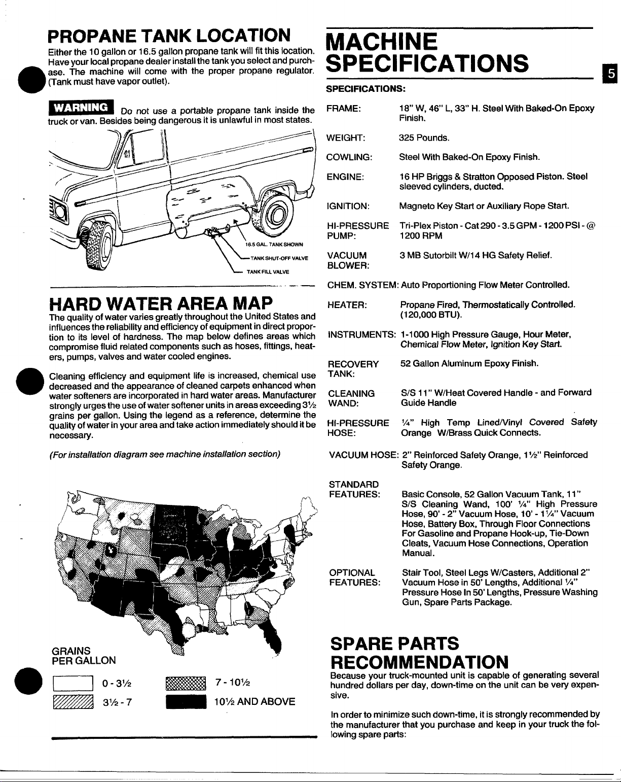
PROPANE TANK LOCATION
Either the 10 gallon or 16.5 gallon propane tank will fit this location.
Have your local propane dealer install
ase. The machine will come with the proper propane regulator.
(Tank must have vapor outlet).
0
the tank you select and purch-
MACHINE
SPECIFICATIONS
SPECIFICATIONS:
E
Do not use a portable propane tank inside the
truck or van. Besides being dangerous it is unlawful in most states.
-.. —
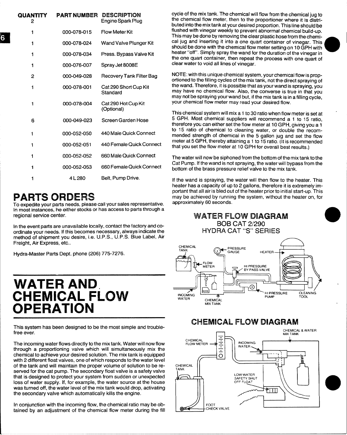
HARD WATER AREA MAP
The quality of water varies greatly throughout the United States and
influences the reliability and efficiency of equipment in direct proportion to its level of hardness. The map below defines areas which
compromise fluid related components such as hoses, fittings, heaters, pumps, valves and water cooled engines.
Cleaning efficiency and equipment life is increased, chemical use
decreased and the appearance of cleaned carpets enhanced when
water softeners are incorporated in hard water areas. Manufacturer
strongly urges the use of water softener units in areas exceeding 3%
grains per
quality ofwater inyour area and take action immediately should it be
necessary.
gallon. Using the legend as a reference, determine the
FRAME:
WEIGHT: 325 Pounds.
COWLING: Steel With Baked-On Epoxy Finish.
ENGINE:
IGNITION:
HI-PRESSURE Tri-Plex Piston - Cat 290- 3.5GPM -1200 PSI-@
PUMP:
VACUUM
BLOWER:
CHEM. SYSTEM: Auto Proportioning Flow Meter Controlled.
HEATER: Propane Fired, Thermostatically Controlled.
INSTRUMENTS: 1-1000 High Pressure Gauge, Hour Meter,
RECOVERY
TANK:
CLEANING
WAND:
HI-PRESSURE ‘A”
HOSE:
18“ W, 46’ L, 33’ H. Steel With Baked-On Epoxy
Finish.
16 HP Briggs & Stratton Opposed Pk3crn. Steel
sleeved cylinders, ducted.
Magneto Key Start or Auxiliary Rope Start
1200 RPM
3 MB Sutorbilt W/l 4 HG Safety Relief.
(120,000 BTU).
Chemical Flow Meter, Ignition Key Start.
52 Gallon Aluminum Epoxy Finish.
S1S 11” W/Heat Covered Handle - and Forward
Guide Handle
High Temp LinedlVinyl Covered Safety
Orange W/Brass Quick Connects.
(For installation diagram see machine installation section)
—..
PE-R--GALLON
,,.
u 0-31’2 E%E$%i37-’0”2
Izzzn “/2-7 - ‘01’2ANDAB0vE
VACUUM HOSE: 2“ Reinforced Safety Orange, 1%“ Reinforced
Safety Orange.
STANDARD
FEATURES:
OPTIONAL
FEATURES: Vacuum Hose in 50’ Lengths, Additional
Basic Console, 52 Gallon Vacuum Tank, 11”
S/S Cleaning Wand, 100’ lA” High Pressure
Hose, 90-2’ Vacuum Hose, 10’-1 l/.” Vacuum
Hose, Batte~ Box, Through Floor Connections
For Gasoline and Propane Hook-up, Tie-Down
Cleats, Vacuum Hose Connections, Operation
Manual.
Stair Tool, Steel Legs W/Casters, Additional 2’
Pressure
Gun, Spare Parts Package.
Hose In 50 Lengths, Pressure Washing
1/4”
SPARE PARTS
RECOMMENDATION
Because your truck-mounted unit is capable of generating several
hundred dollars per day, down-time on the unit can be very expensive.
In order to minimize such down-time, it is strongly recommended by
the manufacturer that you purchase and keep in your truck the following spare parts:
Page 7
CWANTITY
2
1
1
1
1
2
1
1
6
1
1
PAFIT NLMBER’i
000-0?8-015
000-07’$-024
000-078-034’
000-076-007’
000-049-028
000-078-001
000-078-004
000-049-023
000-052-050
000-052-051
DESGR!PT!OM
Engine Spark Plug
Flow Meter Kit
Wand Valve Plunger Kit
Press. Bypass Valve Kit
Spray Jet 800BE
Recovery Tank Filter Bag
Cat 290 Short Cup Kit
Standard
Cat 290 Hot Cup Kit
(Clpticmal)
Screen Gard@nHose
44o Male Quick Connect
440 Female Quick Connect
cycle of the mix tank. The chemical will flow from the chwrrical jug to
the chemical flow meter, then to the proportuonerwhere it is cWatributed intothe mix tank at your desired propo~lon. This line ~h~u~db~
flushed with vinegar weekly to prevent abnormal chemical build-up.
This may be done by removing the clear plastic hose from the c!wm+
cal jug and inserting it into
should be done with the chemical flow meter sisttirq on 10 GPl+ with
heater “off’. Simply spray the wand for the duration of the vinegar in
the one quart cantainer, then repeat the process
clear water to void all lines of vinegar.
NOTE: with this unique chemical system, your chemical flow is proportionedtothe filling cycles of the mix tank, nottha direct spraying af
the wand. Therefore, itispossible that as your wand is spraying, you
may have no chemical flow. Also, the converse is true in that you
may not be spraying your wand but, if the mix tank is ina fillingcycle,
your chemical flow meter may read your desired flow.
This chemical system will mix a 1to30 ratio when flow meter isset at “
5 GPH. Most chemical suppliers will recommend a 1 to 15 ratio,
therefore you can either set the flow meter at 10 GPH, giving you a 1
to 15 ratio of chemical to cleaning water, or double the recomm-
ended strength of chemical in the 5 gallon jug and set the flow
meter at 5 GPH, thereby attaining a 1to 15 ratio. (It is recommended
that you set the flow meter at 10 GPH for overall best results.)
a one quart container of vinegar. This
a
with one quart af
1
1
1
PARTS
To expoditrayour
In most instances, he either stocks or has access to parts through a
regional service center.
[nthe event parts are unavailable locally, contact the factoy and co-
ordinate your needs. Ifthis becomes necessary, always indicate the
method of shipment you desire, i.e. U.P.S., U.P.S. Blue Label, Air
Freight, Air Express, etc..
Hydra-fwfaster Parts Dept. phone (206) 775-7276.
MJO-052-052
000-052-053
4 L 280
ORDERS
parts newts, please call your sales representative.
660 Male Quick Connect
660 Female Quick Connect
Belt, Pump Drive.
WATER AMID
ICHEMICAL FLOW
OPERATIONI
The water will now be siphoned from the bottom of the mixtank to the
Cat Pump. If the wand is not spraying, the water will bypass from the
bottom of the brass pressure relief
If the wand is spraying, the water will then flow to the heater. This
heater has a capacity of up to 2 gallons, therefore it isextremely important that all air is bled out of the heater prior to initial start-up. This
may be achieved by running the system, without the beater on, for
approximately 60 seconds.
valve tothe mix tank.
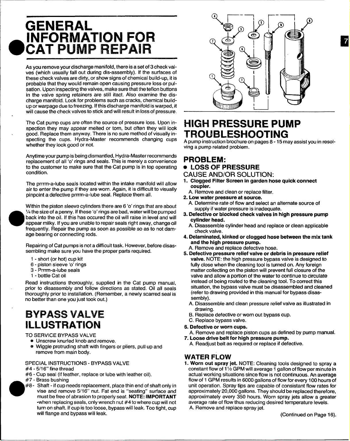
WATER FLOW DIAGRAM
BOB
CAT 2/290
WDRA CAT “S” SEFMES
CHEMICAL
TANK
& ‘;:
MIXTANK
PRESSURE
GAUGE HEATER
~
+
This systam has been designed to be the most simple and trouble-
frwe ever.
This incoming water flows directly tothe mix tank. Water will nowflow
through a pmpcwtioning valve which will simultaneously mix the
chemical to achiew your desired solution. The mix tank isequipped
with 2 different float valves, one of which responds to the water level
af the tank and will maintain the proper volume of solution to be re-
swwed for the cat pump. The secondary float valve is a safety valve
that is desigmsd to protect your system from sudden or unexpected
loss of water supply. if, for example, the water source at the house
was turned off, the water level of the mix tank would drop, activating
the secondary valve which automatically kills the engine.
[n conjunction with the incoming
tained by an adjustment crfthe chemical flow meter during the fill
flow, the chemical ratio maybe ob-
CHEMICAL FLOW DIAGRAM
v
CHEMICAL
FLOWMETER d
-IEMICAL
lNK
r - -K,
{~
1
v 7
.=
.
—
v
z
INCOMING
WATER
LOWWATER
SAFETYSHUT
OFF FLOAT
/-’---
t
CHEMICAL& WI%TE17
MIXTANK
&
I
.
Page 8
As you remove your discharge manifold, there isa set of 3 check valves (which usually fall out during dis-assembly). If the surfaces of
these check valves are dirty, or show signs of chemical build-up, it is
probable that they would remain open causing pressure loss or pul-
sation. Upon inspecting the valves, make sure that the teflon buttons
in the valve spring retainers are still itact. Also examine the discharge manifold. Look for problems such as cracks, chemical buildup or warpage due to freezing. Ifthis discharge manifold iswarped, it
will cause the check valves to stick and will result in lossofpressure.
The Cat pump cups are often the source of pressure loss. Upon inspection they may appear melted or torn, but often they will look
good. Replace them anyway. There is no sure method ofvisually in-
specting the cups. Hydra-Master recommends changing cups
whether they look good or not.
Anytime your’pump is being dismantled, Hydra-Master recommends
replacement of all ‘o’ rings and seals. This is merely a convenience
to the customer to make sure that the Cat pump is in top operating
condition.
The prrrm-a-lube seals located within the intake manifold will allow
air to enter the pump if they are worn. Again, it is difficult to visually
pinpoint a defective prrrm-a-lube seal. Replace them all.
Within the piston sleeve cylinders there are 6 ‘o’ rings that are about
‘/4 the size of a penny. If these ‘o’ ringsare bad, water will be pumped
back into the oil. If this has occured the oil will raise in level and will
appear milky. If you are unable to repair seals rightaway, change oil
e
frequently. Repair the pump as soon as possible so as to not dam-
age bearing or connecting rods.
Repairing of Cat pumps isnota difficulttask. However, before disassembling make sure you have the proper parts required.
1- short (or hot) cup kit
6- piston sleeve ‘o’ rings
3- Prrrm-a-lube seals
1- bottle Cat oil
Read instructions thoroughly, supplied in the Cat pump manual,
prior to disassembly and follow directions as stated. Oil all seals
thoroughly prior to installation. (Remember, a newly scarred seal is
no better than one you just took out.)
BYPASS VALVE
ILLUSTRATION
TO SERVICE BYPASS VALVE
@ Unscrew knurled knob and remove.
@ Wiggle protruding shaft with fingers or pliers, pull up and
remove from main body.
SPECIAL INSTRUCTIONS - BYPASS VALVE
#4 - 5/16“ fine thread
#6 - CUD seal {ifleather, redate or lube with leather oil).
#7 - Brass bushing
#8- Shaft - if cup needs replacement, place thin end of shaft only in
a
vise and remove 5/1 6“ nut. Fat end is “seating” surface and
must be free of abrasion to mo~erlv seat. NOTE: lMPORTANT
-when replacing seals, only”wrenc~ nut #4to where cup will not
turn on shaft. Ifcup is too loose, bypass will leak. Too tight, cup
will flange and bypass will leak.
HIGH PRESSURE PUMP
TROUBLESHOOTING
A pump instruction brochure on pages 8-15 may assist you in resolving a pump related problem.
Plmmmvl:
o LOSS OF PRESSURE
CAUSE AND/OR SOLUTION:
1. Clogged Filter Screen in garden hose quick connect
coupler.
A. Remove and clean or replace filter.
2. Low water pressure at source.
A. Determine rate of flow and select an alternate source of
supply if water pressure is inadequate.
3. Defective or blocked check valves in high pressure pump
cylinder head.
A. Ok-assemble cylinder head and replace or clean applicable
check valve.
4. Delaminated, kinked or clogged hose between the mix tank
and the high pressure pump.
A. Remove and replace defective hose.
5. Defective pressure relief valve or debris in pressure relief
valve. NOTE: the high pressure bypass valve is designed to
fully close when the cleaning tool is turned on. Any foreign
matter collecting on the piston will prevent full closure of the
valve and allow a potilon of the water to continue to circulate
instead of being routed to the cleaning tool. To correct this
situation, the bypass valve must be disassembled and cleaned
(refer to drawing provided in this manual for bypass disassembly).
A. Disassemble and clean pressure relief valve as illustrated in
drawing.
B. Replace defective or worn out bypass cup.
C. Replace bypass valve.
6. Defective or worn cups.
A. Remove and replace piston cups as defined by pump manual.
7’.Loose drive belt for high pressure pump.
A. Readjust belt as required or replace if defective.
WATER FLOW
1. Worn out spray jet. NOTE: Cleaning tools designed to spray a
constant flow of 1‘/2GPM will average 1 gallon of flow per minute in
actual working situations since flow is not continuous. An average
flow of 1 GPM results in 6000 gallons of flow for every 100 hours of
unit operation. Spray tips are capable of consistent flow rates for
approximately 20,000 gallons. They should be replaced therefore,
approximately every 350 hours. Worn spray jets allow a greater
average rate of flow thus reducing desired temperature levels.
A. Remove and replace spray jet.
(Continued on Page 16).
Page 9
OPERATING INSTRUCTIONS
CAUTION: CAT PUMPS
a properly designed pressure reltef mechanism MUST’be installed in
the discharge piping. Failure to install
result in personal injury or damage to the pump or system. Cat
Pumps Corporation does not assume arty liability or responsibility
for the operation of a customer’s high pressure system.
SPECIFICATIONS
vdurrme ...........................................................................................................................3.5 Gf?M
lMdmarfJcr Pressur@......................................................................................................1200 PSI
#~m#num Ink$t Press ure ............................................................... .... .... . .......... -8.5 to + 40
.............................................................................................................................
................................................................................ ..... ..... .... ..... ......... ........ ................O.78O''
B’occr
Stroke .................................................................................... . ........ ..... .... . .... ..... .... .... ........O.472''
Crankcase Capacity ..........................................................................................................10 oz.
Maximum Fluid Tmpmtlm
Inlet Port (l) ............................" ................................................................... . ........ ......... 1/2” N
LNschargaPcwt
I%dky MQunting ........................................................................ .... ..... .... ................... Eit her Side
Shaft fJimmrt@r
Wtright ............................................................................................................................
.........................................................................................................3/8'' N
(2)
..................................................................................................................O.65O''
..........................................................................................1
Dim@n$iQn$.......................................................................................................10.6X 9.1 X 5.7”
U.S. Measuro
PSI
1200 RPM
k30”F
12.1 tbs.
PT
PT
Model 290
are positive displacement pumps. Therefore,
such relief mechanism could
Metric Measure
(-0.6 to+ !2!8::;;;
(268 x 230x 146mm)
[13 L./M)
(1200 RPM)
(20mm)
(12mm)
(0.3 L)
(71“c)
(1/2” NPT)
(3/8” NPT)
Side)
(Either
(l~5\mk~]
CAT IPUMP
This Cat Pump ($’prackt”) is warranted by the manufacturer to be
Moe from dttrf~ctsin
dat@of rmmufactumr’s
ing or ropltmhr~ products which manufacturer’s investigation
Mrcmrawara ddmtiv~ at the time of shipment by the manufacture.
AIUproducts sub@ to this warranty
Pumps
tkm,impairor raplacament.
Tim express
tkm, exprcmsor
d merdrmatrahility or
wwrarotle%+
turm’. Repsrtr cmI’E@WMIWtnt Qf defectiw products as provided
Corp., M mmnwpdis,Mhmeaota 55430, tJ.S.A. for axamina.
warranty set fcwthhwwin is IFIlhw of all other warren.
are Iwwekwdisclaitmatf and exc!uded by the mamdac-
la the501@ 8rIud exclusive remmty providad hereunder and tha
abwm
mmnufactumr shall mrt be liable for any further loss, dama ea or
tmfmnwwi, irmc!udim’u$Incktwrtal m consequential damages, d rectly
or irrdlrectly arisiq Irm the
Thla warranty it?
Products df3$Cr(b@dhereon are covered by one or more of the follo’w,og U S Patems 3558244 3652188 3809508 3920356 and 3930 T56
~Hq&g&”
,,!,f+,.,~f{.., ,,, >
BOX 885 MW4NEAPOLK. MN 55440
P O
Phone (612) 7805440 m Telex 290276
N V CAT PUMPS INTERNATIONAL SA
0.2000 Antwerp Belwum
workmanship and matr3rial for one year from
sh@’rmwTl. This warranty is I!mifed to repair-
/
hrmplid,hclmfhg without limitation any warranties
fitness for a particular purpose and all such
shall be retumad F.0.k%Cat
7
aub@ct tothe following warranty condition
.
Harmonteslraal 29
sale m trae o~ this product.
CH 6300. ZUG Switzerland
CAT PUMPS DEUTSCHLANO GmbH
Restocker Strasse 9
6200 Wlesbaden.Blersladl
CAT PUMPS (U K ) LTO
17A K,ngs RoaIY Fleet
Hampsh, re GU13 9AA
LorelohOhe 5
e
west Germany
e
England
WARRANTY
LUaFIICATION
Pump 011 or equivalent SAE 40 weight hydraulic 011with antlwear and rust Inhibitor ad.
dttives. Change mltml fill after 50 hour run.m parmd, Chwage O(I %V%Wibrme months or at
S00 hour lflterWdS thereafter. Prrrrrm.a-lube seals need no Iubrlcatton. Blu% dot WX3113and
wicks mu$t r9C91v9 three drops of Cat Pump 011 per wick every 54 hour8 of operation.
GOOD
PREVENTATIVE MAINTENANCE.
IIPMmd PRESSURE
Pressure relkef valve must be [nstalled,
DO NOT PUMPACIDS OR AL!RASIVEFUJIOS wdh this unit Consult Cat Pumps km addl.
tlonal #nf0rr17at10n on questionable flulds.
FREEZING CONDITIONS - Pump must be protectect 1rom iroez!ng cond!l
,.
IMPORTANT t2C)NKNTlCJNS
crankcase to dot on o(I gauge window per specifications with Cat
- fill
LUBRICATION IS WE EASIEST, MOST EFFfC!ENT AND LEAST EXPW4SWE OF
Pump oper@#o” must be wlthm RPM and pmasure specttlcat(ons
-
USE OF OTHER THAN CAT PUMP PARTSOr?
THEIR EQUIVALENT VOIOS THE WAWIAMIT
Ions.
Page 10
3/8’
1
\
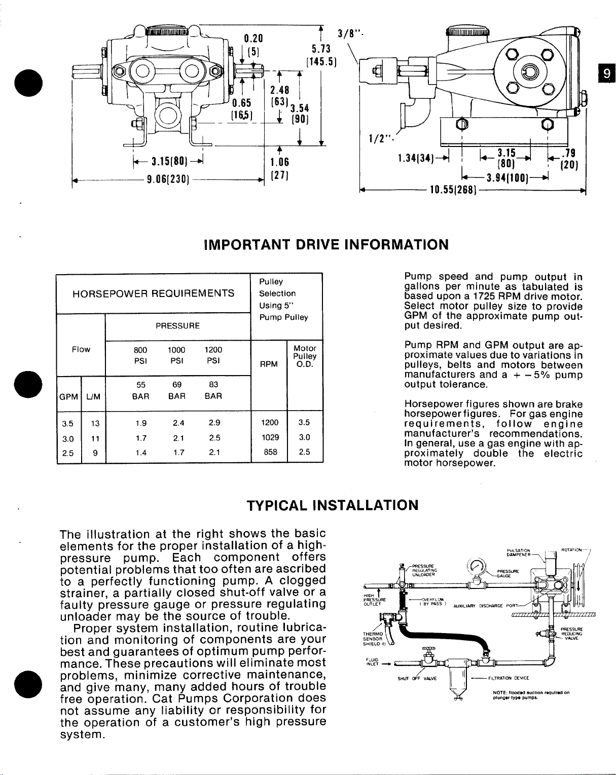
HORSEPOWER REQUIREMENTS
PRESSURE
Flow
LIM
;PM
3.5 13
3.0 11
2.5 9
800
Psl Psl
55
BAR
1.9 2.4
1.7
1.4
1000
69
BAR
2.1
1.7
1/2”-’
1.34[34]4 ! L- ~ap
IMPORTANT DRIVE INFORMATION
Pump speed and pump output in
gallons per minute as tabulated is
based upon a 1725 RPM drive motor.
Select motor pulley size to provide
GPfvl of the approximate pump output desired.
Pump RPM and GPM output are approximate values due to variations in
pulleys, belts and motors between
manufacturers and a + –
output tolerance.
Horsepower figures
horsepower figures. For gas engine
requirements,
manufacturer’s recommendations.
In general, use a gas engine with approximately double the electric
motor horsepower.
1200
Psl
83
BAR
2.9
2.5
2.1 858
Pulley
Selection
Using 5“
Pump Pulley
tblotor
RPM .
1200
1029
P; I&y
3.5
3.0
2,5
I
I
I
I
.79
k(20)
5°/0 pump
shown are brake
follow engine
TYPICAL INSTALLATION
The illustration at the right shows the basic
elements for the proper installation of a high-
-pressure pump. Each component offers
potential problems that too often are ascribed
to a perfectly functioning pump. A clogged
strainer, a partially closed shut-off valve or a
faulty pressure gauge or pressure regulating
unloader may be the source of trouble.
Proper system installation, routine lubrica-
tion and monitoring of components are your
best and guarantees of optimum pump perfor-
mance. These precautions will eliminate most
problems, minimize corrective maintenance,
a
and give many, many added hours of trouble
free operation. Cat Pumps Corporation does
not assume any liability or responsibility for
the operation of a customer’s high pressure
system.
Page 11
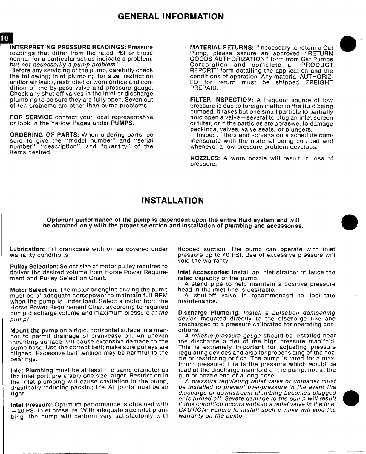
GENERAL IINFORMATIC)N
~
It
p
INTERPRETING PRESSURE READINGS: Pressure
readings that differ from the rated IISl or those
normal far a
buf not necessarily a pump probkem!
Ehefore any servicing of the pump, carefully check
the following; inlet plumbing for size, restriction
andlor air leaks, restricted or worn orifice and condition of the by-pass valve and pressure gauge.
Ch@ck any shut-off valves in the inlet or discharge
plumbing to be sure they are fully open. Seven out
of ten problems are other than pump problems!
FOR SERVICE contact your local representative
cw look in the Yellow Pages under PUMPS.
ORDERING OF PARTS: When ordering parts, be
sure to give the
number”,
items desired.
particular set-up indicate a problem,
“model number” and “serial
“description”, and “quantity” of the
MATERIAL RETURNS: If necessary to return a Cat
Pump, please secure an approved “RETLfRN
GOODS AUTHORIZATION” form
from Cat Purnrm
Corporation and complete a “PRODUCT
REPORT” form detailing the application and th~
conditions of operation. Any material AIJTHQRIZED for return must be shipped FREIGHT
PREPAID.
FILTER INSPECTION: A frequent source of low
pressure is due to foreign matter in the fluid being
pumped. It takes but one small particle to partially
hold open a valve—
or filter, or if the particles are
several to plug an inlet screen
abrasive,to damage
packings, valves, valve seats, or plungers.
Inspect filters and screens on a schedule comm-
ensurate with the material being pumped and
whenever a low pressure problem develops.
NOZZLES: A worn nozzle will result in loss of
pressure.
a
INSTALLATION
Optimum ptwfomantm at tfw pump is dependent upon ths entire fluid system and will
obtained only with NM?properselection and installation of plumb!ngand acmassories.
be
Lubrication: Fill crankcase with oil as covered under
warranty conditions.
PIuil@y $elactitm: Select size of motor pulley required to
deliver the desired volume from Horse Power Require-
ment and Pulley Selection Chart.
Wutar Sel@cticm: The motor or engine driving the pump
must be of adequate horsepower to maintain full RPM
when the
Horse Power Requirement Chart according to required
pIJrYIP discharge volume and maximum pressure at tfre
pump!
MourIt tl’m pump cm a rigid, horizontal suface in a
ner to permit drainage of crankcase oil.
mounting surface will cause extensive damage to the
pump base. Use the correct belt; make sure pulleys are
aligned. Excessive belt tension may be harmful to the
bearings.
Inlat Plumbing must be at least the same diameter as
the inlet port, preferably one size larger. Restriction in
the inlet plumbing will
di”autically reducing packing life. All joints must be air
tight.
Inhat
+ 20 PSI inlet. pressure. With adequate size inlet plum-
bing, the pump will perform very satisfactorily with
pump is under load. Select a motor from the
man-
An uneven
cause cavitation in the pump,
Prmwwm%x Optimum performance is obtained with
flooded suction. The pump can operate with inlet
pressure up to 40 PSI. Use of excessive pressure will
void the warranty.
Inlet Accessories: Install an inlet strainer of twice the
rated capacity of the pump.
A stand pipe to help maintain a positive pressure
head in the inlet line is desirable.
A shut-off valve is recommended to facilitate
maintenance.
Discharge Plumbing: Install a puisatian dampening
device mounted directly to the discharge line and
precharged to a pressure calibrated for operating con-
ditions.
A re/iab/e pressure gauge should be installed near
the discharge outlet of the high pressure manifold.
This is extremely important for adjusting pressure
regulating devices and also for proper sizing of the noz-
zle or restricting orifice. The pump is rated for a
max-
imum pressure; this is the pressure which would be
read at the discharge manifold of the pump, not at the
gun or nozzle end of a long hose.
A pressure regulating relief valve or unloader must
be installed to prevent over-pressure in the event the
discharge or downstream plumbing becomes plugged
or is turned off. Severe damage to the pump wif[ result
if this condition occurs without a rslief valve in the line.
CA UTIOIV: Failure to install such a valve wtil void the
warranty on the pump.
@
a
Page 12
I
—
58
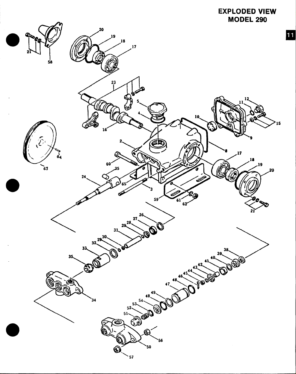
EXPLODED VIEW
MODEL 290
20
❑
17
’15
‘ 57
Page 13

ITEM
PARTS LIST
CAT PUMP MODEL 290
2
3
4
5
8
9
10
11
12
15
16
17
18
19
2’0
21
23
24
25
26
X
2!2
3’0
31
32
33
34
35
PART No
28766
856W)
14177
43211
26(M37
26105
22289
23170
25625
%2520
43804
14487
24159
26536
27950
92519
101799
101‘Boo
16948
20017
25301
25327
25392
28771
29003
29614
26854
28597
25128
25635
30315
30325
Dmclllm’lc)l’i!
QTY.
Crankcase
Stud (M8 x 82)
Cl-Ring, Oil Filler Cap
Oil Filler Cap
O-Ring, Crarrkcase Cover
Crankcase Cover
Oil Gauge
O-Ring, Drain Plug
Drain Plug
Sems Comb l-lead
Screw (IM6 x 20)
Crankshaft
Rearing
Oil Seal
Q. Ring, Oil Seal Case
Oil Seal Case
Semrs
Comb. Head
Screw (M6 x 16)
Confecting Rod
Piston Rod
Piston Pin
Seal Washer
Oil Sea!
Harrier Slinger
O-Ring, Sleeve
O-Rina, Sleeve (Viton)
Back-U”p Ring, Sleeve
Sleeve (29743 Lfnchrorned) 3
Seal Washer
Seal Retainer 3
Inlet Manifold
Inlet Manifold-Stainless
Steel
Prrrrrm-A-Lube Seal
Prrrrrm-A-Lube Seal(Viton) 3
PART NO.
ITEM
3a
;
1
39
40
27004
30543
30544
1
1
1
1
1
1
41
42
43
44
45
46
6
1
47
4a
2
2
2
49
50
2
43172
27983
27002
27006
18956
14158
101802
23172
11377
21985
24459
25634
DESCFUPTIC)N
Inlet Valve
f3ac-Cup Piston
Bat-Cup Ring
(Teflon)
Cup (Viton}
Piston Spacer
Piston Retairw
Conical Washer-SS (M6)
Nut-SS (M6)
Cotterpin
Cylinder (43834 Unch)
O-Ring, Cylinder
O-Ring, Cylinder (Viton]
Bat-Up Ring, Cylinder
Discharge Manifold
Discharge Manifold-
3
3
3
3
3’
3
3
3
3
6
6
3
1
Stainless Steel
8
3
3
3
3
3
3
3
3
51
52
53
54
56
57
58
59
60
3
61
3
62
1
63
64
43442
43360
43723
43434
81109
101804
25130
26246
30901
30920
30910
30032
30047
Valve Spring Retainer
Valve Spring
Valve
Discharge Valve
Seat
Hex Nut (MS)
Hex Flange Nut (M8)
Shaft Protector
Angle Rail
Hex Cao Screw
1
(5/16 x23A)
Split Lockwasher
(5116 US)
I’-lex Nu~ (5/16 LfS)~
Pulley 5“ w{2
Set screws
Key (M5)
J
30612
Mk,ng
30246
Pulley
Asbly
;
3
3
3
2
2
;
2
a
2
2
1
1
:
30023
3
6
3
1
1
3’0305
3
3
2
1
30431
3
3
3
i
1
Cup Kit
cup
O-Ring, Cylinder
Cotterpin
Instruction Sheet
Cup Inserter
Seal Kit
Prrrrrm-A-Lube Seal
Cotterpin
Abrasive Paper
Instruction Sheet
Slt?eve
and Seal Kit
Prrrrrm-A-Lube Seal
Barrier Slinger
Cotterpin
Sleeve
O-Ring, Sleeve
instruction Shee’
SERVICE KITS
30686
3
3
3
3
3
1
30860
6
3
:
3
Vahm Kit
Valve Spring Retainer
Valve Spring
Valve
Valve Seat
O-Ring, Cylinder
Instruction Sheet
Piston Kit
O-Ring, Cylinder
Back-Up Ring, Cylinder
Bat-Cup Piston
i3ac-Cup Ring
cup
Piston Spacer
3
Piston Retain@r
3
3
Conical Washer (M6)
Nut (!v16)
3
3
Cotterpin
Inlet Valves
3
1
Instruction Shr3e!
Page 14

SERVICING DISCHARGE VALVES
& VALVE SEATS
e%
DISASSEMBLY
1.
Loosen the 2 (M8) locking nuts approximately one
turn.
2.
Then remove the 2 (M8) flange nuts.
3.
Grasp the discharge manifold with 3 fingers on
the underside and tap with a soft mallet to remove
Valve assemblies will remain with the manifold. in-
4.
vert manifold and discharge valve assemblies
should fall out.
Inspect discharge valves for wear or ridges.
5.
(Sperical valves due to their shape must be replac-
ed when worn.)
REASSEMBLY:
1.
Place retainer in manifold chamber.
2.
Next insert spring into center of retainer
3.
Place valve over spring with spherical (mooned)
side down.
4.
Next insert the valve seat.
Position manifold back onto pump. NOTE: Exer-
5.
cise caution when inserting cylinders into manifold
to avoid damaging cylinder o-rings.
Replace flange nuts on studs and hand tighten
6.
both sides. Then torque each side to
pounds.
Hand tighten locking nut.
7.
CAUTION: When restarting the pump, check to see
that there is no cy/inder motion as this will
cause premature failure of the cylinder o-rings.
Center cy/inder motion canbe eliminated by switching with one of the endcylinders,
125 inch
SERVICING THE PUMPING SECTION
DISASSEMBLY:
1.
Remove discharge manifold as described above.
2.
Slip cylinders out of inlet manifold.
NOTE: Identify cylinders so they will be re/apced in
their origional position. (Front to back)
3.
Remove cotterpin, nut, and washer.
4.
Next remove piston retainer, spacer, and piston
assembly.
Remove inlet valve.
5.
Page 15
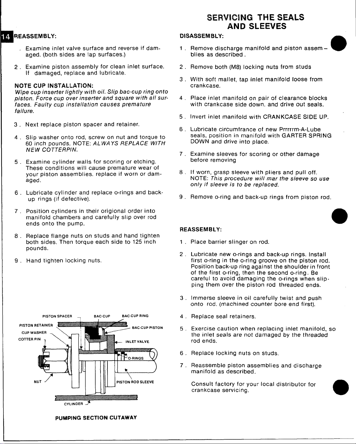
A WEASSEMBLY:
m
Exarnirm inlet valve surface and reverse if damaged. {both sides are lap surf aces.)
Examine piston assembly for clean inlet surface.
2.
If damag~d, replace and lubricate.
lWITE CUP INW”M.LAT[QN:
Wipe cup Inswfer Iight/y with oii. Slip Me-cup ring onto
pisfon. Force cup over inserter and square with all sur-
faces. Faulty cup installation causes premature
fa)lure.
Next replace piston spacer and retainer.
3.
4.
Slip washer onto rod, screw on nut and torque to
60 inch pounds. NOTE: ALWAYS REPLACE WITH
NEW CQT7ERPIN.
5.
Examine cylinder walls for scoring or etching.
These conditions will cause premature wear of
your piston assemblies. replace if worn or dam-
aged.
6.
Lubricate cylinder and replace o-rings and back-
up rings (if defective).
SERVICING THE SEALS
AND SLEEVES
DISASSEMBLY:
Remove discharge manifold and piston a.sst?m -
1.
blies as describ~d .
Remove both (M8) locking nuts from studs
2.
With soft ma[let, tap inlet manifcdd lcms@ from
3.
crankcase.
Place inlet manifold on pair of clearance Mocks
4.
with crankcase side down. and drive out seals.
Invert inlet manifold with CRANKCASE SIDE UP.
5.
Lubricate circumfrance of new Prrmrrn-A-Lube
6.
seals, position in manifold with GARTER SPRING
DOWN and drive into place.
Examine sleeves for scoring or other damage
7.
before removing
If worn, grasp sleeve with pliers
8.
NOTE: This procedure will mar the s[et?ve so LJiW
only it sleeve is to be replaced,
Remove o-ring and back-up rings from piston rod.
9.
and pull off.
a
7.
Position cylinders in their origional order into
manifold chambers and carefully slip over rod
ends onto the pump.
Replace flange nuts on studs and hand tighten
%.
both sides. Then torque each side to 125 inch
pounds.
Hand tighten locking nuts.
9.
PISTON SPACER . . EIAC.CUP
coTTER”N1 \Y
BAC.CUP RING
+--- INLET VALVE
IliE--4l
REASSEMBLY:
Place barrier slinger on rod.
1
2
Lubricate new o-rings and back-up rings. Install
first o-ring in the o-ring groove on the piston rod.
Position back-up ring against the shoulder in front
of the first o-ring, then the second o-ring. lilt?
careful to avoid damaging the o-rings whtan slip-
ping them over the piston rod threaded ends.
Immerse sleeve in oil carefully twist and push
3
onto rod. (machined counter bore end first].
Replace seal retainers.
4
Exercise caution when replacing inlet manifold, so
5
the inlet seals are not damaged by the threaded
rod ends.
Replace locking nuts on studs.
6
Reassemble piston assemblies and discharge
7
manifold as described.
CYLINDER ~
PUMPING SEGTION CUTAWAY
Consult factory for your local distributor for
crankcase servicing.
a
Page 16

●
DIAGNOSIS AND MAINTENANCE
PROBLEM
Pulsation Faulty PulsationDampener Check Precharge
Pressure
Low
Wmps runs axtremely rough,
wessure very low
:yfinder O.rings blown nexf to
iacharge manifold
Warped manifold
eakage atthe cylinder O.rings Loose cyl!nders. Cylinder motion
t fhe discharge manifold and
lack, powdery substanca in fhe discharge manifold
rea of the O.rings
later leakage from under the Worn Inlet manifold seala. Leaking Installaeals If piston rodsleevea prescored,
det manifold
ii leak between crankcase
nd pumping section
il leaking in the area of
rankahaft
cau5ed by improper shrmming of the
sIeeve O-ring
Worn crankcase piston rod seals
Excess 011 from wicks
Worn crankshaft seal or Improperly
Installed oil seal retainer packing gasket andlor seala
Bad bearing
PROBABLECAUSE
new one
Worn nozzle Replace nozzle, of proper alze May be caused by humid ah Change oIl at 3 month or 500 hour intervals
Belt Sllppage
Alrleakir inlet plumbing
Pressuregaugeinoperativeor not Check
registering accurately
Relief valvestuck, partiallypluggedor
Improperlyadjusted;valve seat worn
Inlet suctionstrainerclogged or
Impropersize
Worn p]ston assembly Abrasivesin
pumped fluid or severe cavitation. must be Iimited to lifting less than 20 feet of
Inadequate water supply. water or -8.5 PSI vacuum.
Fouled or dirty inlet or discharge Clean inlet and discharge valve assemblies.
valves
Worn Inlet or discharge valves
Leaky discharge hose
Restricted !nlet or air entering the inlet
plumbing
Inlet restnctionsa ndlorair leaks. Replace worn cup or cups, clean out foreign
Damaged cup or stuck inlet or
discharge valve
Worn Inlet manifold seala Replace worn seals.
Worn Inlet seals allow pump to draw Install new inlat manifold seals.
air.
Preaaures In excesaof rated PSI Check for plugged nozzle, closed valves or
Tighten or replace; use correct belt
Disassemble,reseal, andreassemflle
with new gaugq replace worn or
damaged gauge, P.N. 06090 Oil leaking from underside of Worn crankcase piston rod seals
Clean, andadjusl reliefvalve;check for worn
and dirtyvalveseata. KitAvailable. Damagedor improperlyinstalledod
Clean. Useadquatesize. Checkmore frequently.
Install proper falter. Suction at inlet manifold
Replace worn valves, valve seats andlor
discharge hose.
Proper size inlet plumbing; check for air tight
seal
material, replace worn valves
—
!mproperly adjusted bypass valve Chrome plating of cylinders damaged
Replace manifold
Remove spacer shims on manifold studs. Do not Strong surging at the inlet and
remove too many shims orthe ears of the
manifold will be bowed when the manifold is side discharge valves
retightened, causing looseness in the center
cylinder
replace sleeves and aleeve O.rings.
RePIaCe crankcase piston rod Seak
Reduce quantity of oil per oiling
Remove oil seal retainer and replace damaged
Replace bearing
SOLUTION
if low recharge it or install a
PROBLEM PROBABLECAUSE SOLUTION
Excessiva play in the end of tha
crankshaft pulley
Water in crankcase crankcase oil every month or200houra) P.N. 06100,
Worn main ball bearing from excessive
tension on drive belt
condensing into water inside the
Leakageof manifold inletseals andlm Replace seals,sleeve andO.mgs,
piston rod sleeve O.nng
Replace ball bearing. Properly tenaion belt.
using Cat Pump Crankcase Oil (other approved
crankcase
Replaceoil gaugeor coverO-ring,and drainplu
Oil leakingat tha rear portionof
the crankcase
Oil leakage from drain plug
Loud knocking noise in pump
Frequent or premature failure of
the inlat manifold seals
Shortcup life
low preaaure on
the discharge
gaugeor crankcaaerear coverO.ring,
anddrain plug
Loose drain plug or worn drain plug
O.ring
Pulley Ioose on crankshaft Check key and tighten set screw.
Broken or worn bearing
Scored mds or sleeves
Over preaaure to inlet manifold
Damaged or worn chrome plating of Replace cylinders
the cylinders
Abraswe material mthe fluid being Install proper filtration on pump inlet plumbing
pumped
Excassive pressure andlor
temperature of fluid being pumped
Over pressure of pumps Reduce pressure
Running Pump dry Do not run pump without water
Front edge of piston sharp
causing excessive wear of cups. Maybe compatible with chrome
caused by pumping acid solution.
Foreign particles in the inlet or
discharge valve or worn inlet andlm
O.ring
O-ring
Tighten drain plug or replace O.ring
Replace bearings
Replace rods and sleeves.
Reduce inlet pressure per instructions
Check pressures and fluid inlat temperature; be
Sure they arewithinapecified range
Replace with new piston
Install new cups and cylinders. Pump only fluld
check for smooth lap surfaces on inlet and
discharge valve seats. Discharge valve seats
a nd inlet Valve seats may belapped on a very
fine oil stone; damaged cups and discharge
valves cannot ba lapped but must be replaced.
Page 17

as it passes thrcwgh”thahose. Therefore, it is
necessary to increase the pwwsure at the
machine 40 PSI for eve~ additional 50 feet of
cleaning
solution hos~ over 1100feet.
CHEMICAL PROPORTIONING AND
LEVEL CONTROL ILLUSTRATION
PROI=QRTIONING VALVE REPAIR KIT
Pm
VE
MIX
TANK OVERFL~W$
1. Float ball in mix tank hanging up (not moving frissdy).
2. Extension bracket pinching the float lever, restricting full a@km of
the lever.
3. Plunger not seating properly cmthe vakm. (Remove the 2 screws
which hold the extension assembly to th~ valve. Do not Iasti or
drop thisscrews. Remove the wtmwion assembly. Turn itupsk.ka
down. Inspect the plunger for proper seating. If tl%ra is no
obstructing the vahm or plunger, the plunger maybe nut of adj,ustme.nt. To adjust, loosen thes@ screw on ths ball nut rarncfmow
tho ball toward the end of the rod 1/16“. Retighten set scxww.
Place wtension assembly back into position. Tighten the two
screws.
MIX TANK DOESN’T’ KEEP UP WITH WATER CM$TPWF
1.
Check garden hose quick connect assembly screen.
Check garden hose
2.
kinks or blockage.
3.
Float ball in mix tank hanging up. (Not moving freely).
4.
Extension bracket pinching float lever, restricting full action of
lever.
5.
Valve plunger not o~eninq fullv. To adiust, remmm tlm
which “hold-theextension >sse-mbly to ‘the‘valve. (Do not lose w
drop the screws). Remove the extension assemb[y, turn it upside
down. To adjust, loosen the setscrew on tho bait nut. Place your
thumb on the plunger and pressitin1/16“ and siide the ball nut WI
set screw toward the plunger end 1/16“, Tighhan the s~t screw.
Place the extension assembly back into position. Ifthe tank
to overfill, the ball nut is too c[ose to the valvo plunger and should
be moved back away from the valve plunger slightly.
mdlor feed hose to the mix tank far clog,
ckbris
2 screws
starts
@
iaw
CHEMICAL TANK
TROUBLESHOOTING
WIm LawCHEMICALFmw
1.
Chack that hoses in the tank are secured. Check that the hose
from the top of the flow
with no kinks, Check the hose from ttm bottom ofthe flow meter to
the them. Jug for
2.
ICheck th~ foot valve and
goes into the mix tank. To check Wis screw for proper function,
remove it fmrm the plastic hose. You should ba able to suck
through the hcwmbarb end, but you should
through the hose barb end. (If you
rinso it out with vinegar). When screen is removed the chemical
bsl hose should kmIifkadinto a vertical position so the ball in the
foot valve will seat by gravity. (This isonly a tempora~ fix for low
watfiwfwessuns areas.)
3. Check flmv metcwfor float obstruction.
4. Check ta h’ummethat the adjusting screw on proportioning venturi
is ‘b~cked out.
5. ls proportioning wimturiclmsed? Soak in warm water or vinegar
Soh.ltkm.
& Is incoming waihwpressure lIsss
7. Cracked or defective ch@micalflow meter?
IWITE!: If YOUam in a low water pressure area and find that the volumo of water entering the mixtank is notenough to allow yourventuri
to siphon chemical, unsc~ew the spring
and rwmmmthe
IEMJ3MJW To ADJUST CWWKL5L WITH THE
1,
Debris lodged L@tincfteflon seat inflow meter knob.
2. TIMlcmsaat dismcmnting from flow meter knob.
spring.
mieterto the sid~ of the mix tank issecured
kinks or cracks.
screen on the end of the hose which
not be able to blow
can not suck through it then
than 20 PSI.?
from the foot valve screen
mow METER
PUMP PULSATES WHEN W-METANK [$ IN
1.Check that the hose which goes from the gray plastic venturi to
the bottom of the tank is not directed toward the Cat pump pickup
port. If it is, aim it in another direction.
HEATIN
INFOR
The propane heater incoporatad in this equipment is of special d@sign for use in the carpet cleaning industry. [t’s high pressure coils
and thermostatic temperature control make it simple to operate and
reliable. One@tlw desired temperature is set, the heater’ will then go
‘on’and ‘off according tothe water temperature within the heater. As
water is used through the cleaning tool, cold water entering tlw heater will ati]vate the thermostatically controlled
firing the heater to maintain a consistent fiow of hot water. One@tho
cleaning wand is shut off and the flow of water through the heatfw
stops, the heater will continue to burn until the set tempimatwe is at-
tained.
It ispossible th~n with this design that the flame maybe on when tlm
wand is off, likewise, it is possible the flame may be off when the
wand is on.
~ This beater is desicmed to burn warm mopane
gas only. Any liquid propane entering tke heater may c~use damage
to the control valve on the heater. Itwill also
and a soot build-upon the coils. Therefore, itis necessary to shut off
the heater and close the valve at the tank bfftween cleaning locations. Failure to do this allows sloshing liquid to enter
line to the heater.
G SYSTEM
MATION
A FM. MODE
propane valve thereby
cause improptmburning
t17E3vapor feed
o
W31JJTiClN REVERSlklG FIWWd MM TANK To CHEMICAL JUG
1. Anti-siphon scnwanremoved from chemical jug hose.
2. Debris in anti-siphon wmsen.
Overfilling of the propane tank will
this, advise the attendant filling the tank rmt W fftil We t$snk tmmr
!307.. When filling the tank, watch the 10?6 valve and imm~diately
cause many problems. To avoid
Page 18

stop filling when whke liquid starts spurting from the 107. valve. To
prevent damage to the propane regulator, always close the valve on
the tank before filling.
When venting the heater through the roof of the van, it is necessary
to install a draft diverter on top of the heater. This will prevent down
drafts from blowing out the pilot light.
The propane regulator is pre-set at the factory at 6 oz. of propane.
This reading is taken at the control valve on the heater (see figure A
#6). To prevent road dust and moisture from entering the propane
regulator, keep the white Tupperware cover (supplied) on the regulator at all times.
To avoid restriction of airflowat base of heater, keep articles such as
chemical containers, hose, boxes, etc. from within 18 inches of base
of heater. NOTE: This restricted situation also creates an over rich
condition which results in soot build-up.
IMPORTANT: If a new propane tank has been installed or hoses
have been disconnected, air may enter propane hoses and must be
purged prior to attempting to light the pilot burner. Should this condi-
tion exist, operator must depress the pilot buttonfor 1-5 minutes and
attempt to ignite the pilot light at 15 second intervals. A very slight
hissing noise should be evident while performing this operation.
HEATER - OPERATING
INSTRUCTIONS
Heater must be Wed with water
mm!z!ilpriortoignmg.
A. TO START PILOT:
1. Adjust thermostat control knob on unitrolto ‘normal’. @ Fig. A.
2. Adjust upper dial to ‘pilot’position. @Fig. A.
3. Depress pilot button. @Fig. A.
4. While pilot button is depressed with the left hand, use
your right hand forefinger to depress the electric spark pilot
igniter button several times in rapid succession, then look to
see if pilot is lit. If not, depress in rapid succession again until
lit. If this fails, use the resourceful match.
NOTE: Whenever ignitingpilot, hold litmatch in front of pilotsight
opening before inspection. Move lit match toward pilot
burner. The pilot should ignite.
IF HEATER FAILS TO LIGHT:
Is propane tank full?
Is propane tank valve open?
Has air been properly bled from propane line?
Once pilot is litcontinue depressing button for 10 seconds to
insure thermo coupler has been heated.
B. TO LIGHT MAIN BURNER:
1. Turn upper knob to ‘on’ position. Flame will come on.
IF NOT: Pilot has expired.
Turn upper dial to ‘off position. @Fig. A.
Do not attempt to relight pilot for 60 seconds.
Then repeat instructions A -#1 -4.
Water may already beat controlled temperature.
IF YES: Flame will turn off when thermostat senses maximum temp.
C. TO ACHIEVE PROPER CARPET CLEANING
TEMPERATURE:
1. Complete procedures A & B
2. With 100’ of hose, turn cleaning wand on for 5 minutes and
the temperature should stabilize.
3. Once a constant temperature is established, turn cleaning
wand ‘off. The flame on the heater burner should remain on
for 10-15 seconds.
A. If the flame expires priorto 10 seconds, turn the
thermostat dial to a higher reading, then repeat C 1-3.
B. If the flame remains lit after 15 seconds, turn the
thermostat dial to a lower reading, then repeat C 1-3.
D. W SHUT 12N3WWNHEATER:
1. Turn upper dial to ‘off position. @ Fig. A.
_ 2. Turncleaningwandonfor3 t05min.testo
cool heater core. If heater core is not cooled, it is impossible
that the heat retained in the core will cause boiling back into
the chemical mix tank.
3. Close propane tank valve while
wand is on and heater is cooling.
PILOT BURNER
FIG
ADJUSTMENT
1. Remove pilot adjustment cap@
2. Adjust pilot key to provide
properly sized flame
3. Replace pilot adjustment cap
ALLEN HEAD PIPE PLUG ~
CAN BE REMOVED
FOR MONOMETER INSERTION
TO HEAD PROPANE OUNCES.
o
HEATER
TROUBLESHOOTING
o EXCESSWE HEAT
o FLAMES PROTRUDING OUTSIDE
THE ILOWER OPENINGS
CAUSE ANDOR SOLUTION:
1.
Thermostatic control dial set too high
A. Turn dial to lower setting
2. Maladjustment of propane regulator. NOTE: Propane regulators
are facto~ preset and maybe readjusted by authorized
personnel.
A. Contact manufacturer to determine correct procedure.
B. Have your local propane dealer use a monometer at the
unitroi to re-set the propane regulator to 7 oz. maximum.
3. Overfilled propane tank. NOTE: Propane heater is designed to
operate on vapor propane only. Over-filling a propane tank
allows liquid propane to enter all heater related components
and permits an over-rich burning condition to occur. This
condition usually requires the heater core to be cleaned of soot
and carbon deposits. Cleaning is a messy, dirty job and very
inconvenient, so don’t let it happen to you!
PROBLEM:
● PILOT LIGHT
CAUSE AND/OR SOLUTION:
1. Pilot lightwillnot ignite. NOTE: Do not use a needle or pinto clean
pilot orifice - use compressed air or solvent only.
A. Veri@ propane reaching igriitor. NOTE: A kinked or crushed
hose may impede propane flow.
B. Remove and clean orifice.
C. Verify igniter spark isoperating correctly.
B
Page 19

VACUUM SYSTEM
~lNFORMATIoN
Tlw vacuum Mcwwwincorporated in this machine is a positive dis-
placement
marwmand lifeofthis unit isgreatly dependent on the care and propisrmaintiarnancait mtmives.
lobe type, manufactured byFuller Company. The perfor-
‘VACUUMTANK FILTER BAGS ‘
Hydra-fwlashsrfilter bags are
dirt that would normally
The use ofthese bags, if
the build-up of much ofthe debris inthe tank and
customer’s driveway or street. The drawstring top of thwse bags is
designed to be tied to the incominq dirtv water irrlet in the vacuum
tank.
Tore-order bags use part numbw
designed to trap all c#tfm lint, sand and
collect at the bottom of your vacmmrntank.
emptied at the end of @achjob, will fflimhvata
avoid a moss on th~
-.
049-02$
a
Bacausa of ti’mclose tolerances between the lobes and housing of
the vacuum blower, solid objects entering the inlet will darnage the
internal lobes, gears and bearing or direct drive coupler.
TCIprevent this, a stainless steel filter screen has been placed at the
vacuum inlet inside the vacuum recovery tank. This stainless steel
screen is finger tight and should be removed for cleaning weekly.
~ Should be used when machine is heirm run for
test purposa and the vacuum inlet orI top of machine is op~n.
TCIprotect the vacuum Mower from overloading and damaging itself,
thrwe is a vacuum relief system installed on the vac tank
th~ vacuum tank inlet is completely sealed off, a maximum of 14 HG
wi!l‘b@attained. A hole on the top blower pipe elbow acts as the lubri-
caticm point; atthe end ofeach day, LPS 1orWD-40 issprayed in before shutting down the machine. See blower lubrication illustration. If
you fail to lubricate the vacuum blower daily, rustdeposits and moisture will decrease the life of the vacuum blower.
FMad the vacuum blower manual carefully for proper oil change and
grease application. The maintenance log may differ slightly from the
manual, but the truck-mounted carpet cleaning machine application
is very demanding of the vacuum blower and therefore it should be
maintained more regularly.
lid. When
INCOMING DIRTY
a“”””””
\
/
/
((i
.
VACX.JUM
TANK
WALL
ILTER BAG
BLOWER LUBRICANT
VACUUM FLOW DIAGRAM
VACUUM RECOVERY TANK
1
VACUUM RELIEF
h
S/S FILTER
VN3JLM
BLOWER
EXHAUST
TOXIC FUMES
a:**
00
w
= E’xc
HOSE K) VAC TANK
I
FII-TER BAG
A
A
1
w
SPRAY LUBRICANT INTO VACUUM RELIEF HOLE FOR 3
TO 5 SECONDS, THEN IMMEDIATELY SHUT OFF
MACHINE.
USE ONLY LPS 1 OFI WD-4(1 MOISTURE DISPLACING
LUBRICANTS.
m
Page 20

WARRANTY
o
FULLER
installed, maintained, and operated under normal conditions with competent supervision.
No person, agent, representative or dealer isauthorized togiveany warranties on behalf of FULLER norto assume for
FULLER any other liability in connection with any of FULLER’S products.
This warranty shall extend for one (1) year from date of installation provided this equipment has been put into service
within six months after shipment from the FULLER factory. If repairs or replacements are made by the Purchaser
without FULLER’S prior written consent, FULLER’S warranty shall cease to be in effect. No allowance will be
granted for any repairs or alterations made by the Purchaser without FULLER’S prior written consent.
Machinery, equipment and accessories furnished by FULLER, but manufactured by others, are warranted only to the
extent of the original manufacturer’s warranty to FULLER.
FULLER agrees at its option to repair at the point of shipment or to replace without charge f.o.b.
any part or parts of products
FULLER’S satisfaction to have been defective when shipped, provided the Purchaser promptly notifies FULLER, in
writing, of such alleged defect.
FULLER’S liability to Purchaser, whether in contract or in tort arising out of warranties, representations, instructions,
or defects from any cause shall be limited to repairing or replacing of the defective part or parts as aforesaid, f.o.b.
point of shipment,
No liability whatsoever shall attach to FULLER until said products have been paid for.
EXCEPT’ AS STATED IN THIS SECTION AND IN THE PRECEDING SECTION TITLED “WARRANTY” AND
EXCEPT AS TO TITLE, THERE ARE NO GUARANTEES OR WARRANTIES OF MERCHANTABILITY, FITNESS,
PERFORMANCE OR OTHERWISE, EXPRESS, IMPLIED OR STATUTORY, AND FULLER SHALL HAVE NO
LIABILITY FOR CONSEQUENTIAL, INCIDENTAL OR OTHER DAMAGES, HOWSOEVER CAUSED.
DATE installed ______
MODEL ____
SERIAL #——--–-
warrants products of its manufacture to be free from defects in material and workmanship if properly
point of shipment,
of FULLE R’S manufacture, which within the specified warranty period shall be proved to
FULLER COMPANY
2966 East Victoria Street
Compton, California 90224
a
FACTORY AUTI-ICRL?ED SERVICE CENTERS
FOR SLJTOF?BILT PRODUCTS
FULLER COMPANY / COMPTON DIVISION
2966 E. VICTORIA ST., COMPTON, CAL. 90224
BAYLISS IMACHINE & WELDING CO.
ASSOCIATED TECHNICAL SERVICES, INC.
2131636-9821 or 639-7’600
2901 8TH AVENUE NORTH
BIRMINGHAM, ALABAMA 35203
BARNEY’S PUMPS INC.
205/323-61 21
3907 HIGHWAY 98 SOUTH
LAKE LAND, FLORIDA 33802
81 3/686-819!5
1229 WAIMANU STREET #21
HONOLULU, HAWAll 96814
8081537-1206
WM. W. MEYER & SONS
8261 ELMWOOD AVENUE
SKOKIE, IL LINOIS 60076
312/673-0332
GREGORV-SALISBURY & CO.
SOUTH FRONT STREET
805
NEW ORLEANS, LOUSIANA 70130
5041524-6207
FULLER COMPANY / MANHEIM
236 SOUTH CHERRY STREET
MANHElM. PENNSYLVANIA 17545
CAROTEK INCORPORATED
MATHEWS, N. CAROLINA 28105
“7771665-2224
640 SAM NEWELL ROAD
70418474406
DIVISION
DYNMAC CORPORATION
7925 E. 40TH STREET
TULSA, OKLAHOMA 74145
918f627-lM 10
OLIVER %sLAUGHTER EQUIPMENT CO.
10450 WESTOFFICE
HOUSTON, TEXAS 77042
7131977-2577
ELECTRIC CRAFTS LTD.
3936 EDMONTON TRAIL N.E.
CALGARY, ALBERTA T2E 3P6
403f276-8676
PUMPS & POWER LTD.
1380 NAPIER STREET
VANCOUVER, B.C., CANADA
604/255-4341
SCHWARZ FOUNDRY COMPANY
2001 WEST FORT STREET
DETROIT, MICHIGAN 48216 SCARBOROUGH, ONTARIO, CANADA
373/496-7880
GATX-FULLER LTD.
721 PROGRESS AVENUE
416/438-6540
FLJLLIEFB C~MPANY
d+ril
W
A GATX COMPANY
2966
POST OFFICE, BOX 430B, COMPTONJ, CALIFORNIA 90224
TEL: [=?=] 639-7600 (Q131 636-9821 TELEX: GT-4607
EAST VICTORIA STREET
Page 21

At the gear end the timing gear teath are lubricated by being partially
subrrrewged.The graartw?th serve as oil slingers for gear end bearings. At thisdrive end the bearings are grease lubricated.
0
m
FILLING PROCEDURE
l%rnove squzws
level plug (B) located in the head plate. Fill gear case until oil drips
out ctfthe oil lev@lhale (B).
Use lubricants as
Add Mmh oil as required to maintain proper k?vei.The oil should be
drained, flushed and rr@aced every 1500 hours or more frequently if
inspection so indicates. The oil drain plug is at (C).
Nt3TE: CMJer
in the cast iron gear case instead of in the head plate.
Bearings on drive end of blower require grease lubrication every 100
hours of operation. Bearings which require grease lubrication will
have a greasa fitting {13) at each bearing. VVhen regressing, the old
grease will be forced out of the vents during operation. To prevent
damage to soaks, these vents must be
head vented oilfillplug (A) on gear end. Remove oil
listed.
units may have the oil fi!l level and drain holes located
kept open at all times.
LIJBHICATION INSTRUCTIONS FOR
OIL l.IDBFliICATEDGEARS AND BEARINGS
Add fresh oil as required to maintain propar
leml. Orain and refill every 1500 hours of
oporation under normal service, more fre.
quently when required. Use a good quality
BLOWER
DISCHARGE
TEMPERATURE U.S.A.*
~~j$;~ 3;[)
100°F
K!”to
O“to 38”C)
(
100’to275° F
38°to 135” c) ‘AE 40
over275°F
135”C)
(
*ln applications with axtreme variations in
ambient temperature a 20W 50W multiple
visco$ityoil isrecommended.
FOR GREASE LMBRICATEO BEARINGS
Serviceevery 500 hoursof operation
8LOWER DISCHARGE
TEMFERATUFIE
–40” to 275” F
(–@o”to
GRADE
SAE10W
SAE 20
SAE 50
12W’C)
OIL
OIL
VISCOSITY
CEN&S’l&KES’
BearingGrease
45
100
200
250
TYPE
GREASE
No. 2
oil.
VACIJIJMBLOWER
TROUBLESHOOTING
Fwmmul:
a~~s~QFv~cu~~
CAUSE AND/CWl SOLUTION:
1. Collapsed vacuum hose between blower and vacuum tank.
A. FMmave and replace hose. hKYl%R
is required for ~eplacement.
A special reinforced hose
2. Clogged stainless steel filter.
A. Remove and clean or replace stainless st~el filter.
3. Defective vacuum tank seal.
A. Remove and replace vacuum tank
4. Defective or ‘open’ vacuum tank dump valve.
A. Close valve.
B. Replace valve.
5. Fractured weld on vacuum tank.
A. Re-weld as required or replace tank.
6. Collapsed or kinked vacuum hose.
A. Reshape hose if possible ar?d/or eliminate kinks.
7. Plugged vacuum hose.
A. Remove obstruction by reversing th~ vacuum hose.
8. Restriction in cleaning tool.
A. Remove obstruction.
9. Worn end plates or lobes in vacuum
A. Replace worn components. NOTE: Must be accomplished by
a qualified technician,
10. Loose coupling system between engine and blower.
The set screws may come loose causing blower to stand still
A.
while engine may be turning properly. NOTE: Unless the
blower isseized or making a knocking noise, your vacuum loss
is not caused by a bad
blower.
seal.
blower.
‘PFmmuEllwl:
@
BLOWER 1SSEKZED
CAUSE AND/OR SOLUTION:
1. Rust.
A. Spray rust dissolving lubricant onto lobes to emulsify rust and
attempt to rotate
2. Foreign matter.
A. Disassemble and remove foreign matter and repair as
required. NOTE: Disassembly must be accomplished by
qualified technician.
3. Seized.
A. If you suspect that your blower has seized, remave coupling
element, then run engine for a few seconds. This way you
confuse similiar problems.
won’t
NOTE: The above mentioned, rust, foreign matter and s@izingam
often caused from foam traveling through the blower.
vacuum lobes.
PROBLEM :
@
NOLSE IN VACUUM BLCNVEB3
CAUSE AND/CW! SOLUTION:
1. Loose Direct Drive Coupler.
A. Examine coupler for defects and rsdighten lock boks.
B. Replace coupler boot if it is either torn or punctured.
2. Worn Gears.
A. Remove and replace gears. NOTE: Replacement of gears
must be accomplished by a qualified technician.
B. Timing of vacuum blower has been changed clue to worn
components. Replacement of components must be accom-
plished by a qualified technician.
3. Lack of Lubrication. NOTE: Permanent damage may hava
resulted from lack of lubrication.
A. Lubricate as specified by applicable vacuum blower manual.
See index.
4. Worn bearings
A. Remove and replace bearings as r~quired. Must be
accomplished by qualified technician.
5. Debris and/or foreign material build-up. NOTE: A stainkms steel
filter is provided in vacuum inlet Iocat@din vacuum t~k to pr@@~t
vacuum blower components.
A. Disassemble vacuum blower end
NOTE: Disassembly should be accomplished
technician only. Replacement of worn parts is recommw’wkf
ifthis procedure is necessary.
6. Loose or missing mounting bolts.
A. Tighten or reinstall mounting bolts.
remove foreign material.
by qualified
a
a
Page 22

Briggs & Stratton
-%w%--...
OPERATING AND MAINTENANCE (
INSTRUCTIONS
d
MODELS
401400 to 401499
421400 to 421499
IN THE INTEREST OF SAFETY
... ..— —. -.. —.
DO NOT RUN ENGINE AT EXCESSWE SPEEDS. Operating an engine at excessive weeds increases the hazard of personal injury.
DO NOT TAMPER WITH PARTS WHICH MAY INCREASE THE GOVERNED SPEED.
For rotary Iawnmower safety, A. N.S. I. Standard Safety Specifications for power Lawn Mowers specify a maximum blade tip speed of
19,000 feet per minute (96.5 meters per second), primarily to reduce the hazard from thrown objects.
Rotary Iawnmower manufacturers select the governed top speed of the en9ine based on the length and design of the cutter blade and
desbgn of other mower parts.
All rotary Iawnmowers should be checked for conformance to the A. N.S. I. Standard Safety Specifications for Power Lawn Mowers on
blade tip speed, if the engine is repaired or replaced, or if mower parts are changed.
DANGER: GASOLINE VAPOR IS HIGHLY FLAMMABLE. Refuel outdoors preferably, or only in well ventilated areas.
DO NOT STORE, SPILL OR USE GASOLINE NEAR AN OPEN FLAME or devices such as
pilot light, or devices that can create a spark.
If gasoline is accidentally spilled, move machine away from area of spill and avoid creatin9 any source of ignition until gasoline vapors
have dissipated.
DO NOT REFUEL GASOLINE TANK WHILE ENGINE IS RUNNING.
DO NOT RUN THE ENGINE IN AN ENCLOSED AREA. Exilaust gases contain carbon
TC) PREVENT ACCIDENTAL STARTING always remove the spark plugs from the engine, before working on the engine or equipment
driven by the engine.
Except for adjustment; DO NOT operate engine if air cleaner orcoverdirectly over carburetor air intake is removed. Removal of such part
could create a fire hazard.
DO NOT OPERATE
create a fire hazard. Inspect periodically and replace If necessary.
DO NOT STRIKE FLYWHEEL with a hard objector metal tool as this may,cause flywheel to shatter in operation, causing personal injury
or property damage. Use Briggs & Stratton approved tools only, and If m doubt, contact your Authorized Briggs & Stratton Service
Center.
ALWAYS KEEP HANDS AND FEET CLEAR OF ROTATING PARTS.
A muffler which leaks because of rust or damage can permit an increased exhaust noise leVel. Therefore, examine the muffler periodical y
to be sure it is functioning effectively. To purchase a new muffler, see SERWCE AND REPAIR INFORMATION.
WARNING: If this engine is not equipped with a spark arrester and is to be used on any fOre5t covered, brush covered, or grass covered
unimproved land, before using on such land a spark arrester must be added to the muffler. The arrester must be maintained in effective
working order by the operator. In the State of California the above is required by law (Section 4442 of the California Public Resources
Code). Other states may have similar laws. Federal laws apply on federal lands. See your Authorized Briggs & Stratton Service Center
for spark arrester muffler options.
WITHOUT A M,UFFLEROR TAMPEFI WITH THE EXHAUST SYSTEM. Damaged mufflers or spark arresters could
IN THE INTEREST OF ENVIRONMENT
a stove,furnace, water heater which utilize a
monoxide, an odorless and deadly poison.
SERVICE & REPAIR INFORMATION
If service or repair is needed, contact an Authorized Briggs & This illustrated book includes common
Stratton Service Center. To serve you promptly and efficiently, the
Service Center will need the model, type and code number on
your engine.
Each Authorized Service Center carries a stock of original
Briggs & Stratton repair parts and isequipped with special service
tools. Trained mechanics assure expert repair service on all
Briggs & Stratton engines.
Major engine repairs should not be attempted unless you have
the proper tools and a thorough knowledge of internal combustion engine repair procedure.
Your nearest service center is listed in the “Yellow
m
WJWPs!W
Pages” under “Engines, Gasoline” or “Gasoline
Engines.”
dealers avaiiable to serve you.
He is one of over 25,000 authorized
BRIGGS & STRAITON
w’
specifications, and detailed information covering the adjustment, tune-up
and repair procedures
Cylinder models. It is available from
any Authorized Briggs & Stratton
Service Center. Order as Part Number
271172.
for Twin
BRIGGS & STRATTON CORP.
Milwaukee, Wisconsin 53201
Page 23

Ali? CLEANER
CARBURETOR
MANIFOLD
BEFORE STARTING
a
READ THE OPERATING INSTRUCTIONS OF
THE EQUIPMENT THIS ENGINE Pt2WERS
mPE START
PULLEY
- “—~
HLOWER
HOUSING
-r .Wb
EXTENDED
OIL FILL
Use a high quality detergent
SE or MS. ” Oetergent OIIS keep the engine cleaner and
SC),
retard the formation of gum and varnish deposits, Nothing
should be added to the recommended 011
011 classified “ForService SC,
RECOMMENDEDSAE Vlscosmf GRADES
‘F 20 0
“c 30
TEMPERATuRE RANGE ANTICIPATED BEFORE NEXT OIL CHANGE
“If not available, a synthetic oli may b%used hawng 5W-20, 5W-30
or 5W-40 vwcoslty.
20
FILL CRANKCASE WITH OIL
Place engine level. Clean area around oil fill before
removing dipstick,
EXTENDED OIL FILL, Remove cap and dipstick. FILL TO
FULL MARK on dipstick, POUR SLOWLY. Capacit-s
(1 ,42 liters). When checking oil level, push dipstick
assembly firmly but slowly until cap bottom on tube. Djl
NOT OVERFILL. Dipstick assembly must be securely
assembled Into tube at all times when engine w operating.
20 40
–lo
m
10
o
80
20
lCO
30
40
a
OIL DRAIN
PLUG
EXTEN
OIL F
CHARGE BATTERY
Charge battery before use on eng~nes equipp~d with
(OPTIONAL) 12 volt electric starter motor. See equipment
manufacturers’ recommendations.
FILL FUEL TANK
Use clean, fresh, “regular grade leaded or low-lead”
gasoline. DO NOT MIX OIL WITH GASOLINE.
NOTE: The use of ‘“lead-free” gasoline produces fewer
combustion deposits, but may shorten valve life if
carburetor adjustment is too tean.
Page 24

o
—
STARTING
OPEN FUEL VALVE on engines so equipped
CHOKE ENGINE: Move equipment control lever to
“CHOKE” position.
CHOKE
PULL OUT TO CHOKE
NOTE: This should fully close choke on carburetor. If it
does not, remote control must be re-adjusted. See
ADJUSTMENT section.
NOTE: A warm engine requires less choking than a cold
engine.
GCVERNOR SPEED CONTROL LEVER: Move governor
st)eed control lever to “RUN,” “FAST” or “START”
position if so equipped.
Electric Starter. Turn key to “Start” position and/or press
starter button on powered equipment. When engine starts
open choke gradually.
10--
STARTER
SWITCH
DEPRESS
BUTTON .+
%
When equipment is not in operation, provide protection
from direct exposure to weather.
COLD WEATHER STARTING HINTS
Be sure to use the proper oil for
1.
expected.
2.
Declutch ail possible external loads.
3.
Set throttle at part-throttle position.
slightly richer fuel mixture, obtained by turning
4.
A
carburetor needle valve 1/$ turn counterclockwise, will
usually improve cold starting.
A warm battery has much more starting capacity than a
5.
cold battery.
Use fresh winter grade fuel.
6.
NOTE: Winter grade gasoline
improve starting. Do not use
summer.
%
has higher volatility to
gasoline left over from
OFF
t
the temperature
a
TO START ENGINE
DANGER: ALWAYS
MOWER BLADE OR OTHER ROTATING MACHIN~RY.
Rope Starter. Wind the starter rope around the pulley in
direction shown by arrow. Pull the rope with a quick full arm
stroke to overcome compression and prevent kickback..
Repeat if necessary with choke opened slightly. When
engine starts open choke gradually.
CAUTION: When using rope starter to crank engine, use
caution so knotted end of rope does not strike persons
standing nearby.
KEEP HANDS AND FEET CLEAR OF
TO STOP ENGINE
Turn key to ‘IOFF” position.
CAUTION: Always remove key from switch when leaving
equipment unattended or when equipment is not in use.
MAINTENANCE
CHECK OIL LEVEL regularly — after each five hours of
operation. BE SLJ
CHANGE OIL
change oil every 25 hours of operation. Remove oil drain
plug and drain oil while engine iswarm. Fleplacedrain plug.
Remove dipstick and refill with new oil of proper grade.
Replace dipstick.
RE OIL LEVEL IS MAINTAINED.
after first five hours of operation. Thereafter
Page 25

\
“%
—---
“D”
.
rr
‘LA = b
---
/-
“B”
)
,,,.
_.—”
\.
1’
GENERAL INFORMATION
These engines are two-cylinder L-head, air-cooled type.
MODEL
Bore. . . . . . . . . . . . . . . . . . . . . . . . . . . . . ..3-7/16’’ (87.31 mm)
Stroke . . . . . . . . . . . . . . . . . . . . . . . . . . . ..2-5/32’’ (54.77 mm)
Displacement . . . . . . . . . . . . . . . . . ..4t10cucin in. (656.0 CC)
Horsepower . . . . . . . . . . . . . . . . . . 16 HP Max. @3600 RPfvf
Torque (Ft,-Lbs. ) . . . . . . . . . . . . . . . 25.8 Max. @2700 RPfM
MQDEL SERIES 421400
Bore.. . . . . . . . . . . . . . . . . . . . . . . . . . . . .
Stake . . . . . . . . . . . . . . . . . . . . . . . . . . . . .
Displacement . . . . . . . . .
Horsepower . . . . . . . . . . . . . . . . . . . . . . . 18 f-fP@3600RpM
Torque (Ft.-Lbs.) . . . . . . . . . . . . . . . . . . .. 28.6 @2600 RPfM
?he horsepower ratings listed above are established in
accordancowith the Societyof Automotive Engineers Test
Code-J607. For practical operation, the horsepower
Ioading should notexceed85?b ofthisrating. Engine power
will decrease
Sealeveiand l%for,each 10° above60° F(16° C).
lnsomearea~,local lawrequiresthe useofaresistor spark
plug seas to suppress ignition signals. lfan engine was
originally equipped withresistorspark plugs,besureto use
thesame type of spark plugs for replacement.
Spark PIug Type
Plug
Long
Flesistor Long Plug
Spark Plug Gap . . . . . . . . . . . . . . . . . . . . . . . ..030’’ (.76 mm)
lgnit~on Po~nt Gap . . . . . . . . . . . . . . . . . . . . . ..020’’ (.51 mm)
Intake Valve Clearance”* . . . . . .
Exhaust Valve Clearance “*. . . . .
““with valve spring installed.
WARNING, For electrical safety always remove cable from
negative (-) side of the battery before attempting any
repairs or ma~ntenance,
BRIOGS & STRATTON ENGINES ARE MAOE uNo ER ONE OR MORE OF THE FOLLOWING PATENTS
28,960
2,999,491 3,194224
2.999,562
3.114,851
3.118,433
SERIES401400to 401499
tO 42T499
.3-7/16’’ (87.31 mm)
2-9/32” (57.94 mm}
. . . . . . . . . .
S%”/O for each 1,0010 feet (304.8 m) above
TUNE-LIP SWECIFICMTIONS
3.149618 3,276439
3,236937
3242741
3252449
3305223
3,457804
3,465740
42.33 cu. in. (694.0 cc)
Champion
J-8
RJ-8
.004’’ -. 0(6’’(.l O-.l5mm)
.007’’ -,00(,18,23 mm)3mm)
3,526,146
3572.218
3572307
3625492 3738345
Autolite
295
306
3625.071
3650354
3 745.393
Engines to be stored over 30 days should be completely
drained of fuel to prevent gum deposits forming an
essential carburetor
NOTE: The use of a fuel additive, such as STA-131L, or’ an
equwalent, will minim izetheformation of fuel gum deposits
during storage. Such an additive may be add&d to the
gasoline in the fuel tank of the engine, ortothegasalino ina ~
storage container.
a. ‘All fue[ should be removed from the tank. Run theerngine
b,
c.
d,
6
e.
3831 268
3882336 3971 .753
3,901 199
3,961 724 4 168288
TrbClmult
STORAGE INSTRUCTIONS
parts, fuel fitter and tank.
until it stops from lack of fuef. The smafl amount of fuel
that remains in the sump of the tank should be removed
by absorbfng It with a clean, dry cloth.
While engine is still warm, drain oil from crankcase.
Refill with fresh oil.
Remove spark
011 Into each cyl]nder and crank slowly to distribute ml,
Replace spark plugs,
Clean dirt and chaff from cyllnders, cyllnder head ftns,
blower housing, rotating screen and muffler areas,
Store In a clean and dry area.
plugs, pour one ounce (29 6CC) ofenglrw
3968854
3991 152
a
Page 26
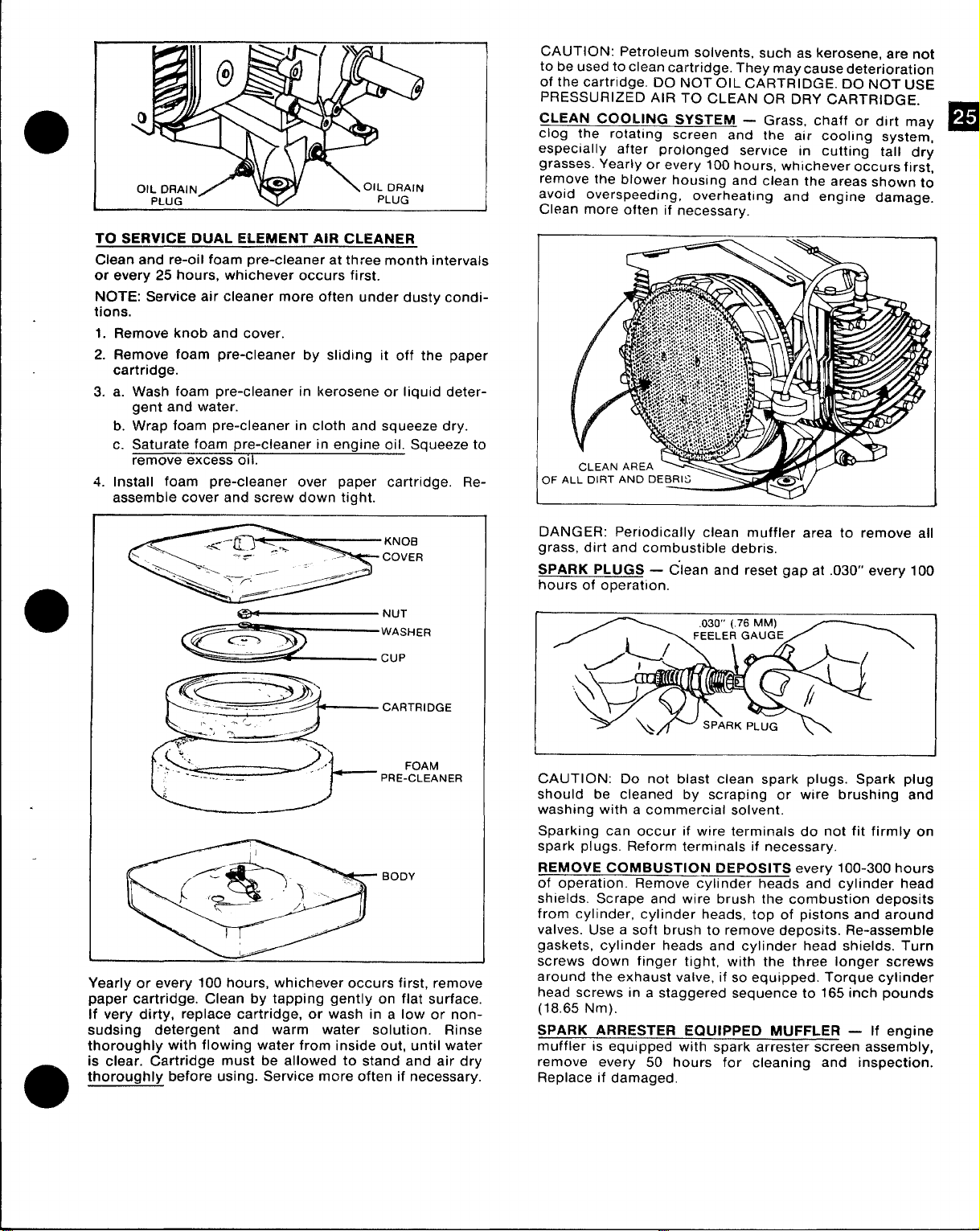
TO SERVICE DUAL ELEMENT AIR CLEANER
Clean and re-oil foam pre-cleaner at three month intervals
or every 25 hours, whichever occurs first.
NOTE: Service air cleaner
tions.
more often under dusty condi-
1. Remove knob and cover.
Remove foam pre-cleaner by sliding it off the paper
2.
cartridge.
3. a. Wash foam pre-cleaner in kerosene or liquid detergent and water.
b. Wrap foam pre-cleaner in cloth and squeeze dry.
c. Saturate foam pre-cleaner in engine oil. Squeeze to
remove excess 011.
4. Install foam pre-cleaner over paper cartridge. Re-
assemble cover and screw down tight
CAUTION: Petroleum solvents, such as kerosene, are not
to be used to clean cartridge. They maycause deterioration
of the cartridge. DO NOT OIL CARTRIDGE. DO NOT USE
PRESSURIZED AIR TO CLEAN OR DRY CARTRIDGE.
CLEAN COOLING SYSTEM
clog the rotating screen and the air cooling system,
especially after prolonged service in cutting tall dry
grasses. Yearly or every 100 hours, whichever occurs first,
remove the blower housing and clean the areas shown to
avoid overspeeding,
Clean more often if necessary.
overheating and engine damage.
— Grass, chaff or dirt may
9
-. . ..-
“— “-
Yearly or every 100 hours, whichever occurs first, remove
paper cartridge. Clean by tapping gently on flat surface.
If very dirty, replace cartridge, or wash in a low or nonsudsing detergent and warm water solution. Rinse
thoroughly with flowing water from inside out, until water
is clear. Cartridge must be allowed to stand and air dry
thoroughly before using. Service more often if necessary.
CARTRIDGE
FOAM
PRE-CLEANER
DANGER: Periodically clean muffler area to remove all
grass, dirt and combustible debris,
SPARK PLUGS — C’”lean and reset gap at .030” every 100
hours of operation.
I
CAUTION: Do not blast clean spark plugs. Spark plug
should be cleaned by scraping or wire brushing and
washing with a commercial solvent.
Sparking can occur if wire terminals do not fit firmly on
spark plugs. Reform terminals if necessary,
REMOVE COMBUSTION DEPOSITS every 100-300 hours
of operation. Remove cylinder heads and cylinder head
shields. Scrape and wire brush the combustion deposits
from cylinder, cylinder heads, top of pistons and around
valves. Use a soft brush to remove deposits. Re-assemble
gaskets, cylinder heads and cylinder head shields. Turn
screws down finger tight, with the three longer screws
around the exhaust valve, if so equipped. Torque cylinder
head screws in a staggered sequence to 165 inch pounds
(18.65 Nm).
SPARK ARRESTER EQUIPPED MUFFLER — If engine
muffler is equipped with spark arrester screen assembly,
remove every 50 hours for cleaning and inspection.
Replace if damaged.
1
Page 27
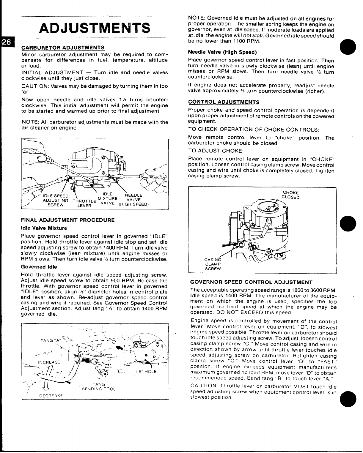
ADJUSTMENTS
CARBURETOR ADJUSTMENTS
carburetor adjustment may be required to com-
Minor
pensate for differences in fuel, temperature, altitude
or load.
INITIAL ADJUSTMENT — Turn idle and needle valves
clockwise until they just close.
CAIJTION: Valves may be damaged by turning them in too
far.
Now open needle and idle valves 1‘h turns counterclockwise, This initial adjustment will permit the engine
to be started and warmed up prior to final adjustment.
NOTE: All carburetor adjustments must be made with the
air ckwtner on ‘engine. -
NOTE: Governed idle must be adjusted on all ongirtes for
proper operation. The smaller spring
governor, even at idle speed. If mod.arate loads are applied
at idle, the engine will not stall. Governed idle speed should
be no lower than 1100 RPM.
keeps tho engine on
Needle Valve (High Speed)
Place governor speed control lever in fast position. Then
turn needle valve In slowly clockwise (lean) until engine
misses or RPM slows. Then turn needle valve M turn
counterclockwise.
If engine does not accelerate properly, readjust ntmdle
valve approximately % turn counterclockwise (richer).
CQNTROL ADJUSTMENTS
Proper choke and speed control operation IS dependent
upon proper adjustment of remote controls on the powered
equipment.
TO CHECK OPERATION OF CHOKE CONTROLS:
Move remote control lever
carburetor choke should be closed.
TO ADJUST CHOKE:
Place remote control lever on equipment in “CHOKE”’
pcsition. Loosen control casing clamp screw. Move control
casing and wire until choke is completely closed. Tighten
casing clamp screw.
to “choke” position. The
FINAL, ADJUSTMENT PROCEDURE
Idle Vahm Mixtuw
governor speed control lever in governed “IDLE”
Place
position. Hold throttle lever against idle stop and set idle
Spewl adjusting screw to obtain 1400 RPM. Turn idle valve
slowly clockwise (lean mixture) until engine misses or
RPM slows. Then turn idle valve ‘/2 turn counterclockwise.
t2mN?rll@d Idle
Hold throttle lever against idle speed adjusting screw,
Adjust idle speed screw to obtain 900 RPM. Release the
throttle. WJith governor speed control lever in governed
“IDLE” posjtion, align %“ diameter holes in control plate
and lever as shown. Re-adjust governor speed control
casing and wire if required. See Governor Speed Control
Adjustment section. Adjust tang “A” to obtain 1400 RPM
governed idle.
1’ DECRFAS’E
CtiOKF
CLAMP
SCREW
GOVERNOR SPEED CONTROL ADJUSTMENT
The acceptable operatlnq s~eed ranae IS ?800t03600 RPM,
Idle speed is 1400 RPM- T’he manu~acturer of the equ!pment on which the engtne
governed no load speed at wh[ch the engine may be
operated. DO NOT EXCEED this speed,
Engine speed
lever Move contro( lever on equipment, “O”, to slow~sf
engine speed possible Throttle lever on carburetor shoutd
touch Idle speed adjusting screw. To adjust, loosen control
casing clamp screw “C.”’ Move control casing and wtre In
dlrectlon shown by arrow until throttle lever touches Idle
speed adlusting screw on carburetor. Retighten casing
clamp screw “C.” Move control lever “D” to
posltlon.
maximum governed no load RPM, move lever “D” Ioobtaln
recommended speed Bend tang “B” to touch lever “A.”
CAUTION Throttle lever on carburetor MUST touch tdle
I
speed adjusting screw when equipment control lever
slowest
posltlon.
IS controlled by movement of the control
If engine exceeds equipment manufacturer’s
.\--
IS used, specifies the top
‘<FAST”
IS in
Page 28

o
●
Superseding Warranty
BIUGGS & STRAT7’ON ENGINE WARRANTY POLICY
effective October 1, 1976
Replaces all undated previous Warranties and all Warranties
dated before October 1, 1976
When warranty repair is justified. Briggs & Stratton Corporation welcomes such repair by any of its Authorized
Service Centers.
In most instances, the requests for warranty brought to the attention of
prompt routine manner with no question regarding their validity. However. some requests for warranty are received which are not justified. In these cases. engine owners may not be aware that the premature failure of their
engine was the result of abuse or neglect. or that the difficulty which they experience is
our service accounts are handled in a
caused by the equipment
rather than the engine.
BRIGGS & STRATTON WARRANTY covers only DEFECTIVE MATERIAL tind/or WORKMANSHIP.
ONE YEAR LIMITED WARRANTY
“For one year from date of purchase, Briggs & Stratton Corporation will replace for the original purchasers, free
of charge, any part, or parts of the engine, found upon examination by any Factory Authorized Service Center,
or by the Factory at Milwaukee, Wisconsin, to be defective in material or workmanship or both; this is-the exclusive remedy. All transportation charges on parts submitted for replacement under thjs warranty must be borne
by purchaser. For warranty service contact your nearest Authorized Service Center as listed in the ‘Yellow Pages’
under ‘Engines, Gasoline’ or ‘Gasoline Engines.’
TIES, INCLUDING THOSE OF MERCHANTABILITY AND
ONE YEAR FROM PURCHASE AND TO THE EXTENT PERMITTED BY LAW ANY AND ALL IMPLIED WARRAN.
TO
TIES ARE EXCLUDED. LIABILITY FOR CONSEQUENTIAL DAMAGES UNDER
EXCLUDED TO THE EXTENT EXCLUSION IS PERMITTED BY LAW. Some states do not allow limitations on how
an implied warranty lasts, and some states do not allow the exclusion or limitation of incidental or con-
long
sequential damages, so the above Iimitatian and exclusion may not apply to you. This warranty gives you specific
legal rights and you may also have other rights which vary from state to state.”
THERE IS NO OTHER EXPRESS WARRANTY. IMPLIED WARRAN-
FITNESSFOR A PARTICULARPURPOSEARE LIMITED
ANY AND ALL WARRANTIES ARE
NO REGISTRATION (WARRANTY) CARD IS NECESSARY TO OBTAIN WARRANTY ON BRIGGS & STRATTON
ENGINES. FILL IN THE REQUIRED INFORMATION AND RETAIN FOR YOUR RECORD:
(See Decal on Blower Housing for Model, Type and Code Number)
Engine Model No.
Dealer Purchased From
Type of Equipment
Name or Tracfemark of Equipment Manufacturer
If warranty service is needed contact your ne:lrest Authorized Service Center. For prompt attention your
will need to know the engine model. type and code number. the trouble experienced and the total number of
hours the engine has run. If you differ with the decision of a Service Center on a warranty claim. ask the Service
Center to submit all supporting f~lcts to the Factory for review. If the Factory decides tha_t your claim is justified,
you will be fully reimbursed for those items accepted as defective.
m
Type No.
(o\’er)
Code No.
center
Page 29
❑
~a avoitl mismderstandimgs which might occur between engine owners and authorizrcl Briggs & Stratton service
acommts, we are listing causes of engine failures,
Stratton warranty.
a
*
where repair or replacement is NOT covered by !3ri~s &
NWMAL WEAR:
Warranty wil[ not cover repair where normal use hasexhaustedthe life of a part or engine. Engines, like a[l mechanical devices, need periodic parts replacement and serviceto perform well. It should be remembered that the service
life of any engine is dependent on the care it receives and the conditions under which it has to operate. Some appli-
cations, such as tillers, trash pumps, rotary mowers, are very often used in dusty or dirty conditions. which can
cause what appears
abrasive material, which has entered the engine because of improper maintenance. is not cw~’ered by Warranty,
to be premature wear. Such wear, when caused by dirt. dust, spark plug cleaning grit or other
ABUSE OR NEGLECT:
Brnt or broken crankshafts: Such damage is normally the result of abuse,
the cutter black on a rotary lalvn mower, and is not covered by \Varranty.
2.
Engine repairs rquircd from the use of old or stale fm>l arc not covered by lVarranty. Such failures would
include sticking va[ves,
through the use of stale fuel. .Always use cIwn fresh regular gasoline.
Parts which are scorecl or broken !wcause an engine was opc>ratecl without sufficient lubricating oiI or the
I
I
I
I
I
I
3.
proper grade of Iubricat ing oi 1 are not covered by \\’arranty. Check oil level at least ev(>ry five hours ond
refill when necessary. Change oil at recommended intervals.
-1.
Damage caused by o~whcating or overspeeding is not covered by TVarranty,
occurs if the cooling fins become plugged with dirt, grass or dt>bris, or if an engine is operat[’d in a confined
area without sufficient ventilation. Clean fins on the cylinder, cylinclcr head and fiywhecl rx’gularly.
Damage or wear caused by dirt \vhich cmters the engine
5.
not covered by lVarranty. Clean and re-oil the air cleaner regularly,
6.
Damage or wear caused by grit from blast cleaning spark plugs is not covered by lVarranty. \ve do l]ot
approvt~ of cleaning spark plugs on an abrasive blast cleaning machine, since grit
later entm the engine.
7.
lVarranty does not cover the tune-up or a(ljustrncnt of an (mgin{ unl(ws the ncxd for such repair is the result
of defects i]) material or workmanship or both. If c(luipmcnt is ass(mll)led and adjust(, d l)v the owner, the
cmgint’ Op(’rating and \laintcmance
minor acljustmwts.
13rolwm parts. ~thich result from exc{,ssive vibration ca~]sed by IOOSC(ngine mo~lnting, loosr clltter blades,
w
blad[’ Ilnlmlallc(’.
arr not cot(’rc(l I)y \Varranty.
impropi’rly attaching c(]uipment to engine crankshaft, uv(~rspetding or abuse in operation,
and carburetors and fuel pipes which are clogged by gum d(~posits tvhich form
becausr of improper air cleaner maintenance is
Instructions arc s(lfficicmtly cl(ar to p(mnit the a~x’rag~ owner to make
Such minor adjustments are NOT covered by kVarranty.
such as striking a soIid object with
Ov<’rspecding or overheating
e
cm] remain in th(’ plug, a]]d
Repair or adimsttn(mt of associated parts or asselnblies such as clutches,
which tw( not of Briggs & Stratton manufactllrc, \vilI not I]c coi(m’d by Briggs & Stratton lf’arranty.
10,
OrLly ORICIIN:\L Briggs & Stratton parts,
kVarrantyu
WARRANTY !S AVAILABLE 0NL% THROUGH SERVICE CENTERS WHICH HAVE BEEN AUTHORIZED BY THE BRIGG$
& STRATTON CORPORATION. Y~UR NEAREST SERVICE
hone
DIRECTORY, UNDER “ENGINES, GASOI.INE” OR “GASOf.lhfE ENGINES.”
or parts approved b? Briggs & Stratton ]nav be cwered by
CEN’TERIS LISTED IN THE YELLOW PAGES OF YOUR Telep-
transmissions, remote controls, etc.,
Page 30
ENGINE
engine instruction brochure is included with this manual (see
Arr
index) which may assist
ROBLEMS:
*
@
ENGINE FAILS “m START
o IENGH4E RUNS ROUGH
o ENGINE BACKFIRES
ID ENGINE FAILS TO ACCELERATE
* ENG!NE REDUCES SPEED TO Low RPM
UNDER ILOAD
CAUSES AND/OR SOLUTION:
1. Loss of fuel
A. Empty gas tank.
B. Plugged fuel line or filter.
C. Defective fuel pump. (Replace with mfg. suggested
replacement parts only).
D. Gas line kinked, crushed or quick disconnect inside the truck
not connected.
2. Blown master fuse.
A. Electrical short.
B. Defective fuse.
3. Worn or maladjusted points (Onan eng. Only) (Briggs has
electronic ignition).
A. Remove and replace points and condenser.
B. Clean and adjust points.
4. Defective spark plugs
A. Remove and replace.
B. Clean and regap.
5. Defective spark plug wires
A. Sparkplug wires along with many others may, at certain points
come in contact with heated parts (exhaust manifold) or
a
abrasive parts (sharp metal, tefIon hose).
into consideration for electrical shorts.
B. Remove and replace.
6. Low compression
A. Defective valve.
B. Stuck valve.
C. Worn compression rings.
D. Defective piston.
7. Float switch in recovery tank inoperative. NOTE: Temporary
repair permits disconnection of float switch wire between tank
and machine. Continued operation with this condition will
compromise vac blower.
A. Switch stuck on upright position by foreign material.
B. Defective float switch.
8. Engine will not turn over
A. Dead battery
B. Loose terminal connection on battery or ignition switch.
C. Defective starter.
D. Seized engine or blower.
9. Defective Carburetor or gas leakage.
A. Clean carb.
B, Replace carb.
C. Choke locked in closed position.
you in resolving engine related problems.
This maybe taken
A.
Carbon build-up may be excessive if carb. or valves are
improperly adjusted, engine RPM too low, improper spark plug
gap.
Remove cylinder heads and eliminate carbon build-up with
B.
wire brush.
12. Incorrect timing
A. Timing may ~ecome offset if point box is not secure or if
points are out of adjustment. (Onan only).
13. Dirty air cleaner
A. If exhaust gaskets do not seat properly or heat exchanger
gasket is bad, exhaust may heat and melt the the air cleaner
requiring much clean-up repair.
14. Clogged fuel filter
A. Remove and replace
Low oil level or malfunctioning oil pump
15.
A. 011pressure sensors can be installed on the engine. This will
eliminate many problems which may occur.
16. Vacuum tank full
A, Empty vacuum tank
●
E
D. When replacing fuel pump insure that it is the same pressure
rating recommended by mfg.
10. Improperly adjusted carb. NOTE: A comprehensive manual is
available and defines necessary adjustments.
a
A. Incorrect air mixture ratio adjustment.
B. Incorrect float level adjustment.
11. Carbon build-up in cylinders. NOTE: Carbon build-up can be
minimized by using unleaded regular gas. Should carbon
removal be necessary, reinstall heads with new gaskets.
Page 31
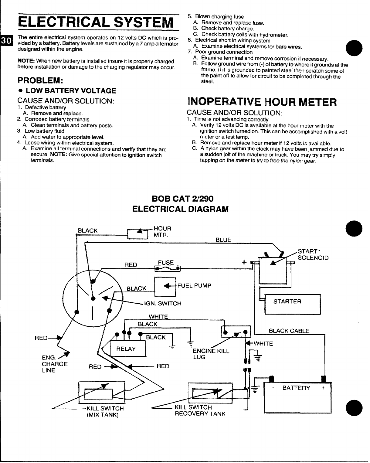
ELECTRICAL SYSTEM
Tha smtire ehsctrical system operates cm 12 volts DC which is providad by a bathery. Battwy levels are sustained by a 7 amp alternator
demigrwd within the engine.
NOTE: W1’risnmawbattery is installed insure it is properly charged
Wore installation m damage to the cha~ging regulator may occur.
PROBLEM:
@ LOW H~lTIEFly
VOLTAGE
5. Blown charging fuse
A. Remove and replace fuse.
B. Check batteiy charge.
C. Check battery cells with hydrometer.
6. Electrical short in wiring system
A. Examine eiecttical systems for bare wires.
7. Poor ground connection
A. Examine terminal and remove corrosion if necossa~.
B. Follow ground wire from (-) of battery to where itgrounds at ttwa
frame. 1$it is grounded to painted steel then scratch some of
the paint off to allow for circuit to be ccwn@et@dthrough ttm
steel.
a
CAUSE ANWOFI SOLUTION:
1.
Defective battery
A. Remove and replace.
2. Corroded battery terminals
A. Clean te!rnmirnalsand battery pasts.
3. Low battery fluid
A. Add water to appropriate level.
4. Loose wiring within electrical
Examine all terminal connections and verify that they are
A.
secure. NOTE: Give special attention to ignition switch
terminals.
system.
ELECTRICAL DIAGRAM
BLACK
#l
l\
INOPERATIVE HOUR METER
CAUSE AND/OR SOLUTION:
1.
Time IS not advancing correctly
Verify 12
A.
ignition switch turned on. This can be accomptisheci with a volt
meter or a test lamp.
B.
Remove and replace hour meter if 12 volts is available.
c.
A nylon gear within the clock may have been iammed due to
a sudden jolt of the machine or truck. You may try simply
tapping on the meter to try to free the nylon gear.
BOB CAT 2/290
HOUR
MTR.
volts DC is availatile at the ~~ur meter with the
BLUE
N
ncu
Em
CHAFWIE
LINE
3
RED
(MIX TANK)
a’”ELpuMp
_ IGN. SWITCH
WHITE
“LACK
1?
RECOVERY TANK
‘?1
BLACK CABLE
Page 32

MACHINE
INSTALLATION
INFORMATION
There are two ways of positioning the machine in the truck as shown
on the following page. There are also two locations for the vacuum
recovey tank to be positioned. First, the standard way with the tank
directly alongside the machine. Second, with the tank across the
back ofthe machine as shown below; this location is most space efficient.
MACHINE
PROPANE TANK PLUMBING
---->
J-35’ 1~, /
-m ‘“”d
— &
SHOULD BE MOUNTED (THBu FLOOR)
CARRIAGE
-e / \\
an,
PROPANE FIT+NG
PRIJ&.:::ANK
F’”~q [// ‘“”y ~
‘OcK‘ASHY&
/ j&-Pf30PANEFim(Nc3
BOLT
\
Whichever way you select, make
ured to the floor of the van to insure driver safety.
It isimportant that the machine be placed as close to the door as pos-
sible so that outside air can be pulled intothe engine for proper cool-
ing.
It is recommended by the manufacturer that the
exhaust from the front of the machine be vented down under the
truck to prevent carbon monoxide from entering the job site. Always
park the truck so the exhaust is blowing away from the job site.
The manufacturer also recommends that installation of aluminum
vents inthe truck roofto allow heat from the heater to escape.
,.
1“’1-’.’m
propane tank or a portable gas can inside the truck. The-heater is
an open flame type and could cause afire or explosion.
Mount a fire extinguisher just inside the rear or side door for
emergencies.
Never o~erate this machine with a portable
sure the tank and machine are sec-
MACHINE ‘TIE li30WWNCLEAT
llmAAstnRA-mN
10 MAXIMUM
SET BACK OF
MACHINE FROM DOORWAY
THRU-FLOOR GAS HOOK-UP
AND INSTALLATION
THRu FLOOR
GAS HOOK.UP
(1-10)
FITTING
(,%SRS.STR ELBOW)
G
SCREW
, /.\&
hi?
lb-k-’A 2-PUT’
u
9
/
HOSE CIAMP ,,<<
&
HOSE
BARS
/
RW3
i
“19
&/
c-
FUEL
FILTER
F?’W
r-
L&
SOCKET
HOSE (CUT TO LENGTH)
HOSE ‘““
“Rs G
P.
l’,
QUICKCONNE.T
Y’
FITTING
\
L’
HOSE
E)ARS
c%
—
NOTE: uSE TIES TO SECURE T-FITTING
TO THE FRAME AND TO STABILIZE
HOSE AT A MINIMUM 6’ FROM
THE EXHAUST PIPE.
-QYJ!9!Y’/---’
G---J
Page 33

WATER SOFTENER
Many areas of the country have an excess of minerals in the water
which results inwhat iscommonly called “hard water”. These miner-
als tend to whsre to the insides d heater coils and other parts ofthe
machimas causing damag~ and a lass of cleaning effectiveness.
FlaPcIrts from sevw’al of our machine users commending the results
I
of ~ht+use af wab.m’softc$nersin conjuntilon with the~r machines
prompts us to recmnm~nd the procedure to everyone in a “hard ,/’\ i
water” area.
The relatively law cost of a water softener service is more than made
up for in the increased life of machine parts and continued cleaning
efficiency. The water sofkmer will also increase the effectiveness of
the cleaning chemical being used, therefore, less chemical will be
needed.
Contact a water softener distributorinyour area for information on the
rental of a simple water treatment unit to carry in your truck.
to change the water softener in accordance with the capability of the
sdhwkw. Example: If the softener will treat 900 gallons of water and
the machines uses an average of 30 gallons per hour of use, and an
average of 5 hours a day, would be 150 gallons a day. 5 days would
equal 7!30 gallons ofwater, therefore, th@softener would be changed
every Gworking days for maximum softening.
Be sure
/<
‘\
.::,/
\,,
WAt+dDASSEMBLY
\,/,&~:_:@
FRAME TUBE
5
S SOLUTION TUBE
\
~ :;:
‘/,’
\
ASSEMBLY
SSXREWA
WAND LIPS
bi&NDLE CLIP
VALVE ASSEMBLY
.ASSEM13LY
HANOLE SLEEVE
&’
t
.-+
S S HANDLS [QU&OE)
‘s NU1
.. m
-:.$9 “
FAuCET
JET ASSEMBLY
BODY
BRASS C&P
QUICK CONNECT PLuG
LIZTE
@QJ
x“
\
Page 34

OPERATING
INSTRUCTIONS
START UP
Perform daily/periodic maintenance as specified by the owner’s
1.
manual.
2.
Connect all required hoses.
Connect cleaning tool to length of hose required to perform
3.
cleaning.
4.
Caution: Mix tank must be full prior to ignition.
Start engine (choke as required). Engine is at operating speed
5.
(recommended -2600 RPM). Aliow warm-up period of 2-5
minutes.
6.
Spray wand to void all air from system. As the mix tank is in a fill
cycle, the chemical flow meter may be adjusted to your desired
setting. NOYE: Recommended carpet cleaning pressure is 250-
300 Psi.
7.
Once all air is voided from system, heater maybe ignited. NOTE:
If not familiar with operation of this heater, refer to heater section
of the manual.
A. Open propane valve on the tank.
B. Ignite pilot on the heater.
C. To ignite burner, turn dial to on position.
NOTE: Ifyou suspect that the unit has been frozen-DO NOT light
the heater. Thaw the heater and check for leaks.
Turn on burner, adjust dial to normal or slightly below for 200
8.
Deg. F.
9<
Commence cleanirm o~eration
NOTE: Chemical fl~w “meterset at 5 GPM is a 1 to 30 mix ratio
and 10 GPH is 1 to 15 ratio. When flow meter is set at 10 GPH,
vou will be usina what most chemical manufacturers recommend
&5 GPH. -
O
SHUT
Turn heater to off position. Spray wand for a least 3 minutes to
1.
allow the heater coils to cool.
2.
Close valve on propane tank.
Remove vacuum hose.
3.
Flush clear water through chemical system for 10 seconds.
4.
(vinegar should be rinsed through system weekly). Turn off
chemcial
Turn on cleaning tool to flush chemical from unit hoses and
5.
cleaning tool.
NOTE: If freeze guard isnecessary, perform steps 1 & 2 of freeze
*
guard procedure at this time.
At thistime, the biower should be lubricated with LPS 1 orWD 40.
6.
Shut engine down.
7.
Drain vacuum tank. Vacuum filter should be cleaned prior to
8.
mobilization of van.
NOTE: If freeze guard is necessary, perform steps 3-9 of freeze
guard procedure at this time.
DOWNI
flow meter.
MACHINE
HIGH PRESSURE GAuGE SET AT
(200 PSI WITH $00 HOSE)>
CONTROL PANEL
HOUR METER
a
BLOWER, E.GINE ExHAusT HIGH PRESSURE
T
~w
I
CLEANING sOLUT10.
CONNECTION
LEG HOLES ~lx ~*NK DRAIN
PETCOCK VALVE
& HOSE
OPERATION PRECAUTIONS
MACHINE ADJUSTMENTS:
Although this unit has been factory adjusted, it may require additional adjustments to achieve optimum performance; i.e. altitude
may require carb adjustment and ambient temperatures may require
heat control adjustment. When required, consu\t an authorized rep-
resentative.
ENGINE COOLING:
_ Units employing air cooled engines must not
be incapacitated within a van with doors and windows closed. Excessive temperatures within the engine will result in premature engine failure and a compromise of applicable warranty.
LEVEL OPERATION:
level ground not to exce%d’ + or – 10 deg.. Failure to ins~re proper
leveling may prevent proper internal lubrication of engine, vacuum
and)or high pressure components.
FREEZE PROTECTION:
~ Mother nature gives little warning as to her cold
spells. Therefore, protecting this equipment from fr=ezing will save
costly down-time. Placing an electric heater in the truck or parking
the truck indoors,
Durina o~eration. van ortrailer must be ~arked on
will help to insure against freezing.
LIGHTING HEATER:
the heater when lighting.
Never put your face down close to the opening of
STRONG PROPANE ODOR:
propane around the heater.
Never light the heater if you smell a strong odor of
Page 35

HEATER:
~
boxes, chemical jugs, etc., as this willblockthe flow ofairrequired for
a clean burning Iwlu@r.
I%evar pk3 things around the Iwater, i.e. hosas,
OPEN FLAME:
lQ?wENJR
therefore, do not remove engine gas limewhile troubleshooting or
any flammable material in the truck with heater operating.
store
ternelrnbw thatthis heater is an open flame,
FREEZEPROTECTION
Any fre~zing of this machine is not covered by warranty and during
tl’m colcfar
most
THE
1.
Run machine before Ioaving for the first job to insure nothing has
frozen the night before, including hoses and wand.
Insulate the garden hose from the cold ground by running it
2.
through an extra 1 %
L@av+etruck doors closed until time cleaning begins, then open
3.
slightly for ventilation of air cooled ‘engine.
4,
On
thmefo~e, venting the warm exhaust over to blow on the propane
tank will stabilize thra propane flow. (This is necessary if you
notico a drop
In
!5.
help pmtf?ct ttw w-lit.
Don’t procrastinate during the cleaning operation or the hotwater
6.
salution line will also freeze on the ground. The solution line
should btrinsulated in extremely cold climates.
7.
Whenever possible, the truck and machine should be stored ina
tvaatd gfwage at night or over the weekend. Ifnotpossible, place
a 1500 watt electric heater inside the truck,
machine.
tum on the truck ceiling and the possibility of it going out is higher.
Ifthe machine and truck are left outside with a heater, you should
first drain
hoses. (They freeze also.)
TCl DRAIN THE
A.-’ “ ‘“ ‘“s “
Bemre snumng on me macnme, remove me cnemlcal Ime worn
the chemical jug and place in a mixture of 50/50anti-freeze and
water. With tt%acleaning tool on, allow mixture to fillchemical system back to the chemical mix tank.
B.
Loosen the petcock valve on your bypass drain hose and allow
the
To remove the water from the heater and pump use the freeze
c
guard kit which is a small air compresor that can be plugged into
the clash board lighter inthe truck, or
the correct connectors, first blow
ticm male quick connect.
heater back through the pump and into the chemical mix tank to
force that water into the chemical mix tank to be drained out.
months of operation, cafieful protection should be of ut-
cmnccwn.
FOLLOWING PRECALJTICXNS ARE RECOMMENDED:
inch vacuum hose.
extwmwly cold days propane does not vaporize as quickly,
in l’mat or a low burning flame in the heater, )
colder climates, insulating the truck wails arid floor boards will
Nrmmruse a propane heater-it causes excessive mois-
all possible water from the machine cleaning tools and
MACHINE, FOLLOW THESE STEPS:
water todrain thoroughly from the mix tank.
air into the high pressure solu-
This will force the water through the
be drakwd out through the petcock valve to the ground.
Next, MOW the air into the incoming water quick connect and
aimed directiy at the
.,, . . . .
air at the gas station. Using
CLEANINGAND
CHEMICAL
PRECAUTIONS
INFORMATION
Your mobile carpet cleaning plant has b~en engineered using the
latest and most sophisticated technology available, to produce the
finest carpet cleaning results possible. Despite this however, it re-
mains only a tooi ofthe carpet cleaning trade, and it can produce only
as good a job as the person operating it,
There are no short cuts to good carpet cleaning, it requires time,
cleaning knowiedge and the use of good chramicals.
Manufacturer recommends the use of spotting agents, and traffic
lane cleaners prior to the actual cleaning of carpeting, as r~quired.
Manufacturer recommends setting heater thermostat
ting when cleaning synthetic fiber carpets, and at ‘warm’ setting
when cleaning natural fiber carpets.
~ Wh en cieaning cut-pii~ acrilan plush carpets, set
heater at ‘warm’ setting. Using bighw heater setilng may resuit
fiber damage on this type of
The use of some chemicals through your mobile carpet cleaning
plant can seriously damage the internal plumbing, high prmsure
pump and heater. (Chemicais such as concentrated ac~dsand some _
paint oil and grease removers wihigh concentration of solvwts.)
Manufacturer recommends only the use of chemicals containing rust
and corrosion inhibitors and water softening agents to Dr&vent
chemical build-up.
NOTE:
At no time should a chemical solution with a pH of less than 7 or
higher than 10 be used in the unit.
1234567891011 121314
I I i
I
I I i
4— ACl@ —NEUTRAL—
PI-4
carpet.
CHART
I
I I
“’h’’”’~
CLEANING STROKE
PROCEDURE/OVER-WETTING
PURPOSE:
To eliminate excess moisture remaining in the carpet fiber and the
sawtooth appearance which results from diagonal movement of the
cleaning tool on all types of carpet.
at ‘normal’ s@t-
in
e
J
.
To bo sure
ccmnec$ors
HE
8.
I%waxing will cause?GRIEF, MONEY and DOWN-TIME.
mess ‘with mothw’ nature! !WlwxmbW to UAXW the petcock
valve pIFkw to rmxt ,qmerath-t 0$ your EWKat
all water is out of the system, aiternate between quick
several times.
SURE IT’S PFlOTECTED!
2/290.
Don’t
PROCEDURE:
Always move the cleaning tool in smooth forward and backward
strokes.
tion is injected into the carpet. When extracting (drying), apply firm
pressure on the forward stroke to ensure a positive “lock” for the
vacuum and minimize the “hopping” effect resulting on unsmooth
carpet. During the forward and reverse strokes, movement to the
Apply slight pressure to the forward stroko whii~ tl’m soiu-
0
Page 36

right or left should only be accomplished at the extreme rear of the
stroke. Overlapping is also important to ensure even application of
solution to prevent saturation when cleaning wand is stopped twice
at the same point at the rear of the cleaning stroke.
Failure to adopt this procedure can result in increased chance of
“clean
e
periods.
streaks”, fiber shrinkage, brown out, and longer dving
a Clean vacuum tank thoroughly with high pressure washer.
@ Flush water and chemical system with 50/50 white vinegar
solution.
@ Check
LWWRTANT: Record date and machine hours on mairrte lance
chart.
engine M%4’s - adjust to 2600 FIPM’s as
needed.
m
INCORRECT METHOD
\/
CORRECT METHOD
—
%YYfxq/qJJ&!,;
.
OVER-WETTING
Over-wetting is annoying to all concerned and sometimes leaves a
bad impression of the cleaning process used.
There are several areas that will cause over-wetting:
1. Too few vacuum strokes or improper sawtooth vacuum
strokes as shown above.
2. Obstructed, kinked or cut hoses.
3. Vacuum tank drain valve left partially open.
4. Clogged vacuum blower filter or vacuum tank lid not sealing
properly.
5. Cleaning a heavily foam-saturated carpet without defoamer.
(We recommend crystal type.)
●
—
MAINTENANCE
PROCEDURES
To avoid costly repairs and down-time, it is imperative to develop
and practice good maintenance procedures from the beginning.
These procedures fall into daily, weekly, monthly and quarterly increments, and are outlined below. We have provided a maintenance
log for your convenience on the following pages; it is recommended
that you affix a copy of the logon the vehicle door near your unit for
n
convenience and to serve as a maintenance reminder.
DAILY
@ Check engine oil level.
e Inspect garden hose screen - clean as needed.
e Visually inspect machine for loose wires, oil leaks, water leaks,
etc..
o Inspect recovery tank s/s filter and filter bag for tears, holes, etc. -
clean, repair or replace as needed.
o Lubricate blower with
WEEKLY
Change engine oil. (25-30 hours of operation)
Check engine air cleaner filter - clean as necessary.
Check high pressure pump oil - add as necessary.
Check drive coupler set screws - tighten as needed.
Check pump drive belt for wear - tighten as needed.
Check pump pulleys - tighten as needed.
Check fuel lines for wear/chafing.
Check all nuts and bolts - tighten as needed.
Check heater burner assy. union for tightness/leaks.
LPS-I or WD-40 through blower inlet.
STROKE STROKE
OVERLAP
BETWEEN STROKES
CLEANING
MONTHLY
● Grease blower bearing fittings.
aI Remove, clean and reinstall
@ Remove pressure by pass valve stem, grease cup and stem,
reinstall.
@ Check water level in battey. Clean connections as needed.
M%W3T.AFW: Record date and machine hours on maintenance
chart.
engine air cleaner filter.
QUARTERLY
s change oil in blower (see blower manual).
e Check engine compression.
e Check for combustion chamber carbon deposit
e Change spark plugs (see engine manual).
‘—}j&&,er
OVERALL CARE OF UNIT
MAINTAINING THE ORIGINAL APPEARANCE OF YOUR UNIT IS
IMPORTANT FOR TWO REASONS:
1. It represents a big dollar investment for your cleaning business
and its appearance should reflect that fact. A dirty machine is not
professional!
2. Maintenance, troubleshooting, and repair is much easier to
accomplish on a clean well maintained unit. Regular cleaning of
the machine offers you an opportunity to visually inspect allfacets
of the machine and spot potential problems before they occur.
FOLLOWING MAINTENANCE IS RECOMMENDED BY THE MANUFACTURER AT THE FREQUENCY INDICATED.
AFTER EACH JOB: Check recovey tank, s/s filter and filter bag as
required.
DAILY: Wipe machine down thoroughly with a damp cloth; flush recovery tank out thoroughly. Empty filter bag and inspect for rips,
tears, etc. - replace as needed; remove, thoroughly clean and
reinstall stainless steel filter screen in recovery tank; inspect and
clean vacuum slot on cleaning wand; check wand head for sharp
edges that could tear carpet - file down as needed; clean wand with
stainless steel cleaning compound to maintain original appearance
(available through grocery stores); wipe down vacuum and high
pressure hoses as needed - visually inspect for cuts, etc..
WEEKLY: Wipe down entire unit as needed - apply good coat of
auto wax to all painted surfaces inside and out, and to control panel;
thoroughly clean recovery tank using high pressure hot water (unit
with optional high pressure cleaning gun may be used for this); re-
move stainless steel filter in recovery tank, thoroughly clean remov-
ing all lint build-up, inspect for damage and reinstall. Remove filter
bag, thoroughly clean and reinstall - iftorn, replace; empty chemical
from chemical container, wash out thoroughly to remove any chemi-
cal build-up; inspect chemical feed line strainer and use 50% white
vinegar/water solution to remove any chemical build-up; thoroughly
clean wand and inspect for clogged jet, debris in vacuum slot and
leaking fittings at valve. Apply light coat of auto wax to wand;
thoroughly clean vacuum and high pressure hoses including hose
cuffs - inspect for wear or damage to hoses and quick connect fit-
tings. Inspect garden hose connect/adapter screen for debris, re-
move and clean thoroughly. Inspect all propane and gas lines for
wear or abrasions that may cause possible fuel leaks.
Page 37

DAILY CLEANING & INSPECTION
Engine oil - check
Garden hose screen - clean
Machine -
Clean wc tank filter bag after every job
Blower inlet - spray with U% 1 after last job
general inspection
MAINTENANCE LOG
WEEKLY
MAX HRS
25
25
I
25
I
25
25
25
25
25
25
25
25
25
ENGINE OIL change
BLOWER check oil level
PUMP OIL check
‘m’”= COUPLER tighten set screws
,.-, - .i
BAITERY LEVELS check
I-BEATERBURNER ASSfvltightness/leaks
VACUUM TANK clean
WIRING
CHEMICAL SYSTEM flush w/vinegar
SERVICE
SERVICE
& PULLEYS
l#W3 check for chafing
BOLTS check tightness
check for chafing
check tightness
MONTHLY SEFWKX!
100
100
100
300
300
300
BLOWER grease bearing
ENGINE
BYPASS
AIR CLEANER clean
VALVE grease cup &.stem
QUARTERLY SERVICE (3 MONTHS)
SLOWER OIL change
ENGINE impression
SPARK
PLUGSchange
DATWHRS
I
I
I
I
DATE/HRS
I
I
1
I
I
DATE/HRS
I
I
DATE/EIRS
I
I
DATE/HRS
I
1
DATE/HRS
I
I
I
DATE/i-lflS
I
I
1
I
1
I
.
‘e
 Loading...