

Page 1
HGauaCat
HYDRA##!iiS-EY%
3+9
Corporation
Page 2
AquaCat(fiontview.featureslabeled).......................t.............................8
AquaCat(sideview.featureslabeled).............................................t.........8
CatPumpModel290
DismantlingCatPump
VanguardOHVEngine.........................................................................2l
.........................!.!..............................,,,,..!....,..........
....................................%...............<.....#...................
HOURS
Monday -- Friday
8:00 am To 5:00 pm
PACIFICSTANDARDTIME
GENERAL INFORMATION
'l~oodlnstallation (ontmckbed)..............................................................4
4strotuti installation..............................t.......................................c....l.4
Machinebnfiguration ........................................t......................................5
~ru.floorGas Hook.upandlnshllation...................................................5
WaterHardnessMap............................t................................................6
WaterSofienerMok.up.............................................................................6
WATER & CHEMICAL SYSTEMS
AquaGtWaterFlow ............................................................................lO
ChemicalPropotioningandLeveltintrol ..............................................lO
CAT PUMP
PumpingSectionCut.awy .................ll......4..c............l.......j....+o.4(..q4...l3
PistonModel290ExplodedMew...
BypassValveNsemb& .........................................................................l7
AquaGtWaterFlow ..........................................................................l7
VACUUM SYSTEM
Vacuum Flow............l..l...l.................4......c..........................c....l..l...l8
VacuumTankRlterBag...........t............................................................l8
BlowerLubePoR..................................................................................l8
VacuumBlowerMotorLubrication.........................................................2O
VANGUARD OHV ENGINE
OilMscos~Chti ...................................................................................~
OilRllandUpStick......................t.........................................................~
EngineComponenk..........................................................................~
EngineComponents(continued)
CarburetorAdjustmentScreW........t....................................................23
GovemedldleSpring...............................................................................23
Oil Filter/ Oil Drain
RoundDualArCleanerElement...........................................................24
SquarehalNrCleanerElement ...........................................................24
RoundDualElement.........t.................................................................25
CoolingSystem..
Sparkplug..............................................................................................25
FuelFilter................................................................................................25
ELECTRICAL SYSTEM
ElectricalElagram
.............................................................................24
.....................................................................................
............................,,,,..,.,,,,.... .... ....,,,...,,,.,,..,,,,!.,.....
...........................................................
.............................................................23
14
25
31
@@@@
,,,.y)!:,yiy’
PST
‘$@$&*:.
ROCK MT.
TELEPHONE NUMBERS
(206)775-7272
(206)775-7276
(206)775-7275
(206)771-7156
G 1991HydraMasterCorp.
Printedin U.S.A.
.~<jj$~.’
CENTRAL
GeneralOffices
Parts Department
ServlWarranty
FAX
“Yl:;j’%
EASTERN
CLEANING & CHEMICALS
pH~afl ..................................................................................................W
CleaningSkokeMethod.....................t.................................................~
CLEANING WAND
WandValve~sembly .......................................................................~
Jetksembly ..........................................t....t..........................................~
Wand%sembIy....................................................................................~
Page 3
GENERAL INFORMATION
WarningandCaution
HowtheSystemsWoks ...........................................................................2
.,,,,...........................,,,,,,,,.,,,,....,,..,,,,,,.!,,,................#
Naming:DONOT
Naming:DO...........................................................................................
3eforeStartfng
2ilRecommendations.............................................................................
2
‘uel Recommendations
:arburetorAdjustments
,,,.,,,,,...,...,..................................................................
!....0......,,.......................................................................!...
..........................................................................23
..........................................................a.t.............23
21
22
E
~draMasterHoum& PhoneNumb~ ....................................................2
AquaCatMactine Spcifications ............................................................3
Purchaser’sResponsibiiii
SalesRepresentative'sResWnsibilw....................................................4
TruckPreparation
PlacementofUnitinVehicle......................................................................4
TruckPreparationillustration.................t.................................................4
Machineinstallation................................................................................5
S~re PaflsRecommendation..t...............................!.............................5
PartsOrder,.,,...4.....!..................................!,,......................!......................
HardWaterAreaMap
WaterSofiener.........................................................................................6
WastewaterUs~salAWlso~ .......t.........................................................6
AQUACAT 3.90 PERATING INSTRUCTIONS
Sta~Up. ...............................................................................................8
Shutmw ........................t......................................................................8
FloodDamageWork .
OPERATING PRECAUTIONS
MachineAdjus~enb .............................................................................9
Cautions and Warnings................................................................9
WATER & CHEMICAL SYSTEMS
Water/~emicai FlowO~ration ...............................................................g
AquaUtWaterFiow. t....t.....................................i...............................lO
ChemicalSystemMaintenance
ChemicalTankTroubleShootingGuide
.,..,,,,.,,.......................,,,,.,!,............................................
........................................................................
,................!!........................!....................................
.. ,.,.,.,!.....,,.................,,,,,...........................!..............
..#...........l...!..!...!.................##.....!......l...!.!lo
..........!......!.!..........t#...#..............ll
:NGiNEMAiNmNANcE .........l.....r$o...................................................24
3iiChange
Nr~eanerMaintenance ........................................................................24
:Iean Engine,RotatingScreen,CoolingSystem,SparkArrester..........25
4
~epiaceSparkPiugs,ReplaceFueiFilters
EngineMaintenanceSchedule
SeneraiInformationaboutEngine
4
3toragelnstiudons ................<......c......l..............c..l......l.......t.t.l....o...$(.27
3ewice& Repairinkrmation...................................t..............................27
UanguardEngineWarranty
SuprsedingWarran~ ....................................................................!28
UmtiedWarmn~forVanguard ~gines ..................................................28
Waran~Period .....................................................................................29
5
ENGINETROUBLESHOOTING............................................................W
6
ELECTRICAL SYSTEM
ElectricalSystemandTroubieShootingGuide
FREEZE PROTECTION
AquaCat
CLEANING & CHEMICALS
8
Precautions
CleaningStrokeProcedure/Over.Wetiing............................................W
CLEANING WAND
Wand,Jet%sembly&WandAsembiy Paflstists ................................W
MAINTENANCE
Procedures
OverallCareofUnit..................................l..................................o.....oct..
MaintenanceLogs........................................................................37.38
...........................................................................<..............24
..,,..,..,,,,,.,.,...........................25
...............................................................26
..,,<..,,,,.....................,,,,,............,,...!..0.
.....................................................................28
.,..............!......................31
..........................!...........................................................................
,,.,..,,,,,.,....................,,,,!,.,,,..............................!......,,.,!...
.,..............,!........................................................................
27
32
33
:
CAT PUMP
CatPumpMode12900~ ratinginstmctions...........................................ll
CatPumpSWcifiMtions ................t....cc..l..cc..c.........t........................l...ll
GeneraiinfimationhrCat PumpRepair................................................l2
SewicingtheDschargeValves& ValveSeats.........................................l2
Sewicingtie PumpingSection.........l.............................l.......................l2
SewicingSleevesandSeals..............................................................l2
SewiceKk...c.......c.(.......o...........r....cc...l............r..................l..............l3
Modei2WPafls Dst..............................................................................l4
CatPumpTroubie ShootingGuide...............................................l5.l6
HighPressurePumpTroubleshootingGuide
BypassPatistist ...................................................................................l7
VACUUM SYSTEM
Information
VacuumTankHlterBags..................................t.....................................l8
VacuumBlowrTrouble ShootingGuide..............................................ls
VacuumBiowerWaman~...................................................................2C
VacuumBiowerLubri@tion................................t.................................2C
VANGUARD OliV ENGiNE
Operating&MaintenanceforModel303400(16HP)Engine.......21........2l
internationalSymbolsUsedinthisManual...........................................2l
InTheInterestofSafety
....!.....l..<.!...........................................!c!.........c.....c...........la
.................................#).......!.!..........!....................2l
.........................................
HYDRAMASTER WARRANIY
Warrantyinformation
Waman~Procedure................................................................................39
HowtoOrderParts
PartsOrders
OneFinalNote
AquaCat LimitedWarranty Plan.................t......................................4O
17
1
,,,,,...!..,.,,,...........................!...............!!...............................
.................................................................,,............
,..................................................................................
,...,,,,.,,,,!..............,,$,..................................!.....................!
39
39
39
39
Page 4
This manualcontains installationand operation instructionsas well as
informationrequiredforpropermaintenance,adjustmentandrepairofthis
unit, Sincethefirst and mostimportantpart of repairworkis the correct
diagnosisofthetrouble,ageneraltroubleshootingsectionandcomponent
manualtroubleshootingchartshave beenincludedforyour convenience.
Unlikeagardentractor,lawnmowerorcementmixer,allhavingoneortwo
functionsto perform,the truck-mountedcarpetcleaningplanthas many
functionsto performsimultaneously.
*Engine hasto run ata consistentRPM,
*Vacuum hasto pullair anddirty water backfromcleaningsite.
*Water pumpprovidesstablepressure atproperwaterflowforcleaning.
* Chemicalhasto beinjectedinto the waterstreamat the
right concentration.
* Heatermustmaintainproperheat.
*Vacuum tank muststoredirtywater until drained.
l%ere is no guess work in the manufactureof these highly advanced
cleaningplants,Iikewke, theremustbenoneinpreparingitto getthejob
done in the field. It is the purpcse of this manualto help you properly
understand,maintainandserviceyourcleaningplant.Followthedirections
carefully and you will be rewardedwith years of profitabletrouble-free
operation.
Itisimperativethat nosectionbeoverlookedwhenpreparingforoperation
of thisequipment,
AQUACAT
MACHINESPECIFICATIONS
FRAME: 21”W, 56” L, 28” H.Steelwith baked-onepoxyfinish,
As youcan see,it is notjust aturn key operationwithone thingto wony
about,Does It start?l
The manufacturer uses this symbol throughout themanual to warn
of possible Injury or death.
Thki symbol k used to warn of possible equipment damage.
HOURS
Monday -- Friday
8:00 am To 5:(HI pm
PACIFICSTANDARDTIME
TELEPHONE NUMBERS
(206) 775-7272 General Offfces
(206)775-7276 Parts Department
(206)775-7275 ServiceAVarrantv
~20~ 771-7156 FAX “
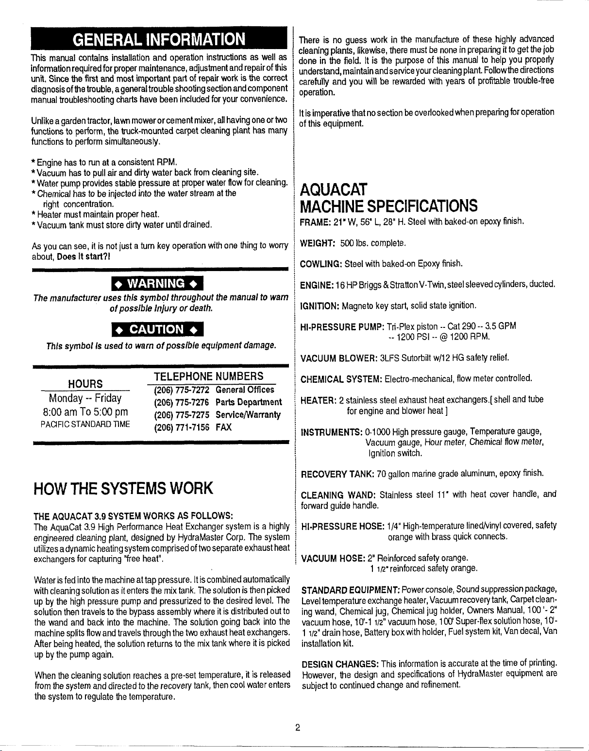
HOWTHESYSTEMSWORK
THE AQLIACAT’3,9 SYSTEMWORKS AS FOLLOWS:
The AquaCat3.9 HighPerformanceHeat Exchangersystemis a highly
engineeredcleaningplant,designed by HydraMasterCorp.The system
utilizesadynamicheatingsystemcomprisedoftwoseparateexhaustheal
exchangersfor capturing“free heat”.
Waterisfedintothemachineattappressure.Itiscombinedautomatically
withcleaningsolutionasitentersthemixtank,Thesolutionisthenpicked
up by thehigh pressurepumpand pressurizedto the desiredlevel.The
solutionthentravelstothe bypassassemblywhereit isdistributedoutto
the wand and back into the machine, The solution goingback into the
machinesplitsflowandtravelsthroughthetvmexhaustheatexchangers.
After beingheated,the solutionreturnstothe mixtankwhere it is picked
up bythe pumpagain,
Whenthe cleaningsolutionreachesa pre-settemperature,it isreleased
fromthesystemanddirectedto the recoverytank,hen cool waterenters
the systemto regulatethetemperature,
WEIGHT: 500Ibs.complete.
COWLING: Steelwith baked-onEpoxyfinish.
ENGINE:16HPBriggs&StrattonV-Twin,steelsleevedcylinders,ducted.
IGNITION: Magnetokeystafl, solid stateignition.
HI-PRESSUREPUMP:Tri-Plexpiston--Cat290-- 3.5 GPM
--1200 PSI --(Q1200 RPM.
VACUUM BLOWER: 3LFSSutorbiltw/12HGsafetyrelief.
CHEMICAL SYSTEM: Electro-mechanical,flow metercontrolled.
HEATER: 2stainlesssteel exhaustheatexchangers.[shellandtube
for engineand blowerheat]
INSTRUMENTS:0-1000Highpressuregauge,Temperaturegauge,
Vacuumgauge, Hourmeter,Chemicalflowmeter,
Ignitionswitch.
RECOVERYTANK: 70 gallonmarinegradealuminum,epoxyfinish.
CLEANING WAND: Stainless steel 11” with heat cover handle, and
forwardguide handle,
HI-PRESSUREHOSE: 1/4”High-temperatureIinedvkrylcovered,safety
orangewithbrassquickconnects.
VACUUM HOSE:2“ Reinforcedsafetyorange.
1 It? reinforcedsafetyorange.
STANDARDEQUIPMENT Powerconsole,Soundsuppressionpackage,
Leveltemperatureexchangeheater,Vacuumrecoverytank,Carpetcleaning wand, Chemicaljug, Chemicaljug holder,OwnersManual,100’-2
vacuumhose, 10’-11/2”vacuumhose,1CQ’Super-flexsolutionhose,10-
1 1/2”drain hose,Batteryboxwithholder,Fuelsystemkit,Vandecal,Van
installationkit.
DESIGNCHANGES:This informationis accurateat thetimeof printing,
However, the design and specificationsof HydraMasterequipmentare
subjectto continuedchangeand refinement.
2
Page 5
PIACEMENTOFUNIT
INVEHICLE
THEREARETWO RECOMMENDEDUNITPLACEMENTS:
A.SIDEDOOR:Mostinstallationsaresidedoor,Thisprovidesrearaccess
for accessoriesandhosesaswell asunobstructedaccessto componenff
workingsideofmachine,thusmakingitabiteasiertoperformmaintenance
and/orrepairwithoutremovingunit fromthe truck,
B.REARDOOR:Althoughthislocationpartlylimitsworkingaccess,itdoes
directthenoiseawayfromthecleaningsite. Somecleanersinthecolder
areaspreferthis locationbecauseit puts the weight massover the rear
wheelsfor bettertractionin iceandsnow,Rearmountingrequiresthe unit
tobeslidtotherightsideasfaraspossible.l%isnotonlyprovidesadequate
workingspaceon the componentside of the unit but alsomakes better
weightdistributioninsidethe van (engineand componentweightline up
overdriveshaft).Also,itisphysicallyeasierto load unit into reardoordue
to heightofvan bed,
Ensure that machine is well secured to the floor of van with hardware
supplied. Sudden or crash stop willcause machine to sliderlmvard,,.. all
500 /bs.worth!Protect yourself and the machine. SECURE lTI
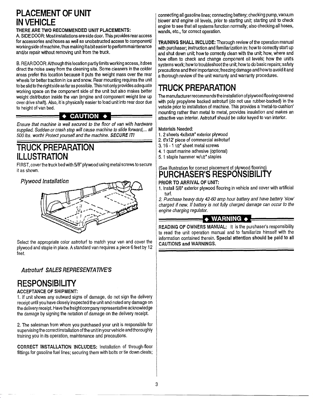
TRUCKPREPARATION
[ILLUSTRATION
FIRST,coverthetruckbedwith!Y8”plywoodusingmetalscrewstosecure
it asshown.
PlyWoo
connectingallgasolinelines;connectingbattery;checkingpump,vacuum
dower and engineoil levels, prior to startingunit; startingunit to check
mgine toseethat allsystemsfunctionnormallfi alsocheckingallhoses,
wands,etc.,for correctoperation,
TRAININGSHALL INCLUDE:Thoroughreviewofthe operationmanual
NWpurchaser;instructionandfamiliarizationin:howto correctlystartup
andshut downunit howto correctlycleanwith the unit how, whereand
how often to check and change component oil levels; how the unit’s
systemswork;howtotroubleshoottheunit howtodobasicrepairs;safety
precautionsandtheirimportance;freezingdamageandhowto avoiditand
athoroughreviewofthe unitwarrantyandwarrantyprocedures.
TRUCKPREPARATION
Themanufacturerrecommendstheinstallationofplywoodflooringcovered
withpoly propylene backedastroturf (donot use rubber-backed)in the
vehiclepriorto installationof machine,This providesa ‘metal-to-cushion’
mountingratherthan metal to metal,provides insulationand makesan
attractivevan interior.Astroturfshouldbe colorkeyedto vaninterior.
MaterialsNeeded:
1.2 sheets4x8x5B”exteriorplywood
2.flxl 2’piece ofcommercialastroturf
3.16-1 lPMsheetmetalscrews
4.1 quart marineadhesive(optional)
5.1 staple hammerwh’z” staples
Seeillustrationfor conectplacementof woodfloorin
lWRCHASERISREsPckIBILii
PRIORTOARRIVAL OF UNIT
1.Install5/8” exteriorplywoodflooring invehicleand coverwithartificial
turf.
2, Purchase heavy duty 42-60amp hour battery and have battery Wow’
charged if new, If baltery is not fully charged damage can occur to the
engine charging regu/ator.
Selectthe appropriatecolor astroturfto match your van and cover the
plywoodandstapleinplace.Astandardvanrequiresa piece6 feetby 12
feet.
AstrohIti SALES REPRESENTA7%’E’S
RESPONSIBILITY
ACCEPTANCEOF SHIPMEN’E
1. If unit showsany outwardsigns of damage, do not sign the delivery
receiptuntilyouhavecloselyinspectedthe unitandmotedanydamageon
thedeliveryreceipt.Havethefreightcompanyrepresentativeacknowledge
the damageby signingthe notationof damageon thedeliveryreceipt.
2. l%e salesmanfrom whomyou purchasedyour unit is responsiblefor
supervisingthecorrectinstallationoftheunitinyourvehicleandthoroughly
trainingyouin itsoperation,maintenanceand preca~”ons,
CORRECT INSTALLATION INCLUDES: Installation of through-floor
fittingsforgasolinefuellines; securingthem withbottsortie downcleats;
READINGOF OWNERSMANUAL: It is thepurchasers responsibility
to read the unit operation manual and to familiarize himself with the
informationcontainedtherein.Special attention should be paid to all
CAUTIONSand WARNINGS.
3
Page 6
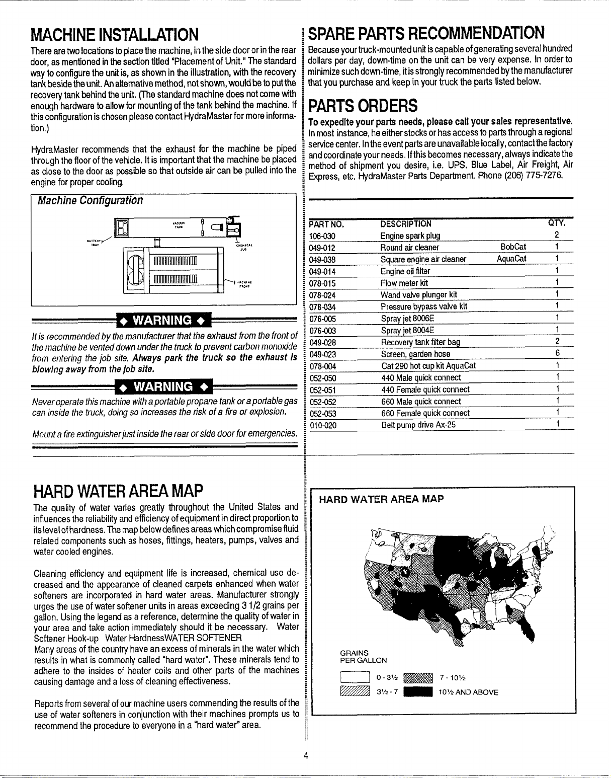
MACHINEINSTALLATION
Therearetwolocationstoplacethemachine,intheside door or intherea
door,asmentionedinthesectiontitled “Placementof Unit,”Thestandart
waytoconfiguretheunitis,asshown in theillustration,with therecove~
tankbesidetheunit.Analternativemethod,notshown,wouldbetoputttv
recoveqftankbehindtheunit.(Thestandardmachinedoes notcomewftl
enoughhardwaretoallowformountingofthetank behindthe machine.I
thisconfigurationischosenpleasecontactHydraMasterfor moreinforms
tion,)
HydraMasterrecommendsthat the exhaust for the machine be pipe{
throughthefloorofthevehicle.Itis importantthat the machine be place{
ascloseto thedoor aspossibleso that outside aircan be pulledintoth[
engineforpropercooling.
Machhe Configuration
;PAREPARTSRECOMMENDATION
?causeyourtruck-mountedunitiscapableofgeneratingseveralhundred
JIlarsper day,down-timeon the unit can bevery expense, Inorderto
inimizesuchdown-time,itisstronglyrecommendedbythemanufacturer
atyou purchaseand keepinyourtruck the partslistedbelow.
Jexpedite your parts needs, please call your sales representative.
Inmost instance,heeitherstocksorhasacce~stopartsthr~ugharegional
servicecenter.Intheeventpartsareunavailablelocally,contactthefactory
andcoordinateyourneeds,Ifthisbecomesnecessary,alwaysindicatethe
methodof shipment you desire, i.e. UPS. Blue Label, Air Freight,Air
Express,etc.HydraMasterPartsDepartment.Phone(206)775-7276.
/t is recommended by lhe manufacturer that the exhaust from the front c
the machine be vented down under the truck to prevent carbon monoxid,
from entering the job site. Always park the truck so the exhaust/.
blowhrg away from the job site.
Never operate thismachine withaportable propane tank oraportable ga
can inside the truck, doing so increases the risk of a tire or explosion.
Mount afire extinguisher just inside the rear or side door for emergencies
HARDWATERAREAMAP
The quality of water varies greatiy throughout the United States ant
influencesthereliabil”~andefficiencyofequipmentindirect proportiontf
itslevelofhardness,Themapbelowdefinesareaswhichcompromiseflui[
relatedcomponentssuchashoses,fittings, heaters, pumps,valvesan~
watercooledengines.
108-030 Enginespark plug
049-012
049438
049-014
078-015 Flow meter kfi
078-024 Wand valve plur
078434
076-005
0764)03
049-028
$9-023
784Q4 Cat 290 hot cup kit AquaCat
52-050
57-051
.. .. .
52452
52-053 660 F
1rmxl
.- ---
Round air cleaner
Square engine air cleaner
Ermine oil filter
ngerkit
Pressurebypassvaive kti
Spray jet 8006E
Spray jet 8004E
Recove~ tank filter b:
Screen, garden hose
440 Male auick conn~
Female quid connect
440
660 !
We quick connect
‘emale quick connect
Rdtrmmo driie Ax-25 1
--.. r-...r
—
ag
,,,,,-”.
HARD WATER AREA MAP
BobCat
AquaCat
2
1
1
1
1
1
1
1
1
2
6
1
f
1
1
1
Cleaningefficiency and equipmentlife is increased, chemical use de
creasedand the appearanceof cleaned carpets enhancedwhen wate
softeners are incorporatedin hard water areas. Manufacturer strongl
urgestheuseofwatersoftenerunits inareas exceeding31 /2 grainspe
gallon.Usingthe legendasa reference,determinethe qualityof wateri!
your areaand take actionimmediatelyshould it be necessary. Wate
SoftenerHook-up WaterHardnessWATERSOfTENER
Manyareasof thecountryhaveanexcessof mineralsin the waterwhicl
resultsinwhat is commonlycalled“hard water”,These mineralstend t[
adhere to the insides of heater coils and other parts of the machine
causingdamageand alossof cleaningeffectiveness.
Reportsfromseveralofourmachineuserscommendingtheresultsofth
useof watersoftenersin conjunctionwith their machines promptsust
recommendthe proceduretoeveryonein a “hardwater” area.
GRAINS
PERGALLON
~] 0-3/2 H 7-10/2
- ~/,-i’ _
10%ANDABOVE
4
Page 7
START UP
1,
Performdaily/periodicmaintenanceasspecifiedinthis OwnersManual
(page36).
2. Connectall requiredhoses.
3. Connectcleaningtool tolength ofhose requiredto performcleaning.
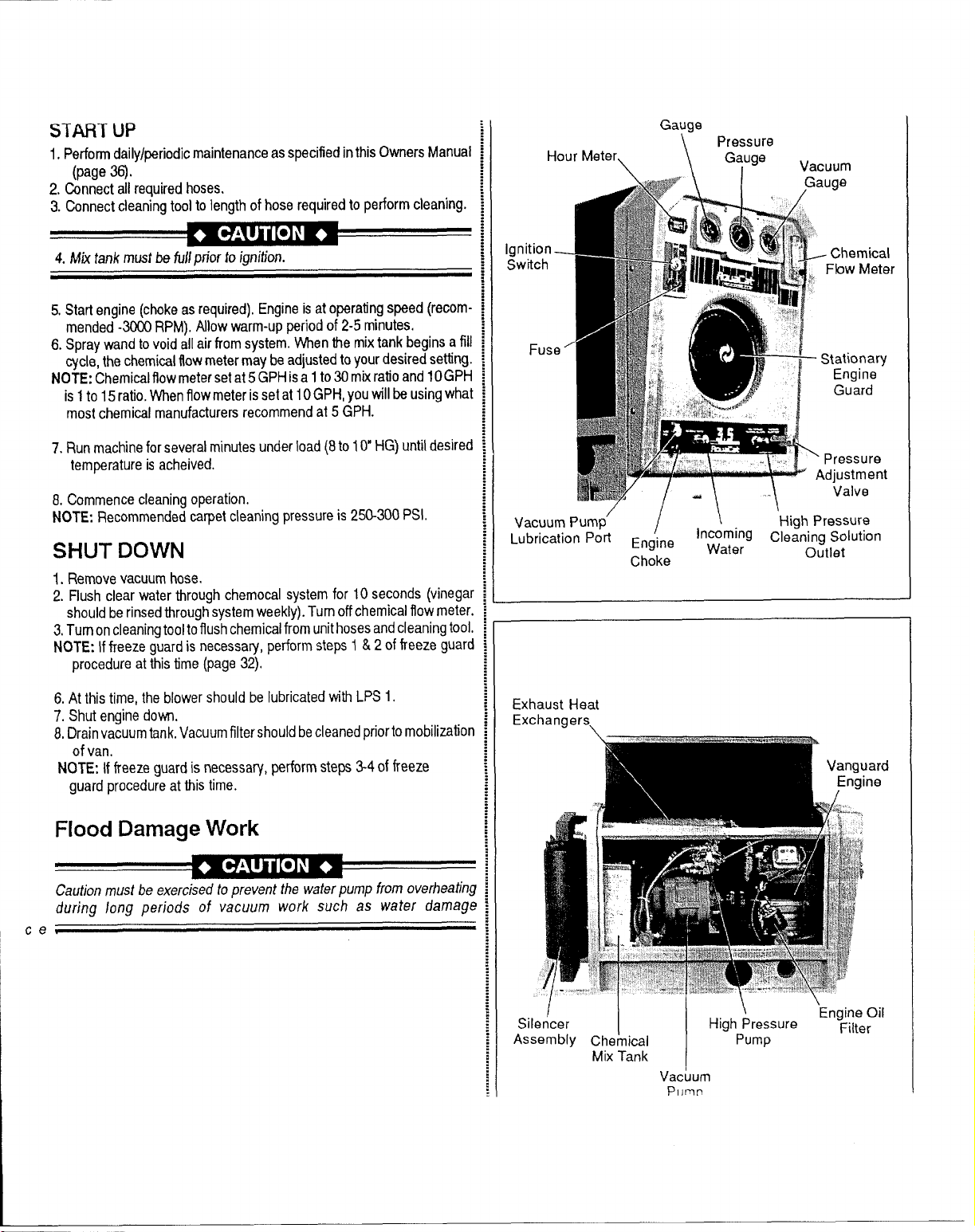
Hour Meterl
Gauge
Pressure
\
Gauge
\
.JM#%#\ 1
Vacuum
,Gauge
4. Mixtank musfbe fullm’iortoiar?ition.
5.Startengine (chokeasrequired),Engineis atoperatingspeed (recommended-3000RPM).Allowwarm-upperiodof 2-5 minutes.
6. Spraywandtovoid allairfromsystem.Whenthe mixtankbeginsa fill
cycle,thechemicalflowmetermaybeadjustedto yourdesiredsetting.
NOTE:Chemicalflowmetersetat5GPHisa 1to 30mixratioand 10GPH
is 1to 15ratio.Whenflowmeteris setatIOGPH, you will beusingwhat
mostchemicalmanufacturersrecommendat 5 GPH.
Run machine for severalminutesunderload(8to10“ HG)until desired
7.
temperatureisacheived.
& Commencecleaningoperation,
NOTE: Recommendedcarpetcleaningpressureis 250-300PSI.
SHUT DOWN
1. Removevacuumhose.
2. Flushclear water throughchemocalsystem for 10 seconds (vinegar
shouldberinsedthroughsystemweekly).Turnoffchemicalflowmeter.
3.Turnoncleaningtooltoflushchemicalfromunithosesandcleaningtool.
NOTE: Iffreezeguardis necessary,performsteps1 &2 offreeze guard
procedureatthis time(page32)
6.At thistime, the blowershouldbe lubricatedwith LPS1.
7. Shutenginedown.
8.Drainvacuumtank.Vacuumfiltershouldbecleanedpriortomobilization
of van.
NCITE;Iffreezeguardis necessary,performsteps 3-4offreeze
guardprocedureatthis time.
gnition _
Switch
Fuse
## X?//...
‘7/-\\
Vacuum Pump’
‘Lubrication ‘on Engine
Choke
Exhaust Heat
Exchangers,
; Stationary
:\
Pressure
Adjustment
Outlet
Engine
Guard
Valve
!!
:’1
..,
&
i~
Incoming
Water
High Pressure
cleaning Solution
Flood Damage Work
Caution must be exercised to prevent the water pump from overheating
during long periods of vacuum work such as water damage
\
ce
/
Silencer
Assembly Chemical
I
Mix Tank
Vacuum
Pomn
\
High Pressure
Pump
\
Engine Oil
Filter
Page 8
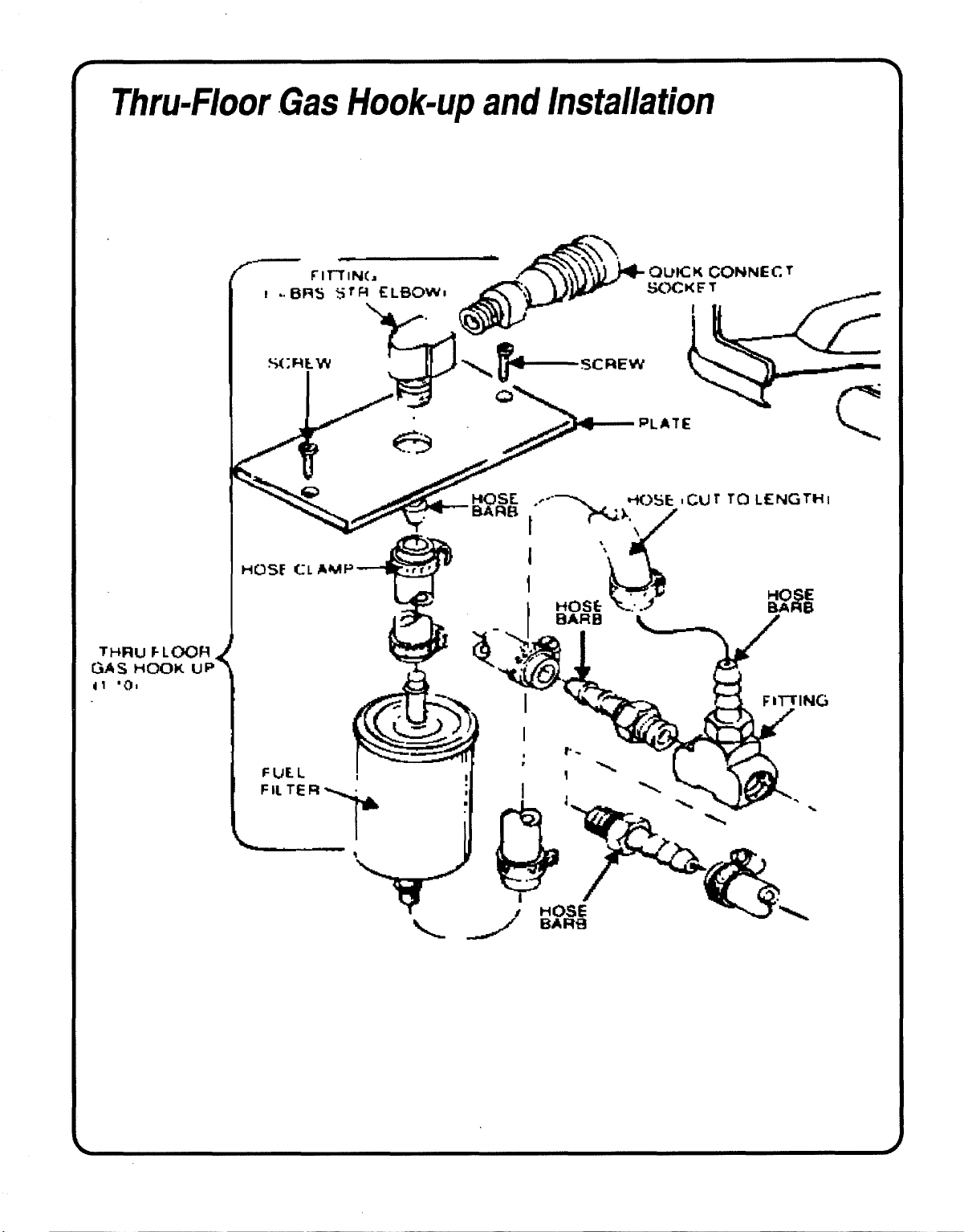
ThrwF/oor Gas Hook-up and Installation
-c.-.
1’
Page 9
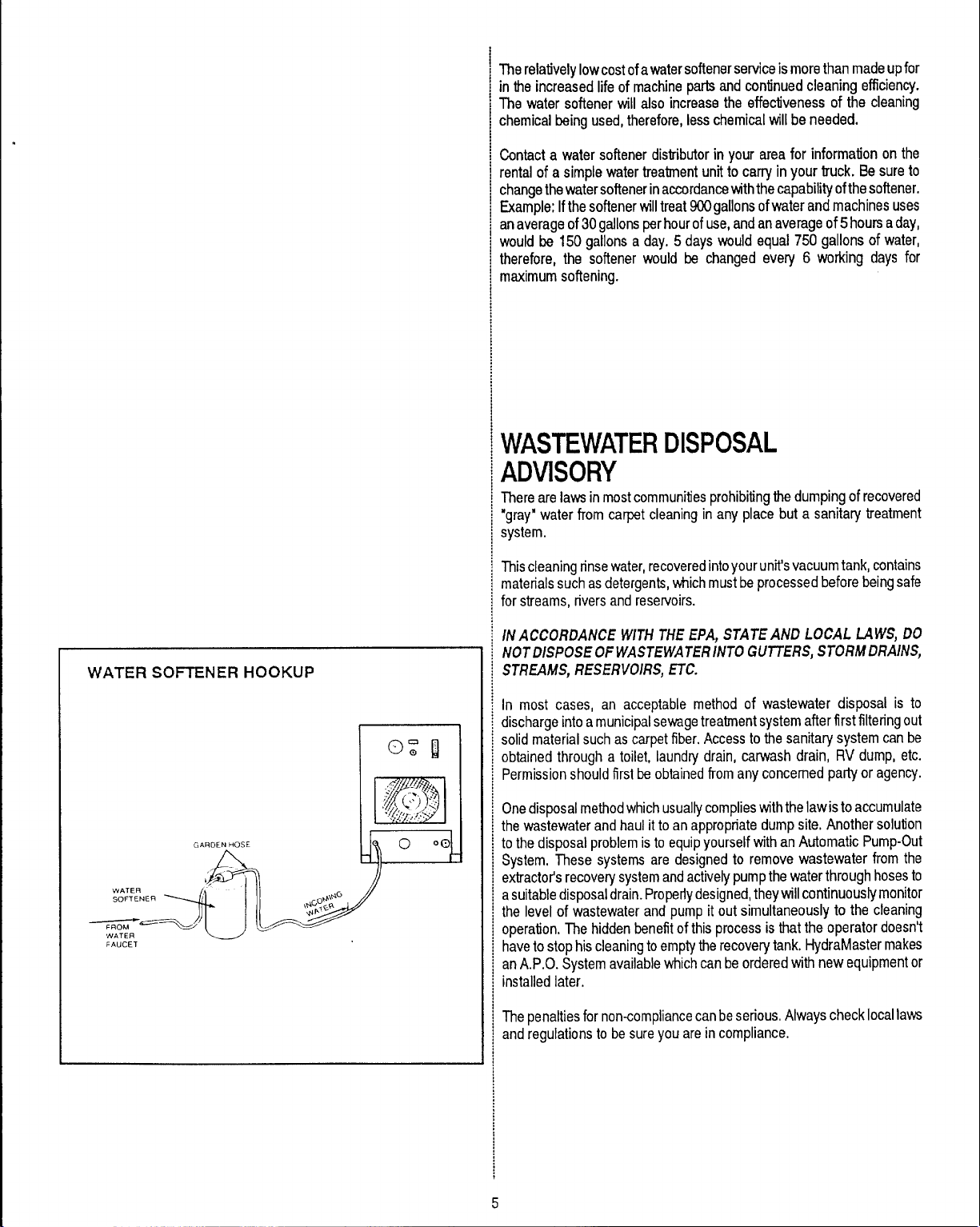
TherelativelyIowcost of awater softenerserviceismorethan madeupfor
in theincreasedlife of machinepartsand continuedcleaningefficiency.
The water softener will also increasethe effectivenessof the cleaning
chemicalbeingused,therefore,lesschemicalwillbe needed.
.
Contacta water softenerdistributorin your area for information onthe
rentalof a simple watertreatmentunitto carry inyour truck. Be sureto
changethewatersoftenerinaccordancewiththecapabilityofthesoftener.
Example:IfthesoftenerwilltreatWOgallonsofwaterandmachinesuses
anaverageof30gallonsperhourofuse,andanaverageof 5hoursaday,
would be 150 gallonsa day, 5 dayswould equal 750 gallons of water,
therefore, the softener would be changed every 6 worldng days for
maximumsoftening.
WASTEWATERDISPOSAL
ADVISORY
Therearelawsinmostcommunitiesprohibitingthedumpingofrecovered
“gray”water from carpetcleaningin any place but a sanitarytreatment
system.
WATER SOFTENER HOOKUP
GAROkN HOSE
,., -
,&
‘1
Thiscleaningrinsewater,recoveredintoyourunit’svacuumtank,contains
materialssuchasdetergents,whichmustbeprocessedbeforebeingsafe
for streams,riversand reservoirs.
IN ACCORDANCE WITHTHE EPA, STATE AND LOCAL LAWS, DO
NOTDLSPOSE OF WASTEWATER INTO GUTTERS, STORM DRAINS,
STREAMS, RESERVOIRS, ETC.
In most cases, an acceptable method of wastewater disposal is to
dischargeintoamunicipalsewagetreatmentsystemafterfirst filteringout
solidmaterialsuchas carpetfiber,Accesstothe sanitarysystemcan be
obtainedthrough a toilet, laundrydrain, carwash drain, RV dump, etc.
Permissionshouldfirstbeobtainedfromanyconcernedpartyor agency.
OnedisposalmethodwhichusuallycomplieswiththeIawis toaccumulate
thewastewaterandhaul itto anappropriatedump site. Anothersolution
to thedisposalproblemisto equipyourselfwithanAutomatic Pump-Out
System, These systemsare designedto remove wastewater from the
extractor’srecoverysystemandactivelypumpthewaterthroughhosesto
asuitabledisposaldrain.Properlydesigned,theywillcontinuouslymonitor
the level of wastewaterand pumpit out simultaneouslyto the cleaning
operation,Thehiddenbenefitof thisprocessis thatthe operatordoesn’t
haveto stophiscleaningtoemptytherecoverytank. HydraMastermakes
anA.P,O.Systemavailablewhichcanbeorderedwith newequipmentor
installedlater,
Thepenaltiesfornon-compliancecanbeserious.Alwayschecklocallaws
andregulationsto besureyouarein compliance,
Page 10
MACHINEADJUSTMENTS
Although this unit has been factory adjusted, it may require additional
adjustmentsto achieve optimum performance;i.e. attitudemay require
carb adjustment and ambient temperatures may require heat control
adjustment.Whenrequired,consult anauthorizedrepresentative.
ENGINECOOLING
Units employing air cooled engines musinot be enclosed within a van with
doors and windowsclosed. Excessive temperatures within the engine will
r~ult in premature engine failure and a compromise of applicable war-
ranty,
LEVEL OPERATtON
Dunhg operation, van or trailer must be parked on level ground not to
exceed + or -10’. F~”lure to insure proper leveling may prevent proper
internal /ubricetion of engine, vacuum arroYorhigh pressure components,
FREEZEPROTECTtON
Mother nature gives litf/e warning as to her cold spelk. Therefore,
protecting thisequipment from freezing willsave costly down-time, Placing
electric heaferin the truckor parking the truck indoors, wi//he/p to insure
an
against
freezing.
WATER/CHEMICALFLOWOPERATION
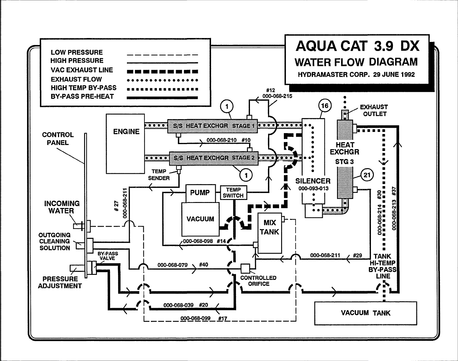
This electro-mechanicalsystem has been designedto be simple and
troublefree. IncomingwaterflowsfirstthroughtheSolenoidControlValve
(1)(seeillustrationonnext page)andthe lowpressureChemicalInjector
(2)whichare both mountedonthe exteriorofthe mix tank. As thewater
passesthroughthe ChemicalInjector,itisautomaticallyproportionedwith
a predeterminedquantityofdetergent.The MixTank(3)is equippedwith
twodifferentfloatswitches,theWaterLevelFloat(4)respondstothelevel
inthe tankandwill maintainthepropervolumeof solutionto be resewed
forthewaterpump.Thesecondary,LowWater Floatswitch(5)isasafety
switchthat isdesignedto protectyoursystemfromsuddenorunexpected
lossof watersupp~. If,for example,thewatersourceatthe housewere
turned off, the water level of the mix tank would drop, activating the
secondaryswitch,which automaticallydisengagesthe systemand pre-
ventsthe waterpumpfrom runningdry.
Thedesiredchemicalinjectionratiomaybeobtainedbyanadjustmentof
theChemicalFlowMeter(6)duringthefillcycleofthemixtank.Watermust
be flowing into the mix tank in order to adjust the chemical mix. The
chemicalwill flowfrom theChemicalJug (7)to theChemicalFlowMeter,
thentothe ChemicalInjectorwhereit is proportionedintothe MixTankat
thedesired chemicalsetting.
NOTE: Wih this unique chemical system,the chemicalflow is proportionedonly duringthe filling cyclesofthe MixTank,notduringthe direct
sprayingofthewand,Therefore,itispossiblethatasyourwandisspraying,
youmayhavenochemicalflow,Also,theconverseistrueinthatyoumay
not be sprayingyour wand, but if the mix tank is in a filling cycle,your
ChemicalFlowMeter maybe activeatthe desiredflowrate.
HOTSURFACES
During the operation of this equipment many suriaces on the machine will
become veryhot, When near the van foranyreason care must be takennol
to /ouch any hot surface,such as heater, engine, exhaust, etc.
NOSMOKING
It is unsafe to smoke in or around the vehicle.
MOVINGPARTS
Never touch anypari of the machine that is in motion, severe bodily injury
may result.
CARBONMONOXIDE
77risunitgenerates toxic fumes, Position the vehicleso thatfhe rl.imes will
be directed A WAY from the job site.
DO NOT PARK where exhausf fumes can enfer a bui)ding through open
doors or windows, air conditioning unifs or kifchen fans.
TOXICFLUMES
Do not occupy the vehicle when the cleaning equipmentis opera fing, Toxic
fumes may accumu/afe inside a stationary vehic/e.
The chemicalproportioningsystemwillmix chemicalwithwaterat a 1to
ratio when the Flow Meteris setat 5GPH,ora 1to 15ratiowhenthe
30
FlowMeter isset at 10 GPH.
nextpage)
@nliwes,
9
Page 11
AQUACATWATERFLOW
Atthis pointintheflow,solution(waterwithchemical)willnowbesiphoned
from the bottomof theMixTankto the inletoftheWater Pump(8),In the
pump the water is pressurizedand then dischargedthrough a rubber
pulsationhose downto the pressurereliefvalve (9), Fromthe pressure
reliefvalvethewaterisautomaticallydistributedtothecleaningwand and
bypassedbackto the mixtank,dependingon water usageat the wand.
Asthewatertravelsbacktowardthe mixtankfromthepressurereliefvalve
it flows through two exhaust heat exchangerswhich heat the cleaning
water.
CHEMICALSYSTEMMAINTENANCE
The chemical lines may needto be flushed withvinegar periodicallyto
prevent abnormal chemical build-up. This flushing may be done by
removingtheclearplastichosefromthe ChemicalJugandinsertingitinto
a one quartcontainerof vinegar.This shouldbedonewiththe Chemical
Flow Metersettingon 10 GPHandthe Water Heater‘off”. Simplyspray
waterfromthewanduntilthequartofvinegarisexhausted,therepeatthe
process with one quart of clear water to void all lines of vinegar.
CHEMICALTANK
TROUBLESHOOTINGGUIDE
PROBLEM:Llttieor nochemicalflow
Sotution
Check that hoses at tie Mix Tank (3) are secure. Check that the hose from the top
of the Flow Meter(6)tothe ChemicaJInjector(2)issecurewith no kinks or
leaks. Chad that the adjustingcap onthe side of the injector is notscrewed
alithe way in.Check the sls checkvalve insidethe injectorfor chemical buikf-
up and proper operation. Check the hosefrom the bottom of the Flow Meter
to the Chemical Jug (7’)for kinks, crad(s, or bubbles.
Checkthescreen ontheendofthehose whiihgoe.sintothe Chemical Jug.Tocheck
tMs screen for properfunction,remove itfrom the plastic hose. Ifyou cannot
b!ow through i$ then rinse itout with vinegar.
Check the Chemical Flow Meter (6) for obstructionsor a sticking float.
Is incoming water pressure iess than 30
Cracked or defective Chemical Flow Meter (6)?
Check the fiiter semenin the SolenoidContioi Valve (1).
PROBLEM: inabiiity to adjust chemical with tie Flow Meter
Solution
Debrii lodgedbehindteflon seatin flow Metervaive.
Teflon seat on the valve stem maybe loose. If deteriorated, repiaca O-Ring.
Insufficient water pressure. Locate new source.
PSI?
Page 12
LOW PRESSURE
HIGH PRESSURE
VAC EXHAUST LINE
EXHAUST FLOW
HIGH TEMP BY-PASS mm=mmmmmmmmnnaam
BY-PASS PRE-HEAT
CONTROL
PANEL
INCOMING
WATER
1
———
OUTGOING
CLEANING
SOLUTION
!k
, I&= L
PRESSURE u
ADJUSTMENT
,—
BY-PASS
.... ..-
——— ——— ———
-W------=
● **e*o**e ****e ● 9
SENDER
1
‘1
I
I
1
I
:::::::::................-...* .:$.+.>-..-..+..:.:.-..:?:?..:?-:.:
...............................................
............. .........
VACUUM
4
n’
/000-068-098 #14 /
#12
AQUA CAT 3.9 DX
WATER FLOW DIAGRAM
HYDRAMASTER CORP. 29 JUNE 1992
e
HEAT ~ /
EXCHGR
STG 3
i
A ooo-068-2~1 , #29
m
N
m
m
L
TANK
11-TEMP
Y-PASS
LINE
+Z r’ 00’0’’03’‘o <
.—— — ———— ———. ———— ———
L
000-088-099 #17
I
J
‘~
Page 13
PROBLEM: Mix Tank Overflows
Solution
Float switch (4) in the mix tank not moving freely, or defective.
To Check Switch: With a 12volttest Iightand the floatinthe ‘up’ position, there
should be power through the switch.
To Check Relay First, check wiring against diagram. Wti 12 volt test light
and the float switch (4)
solenoid valve. Wtth the
power at the
solenoid valve.
Solenoid valve defective: Remove solenoid valve, dsassamble and inspect
diaphragm
for cracks or tears.
in the ‘up’ position, there should NOT be power at the
float switch in the ‘down’ position, there should be
CATPUMPMODELZ9(I
OPERATINGINSTRUCTIONS
PROBLEM: Mix Tank Does Not Keep Up With Water Output
Solutlon:
Check Incoming water pressure. Check garden hose quick cannect assembly
screen.
Check garden hosesmd/orfeed hose tothe mix tankforclog,kinks or blockage.
float switch (4) inmix tank hanging up (notmoving freely). Check filterscreen
in Solenoid valve (1).
Products described hereon are covered by
oneor more ofthe follovnng
US. patents:3558244,3652188,3809508, 3920356,and3930756
c CAT PUMPS – A G. ●
LorelohcebO 5
CH+3W zuo. swnzerland
J&&p
CORPORATION
PO. Box LW5 MINNEAPOLIS, MN 55440
Phone (6 12) 7@0.s440 – Telex 290276
4N V CAT PuMPS INTERNATIONAL S A.*
Harmooleslraal 29 27 Slallon Inoustr,al E31ale, Fleet
B 2C4N Antwerp, Belgium
Phom (03) 237.72-24 — Telex 33947
Ph+ne (42) 21.3140 — Telex S65 160
9 CAT WMPS DEuTSCHLAND GmbH ●
RoslochIx Stmsse 9
6X0 W!es&9den-Bmrsladl, Wesl Germany
Phooe GB12.560301i2 – Telex 41 M713
PuMPS (U K) LTD ●
● CAT
Harwsh$w GU13 80Y, En.#and
PIIO,WJ F!ec,l 22o31 - Telex 85fL998
CPWJ ch
;PECIFICATIONS
,,,..,.,,.,,.,,,,,...,..,..,,..,3,5GPM(l3uM)
olume
ischargePressure..............1200PSI(83EAR)
IaximumInlet Pressure......-
PM,.,,,,,,,,.,..,,....................l2~
,.,,,.,,,,.,,,,,.,,.,.,..,...,......0.787’ (20mm)
ore
,,,,,,,,,,,.,,.,,.................0<472”(12mm)
troke
rankcaseCapacity.............10 oz. (.3L)
IletPort (l),...l ....................l/2” NPT(l/2’ NPT)
heroical Iniection Port (1),., 1/4” NPT(1/4’ NPT)
ischarge Ports (2) ....18. NPT (3/8’ Npq (1):~...2”2”NpT (1/2” NpT)
ulley Mounting
haft Diameter
,.,,..,..,,.,..,...,,.,,..,......12.1 Ibs.(5.5kg)
Ieight
,,.,,,,,.,,,.,.....Eitherside(Eitherside)
....................0.650” (16.5mm)
imensions.....l................l...
8.5to+ 40 PSI(-0.6to +2.8 BAR)
10,77”x9.06’x5,14“ (273.5x230x130,5mm)
10
Page 14
GENERALINFORMATIONFOR
CATPUMPREPAIR
Asyou removeyourdischargemanifold,there isa set of 3 checkvalves
(whichusuallyfall out duringdismantling),Ifthe surfacesofthese check
valvesaredirty,orshowsignsofchemicalbuild-up,itisprobablethatthey
wouldremainopencausingpressurelossorpulsation,Uponinspectingthe
valves,makesurethatthetetlon buttoninthevalvespringretainersareSW
intact,Also examinethe dischargemanifold,Lookfbr problemssuch as
cracks, chemical buildup or warping due to freezing. If this discharge
manifoldiswarped,itwill causethe checkvalvesto stickandwill resultin
lossof pressure,
TheCatpumpcupsareoftenthesourceofpressureloss.Uponinspection
theymayappearmeltedortorn,butoftentheywillIookgood,Replacethem
anyway. Thereis no sure method of visually inspectingthe cups, HydraMasterrecommendschanging
cupswhetherthey lookgoodor not.
.
When restarting thepump, check tosee that there isno cylindermotion as
this will causepremature failure of the cy/inder o-rings. Center cylinder
motion can be eliminated by switching withone of the end cylinders.
SERVICINGTHEPUMPINGSECTION
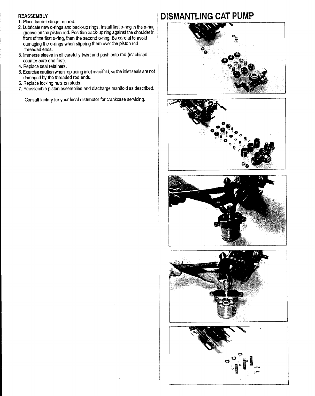
DISMANTLING
1, Removedischargemanifoldas describedinthe lastsection.
2,Slipcylindersoutofinletmanifold,NOTE: Identifycylinderssotheywill
bereplacedin theiroriginalposition(frontto back),
3. Removecotterpin,nut,andwasher.
4, Nextremovepistonretainer,spacer,and pistonassembly.
5, Removeinlet valve
Anytimeyour pump is being dismantled,HydraMasterrecommendsreplacementof ail ‘o’ ringsand seals.This is merelyaconvenienceto the
customerto makesure thatthe Catpumpis intop operatingcondition,
The Prrrrrm-A-Lubeseals locatedwithinthe intakemanifoldwill allowair
to enterthe pumpif theyareworn,Again, it is difficulttovisuallypinpoint
a defectivePrrrrrm-A-Lubeseal,Replacethemall,
RepairingofCatpumpsisnotadifficulttask. However,beforedismantling
makesureyouhavethe properpartsrequired.
1- short (orhot)cut kit 6- pistonsleeve ‘o’rings
3- Prrrrrm-A-Lubeseals
Readinstructionsthoroughly,suppliedin the Cat pumpmanual priorto
dismantlingandfollowdirectionsasstated.Oilallsealsthoroughlypriorto
installation.(Remember,anewlyscarredsealisnobetterthanoneyoujust
tookout.)
1- bottle Catoil
SERVICINGDISCHARGEVALVES
&VALVESEATS
DISMANTLING
1. Loosenthe 2 (M8)lockingnuts approximatelyoneturn.
2, Thenremovethe 2 (M8)flangenuts.
3, Graspthe dischargemanifoldwith3 fingersonthe undersideandtap
with
a softmalletto remove,
4. Valveassemblieswill remainwiththe manifold,Invertmanifoldand
dischargevalve assembliesshouldfall out,
5,Inspectdischargevalvesforwearor ridges,(Sphericalvalvesduetotheir
shapemustbe replacedwhenworn.)
REASSEMBLY
1. Placeretainerin manifoldchamber,
2. Nextinsertspringintocenterof retainer,
3, Placevalveover springwithspherical(mooned)sideup.
4, Nextinsertthe valveseat,
5, Positionmanifoldbackonto pump.
NOTE:Exercisecautionwheninsertingcylindersinto manifoldto avoid
damagingcylindero-rings,
6,Replaceflangenutsonstudsandhandtightenbothsides,Thentorque
eachsideto 125 inchpounds.
7. Handtighten lockingnut.
REASSEMBLY
1.Examineinletvalvesurfaceandreverseifdamaged(bothsidesarelap
surfaces).
2. Examinepistonassemblyfor clean inletsurface,If damaged,replace
and lubricate,
NOTECUPINSTALLATION: Wipecupinserter lightlywithoil. Slip bac-
cupring ontopiston.Forcecupover inserterandsquarew“thall
surfaces.Fauhycup installationcausesprematurefdure.
3, Nextreplacepistonspacerand retainer.
4.Slipwasher ontorod,screwon nutandtorque to 60 inch pounds.
NOTE:ALWAYS REPLACE WITH NEW C071ERPlN.
5, Examinecylinderwallsfor scoringoretching,Theseconditionswill
causeprematurewear ofyour pistonassemblies.Replaceifworn
ordamaged,
6, Lubricatecylinderand replaceo-ringsand backuprings(if defective),
7, Positioncylindersintheiroriginal orderintomanifoldchambersand
carefullyiip over rodends;nto the pump.
8.Replaceflangenutsonstudsandhandtighten bothsides,Thentorque
eachsideto 125inchpounds.
9. Handtighten lockingnuts,
SERVICINGTHESEALSANDSLEEVES
DISMANTLING
1,Removedischargemanifoldandpistonassembliesasdescribed,
2.Removeboth(M8)lockingnutsfrom studs,
3,Wtihsoft mallet,tap inletmanifoldloosefrom crankcase.
4,Placeinletmanifoldon pair ofclearance blockswith crankcaseside
downanddriveout seals,
5,Invertinlet manifoldwith CRANKCASE SIDE UP.
6. Lubricatecircumferenceofnew Prnwrn-A-Lubeseals,positionin
manifoldwith GARTER SPRING DOWN and driveinto place,
7,Examinesleevesforscoringor otherdamagebeforeremoving,
6.Ifworn, graspsleevewith pliers andpull off.
NOTE:This procedurewill marthesleeve souse onlyif sleeveis
to be replaced.
\ 9, Removeo-ringand back-upringsfrompistonrod.
Page 15
REASSEMBLY
1, Placebarrierslingeron rod,
2, Lubricatenewo-ringsandback-uprings,Installfirst o-ringintheo-ring
grooveon thepistonrod. Positionback-upringagainsttheshoulderin
flont of thefirst o-ring,thenthe second o-ring.Becarefulto avoid
damagingthe o-ringswhenslipping themoverthe pistonrod
threadedends.
3. Immersesleevein oil carefuliytwistand pushonto rod(machined
counterboreendfirst).
4, Replaceseal retainers.
5,Exercisecautionwtrenreplacinginletmanifold,sothe inletsealsarenot
damagedby thethreadedrod ends.
6, Replacelockingnuts onstuds,
7, Reassemblepistonassembliesanddischargemanifoldas described.
Consultfactoryfor yourlocal distributorfor crankcaseservicing,
DISMANTLINGCATPUMP
Page 16
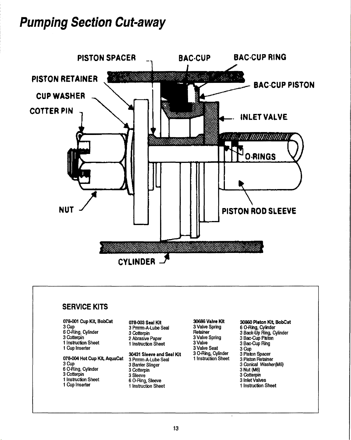
Pumping Section Cut-away
PISTON
PISTON RETAINER \
CUP WASHER
COTTER PIN
1
NUT -f
SPACER _,
BACSCUP
BAC~CUP RING
IN
PISTON ROD SLEEVE
J
SERVICEKITS
07S-001 Cup Kit BobCat
3cup
Ofling, Cylinder
6
CotterPin
3
1 Instruction Sheet
t Cup Inserter
076-004 Hot
3 cup
6 O-Ring, Cylinder
3 Cotterpin
1 Instruction Sheet
1 Cup inserter
Cup Ki$ AquaCat 3 prmm.A~u@ Sed 1 Instruction Sheet
CYLINDER Y
076-003SealKit
3Prrrrm-A.LubeSeai
3CotterPin
2Abrasive
1 Instruction Sheet
30431 Sleeve and Seal Kit
3 Barrier Siinger
3 CotterPin
3 Sieeve
6 O-Ring, Sleeve
1 instruction Sheet
Paper
13
30666ValveKit
3ValveSpring
Retainer
3 Valve Spring
3 Valve
3 Valve Seat
3 O-Ring, Cylinder
30660PistonKit BobCat
6 O-Riig,
3 Back-UpRing,Cylinder
3 Bat-Cup P~ton
3 Bat-Cup Ring
3 Cup
3 Piston Spacer
3 Piston Retainer
3 Conical Washer(M6)
3 Nut (M6)
3 Cotterpin
3 Inlet Valves
1 instruction Sheet
Cyliider
Page 17

PISTON MODEL 290 Exploded View
d
●-
‘ 57
14
Page 18

PARTSLISTMODEL290
ITEM
10
11
12
15
16 43804 Crankshaft
17 14487 Rearing
18
t9 0974107 O-Ring, oil seal case
20
21
23 101799 Connecting rod
24 101800
25
26 20017 Seal washer 3
27 147-006 Oil seal 3
28
29 097408 O-Rina. sleeve 3
30 29003
31
32 26654 Seal washer 3
33 1384)01 Seal rea”ner 3
34 25128
35
35
PARTNO, DESCRIPTION QTY.
1 20285 Ofling (Buns-N)
44274 Crankcase
2
3 156408 Stud(M8X
4 097404 O-Ring, oil tillercap
5 027-007
8 43340
43339 Crankcasa cover 1
9
074-021 Bubble oilgauge
23170 O-Ring,drainplug
25625 Drain plug 1
92520 Sems comb head screw (M6 x 20) 6
1474Q5 Oil seal (Buns-N) 2
041-021 Oilseal case 2
92519 Sems comb head screw (M6 x 16) 8
16948 Piston pin 3
25327 Barriir slinger 3
28771 O-Ring, sleeve (WOn) 3
29614 Sleeve (29743 Unchromed)
25635 Inlet man”tild - stainless steel 1
147-008 Pm’rrm-A-Lube seal 3
30325 Prrrrrm-A-Lube seal (Vrron] 3
Oil fillercap 1
O-Ring, crankcase cover 1
Piston rod 3
Back-up ring, Sleeve (Teflon)
Inlet manifold 1
82)
ITEM
1
1
2
1
1
1
1
2
2
3
3
3
38
39
40
41
39-41
39-41
42 27963
43
44
45
46
47
46
49
50 090-005
51 43442
52
53
54
56
57
58
Electric Clutch Aesembly
59 152-005
60
61 036-005
62 143464
63 174034 Flat washer (5/t6 US)
64
PARTNO.
27004
30543
0974)25 Bat-Cupring(Teflon)
044-001
43474
078401 BobCat CUpkii
0781U34
27002
27006
27000
14156 Cotterpin
0454X)4
097-012 O-Ring, cylinder (Buns-N)
11377
097~24 Bat-Cup ring, cylinder
25&4
43360 Valve spring
43723 Valve
43434 Discharge valve seal
81109 Hex nut (M8)
101804 Hex ffange nut (M8)
108403 Shaft protector
077-005 Key, electric clutch
174-018 Lock washer (5/16 US)
DESCRIPTION
Inletvalve
Bat-Cuppiston
Cup (t4ton)
Bat-Cup assembly
AquaCat cup kti
Piston spacer
Piston retainer
Conical washer - SIS(M6)
S/S(M6)
Nut -
Cylinder(43634 Unch)
O-Ring, cyIinder win)
Discharge manifold
Discharge manifold - SIS
Valve spring retainer
Tapered sleeve
6’ electric clutch
8~ mm socket head screw
Q-W.
3
3
3
3
3
1
3
3
3
3
3
3
6
6
3
1
1
3
3
3
3
2
2
1
1
1
1
1
1
1
Page 19

—
CATPUMPTROUBLESHOOTINGGUIDE
PROBLEM: Pulsatlon
Cause
-n discharge valves of pump.
Worn Prrrrrm-A-Lube seals.
Excessive temperature.
Soiution
Clean or replace discharge valves.
Replace.
Check pump solenoid.
PROBLEM:
Cause
Worn nozzle.
Belt slippage.
Air leak in inletplumbing,
Relief valve stuck, partially plugged or improperly adjusted; valve seat worn.
Inlet suction strainer clogged
Worn piston assembly. Abrasives in pumped fluid or serve cavitation. Inadequate
Fouled or ditty inletor discharge valves.
Leaky discharge hose. Replace worn valves, valve seats.
PROBLEM: Pump runs extremely rough,
Cause
Restricted inlet orair entering the inlet plumbing. Proper size inlet plumbing; check for air tight seal.
Inlet restrictions and/or air leaks, Damaged cup or stuck inlet or discharge valve. Replace worn cup or cups, clean out foreign materiel, replace worn valves.
Worn inlet manifold seals. Prrrrrrn-A-Lubes, Replace worn seals.
PROBLEM: Cylinder O-Rings biown next to discharge manifoid
Cause
Pressures in excess of rated PSI, Check for piugged nozzle, closed valves or imprope
Warped manifold. Freezing. Replace manifold.
LOWpt%SSU~
water supply,
orimproper size.
Solution
Replace nozzksof proper size.
lighten or replacw use correct belt.
Dismantle, reseal, and reassemble.
Clean and adjust relief vaivq check for worn and dirty valve seats. Kit available.
Clean. Use adequate size. Check more fraquemty.
Install properfiiter. Suction at inlet manifold must be limited to liftingless than 20
feet of water or -B.5 PSI vacuum.
Clean inlet and discharge valve assemblies.
Replace discharge hose,
prassurwis verylow
Solution
Soiution
rlyadjusted bypass valve.
PROBLEM: Leakage at the cyiinder O-Rings at the discharge manifoid and
powderysubetancein the area of the O-Ring
biack,
Cause
Loose cylinders Cylinder motion caused by improper torque on the discharge Retighten. ~nottighbntmmuch ortieemoftiemmtioidwill be~wed,causing
manifoid.
PROBLEM: Water ieakage from under the inlet manifoid
Solution
looseness in the center cylinder.
Cause Soiution
Worn iniet manifold seals. Prrrrrm-A-Lube. Leaking sleave O-Ring. installseals. If piston rod sleeves are scored, repiace sieeves and sleeve O-Rings.
PROBLEM: Oii ieak betwean crankcase and pumping section
Cause Soiution
Worn crankcase piston rodseais.
PROBLEM: Oil ieaking in the area of the crankshaft
Cause
Worn crankshaft seal or improperly instaiied oil seal, Remove oil seal retainer and repiace damaged gasket and/or seals.
Bad bearing.
Repiace crankcase piston rod seals.
Soiution
Repiace bearing.
(cmthues, nextpsge)
15
Page 20

CATPUMPTROUBLESHOOTINGGUIDE
PROBLEM Excessive play in the end of the crankshaft puliey
Cause
Worn ball bearing from excessive tension on drive beit.
PROBLEM: Water in crankcase
Cause
May be caused by humid air mndensing intowater inside the crankcase.
Leakage of manifold inlet seals and/or piston rodsleeves O-Ring.
PROBLEM: Oil leaking from underside of crankcase
Cause
Worn crankcase piston rod seals.
PROBLEM: 011 leaking at ths rear portion of the crankcase
Cause
Damaged or improperly installed oilgauge or crankcase rear cover O-Ring, and
drain plug O-Ring.
PROBLEM Oil leakage from drain plug
Cause
Loosedrain
plugor worndrainplugOfling.
solution
Replam ball bearing. Properly tension belt.
Solution
Change oil at 3 month or 500 hour intervals using Cat pump crankcase oil (other
approved oilevery month or 200 hours).
Replace seals, sleeves and O-Rings.
Solution
Replace seals, sleeve end O-Rings.
SoMion
Replace oil gauge or cover O-Ring, and drain plug O-Ring.
solution
Tighten drain plug
orreplace O-Ring.
PROBLEM: Loud knocking noise
in pump
Cause Solution
Pulley loose on crankshaft,
Broken worn bearing. Replace bearings.
PROBLEM: Frequent or premature faiiura of the inlet manifold seals
Check key end tighten set screw.
Cause So/ution
Scored rods or sleeves.
Over pressure to inlet manifold,
PROBLEM: Short cup life
Cause
Abrasive materiel in the fluid being pumped.
Excessive pressure and/or temperature of fluid being pumped. Check pressures endfluid inlettemperetur~ besuretheyare withinspecifiedrange.
Over pressure of pumps. Reduce pressure.
Running pump dry.
Front edge of piston sharp,
PROBLEM: Strong surging attheinletandlow preasureonthedischargeside
Replace rods end sleeves.
Reduce inlet pressure per kvmmtions.
Solution
Install proper filtration on pump inlet plumbing,
Do not run pump wiihout water.
Replace with new piston,
Cause Soiution
Foreignparticles intie in!etordischargevalve orworn inletand/ordischergevalves.
Check forsmooth lapsurfaces oninletand discharge valve seats. Discharge velve
seats, and inletvalve seats may be lapped on a very fine oilston% damaged
cups and discharge valves cannot be lapped but must be replaced.
16
Page 21

HIGHPRESSUREPUMP
TROUBLESHOOTINGGUIDE
PROBLEM: LOSS of D1’eSSUi’e
Qi4MWd@
1.Cloggedfilterscreen ingarden hose quick connect coupler.
A. Remove and clean or replace filter.
2. Low water pressure at sourcs.
A.Determine rate of flow end select an alternative source of supply ifwater
pressure is inadequate.
3. Defective or blocked check vatves in high pressure pump cylinder head.
A.Dismantlecylinder head andreplaceordeanapplicablecheckvalve,
4.Delaminated,kinkedorcloggedhosebetweenthemixtankandthe high
pressurepump.
5.Defectivepressurereliefvalve
h!@pressure bypassvafve isdesigned tofullyclose when thedeaningtool
isturned on. Any foreign matter collecting on the piston will prevent full
closure ofthe valve and allow a partianofthewaterta continueto circulate
instead of being routed to tie cleaning tool. To correct this situation, the
bypass valve mustbedismantled and cleaned (referto illustiationprovided
for bypass dismantling),
A. Dismantle and dean pressure relief valve as shown in illustration.
B. Replace defective or worn out bypass cup.
C, Replace bypass valve.
6. Defective or worn cups.
A. Remove endreplace piston cups as defined by pump section of this
manual.
7. Loose driie belt for high pressure pump.
A. Readjust belt as required or replace if defective.
or debris in pressure reliefvalve. NOIE: The
Bypass Valve Assembly
‘?(D”
IYPASSPARTSLIST
IEF. NO.
PART NO, DESCRIPTION
3 000-105-101
000-105-102 Piston plate: Bypass valve
4
5 000-076-101 Kfl, seal for Bypass valve
7 COO-I48-004
8 000-0974)05 O-Rirra. Bvr)ass valve fittina
Thrust date, Bvr)ass valve
Seat & O-Ring, Bypass valve
QTY,
1
1
1
1
1
INFORMATION
Thevacuum blowerincorporatedin Urismachineis a positivedisplacementlobetype,manufacturedbyCooperIndustries.Theperformanceand
lifeofthis unitis greatlydependenton the care and proper maintenance
t receives,
PROBLEM: Insufficient or excessive water flow
Cause/Solution
Wornout spray jet. NOTE: Cleaning tools designed to spray a canstant flow of
1.
11/2 GPM will average 1gallon offiowperminute inactual workingsituations
sinceflow isnoncontinuous.Anaverage fbwof 1GPM results in6000 gallons
of fbw for evey 100 hours of unit operation. Spray tips are capable of
consistent flow rates for epproximatety 20,000 gallons. They should be
replaced therefore approximately every 350 hours. Worn spray jeis albw a
greater average rate of fbw thus reduang
A, Remove andreplacesprayjet.
2. Redur%on offlow.
A. Due to increased length of solutionhose. NOTE: For every 50 feet of hose
beyond 100 feet intotal length,a measurable !css offlow is experienced. This
cond~on is a result of the increased friction experienced by the water as it
passes through the hose. Therefore, itis necwssaiyto increase the pressure
at the machine 40 PSI for every additional 50 feet of cleaning solution hose
over 100 feet.
desiredtemperaturelevels.
3ecauseof the closetolerances betweenthe lobes and housingofthe
~acuumblower,solid objectsenteringthe inlet will damagethe internal
obes,gearsandbearingordirect drivecoupler.
To preventthis, a stainless steel filter screen has been placed at the
#acuuminletinsidethevacuumrecoverytank.This stainlesssteelscreen
s fingertightandshould beremovedforcleaningweekly.
When machine is being run fortestpuposes and the vacuum inlet on top
ofmachine b open, caution should be used.
Toprotectthevacuumblowerfromoverloadinganddamagingitself,there
savacuumreliefsysteminstalledonthevactank,Whenthevacuumtank
nletiscompletelysealedoff,a maximumof12HGwillbeattained.A hole
mthetop blowerpipeelbowactsasthelubricationpoint.Attheendofeach
jay, LPS 1or Pennzguardshouldbesprayedin beforeshuttingdownthe
machine.See blower lubrication illustration, If you fail to lubricatethe
iacuum blowerdaily,rustdepositsand moisturewill decreasethelife of
thevacuumblower.
Readthevacuumblowermanualcarefullyforproperoilchangeandgrease
application.Themaintenancelogmaydifferslightlyfromthe manual,but
:hetruck-mountedcarpetcleaningmachineapplicationisverydemanding
)fthe vacuumblowerandthereforeitshouldbemaintainedmoreregularly,
MOTE: Vacuum tankisprotacted from ovetiowingbya vacuum tank, frbat
W switch. This switch is not activated by foam,only by ijquid.
17
Page 22

Blower Lube Port
Spray lubricant into blower lube port for 3to 5 seconds,
then immediatelyshutoff machine.Useonly LPS 1
moisturedisplacinglubricant,
VACUUMTANKFILTERBAGS
HydraMasterfilter bags are designedto trap all of the lint, that would
normallycollectatthebottomofyourvacuumtank.The useofthesebags,
ifemptiedatthe endofeachjob, will eliminatetie build-upof muchof the
debrisinthetank.
the incomingdirtywater inlet~nke vacuum~~k. -
to
To reorderbagsusepart number049-028.
Vacuum Tank Filter Bags
PROTECTIV
HOLDING RECOVERY
The drawstring top of these bags is designed to b tied
R
TANK
Vacuum Flow
S/S Fil
Vacuum
Relief
Vacuu
Kill Swi
ag
Page 23

VACUUMBLOWERTROUBLESHOOTINGGUIDE
PROBLEM:
Cause solution
Collapsed
Cloggedstainless steel finer,
Defective vacuum tank seal.
Defectiveor“open”vacuumtankdumpvafve.
Fracturedwekfonvacuumtank.
Collapsed or kinked vacuum hose.
Pluggedvacuumhose.
Restiiclion in cleaning tool.
Worn end plates or lobes in vacuum b!ower.
Defectivereliefvalve.
PROBLEM:Blower Isseized
Cause
Rust.
Foreignmatter.
Note: Theabovementioned, rust foreignmatterandseizing areoftencaused from
Loss of pressure
vacuum hose between blower and vacuumtank. Remove and replace hose. NOTE: A special reinforcxxfhoseisrequired
for replacement.
Remove end clean or replace stainless steel filter.
Removeand replacevacuumtank seal.
Closevalve,
Replacevalve.
Re-weld as required or replace tank.
Reshapehose if possibleand/oreliminatekinks.
Remove obstructionsbyreversingthevacuumhose.
Remove obstruction.
Replaceworncomponents.NOTE:Mustbeaccompliihedbyaqualifiedtechnican.
Inspectand replaceifnecessary.
Solution
Sprayrustdissolvinglubricantonto lobesto emulsifyrustandattempt to rotate
vacuumlobes.
Dismantfeandremoveforeign mattarand repairas required.NOTE:Dismantling
mustbeaccomplishedbyqualifledtechnican.
foamLwvehrgthroughthe Mower.
PROBLEM:NoiseIn vacuum blower
Cause
Worngears.
Lackoflubrication.NOTE:Permanentdarnagemayhaveresultedfrom lack
of lubrication.
Wornbearings.
Debrisand/orforeignmaterialbuild-up.NOTE:A stainlesssteelfilter isprovided
in vacuuminletlocatedin vacuum blower components.
Lcoseormissingmountingbofts.
Solutlon
Removeandreplacegears.NOTE:Replacementofgearsmustbeaccomplished
byqualifiedtechnican.
Timing of vacuum blowerhas beenchanged dueto worncomponents.NOTE:
Replacementofcomponentsmustbeaccamplihed byqualifiedtechnican.
Lubricateasspecifiedbyapplicablevecuumblowermanual.SeeTableofContents.
Removeand replace bearings as required. NOTE:Must be acmmplished by
qualifiedtechnican.
Dismantfevacuumblowerandremoveforeignmaterial.NOTE:Ilsmantfingshould
beaccomplishedby quafifi+s-dtechnicanonty.Replacementofwornpartsis
necessary.
or reinstallmounting bofts.
Tighten
Page 24

VACUUMBLOWERWARRANTY
COOPERwarrantsproductsofitsmanufacturetobefreefromdefectsinmaterialandworkmanshipifproperlyinstalled,maintained,andoperated
undernormalcondtiionswith competentsupervision.
Noperson,agent,representativeordealeris authorizedtogiveanywarrantiesonbehalfofCOOPERnortoassumeforCOOPER anyotherliability
in connectionwithany of COOPERSproducts.
Thiswarrantyshallextendfortwo (2)yearsfrom dateof installationprovidedthis equipmenthas beenput into servicewithin six monthsafter
shipmentfromtheCOOPERfactory,IfrepairsorreplacementsaremadebythePurchaserWithoutCOOPER’Spriorwrittenconsent,COOPER’S
warrantyshallceaseto beineffect. No allowancewillbegrantedfor anyrepairsor alterationsmadebythe PurchaserwithoutCOOPER’Sprior
vwittenconsent,
Machinery,equipmentand accessoriesfurnishedby COOPER,but manufacturedbyothers, arewarrantedonly to the extentof the original
manufacturer’swarrantyto COOPER,
COOPERagreesatitsoptionto repairatthe pointofshipmentortoreplacewithoutchargef.o,b.pointofshipment,anyparl orpartsofproducts
of COOPER’Smanufacture,whichwithinthe specifiedwarrantyperiodshallbeprovedto COOPER’Ssatisfactiontohavebeendefectivewhen
shipped,providedthe PurchaserpromptlynotifiesCOOPER,inwriting,ofsuch alleged defect
COOPER’Sliabilityto Purchaser,whetherincontractorintori arisingoutofwarranties,representations,instructions,ordefectsfromanycause
shallbe limitedto repairingor replacingofthe defectivepartor partsasaforesaid,f.o.b, pointof shipment.
NoliabilitywhatsoevershallattachtoCOOPERuntilsaidproductshavebeenpaidfor, EXCEPTASSTATEDINTHISSECTIONANDINTHE
PRECEDINGSECTION TITLED ‘WARRANTY’AND EXCEPTAS TO TITLE, THERE ARE NO GUARANTEEDOR WARRANTIESOF
MERCHANTABILITY,FITNESS,PERFORMANCEOROTHERWISE,EXPRESS,IMPLIEDORSTATUTORY,AND COOPERSHALLHAVE
NOLIABILITYFORCONSEQUENTIAL,INCIDENTALOROTHERDAMAGES,HOWSOEVERCAUSED.
DATEINSTALLED
MOD~
COOPER/GARDENER-DENVER1800GardenerExpway Quincy,IL 62305-4024
VACUUMBLOWERLUBRICATION
At the gear end the timing gear teeth are lubricatedby being partially
hoursor moretlequentiy ifinspectionso indicates,The oildrainplugis
at (C),
submerged,Thegearteethserveasoilslingersfor gearendbearings.At
the driveendofthe bearingsaregreaselubricated.
NOTE:Olderunitsmayhavetheoilfilllevelanddrainholeslocatedinthe
castirongearcaseinsteadofinthe headplate.Bearingsondriveendof
FILLING PROCEDURE
Removesquareheadventedoilfillplug (A)on gearend. Removeoillevel
plug(B)locatedinthe headplate.Fill gearcaseuntiloildripsoutofthe oil
levelhole(B),Uselubricantsaslisted.Addfreshoilasreuuiredtomaintain
blowerrequiregreaselubricationevery100hoursofoperation.Bearings
which requiregrease lubricationwill have a greasefitting (D)at each
bearing.Whenregressing,the oldgreasewillbeforcedoutof the vents
duringoperation,Topreventdamagetoseals,theseventsmustbekept
properle~el:Theoil should bedrained,flushedand replacedevery300 ~ open}t all times. -
Vacuum Blower Motor Lubrication
‘In ●pplicstiorts with extreme variations. in
qnbiertt t.rnpwsture 8 20W - 50W multtplc
wscosi
-LOWER DISCHARGE
SERl~
;!
SAE10W
n)” SAE40
Uw ZVJ- F
/**C*PI
w 011ISracommend~d.
FOR GREASE LUBRICATED BEARINGS
Ssrviccsverv 600 hours of oporstion
TEMPERATURE
-400 to 275*
(-4@ to
12rPc)
SAE50
F
6;:A~E
B-=ri
45
200
250
TVPE
ng.Groins
20
Page 25

INTHEINTERESTOFSAFETY
BEFORE STARTING ENGINE,READ AND UNDERSTAND
THE “OPERATING AND MAINTENANCE INSTRUCTIONS. ‘
OPERATINGANDMAINTENANCE
INSTRUCTIONSFORMODELSERIES
303400(16HP)
#+
@
A
,...................................Read Operator’s Manual
..............................,!...!.
..................................!.
..!!..,,.,,...............,,,,,....!.
B
Warning/Caution
oil
Fuel
THIS SYMBOL M&4NS WARNING OR CAUTION.
DEATH, PERSONAL lNJURYAND/OR PROPERWDAMAGE
A
MAY OCCUR UNLESS INSTRUCTIONS ARE FOLLOWED
CAREFUUY.
[WARNING: Do NOT...
1A
1, DONOTrun engine in an enclosedarea,Exhaustgasescontaincarbon
monoxide,an odorlessanddeadtypoison.
2,D0 NOTplacehandsor feetnear movingorrotatingparts.
3,DO NOTstore,spill,or usegasolinenearan open flame,or devicessuch
as astove,furnace,or waterheaterwtich usea pilot light ordevices
whichcan createaspark
4.DO NOTrefuel
refueling is preferred.
NOTfill fueltankwhile engineis running,Allowengineto coolfor
5.DO
2 minutesbeforerefueling.Storefuel in approvedsafetycontainers.
NOT remove fuel tank capwhileengineis running.
6,DO
NOT operate engine when smellof gasolineis presentor other
7.DO
explosiveconditionsexist.
8,DO NOToperateengine ifgasolineis spilled.Movemachineawayfrom
thespill andavoidcreatingany ignitionuntilthe gasolinehas evaporated.
9.DONOTtransportenginewith fuel in tank.
10.DONOTsmokewhenfilling fueltank.
11,DO NOT choke carburetor to stop engine. Whenever possible,gradually
reduceenginespeed beforestopping.
12.DONOTrun engineat excessivespeeds.This mayresult ininjufyt
13.DONOTtamperwith governorsprings,governorlinksor otherpatis
whichmay increasethe governedenginespeed.
14.DONOTtamperwiththe enginespeedselectedbythe original
equipmentmanufacturer.
15,DONOTcheckforspafi withspark plug or spark plug wireremoved.
Usean approvedtester.
16.DONOTcrankenginewith sparkplugremoved.If engineisflooded,
placethrottlein
17.DONOTstrikeffywheelwitha hardobjector metaltool asthis maycause
flywheelto shatterinoperation.Usepropertoolsto serviceengine.
18,D0 NOToperateenginewithouta muffler,Inspectperiodicallyand
replace,ifnecessary.If engineisequippedwith muffferdeflector,inspect
periodicallyand replace,ifnecessary,with correctdeflector.
19.DONOToperateenginewithan accumulationof grass, leaves,dirt or
othercombustiblematerialinthe mufflerarea,
20. DONOTusethis engineonanyforest covered,brush covered,orgrass
coveredunimprovedland unlessa sparkarresteris installedonthe
mufffer,The arrestermustbemaintainedin effectiveworkingorderby
theoperator.In theState ofCaliforniathe above is requiredby law
(Section4442of the CaliforniaPublicResourcesCode).Otherstates
mayhavesimilarlaws. Federallawsapplyon Federallands,
21,DONOTtouchhot muffler,cylinder,orfins becausecontactmay
indoors where area is not well ventilated, Outdoor
“FAST” position and crank until enginestarts.
A
. .. . .. ,.,,.,.,..,..,.,.....AirCleaner......Air Cleaner
,.
.:.
Q
21
Page 26

WARNING: DO
1.ALWAYSDOremovethe wirefrom the sparkplugwhen servicingthe
engineor equipmentTO PREVENT ACCIDENTAL STARTING.
Disconnectthe negativewirefromthe batteryterminalifequippedwith
a 12volt startingsystem.
2, DOkeepcylinderfinsandgovernorpartsfreeofgrassandotherdebris
whichcanaffectenginespeed.
3. DOpullstartercordslowlyuntilresistanceif fett. Then pullcordrapidly
to avoidkickbackandpreventhand or arminjury.
4. DOexaminemufflerperiodicallyto be sure itis functioningeffectively.
Awornorleakingmuffiershouldberepairedorreplacedasnecessary.
5.DOusefreshgasoline.Stalefuelcangumcarburetorandcauseleakage.
6. DOcheckfuellinesandfittingsfrequentlyfor cracksor leaks.Replace
if necessaty.
NOTE:UseOriginalBriggs& Stratton Service ReplacementPartswhen
servicingyour engine, Briggs& Stratton AuthorizedServiceCenters
carryastockofsuchparts.TheuseofBriggs&StrattonPartspreserves
the oriiinal designof your engine. Imitation replacementparts offer
potentialriskincludingtheriskof personalinjury.Cantactany Briggs&
StrattonAuthorizedServiceCenterfor OriginalBriggs& StrattonReplacementParts,
DFILL CRANKCASEWITH OIL
lace enginelevel.Cleanareaaroundoilfill.Removedipstick.POUR OIL
LOWLY. Fill to FULLmark ondipstick, DO NOT OVERFILL
0Ti5 Afterstartingengine,stopafter30seconds.Checkoillevelandadd
if necessary, Without filter, oil capacity is approximately 1-1/2 q~.
(48OZS.or 1,42Itrs),With oilfilter, oil capacityisapproximately1-3/4
k.
(560zs. or 1,65Itrs.
0 CHECKOIL LEV L
laceenginelevel.Removedipstickandwipe oil fromit with cleancloth.
crewdipstickintotube untilcapbottomsontube.Removeandcheckoil
vel, Dipstickmustbe firmlyscrewed intotubewhenengineis running.
2
Oii Fill and Dip Stick
BEFORESTARTING
READ THE OPERATING INSTRUCTIONS OF THE
EQUIPMENT THISENGINE POWERS.
OIL RECOMMENDATIONS
We recommenduseofahigh qualitydetergentoil “ForServiceSC,SD,SE,
SF,orSG,”suchas Briggs&Strattonhigh qualitydetergent30weight oil
(partno.1CC005),or 10W-30weight oil (partno.272001). Detergentoils
keeptheenginecleanerandretardformationofgumandvarnishdeposits.
Use no special additives with recommendedoils.
RECOMMENDEDSAE VISCOSITYGRADES
*
**
.20 0
‘F
‘c -30
* UseSAE30 oilin hightemperature,high loadapplications.
w 10W-40oil maybesubstitutedif 10W-30is not available.
* Use synthetic oil having 5W-20, 5W-30 or 5W-40 viscosity, If not
.20
TEMPERATURERANGEANTICIPATEDBEFORENEXTOILCHANGE
available,a petroleum-basedmulti-grade oil may be used having
5W-20 or 5W-30viscosity.
20 40 60 80
-lo 0
10
20 30
100
40
Engine Components
1,Air Cleaner
2. FuelShut-offValve
3. Carburetor
4. RewindStarter
5. BlowerHousing
6, OilDrain Plug
r-d
7,12 Veil ElectricStarter
8, Model,Type and
CodeNumbers
9, SparkPlug
10,ValveCover
Fuel Tank (Optional)
11,
NOTE:Using multigradeoils (5W-20, 5W-30, 5W-40,and 10W-30)will
increaseoil consumption.Check oil level more frequently when using
them.
22
Page 27

FUELRECOMMENDATIONS
Carburetor Ao’justment Screws
Thisenginewilloperatesatisfactorilyonanygasolineintendedforautomo- ‘
tive use. A minimum of 85 octane is recommended.DO NOT MIX OIL
W/Tf-l GASOL/NE.
I
Useclean,fresh,lead-freegasoline,We recommendtheuse of Briggs&
StrattonGasolineAdditive,partno.5041.Purchasefuelinquantitythatcan
beusedwithin30days.This willassurefuelfreshnessandvolatilitytailored
tothe season,Leadedgasolinemaybe usedif lead-freeis notavailable.
Useof lead-freegasolineresultsin fewercombustiondepositsand longer
valvelife,
NOTE: We DO NOT recommend the use of gasoline which contains
alcohol, such as gasohol.
MUST NOT contain more than 10 percent Ethanol and MUST be \
removed from the engine during storage. DO NOT use gasoline i
contain-
ing Methanol.See STORAGEINSTRUCTIONS(page27),
DO/vC)7’REMOVEfuel~ while engineisrunning. DO ~O~~lLL fuelfank j idje stop, turn idle mi~ure screw W clockwise (lean)untilspeed~
topointofoveflowing. A1/owapproximately 1/4 in. (5mm) of tank space for ~
tiel expansion.
However,if gasolinewith alcoholis used, it ~
I
I
\ FINALADJUSTMENT
~Start engine and place equipmentspeed controlin ‘IDLE” or “SLOW
~position.Hold carburetorthrottle lever againstidle stop and adjust idle
~speedscrewtoobtain1300to1500RPM.Stillholdingthroffleleveragainst
~ startstoslowandthenWcounterclockwise (rich)untilenginejuststarts
~to slow.Finally,turnscrewto midpointbetweenrichand lean.
--l
IDLE
SPEED
SCREW
I
IDLE
MIXTURE
SCREW
/
~ng~fle Co~~Ofle~ts
12.Fuel Pump
13, Dipstick
14,Exhaust Manifold1
15.Crankshaft
16.Oil Filter
17,Air Cleaner
CARBURETORADJUSTMENTS
Minor carburetor adjustment may be required to compensate
encesinfuel,temperature,altitudeorload.Aircleanerandaircleanercover
mustbe assembledto carburetorwhen runningengine,
TWIN CYLINDER CARBURETOR ADJUSTMENT IS UNIQUE.
ADJUST CARBURETOR FUEL MIXTURE IN THE ORDER STATED
AS FOLLOWS:
INITIALADJUSTMENT
Gentlyturn idlemixturescrewclockwiseuntilitjustcloses.Turningscrew
in too far may damage it, Then turn idle mixture screw 1-1/2 turns
counterclockwise.This initial adjustment will permit the engine to be
startedandwarmedup(approximately5minutes)priortofinaladjustment.
for differ-
adjust idle speed screw to obtain 1200 RPM, if governed idle spring
~Now
~isred,or900 RPM,ifgovernedidlespringisvhite. Releasethrottle lever,
If engine does not accelerate smoothly, readjust idle mixture screw
approximately1/8turncounterclockwise(rich).
NOTE:Enginesoperatedataltitudesof approximately3000to 5000fee
(900to1500meters)orhighermayrequiretheinstallationofahighaltitude
carburetormainjet to achievebestengineperformance.Ifematicperfor-
manceisobserved,contacta Briggs&StrattonAuthorizedServiceCenter
for ahigh altitudejet.
Governed Idle Spring
I
GOVERNED IDLE SPRING
(RED OR WHITE)
d
/
EXHAUST MANIFOLD =
23
Page 28

TO PREVENT ACCIDENTAL STARTING when servicing the engine or
equipment, always remove sparkplug wires from sparkplugs. Disconnect
negative wire from battery terminal ifequipped wlh 12voltstarthgsystem.
Toservicecartridue:
a. Removeknobandcover plate,
b. Removecartridgeand cleanbytappinggentlyonflat surface.
c. Ifvery dirty,replaceorwash in a non-sudsingdetergentandwarm
water solution, Rinsethoroughlywithwater from insideout until
water
runsclear. Letcartridgedrythoroughlybeforeusing,
CHECKOILLEVELREGULARLY Checkaftereach8hoursof
operationor daily, BESUREOIL LEVELISMAINTAINED.
CHANGE OIL AS RECOMMENDED
Change oil after first 8
operatingconditionschangeoil afterevery50hoursof operationoreverv
season, ‘tiichever occu~ first, Change‘oil eve~ 25 hours if engine is
operatedunderheavy loador athighambientairtemperatures.Remove
oil drain plug and drain oil while engine is warm. Replace drain plug.
Removedipstickandrefillwithnewoilofcorrectgradeandweight.Replace
dipstick,
CHANGEOIL FILTER
Replaceoilfilterafterevery10Ohoursofoperationoreveryseason,which
ever occurs first.Beforeinstallingnewfilter,Iightlyoilfiltergasketwithfresh
clean engine oil, Screw filter on by hand until gasket contacts oil filter
adapter,Tighten1/2to 3/4turn
for oil leaks,Recheckoil leveland addoil if reauired.
hours of operation. Thereafter, under normal
more, Starl and run engineatidletocheck
Oil Filter/ 011Drain ,
Petroleum solvents, such as kerosene, are not to be used to clean
cartridge. They may cause deterioration of the cartridge. DO NOT OIL
CARTRIDGE, DO NOT USE PRESSURIZED AIR TO CLEAN OR DRY
CARTRIDGE.
d. Reinstallcartridge,coverplate,knobandpre-cleaner,
2, Reinstallaircleanercoverand reattachclipstosidesofaircleanerbody.
Round Dual Air Cleaner Element
R
OIL /
DRAIN
OIL PART NO.=
FILTER
I
491056 ~
AIRCLEANERMAINTENANCE
SERVICE AIR CLEANER
Removeand servicefoam pre-cleanerevery25 hoursor every season,
whicheveroccursfirst, Servicepapercartridgeevery1(Xlhours oreve~
season,whicheveroccursfirst,
NOTE:Serviceair cleanermoreoften underdustyconditions.
f?OUNDDUAL ELEMENT
1, Unhookclips on bothsidesof aircleanerand removecover.
To servicepre-cleaner:
a, Slidefoam pre-cleaneroff cartridge.
b, Washit in liquiddetergent andwater.
c. Squeezeit dry ina clean cloth,
d, Saturateit in engineoil, Wrapit inclean, absorbentcloth and
squeezeto remove EXCESSoil,
e, Reinstallpre-cleanerover cartridge,
f, Reinstallair cleanercover andreattachclipstosides of air
cleanerbody.
Square Dual Air Cleaner Element
T
24
Page 29

$QUA&llUAL
ELEMEN~
1.Loosenknobandremovecoverassembly,
2. Removecartridgeand pre-cleanerfrom cover,
To service me-cleanec
a, Washpre-cleanerin liquiddetergentand water,
b, Squeezeit dry ina clean cloth,
c.Saturateitinengineoil.Wrap it in clean,absorbentclothand
squeezeto removeall EXCESS oil.
To service cartridae:
a. Cleanbytappinggently onflat surface,
b, Ifverydirty, replaceorwash in a nonsudsingdetergentand
warmwatersolution,Ilnse thoroughlywithwaterfrominside
outuntilwater rumsclear, Letcartridgedrythoroughly
beforeusing.
Petroleum solvents, such as kerosene, are not to be used to clean
cartridge, hey may uruse deterioration of the cartridge, DO NOT OIL
CARTRIDGE. DO NOT USEPRESSURIZEDAIR TO CLEAN OR DRY
CARTRIDGE.
Reinstall pre-cleaner in cover with foam toward cover.
3,
4, Reinstall cartridge in cover with tabs on cartridge in slots in cover.
Reinstallcoverassemblyonair cleanerbody,
5,
CLEAN ENGINE
Remove dirt and debris with a cloth orbrush, CleaningwitA aforcefulspray
ofwaterisnotrecommendedaswatercouldcontaminatethefuelsystem,
CLEAN ROTATINGSCREEN(ELECTRICSTART ENGINES)
ORREWINDSTARTERGARD
Brushgrass,chaffanddirtfromrotatingscreenor rewindstartergarddaily
(moreoften ifneeded)to preventenginedamagecausedbyoverheating
and/oroverspending,
LEAN COOLINGSYSTEM
rass,chaffordirt
may clog the rotatingscreenandtheaircoolingsystem.
very100hoursoreveryseason,Whicheveroccursfirst,removetheblower
xrsing andcleanthe areashownto preventoverspeeding,overheating
ld enginedamage,Clean moreoftenif necessary.
Coding System
CLEAN AREAS
OF ALL DIRT
LEAN SPARKARRESTERSCREEN
engine muffler isequipped with spark arrester screen assembly, remove
rery 50 hours or every seasonfor cleaningand inspection.Replaceif
amaged,Contactany6riggs & StrattonAu~horizedServiceCenter.
~EPLACESPARK PLUGS
Spark Plug ,
,76 mm(.030 m.) ~
I
Toassuresrncmth operation, keep governorcontrols and linkage clean and
free of debris.
Periodically clean mfier area to remove all grass, dirtand combusf-
ible debris,
-7.
. .
eplace every 100 hours of operation or every season, whichever
ccursfirst,
OTE:Donotblastcleanspati plugs,Sparkplugs shouldbecleanedby
:rapingor wirebrushingand washingwith a commercialsolvent.
parking cannot occur if wire termira/ does not fit firmly on spark plug.
!eform termina/ if necessary.
/ REPLACEFUEL FILTER
i ReulaceIn-Linefilter evervseasonor moreoftenif required.Contactany
iggs & StrattonAuthori~edServiceCenterfor correctreplacement. -
Fuel Fjlter
I
25
Page 30

ENGINEMAINTENANCESCHEDULE
Followthe hourlyorcalendarintervals,whicheveroccurfirst, Morefrequentservicemaybe required.
Changeoilafterfirst 8 hours,thenafterevery 50hoursoreveryseason,
Note 1:Changeoil every25 hourswhen operatingunderheavyloador in highambienttemperatures,
Note2 Clean moreoftenunderdustyconditionsorwhenairbornedebris is present.
BRIGGS& STRATTONAUTHORIZEDSERVICECENTERSAREREADYTO SERVEYOU AND COMMlllED TO QUALITY SERVICE.
26
I
Page 31

GENERALINFORMATION
ABOUTENGINE
Thisisatwincyiinder,overheadvalve,aircooledengine,Alldrilled/tapped
holes and fasteners on this engine are ISO metric. However, where
equipmentattachesto engine,SAE standardsapply.
Onmobileequipment,thisenginewilloperatesatisfactorilyatanyangleat
operator and equipment can function safely,
which
STORAGEINSTRUCTIONS
I
Enginesto be storedover 30days needto be protectedor drainedof
fuelto prevent gum from forming in the fuel system or on essential
1
mrburetorparts.
i. Forengine protection,we recommendthe useof Briggs& Stratton
GasolineAdditive, PartNo,5041,availablefrom anyBriggs&
StrattonAuthorizedServiceCenter,MixAdditivewithfuelinfueltank
orstoragecontainer.Runenginefir a shorttimeto circulateAdditive
throughcarburetor,Engineandfuel canbestored up to 24 months.
MODELSERIES290400,294400 & 303400
.............................................................2.W in, (68 mm)
Bore
Stroke,.............................0....................1..0..0.
Disriacement
Ho~epower ,.,,.,,.............................,..!,!,,......
RPM
Horsepower,.................................................
RPM
Home~wer ..................................................3OMW
RPM
,,,..................................!,..,....,.
2.60in. (66 mm)
29,3cu. in. (480cc)
290400
294400
12”HP d 3600
3600
3600
MODELSERIES350400
.,.,..,......................................................2.83 in. (72mm)
Bore
..,.,,.,..,,.,,,,,,,,,,,,,,,.,,.,.......,..,,,,,.,,.,,.,.,.2.76in, (70mm)
Stroke
Displacement................................................
Horsepower
NOTE:Forpracticaloperation,thehorsepowerloadingshouldnotexceed
85%ofthis rating.Enginepowerwill decrease3-1/2%for each1,000feet
(305m)abovesealeveland1%foreach 109F(5.tYC)above77’ F (25QC).
TUNE-UPSPECIFICATIONS
DESCRIPTION
Air CleanerPre-cleaner(round)
Air CleanerCartridge(round),...................................,!.,,!..
Air CleanerPre-Cleaner(square)...................................... 805113
Air ~eaner Cartridge(square)...........................................
Air CleanerPre-cleaner(withfuel tank) .............................271794
Air CleanerCartridge(withtiel tank).................................393957
FuelFilter (withoutfuel pump)...........................................
FuelFilter (withfuel pump)
Oil Hlter...........................................l......................o.........491056
ResistorSparkplug (ChampionRC 12YC)........................ 4910E6
NOTE:Walkingtingerslogoand“Yellowpages”areregisteredtrademarks
invariousjurisdictions.
CLEARANCES
SparkPlugGap..,..,...................................... .030in. (.76mm)
IntakeValve*,,.,,,,,,,.,,.,,.,..............................
ExhaustValve*..............................0..............
*Check whenengine iscold,
In some areas, local law requires the use of a resistor spark plug to
suppress ignition signals. If an engine was originally equippedwith a
resistor spark plug, be sure to use the same type of spark plug for
replacement.
.,,..,.,,.,.,,,.,,................................
....................................,..,,
.,,,,,,,,,,..................................!..
34,7cu. in. (570cc)
18 HP@3600RPM
B&S PARTNO.
271271
394018
805267
298090
394358
DIMENSION
,004-036 in. (.1O-.l5mm)
,004-,006in, (,1O-,15rnm)
If Additive is not used or if engine is operating on gasoline containing
alcohol, remove all tiel from tank end run engine until if stops from lack
of fuel.
2.Whileengineisstillwarm,drainoilfromcmnkcase.Refillwithfreshoil,
3, Remove spark plugs and pour approximately 1 ounce (30 ml) of
engineoil intoeachcylinder, Replacesparkplugs andcrankslowly
to distributeoil.
4,Cleandirtandchafffromcylinders,cylinderheadfins,blowerhousing,
rotatingscreenandmufflerareas.
SERVICE& REPAIRINFORMATION
If service or repair is needed,contact a Briggs & StrattonAuthorized
ServiceCenter.Toserveyou promptiyandefficiently,aServiceCenter
will needmodel,type andcode numbersfrom yourengine.
YournearestServiceCentermay belocatedin the
“YellowPageY’directoryunder“Engines,Gasoline,”
“Gasoline Engines,”orsimilar category.Youmay also
locatethe ServiceCenterinyour mailingzip codearea
m
AuthorizedServiceCenterscarrya stockof Original Briggs&Stratton
ServiceReplacementPartsandareequippedwithspecialservicetools.
Askfor anduse~ originalBriggs &StrattonServiceReplacement
Parts which preserve the original design of your engine. Imitation
replacementpartsofferpotentialrisksininternalconstructionaswellas
fit,finishandwarrantyback-up,Trainedmechanicsofferexpertservice.
Majorenginerepairsrequirepropertools andathoroughknowledgeof
internal combustionengine repair procedure.
Briggs&Strattonpublishesillustratedshop
manuals,partslists andowner’smanuals
for every engine it manufactures.To receivealistofavailablepublications,writeto
Briggs & Stratton Corporation,P,O, Box
1144, Milwaukee, WI 53201, Attention:
ServiceDivision.Theshop manualshown
hereincludes“TheoriesofOperation,”com-
mon specificationsand detailed information coveringthe adjustment,tuneupand
repairof Briggs&StrattonOHV,twincylin-
der, 4 cvc~- ermines and is available from anv Brictgs& Stratton
Authori~ed
order directiyfrom the factoryat the above address,Requestmanual,
PartNo. 272144.
by calling: 1-800-233-3723.There areover30,000
.W AuthorizedServiceCentersworldwideavailableto
.W1
serveyou,
‘Service
Center.
Yoti
‘~an also
27
Page 32

ABOUTTHEWARRANTYONTHE
VANGUARDENGINE
If warrantyserviceis needed,contactyour nearestAuthorizedBriggs&
StrattonService Center,For prompt attention,your Centerwill need to
knowthe enginemodel,typeandcodenumbers,thetroubleexperienced
andthetotal numberof hoursthe enginewas run.
BRIGGS & STRA’ITON WARRANTY COVERS ONLY DEFECTIVE
MATERIAL AND/ORWORKMANSHIP.
Briggs& StrattonCorporationwelcomesthe opportunitytomakejustified
warranty repairs by any of its Authorized Service Centers. In most
instances,the requestsfbr warranty repair are handled in a quick and
routinemanner.However,somerequestsforwarrantyarereceivedwlich
appearnot justified. Inthese cases, thoughengine ownersmay not be
awareofit, theprematurefailure oftheirenginewascausedby abuseor
neglect,ortheequipmentonwhichitwasmounted,ratherthantheengine,
Ifyoudifferwith thedecisionofyour ServiceCenter,investigationwill be
madeto determinetheapplicabilityofwarranty.Askthe ServiceCenterto
submitall supportingfactstotheFactoryfor review.Ifthe Factorydecides
that your claim is justified, you will be fully reimbursedfor those items
accepted as defective. To avoid misunderstandingwhich might occur
betweenengineownersandAuthorizedBriggs&StrattonSewiceCenters,
we listbelowsomeof thecausesof enginefailurethat Briggs&Stratton
warrantydoesnotcoverfor repairor replacement.
LIMITEDWARRANIY
FORVANGUARDENGINES
“Fortwoyearsfromdateof purchase,Briggs&StrattonCorporation
w“llreplacefor theoriginalpurchasers,free ofcharge,anypart, or
partsoftheengine,founduponexaminationbyanyFactoryAuthorizedServiceCenter,orbythe FactoryatMilwaukee,Wisconsin,to
bedefectiveinmatenalorworkmanshiporboth.Thisistheexclusive
remedy,
“For’fiveyearsfromdateof purchase,Briggs&StrattonCorporation
will replacefur theoriginalpurchasers,freeof charge,anypart,or
partsofthe MAGNETROhK@IgnitionSystem(excludingthe spark
plug),founduponexaminationbyany FactoryAuthorizedService
Center,or bythe Factoryat Milwaukee,Wisconsin,to bedefective
in materialor workmanship,or bolh, so as to result inthe loss of
ignition,Thisis the exclusiveremedy.
“All transportation charges on parts submitted for replacement
under this Wamantymust be borne by purchaser, For warranty
servicecontactyournearestAuthorizedServiceCenteraslistedin
the‘YellowPages’under‘Engines,Gasoline’or‘GasolineEngines.’
THEREISNOTOTHEREXPRESSWARRANTY,IMPLIEDWAR-
RANTIES, INCLUDINGTHOSE OF MERCHANTABILITYAND
FITNESS FOR A PARTICULAR PURPOSEARE LIMITED TO
ONEYEARFROMPURCHASEANDTOTHE EXTENTPERMITTED BY LAWANY ANDALL IMPLIEDWARRANTIESAREEX-
CLUDED,LIABILl~FORCONSEQUENTIAL DAMAGESUNDER
ANYANDALLWARRANTIESAREEXCLUDEDTOTHEEKENT
EXCLUSIONIS PERMllTED BY L4W.
Somejurisdictionsdo notallow limitationson howlong animplied
warrantylasts,andsomejurisdictionsdonotallowthe exclusionor
limitationof incidentalor consequentialdamages, so the above
limitationand exclusionmay notapplyto you,This warrantygives
you specificlegalrightsandyou may alsohaveother rightswhich
varyfrom jurisdictionto jurisdiction.”
Briggs&StrattonCorporation
F.P,Stratton,Jr.
Chairmanand ChiefExecutiveOfficer
Page 33

WARRANTYPERIOD
ENGINES
CONSUMERUSF
tion
COMMERCIALUS13
tion
*For purposesofthiswarrantypolicy,“consumeruse”shallmeanpersonal
residentialhouseholduse by the original retailconsumer, “Commercial
use” shall mean all other uses, including use for commercial, income
producingorrentalpurposes.Oncean enginehasexperiencedcommercialuse,it shallthereafterbeconsideredas acommercialuseenginefor
purposesof thiswarrantypolicy.
- Lifetimelimitedwarrantyofthe Magnetronignitionshallcoverpartsand
laborfor the firstfive (5)yearsftom thedate of purchase;thereafteronly
parts, “Lifetime” shall mean lifetime of the engine in the hands of the
originalpurchaser,
- Appliesto equipmentretailed inthe U.S.A.and Canada.In all other
com#i:Ethe warrantyfor CONSUMERUSEis thesameas COMMER-
.........................All Vanguardand l/Cengines.
.,..,.,,.,,2 year-engine Ltietimew-Magnetrorv13igni-
........2 year-engine Ltietime*-Magnetrorx10igni-
andre-oilthe aircleanerregularly.
6,Damageorwearcausedby gritfrom blastcleaningsparkplugs is not
coveredbyWananty,Wedonotapproveofcleaningsparkplugsonan
abrasiveblastcleaningmachine,sincegritcan remainintheplug,and
laterenterthe engine.
7.Warrantydoesnotcoverthetune-uporadjustmentofan engineunless
theneedforsuchrepairisthe resultof defectsin materialorworkmanshiporboth.Ifequipmentisassembledandadjustedbytheowner,the
engineoperatingandmaintenanceinstructionsaresufficientlyclearto
permittheaverageownerto makeminoradjustments.Such minor
adjustmentsare NOTcoveredbyWarraniy,
8, Brokenparts,which result from excessivevibrationcaused by loose
engine mounting,loose cutter blades, blade unbalance, improperly
attachingequipmentto engine crankshaft,overspendingor abusein
operation,are notcoveredbywarranty.
9,Repairoradjustmentofassociatedpartsorassembliessuchasclutches,
transmissions,remotecontrols,etc.,whicharenotofBriggs&Stratton
manufacturewill notbe coveredby Briggs& StrattonWarranty,
10,Only ORIGINALBriggs&Strattonparts,or partsapprovedbyBriggs
&
Strattonmaybecoveredby Warranty.
NO REGISTRATION (WARRANIY) CARD IS NECESSARY TO
OBTAIN WARRANTY ON BRIGGS & STRATTON ENGINES.
SAVE YOUR PURCHASERECEIPT. PROOFOF PURCHASE DATE
andauthorizedBriggs&S~attonservi~eaccounts,wearelis~ngsomeof
thecausesofenginefailure,whererepairorreplacementisNOTcovered
by Brlggs & Stratton warranty.
NORMALWEAR:
Warrantywill notcoverrepairwherenormaluse hasexhaustedthelifeof
apart orengine,Engines,likeallmechanicaldevices,needperiodicparts
replacementandserviceto performwell.Itshouldberememberedthatthe
servicelife of any engine is dependenton the care it receives andthe
conditionsundervhichit hastooperate,Someapplications,suchastillers,
trashpumps,rotaymowers, areveryoftenused industyordirtyconditions,
whichcan causewhat appearsto be prematurewear, Suchwear,when
causedby dirt, dust,spark plugcleaninggrii or other abrasivematerial,
which hasenteredthe engine becauseof impropermaintenance,is not
coveredby Wamanty.
ABUSE ORNEGLECT
1.Bentorbrokencrankshafts:Suchdamageisnormallytheresultofabuse,
such as strikinga solid objectwith the cutter bladeon a rotary lawn
mower,andis notcoveredbyWarranty,
2, Enginerepairsrequiredfromthe useof contaminatedorstalefuel are
not
‘coveredbvWarrantv,Suchfailureswouldincludestickingvalves,and
carburetor andfue~pipeswtich are cloggedbygum d~positswhich
formthroughthe useof stalefuel. Always usecleanfresh
regulargasoline.
3.
Partswhich are scored or broken becausean engine was operated
withoutsufficient lubricatingoil, the proper gradeof lubricatingoil or
contaminatedlubricating oil are not coveredby Warranty.Check oil
level at leastevery five hoursand refill whennecessary.Changeoil
at recommendedintervals,
Damagecaused by overheating or overspeedingis not covered by
4,
Warranty,Overspendingor overheatingoccurs ifthe coolingfins becomepluggedwithdirt, grassordebris, or if an engineis operatedin
a confinedarea without sufficientventilation.Cleanfins on thecylinder,cylinderheadandflywheelregularly,
5, Damageor wear causedby dirt which entersthe engine becauseof
improperaircleaner maintenanceis notcoveredby Warranty,Clean
WARRANTYIS AVAILABLE ONLY THROUGH SERVICECENTERS
WHICH HAVEBEEN AUTHORIZEDBY THE BRIGGS & STRATTON
CORPORATION.YOUR NEAREST SERVICE CENTER IS LISTED
IN THE YELLOW PAGES OF YOUR TELEPHONE DIRECTORY,
UNDER‘ENGINES, GASOLINE” OR “GASOLINE ENGINES.”
29
Page 34

Seeenginesectionof thismanualbginning on page21to assistyouin
resolvingenginerelatedproblems.
PROBLEMS:
ENGINEFAILSTO START
ENGINERUNSROUGH
ENGINEBACKFIRES
ENGINEFAILSTO ACCELERATE
ENGINEREDUCESSPEEDTO LOWRPMUNDERLOAD
B.DefectiveCarburetororgas leakage.
A, Cleancarb,
B, Replacecarb,
C.Choke lockedin closedposition,
D. When replacing tielpump insure that it is the same
pressure rating recommended by manufacturer.
CAUSESAND/ORSOLUTION:
1. Lossof fuel.
A. Emptygastank.
B, Pluggedfuel lineor filter.
C, Defectiiefuel pump(Replacewithmfg.suggestedreplacement
partsonly),
D,Gaslinekinked,crushedor quickdisconnectinsidethetrucknot
connected.
2, Blownmasterfuse,
A, Electricalshort.
B. DefectivefUse.
3. Defectivespark plugs,
A. Removeandreplace.
B,Cleanand regap.
4, Defectivesparkplug wires,
A, Sparkplugwiresalongwith manyothersmay,at certainpoints
comeincontactwithheatedparts(exhaustmanifold)orabrasive
parts(sharpmetal,teflonhose).This maybe taken intoconsiderationforelectricalshorts.
B, Removeand replaceignitionmodule,
5. Lowcompression,
A, Defectivevalve.
B.Stuckvalve.
C,Worncompressionrings.
D, Defectivepiston.
6, Floatswitch inrecoverytankinoperative.
NOTE:Temporaryrepairpermitsdisconnectionoffloatswitchwire
betweentankandmachine,Continuedoperationwiththiscondi-
tionwill compromisevac blower.
A. Switchstuckon uprightpositionbyforeignmaterial.
B, Defectivefloat switch.
9. Improperlyadjustedcarb.
NO~: A comprehensivemanualisavailableanddefines
necessaryadjustments.
A. Incorrectairmixtureratioadjustment.
B, Incorrectfloat leveladjustment.
10.Carbonbuild-upin cylinders.
NOTE:Carbonbuild-upcanbe minimizedby usingunleaded
regulargas.Shouldcarbonremovalbenecessary,reinstall
headswithnew gaskets.
A, Carbonbuild-upmaybe excessiveifcarb, orvalvesare
improperlyadjusted,enginaRPMtoo low,improperspark
pluggap,
B.Removecylinderheadsandeliminatecarbonbuild-upwith
wire brush.
11.Incorrectignitionmoduleairgap.
A. Regapignitionmoduleto specifications.
12, Dirtyair cleaner,
A. Ifexhaustgasketsdo notseat pmpetly or heatexchanger
gasketis bad,exhaustmay heatandmeltthe air cleaner
requiringmuchclean-uprepair.
13.Cloggedfuelfilter.
A. Removeand replace.
14.Lowoil levelor malfunctioningoil pump.
A. Oilpressuresensorscan beinstalledonthe engine,Thiswill
eliminatemanyproblemswhichmayoccur.
15, Vacuumtankfull.
A, Emptyvacuumtank.
7, Enginewill notturnover,
A. Deadbattery.
B. Looseterminalconnectionon batteryor ignitionswitch,
C, Defectivestarter.
D,Seizedengineor blower.
30
Page 35

The entire electrical system operates on 12 volts DC which is provided by NOTE: When new battery is installed insure it is properlychargedbefore
abattery.Batterylevelsaresustainedbya 16ampalternatordesignedwith
installationor damageto the chargingregulatormayoccur.
the engine.
PROBLEM: Low battery voltage
Cause
Defectivebattery.
Corrodedbatteryterminals. Cleanterminalsand batteryposts.
Lowbatteryfluid.
Lwse wiringwithh electricalsystem.
Electricalshortinwiring system.
Poor ground connection.
PROBLEM: Inoperative hour meter
Cause
Time is not advancing c.mrectfy.
Soiution
Removeand replace.
Addwaterto
Examineall terminalconnectionsandverifythat hey are secure.
appropriatelevel,
Examineelectrical systems for he wires.
Examine terminal and remove corrosion it necessary.
So/ution
Verii f2 volt DC is available at the hour meter with the ignitkm switch turned on.
This can be amomplished with a voltmeter or a test lamp.
Remove and replace hour meter if 12 volt is available.
A nylon gear wiihin the
machine or truti. You mayW simptytappingonthemetertoby to free the
nylon gear.
dock mayhave been jammed due to sudden jolt of the
31
Page 36

l-’
Ii?
...
,..
—.
.-l
>-m
r ‘“
, ,%’f’-+
$5-jGz=’”
,,.
..
4
Page 37

AQUACAT
Any freezing of this machineis not coveredby wamantyandduring the
coldermonthsofoperation,carefulprotectionshouldbeofutmostconcern.
THE FOLLOWINGPRECAUTIONSARE RECOMMENDED:
1,Runmachinebefore
the nightbefore, includinghosesandwand.
2. Insulatethegardenhosefromthecoldgroundbyrunningitthroughand
extra 1-1/2inchvacuumhose.
3. Leavetruckdoorscloseduntiltime cleaningbegins,thenopenslighfly
for
ventilationof air cooledengine.
4, In colderclimates,insulatingthetuck wallsandfloor boardswill help
protectthe unit.
5, Donl procrastinate during the cleaning operation or the hot water
solution
linewillalsofreezeontheground.Thesolutionlineshouldbeinsulated
in extremelycoldclimates,
6.Wheneverpossible,thetruckandmachineshouldbestoredinaheated
garageatnightorovertheweekend.Ifnotpossible,placea 1500watt
electricheater insidethetruck, aimeddirectiyatthe machine,Never
use
apropaneheater-it causesexcessivemoistureonthetruckceilingand
the possibilityof itgoingoutishigher. Ifthe machineandtruck are left
outsidewithaheater,youshouldfirst drainallpossiblewater fromthe
machinecleaningtoolsand hoses,(Theyfreezealso.)
TO DRAINTHE MACHINE,FOLLOWTHESESTEPS:
1, Before shutting off the machine, removethe chemical line from the
chemicaljugandplaceinamixtureof50/50anti-fTeezeandwater.Wtth
the cleaningtoolon, allowmixturetofill chemicalsystembackto the
chemicalmix tank.
2,Loosenthepetcockvalveonyourbypassdrainhoseandallowthewater
to drainthoroughlyfromthe mix tank.
3,Usingthefreezeguardhoseprovidedwiththemachine,freezeguardthe
unit. Firstplugtherubberstopperinto the outletof therecoverytank,
Thenwiththe pressureregulatingvalveunscrewed,plugtheotherend
ofthefreezeguardhoseintothehighpressurecleaningsolutionfitting
on thefront of the machine.Runthe unituntiltheenginestops.
4.Openthe
mix tank drain valve and drain out the remainder of the water.
The unit is now freeze guarded.
leaving for the first job to insurenothinghasfrozen
seriouslydamagetheinternalplumbing,highpressurepumpandheater
(Chemicalsuchasconcentratedacids,solvents,endsomepaintoiland
greaseremoverswhigh concentrationofsolvents).
Themanufacturerrecommendsonlytheuseofchemicalscontainingrust
andcorrosioninhibitomandwatersofteningagentsto preventchemical
build-upwhichmayleadtocomponentfailureandwarrantyinvalidation.
NOTE:AtnotimeshouldachemicalsolutionwithapHof lessthan 7or
higherthan 10be usedinthe unit.
pH CHART
1
234567891011 12
I
+AciD — 4NEUTRAL
‘ALKALINE ~
I I
13 14
I
CLEANINGSTROKE
PROCEDUR130VER-WElliNG
PURPOSE:TOeliminateexcessmoistureremaininginthecarpetfiberand
the sawtoothappearancewhichresultsfrom diagonalmovementof the
cleaningtoolon alltypesof carpet.
PROCEDURE:Always movethe cleaningtool in smooth forward and
backwardstiokes.Apply slightpressureto the forwardstroke whilethe
solutionis injected intothe carpet.Whenextracting (drying),applyfirm
pressureonthe forwardstroketoensureapositive“lock”forthe vacuum
andminimizethe“hopping”effectresultingonunsmoothcarpet,Duringthe
forwardandreversestrokes,movementtothe rightorleft should onlybe
accomplishedat the extreme rear of the stroke. Overlapping is also
importanttoensureevenapplicationofsolutiontopreventsaturationwhen
cleaning wand is stopped twice at the same point at the rear of the
cleaningstroke.
Failureto adoptthis procedurecan resultin increasedchanceof ‘clean
streaks’,fiber shrinkage,brown-outandlongerdryingperiods.
INCORRECT METHOD
I
CORRECT METHOD
Overlap Between Strokes
PRECAUTIONS
Yourmobilecarpetcleaningplanthasbeenengineeredusingthelatestand
most sophisticated technology available, to producethe finest carpet
cleaningresults possible.Despite
the carpet cleaning trade, and it can produce only as good a job as the
personoperatingit.
Therearenotshortcuts togoodcarpetcleaning.Itrequirestime,cleaning
knowledgeandthe useof goodchemicals.
Themanufacturerrecommendstheuseofspottingagents,andtrafficlane
cleanerspriorto the actualcleaningofcarpeting,asrequired.
Theuseofsomechemicalsthroughyourmobilecarpetcleaningplantcan
this, however, it remains only a tool of
d
ng
Stroke
I
Stroke
OVER-WETTING
Over-wetting is annoying to all concerned and sometimes, leaves a bad
impression of the cleaning process used.
THESE ARE SEVERAL AREAS THAT WILL CAUSE OVER-WElllNG:
1. Too few vacuum strokes or improper saw-tooth vacuum strokes as
in the previous illustration.
2. Obstructed, cut or kinked hoses.
3. Vacuum tank drain valve left partiallyopen.
4. Clogged vacuum blower filter orvacuum tank lid notsealing properly.
5. Cleaning a heavily foam-saturated carpet without defoamer. (1% recoin
mend crystal type.)
shown
Page 38

Wand Valve Assembly 169-005
Jet Assembly
I
@
WANDVALK, JET& WAND
PARTSLIST
] ITEM PART NO. DESCRIPTION
167-013
1
2 094-009
lo7-13Jl Valve body - Hy
3
4 052-152
5 i55-oo3
6 097-011
7 027-Cal
8 139-004 Ring, sohrdonvaive retaining
139-003 Ring keeper
9
10 097-010
11 097Q22 O-Rhg, solu$on vake / flw mtr - small 1
12 107-129
13 052-050
14 052-071
15
16 143402
17 052-153 Brass stabilizer housing
18 186-001
19
20
21 061-0Q6 Handle, pressure guide wand
22
23
24 173-CM Wand, s/s Hydra hoe - stock
25 082-001
26
27
Not shown in illustrations
052-082 Elbow, i/4 brass 45 street
076-005 Jet, #6 s/s
076003 Jet, #4 s./s
094428 Nut, brass - jet assembly group
094-035 Nut, 5/16-18 sLsnylock half nut
143-012
168-OQI Tube, s/s Hydra hoe solution
061-0Q7 Handle grip - Hydra hoe
154031
169-055 Valveassembly,s/sHydrahoe
1434N4
094-009
Tfgger, castHydrahoevaive
Nut, 1/4-20 s/snylock
draMaster vaJve 1
1/4 Male comp. fitting - Hydrahoe
Spring,
HydraMastersolution vaJve 1
O-Ring, HMaster solution valve cap
Cap, s/s HMaster solution valve
, HMaster solution valve 1
O-Ring, HM valve plunger - large
Plunger, HydraMaster solutionvalve 1
440 Male quick connect wlviion
NippIe, 1/4 brass hex
Screw, 1/4 - 20x 1* HHC ski
Stabilizer
Hydra hoe, BobCat
Hydra hoe, AquaCat
Screw, 5/16 - 18x 3/4’ SISHHC
Lips Sk Hydra hoe (2 piece set)
Spacer, 1/4 x 5/16 - s/s sol. vaNe 5
Screw,1/4-20x 1.5’ HHC ski
Nut, 1/4 -20 s/s nylock
QTY,
1
2
1
1
1
1
1
1
1
1
1
1
1
1
1
1
1
2
2
1
i
1
1
1
2
1
Wand Assembly
q$t!&)w
23 -
0“
2F
.
@
,.
See Jet assembly
-.
/’”
@
@
(’
,
;.
Wand assembly
See
Page 39

PROCEDURES
To avoid ccstly repaim and down-time, it is imperative to develop and
practicegoodmaintenanceproceduresfrom thebeginning,Theseprocedures fall intodaily, weekly, monthlyand quarterly increments, andare
outiinedbelow.Wehaveprovidedamaintenancelogforyourconvenience
on next page;it is recommendedthat you affix a copy of the log onthe
vehicledoornearyourunitforconvenienceandtoserveasamaintenance
reminder.
DAILY
Checkengineoil level.
Inspectgardenhose screen-clean as needed.
Visuallyinspectmachineforloose wires,oil leaks, water leaks, etc.
Inspectrecoverytanks/s filterand filter bagfor tears, holes,etc. - clean,
repairor replaceasneeded.
Lubricateblowerwith LPS-1through blowerinlet.
OVERALLCAREOFUNIT
MAINTAININGTHE ORIGINAL APPEARANCEOFYOUR UNITIS
MPORTANTFORTWO REASONS:
1,It representsabig dollarinvestmentfor yourcleaningbusinessandits
appearanceshouldreflectthatfact.A dirtymachineisnotprofessional!
?.Maintenance,troubleshooting,andrepairismucheasierto accomplish
onacleanwellmaintainedunit,Regularcleaningofthe machineoffers
youanopportun”~tovisuallyinspectallfacetsofthemachineandspot
potentialproblemsbeforethey occur.
~fJLLOW]NG MAINTENANCE JS RECOMMENDED BY THE
MANUFACTURERAT THE FREQUENCYINDICATED.
AFTEREACH JOB:
:heck recovey tank, sls filterand filterbag asrequired.
WEEKLY
Changeengineoil. (50hours ofoperation,)
Checkengineaircleanerfilter - clean as necessary.
Checkhighpressurepumpoil - add as necessary.
Checkdrivecouplersetscrews- tighten as needed.
Checkpumpdrivebeltfor wear- tighten as needed.
Checkpumppulleys-tighten as needed.
Checkfuellinesfor wear/chafing,
Checkallnuts andbolts- tightenas needed,
Checkheater burnerassy.unionfortightnesslleaks.
Cleanvacuumtankthoroughlywith high pressurewasher.
Flush water and chemical systemwith 50/50 white vinegarsolution.
MONTHLY
Greaseblowerbearingfittings.
RemovepressureBypassValve stem, greasecup andstem, reinstall.
Checkwaterlevelin battery.Cleanconnectionsas needed
QUARTERLY
Changeoilin blower.
Checkenginecompression,
Checkforcombustionchambercarbon deposit.
Changespark plugs.
IMPORTANT:
Recorddate andmachinehoursin maintenancelog.
DAILY:
Wipemachinedownthoroughlywithadampcloth;flushrecoverytankout
:horoughly.
leeded;remove,thoroughlycleanandreinstallstainlesssteelfilterscreen
nrecoverytank; inspectandcleanvacuumsloton cleaningwand;check
wandheadfor sharpedgesthat couldtearcarpet - file downasneeded;
deanwandto maintainoriginalappearance;wipedownvacuumandhigh
pressurehosesasneeded- visualiyinspectforcuts, etc,
WEEKLY:
Wipedownentireunitasneeded-applygoodcoatofautowaxtoall painted
surfacesinsideand out, andto control panel;thoroughlycleanrecovery
tank using high pressure hot water (unit with optional high pressure
cleaning
tank,thoroughlycleanremovingall lint build-up,inspectfor damageand
reinstall.Removefilterbag,thoroughlycleanandreinstall-iftom,replace;
emptychemicalfrom chemicalcontainer,washoutthoroughlyto remove
anychemicalbuild-up;inspect chemicalfeedline strainerand use 50%
whitevinegar/watersolutiontoremoveanychemicalbuild-up;thoroughly
cleanwandandinspectforcloggedjet,debrisinvacuumslotandleaking
fittingsatvalve, Apply lightcoat of auto waxto wand.Thoroughlyclean
vacuumandhighpressurehosesincludinghosecuffs-inspectforwearor
damagetohosesandquickconnectfittings,Inspectgardenhoseconnect/
adapterscreenfor debris,removeandcleanthoroughly,Inspectalllines
forwearor abrasionsthat maycause possibleleaks.
Empty filter bag and inspectfor rips, tears,etc. - replaceas
gunmaybeusedforthis);removestainlesssteelfilterinrecovery
AS REQUIRED: DESCALING
Scaledepositsontheinteriorof heater tubes can causea noticeableloss
in heating performance, Deposits of this kind result from hard water
deposits,excessivechemicaluse,improperchemicals,etc.Thefrequency
withwhichdescalingproceduresare requiredw“llvary,
Ifyourareahasparticularlyhardwater or yousee evidenceof depositsin
the water system, you may have to descale monthly, To descaleyour
system,add anappropriatedescalerchemicaltoyour mixtank,circulate
inthe heater,letstand,flushand repeatas necessary,Cleanallscreens
andstrainers,andcheckthemfrequentlyfollowing descaling.
36
Page 40

MAINTENANCELOG
DAILY CLEANING & INSPECTION
oil - check
Engine
Garden hose screen - clean
Machine - general inspection
WEEKLY SERVICE
Clean vac tank filter bag af!er every job
Blower inlet - spray with LPS 1 after last job
MAINTENANCELOG
DAILY CLEANING & INSPECTION
Engine oil - check
Garden hose screen - clean
Machine - general inspection
wEEKLY SERVICE
MAX
fiRS
25
BLOWER check 011 level
25
PUMP OIL check (top ot sighl gauge)
25
BELTS & PULLEYS check hghtness
25
HIGH PRESSURE LINES check for chafing
25
NUTS & BOLTS check t!ghtness
25
BATTERY LEVELS check
25
VACUUM TANK clean
25
WIRING check for chaftmg
25 CHEMICAL SYSTEM flush wlvmqar
50 ENGINE OIL CHANGE
SERVICE
MONTHLY SERVICE
100
BLOWER grease bearing
100
ENGINE AIR CLEANER clean
100
BY PASS VALVE grease cup & stem
100
OIL FILTER CHANGE.
QUARTERLY SERVICE (3 MONTHS)
300
HLOWE~
300
ENGINE compression
300
SPARK PLUGS change
OIL change
Clean vac tank filter bag atter every 10b
Blower relet - spray with LPS 1 after last job
I OATE,HRS I DATE,HRS I
DATE;HRS I DATE!HRS I C)ATE/tiRS I DATE/HRS ] DATE,HRS
—
37
Page 41

WARRANTYINFORMATION
Toavoidmisunderstandingsvhich mightoccurbetweenmachineowners
andmanufacturer,wearelistingcausesofcomponentfailurethatspecificallyvoidswarrantycoverage,Suchcausesaslistedbelowshallconstitute
abuse or neglect.
BLOWER:FailuretolubricateimpellersdailywithLPS-1lubricant,Failure
to lubricate bearings as recommendedin blower manual, Failure to
maintainproperoil levelsinthe blower,Failureto usethecorrectoilgrade
and viscosity as recommended in blower manual, Failure to properly
maintain blower safeguard systems such as waste tank filter screen,
vacuum safety relief valve and waste tank automatic shut-off system.
Allowingfoamto passthroughblower.
HIGHPRESSUREWATERPUMP:Failureto maintainproperoillevelas
recommendedin pumpmanual.Failureto changeoil in pumpat recommended intervals,Failure to protect pump against freezing. Failureto
maintainpumpprotectionshut-offsystem,Failureto usewatersoftenerin
hardwaterareas,Useof improperchemicals.
VAC TANK Failureto properlymaintainfilteringdevicesintank, Failure
to clean tank as recommended by manufacturer. Failureto maintain
vacuumsafetyreleaseintank lid. Useof improperchemicals.
CHEMICALPROPORTIONED:Useof improperchemical.Failureto use
water softener in hard water area. Operating machine without proper
chemicalfilter screen,Failureto protectagainstfteezing.
CONTROL PANEL: Failure to protect flow meter and water pressure
gaugeagainstfreezing.
VACUUM AND SOLUTION HOSES: Failure to protect hoses against
freezing. Failure to protect hoses against burns horn engine/blower
exhaust.Damageto hoses from being runover by vehicles. Kinkingor
crackingfromfailuretostoreorunrollhosescorrectly.Normalwearandtear
fromeverydayuse.
HOWTOORDERPARTS
Toobtaina properdiagnosisof your malfunction,and to orderwarranty
‘emplacementparts,itisimportantthatyouproceedinthefollowingmanner
I. tiII HydraMaster Warranty/ServiceDepartmentat (206)775-7275.
2,GwetheWarranty/Servicerepresentativethefollowing information:
A, Nameofyour companyand youraddress.
B. Equipmentmodel (i.e.HydraCat,BobCat2, etc.).
C, Dateof purchase.
D, Hourson the unit.
E,Seriai numberof unit,
F, Nameof personauthorizedto order parts.
G, Salesmanunit purchasedfrom.
H. Descriptionof malfunction.
1,Pressurereadingson highpressuregaugewith wandturned
on and off.
3, If warrantyreplacementparts are needed, pleasespecify methodof
shipmentdesired,NOTE:Allreplacementpartsaresentfreightcollect,via:
AsLLPS,
B.Air Freight
C.Air Mail
4. Do not give malfunctioningparts to a HydraMastersales or service
representative.All parts must be returnaddirectfyto HydraMaster,
Freightprepaid.
D,Air Express
E.Auto Freight
PARTSORDERS
Toexpediteyour partsneeds,pleasecallyoursales representative.
Inmost instance,heeitherstocksorhasaccesstopartsthrougharegional
servicecenter,Intheeventpartsareunavailablelocally,contactthefactory
andcoordinateyourneeds.Ifthis becomesnecessaty,alwaysindicatethe
method of shipment you desire, i.e. UPS, Blue Label, Air Freight,Air
Express,etc.
HydraMasterPartsDepartment.Phone(206)775-7276,
CLEANINGWAND:Failuretoprotectagainsttleezing, Obviousphysical
abuseofwand.
WATER HEATER: Over pressurizationof the system (recommended
maximumworkingpressure-800 PSI),Failureto protectagainstfreezing.
Modificationofthe gas deliverysystem,
WARRANTYPROCEDURE
WarrantycoverageisavailabletoyouONLYthroughHydraMasterCorporation, 20309 64th Ave. West, Lynnwood, Washington 98036, When
warranty partsare needed, vmiteHydraMaster Warranty Dept. at the
aboveaddress,or calltheWarranty/ServiceDept.at (206)775-7275.No
collect calls will be accepted. Houm of Warranty/Service Dept. are
8:00 amto 5:00pm PacificTime.
IMPORTANT HydraMaster’swarrantypolicyprovidesreplacementparts
without charge fir thirty (30) days to customers maintaining current
accountstatus.An invoicedatedthirty (30)daysfromdateofreplacement
partsshipmentwilibesenttothecustomerforthe amountofthepartssent.
The customer’sfaulty partsmustbe returnedfor evaluationpriorto the
expirationofthethirty(30)dayperiod.Uponwarrantyapproval,acreditwill
be issued the customer for the replacement parts invoice, Warranty
disapprovaiorfaiiuretoratumthefaultypartswithinthethirty(30)day
period allowed will result in the customer being charged for the
replacementpartssent.
ONEFINALNOTE
Any questions you have regarding the warranty program should be
directedto theWarranty/ServiceDepartmentpersonnelat HydraMaster
Corporation.
Weshallalwaysendeavortobefairinourevaluation ofyourwarrantyclaim,
md shallprovideyouwith a completeanalysisof ourfindings,
+ydraMasterWarrantyPolicy
%ectiveFebruary1,1989
-lydraMasterwarrantycoversonly defectivematerialsand/orworkman~hipfor the periods listed. Labor, and/or
specificallyexcluded.
39
diagnostic reirn~r=rnent is
Page 42

H“uaEat
2 YEAR
LIMITED WARRANTY PLAN
HydraMaster warrants products of its manufacture to be free from defects in material and workmanship if properly
installed, maintained, and operated under normal conditions with competent supervision. No person, agent, representative or dealer is authorized to give any warranties on behalf of HydraMaster nor to assume for HydraMaster any other
liability in connection with any of HydraMaster’s products. This warranty shall extend to the original purchaser of said
equipment for the periods listed by component below from date of installation. If repairs or replacements are made by
the Purchaser without HydraMaster’s written consent, HydraMaster’s warranty shall cease to be in effect. No allowance
be granted for any repairs or alterations made by the Purchaser without HydraMaster’s prior written consent.
will
Machinery, equipment and accessories furnished by HydraMaster, but manufactured by others, are warranted only to
the extent of the original manufacturer’s warranty to HydraMaster.
HydraMaster agrees at its option to repair at the point of shipment, or to replace without charge any parts or parts of
products of HydraMaster’s manufacture, which within the specified warranty period shall be proved to HydraMaster’s
satisfaction to
such alleged defect. HydraMaster will pay all freight and transportation charges, via normal ground shipping means, for
replacement of parts covered under this warranty.
HydraMaster’s liability to Purchaser, whether in contract or in tort arising out of warranties, representation, instructions, or defects from any cause shall be limited to repairing or replacing the defective part or parts. To qualify for
warranty coverage, defective parts must be returned to HydraMaster within 30 days.
No liability whatsoever shall attach to HydraMaster until said products have been paid for
Except as stated in this section and in the preceding section titled
guarantees or warranties of merchantability, fitness, performance or otherwise, express, implied or statutory, and
HydraMaster shall have no liability for consequential, incidental or other damages, howsoever caused.
FRAME/COVER ASSEMBLIES: . . . . . . . . . . . . . . . . . . . . . . . . . . . . . . . . . . . . . . . . . . . . . . . . . . . . . . . . . . . . . .
VACUUM RECOVERY TANK/CHEMICAL MIX TANKS: . . . . . . . . . . . . . . . . . . . . . . . . . . . . . . . . . . . . . . .
CHEMICAL PROPORTIONING SYSTEM: . . . . . . . . . . . . . . . . . . . . . . . . . . . . . . . . . . . . . . . . . . . . . . . . . .
CLEANING WAND: . . . . . . . . . . . . . . . . . . . . . . . . . . . . . . . . . . . . . . . . . . . . . . . . . . . . . . . . . . . . . . . . . . . .
ENGINE: (Thru original Manufacturer. On Direct Drive units
seeoriginal Manufacturer’s warrranty.) . . . . . . . . . . . . . . . . . . . . . . . . . . . . . . . . . . . . . . . . . . . . . . . . . . . . . . . . . ..2 years
INTERNAL MACHINE HOSES . . . . . . . . . . . . . . . . . . . . . . . . . . . . . . . . . . . . . . . . . . . . . . . . . . . . . . . . .
VACUUM BLOWER: (Thru original Manufacturer. See
Cooper Industries warranty.)
HIGH PRESSURE BYPASS VALVE
EXTERNAL MACHINE HOSES.... . . . . . . . . . . . . . . . . . . . . . . . . . . . . . . . . . . . . . . . . . . . . . . . . . . . . . . . . . .
BELTS, FITTINGS, FILTER SCREENS, GAUGES:
WATER HEATER OR HEAT EXCHANGER . . . . . . . . . . . . . . . . . . . . . . . . . . .
HIGH PRESSURE PUMP: (Thruoriginal Manufacturer. ) . . . . . . . . . . . . . . . . . . . . . . . . . . . . . . . . . . . . . . . . . . ..l year
AllcomDonents not s~ecificallv referenced in the above schedule are covered under this wamanty fora period of one
(1) year; except thos; parts w~ich areconsidered expendiblein normal use.
Freezing of any water or chemical related component will VOID all warranties
components, internal or external, of this equipment.
Deposits and build-up in the water, chemical or heater systems, due to hardness in
chemicals which result in deposits, will void all warranties on affected components.
have been defective when shipped, provided the Purchaser promptly notifies HydraMaster, in writing, of
“Warranty” and except as to title, there are no
3 years
3 years
..2 years
... ..2 years
. . . . ..2 years
. . . . . . . . . . . . . . . . . . . . . . . . . . . . . . . . . . . . . . . . . . . . . . . . . . . . . . . . . . . . . . . . . . .
. . . . . . . . . . . . . . . . . . . . . . . . . . . . . . . . . . . . . . . . . . . . . . . . . . . . . . . . . .
. . . . . . . . . . . . . . . . . . . . . . . . . . . . . . . . . . . . . . . . . . . . ..l year
, . . . . . . . . . . . . . . . . . . . . . . ..l year
oh water or chemical related
the water used or poor quality
2 years
2 years
.1 year
HYDI?A3-?.FS=ER
Corporation
40
Page 43

HYDRAWSttti
20309 64thAve.W. / Lynnwood,WA 98036
*
Page 44

HYDRAMASTER
corporation
AQUA CAT 3.9
HEAT EXCHANGER SYSTEM
EXPLODED VIEW
and
PARTS LIST
Page 45

PARTS LIST
1
2
000-038-019
000-131-037
3 000-090-036
4 000-090-035
5 000-033-070
6
000-033-071
7 000-033-042
8
000-033-012 CLAMP, #44
9 000-052-085
10
11
12 000-068-215
13
*14
15
16 000-093-013
* 17 000-068-099
18
19
* 20
21 000-038-018
22 000-052-086
23
24
25 000-052-020
26
27 000-068-211
28
29
000-068-210
000-052-090
000-149-002 SENDER, S/W TEMP.
000-068-098
000-052-013
000-033-034
000-052-268 ELBOWASSY., 2“-180°
000-068-039
000-052-086
000-052-023 F1l-rlNG,6MT-6F-6F
000-052-033
000-052-019
000-068-211
30 000-068-214
31 000-131”035
32 000-052-267
33
000-052-266
* 34 000-033-052
% 35 000-049-033
36 000-052-210
37 000-068-213
38 000-015-037
39
* 40
41 000-015-038
000-015-038
000-068-079
42 000-015-037
CORE, FINNED - S/S
INSULATION WRAP
MANIFOLD ASSY. - LONG
MANIFOLDASSY -SHORT
CLAMP,l’’EXHAUST -INNER
CLAMP,l’’EXHAUST -OUTER
cLAMP,l-1/8’’MuFFLER
ELBOW, 1/4” BRASS
HOSE,3/8’’x24°
TEE,l/4’’MALEBRAss
l-10SE,3/8x13’’TEFLON
HOSE,l/2x16’’RUBBER
FllTlNG,4M-6UFS
SILENCER ASSEMBLY
HOSE,3/8x43’’TEFLON
CLAMP,3”MUFFLER
HOSE,3/8x55’’THR0B
CORE,A/CHEAT EXCHANGER
BUSHlNG,l/2MALE x3/8FEMALE
ELBOW,3/8BRASS
6MA-6UFS
8MA-6UFS
HOSE,3/8x34’’TEFLON
6M-6UFS
LONG
HOSE, 3/8 X 34” TEFLON
HOSE, 3/8
X 68” TEFLON
lNSULAT10N,3-1/8° I.D.-FOAM
ADAPTER,A/CREAR HT.EXCHGER-UPPER
ADAPTER,A/CREAR HT.EXCHGER-LOWER
CLAMP, 2-3/4”
FILTER, 3/8
ELBOW,2” BLACK STEEL
HOSE,3/8x58”
BRACKET,
INLINE
MTG. - HT. EXCHGER/SILENCER
BRACKET,MTG.- HT.EXCHGER/SILENCER
HOSE,3/8x30’’TEFLON
BRACKET, RETRO-FIT-SILENCER
BRACKET, RETRO-FIT - SILENCER
* NOT INCLUDED IN KIT#OOO-078-033
*NOT SHOWN
Page 46

20909 t34th Amuc, West
Lynnwood, WA 980S0
HYDRAM.ASTER
PRODUCT SUPPORT BULLETIN
I
CORPORATION
I
TO: ALL HYDRAMASTER DISTRIBUTORS
RE:
has encouraged the use of water softeners in concert
with its equipment. With the introduction of the 3.5
AQUA CAT last year, the issue of water softeners
has once again come up.
changers requires us to reiterate our position concerning water softeners and the subsequent invalidation of machine warranty claims due to hard water
and/or chemical depcsits.
is a “hard water area map”. The map graphically
portrays the average hardness of water in each
region of the United States. his map does not
excuse anyone living in a “soft water area” from
USE OF WATER SOFTENERS
For quite some time, HYDRAMASTER
Our increased use of exhaust gas heat ex-
Irieluded ineachHYDRAMSTER manual
using water softeners if circumstances require it.
manual states:
of minerals in [he water which resull in what is
ercess
commonly refered to as ‘hard water’. These m ineraLs
fend to adhere to (he insides of heater coils and of her
patis of the machine causing bmage as wel[ as lass of
cleaning
water softener service is more than made up for in the
increased life of machine purls and continued cleaning
ejjiciency. ” The manuals also have advice on de-
scaling procedures.
form on the inside of lhe machine may cause damage. Any damages rc.suiting from hard water or
chemieal deposits are considered abuse and/or ne-
I Water Hardness
DATE: 17 FEB ’92
PSB #: 9221
Under the heading of “water softeners”, the
“Many areas of the counmy hove an
ejjectiveness... the relatively low cost of a
As stated in the manual, any deposits that
glectand will notbecovered by the
HYDRAM&XER WARR4NTY.
I
Avoid costly repairs
-downtime by using whatever water softening method that is
readily available. Also remember to follow-up the de-scaling
recommendations that are shown
in your manual.
and
for more information
please contact your local
HYDRAMMSTER
representative.
Page 47

20909 64th Avenue, West
Lynnwood, WA 98036
PRODUCT SUPPORT BULLETIN
TO: ALL HYf3RA/llASTE~DISTRIBUTORS
SERVICE CENTERS
AQUA CAT OWNERS
HYDRANL4STER
CORPORATION
DATE: 29 APRIL 1992
RE: IMPROPER AQUA CAT OPERATION
(i.e.: no pressure indicated on pressure gauge)
The lfYlX7AlLfASTHT%5 AQUA
pressure gauge before the unit
When starting your FMJRAMASTEW3.5 AQUA CAT, it is of utmost importance that
care be taken
seconds
follow the procedure outlined below:
Remove mix tank lid and verify the presence
1).
of water in the mix tank.
2).
If water is present in the mix tank, use the
freeze guard hose provided with the ma
chine to purge air from the system.
3),
Attach the female quick connect to the front
of the machine and place the rubber
stopper in the recovery tank.
4),
Start the machine.
5),
As soon as water becomes visible in the
clear freeze guard hose, stop machine,
disconnect freeze guard hose and proceed
with cleaning operations.
to verify a working pressure reading on the pressure gauge within the first 30
of operation. If this does not occur, shut the machine down IMMEDIATELY and
will operate.
CAT machine -t have pressure indicated on the
PSB #: 9243
FEMALE QUICK
CONNECT
7
The problem of low or no pressure may
be symptomatic of either a clogged pump inlet
filterer
worn pump seals. Cleaning of the pump
inlet filter and/or replacement of the pump seals
may be necessary to correct the problem.
h
PLACE IN
RECOVERY TANK
1
Page 48

.
20309 f34th Avenue, West
Lynnwood, WA 98096
HYDRAMASTER
CORPORATION
PRODUCT SUPPO13T BULLETIN
.Y ,
TO: ALL HYDRAMAS7EW DISTRIBUTORS
RE:
1. Begin by attaching your garden hose, or pump-in hose, to the machine. Now, remove the chemical line
from the chemical jug and place it in a 50/50 m-kture of anti-freeze and water; turn the ignition switch on.
Open the mix tank drain valve and allow the m“~ tank to drain to the point that it starts to demand water.
Allow the mix tank to draw the anti-freeze solution through the chemical flow meter and the hoses back to
the mix tank.
2. Remove the garden hose, or pump-in hose. Now, open the mix tank drain valve and drain all the water
from the machine.
3, With the machine drained of water, close the mix tank drain and pour one (1) gallon of 50/50 anti-freeze
and water mix into the chemical m“w tank.
Start the machine and allow it to run for two (2) minutes,
4.
5. For machines equipped with a manual override switch: with the machine running, depress the dump
solenoid manual override switch and hold for thirty (30) seconds,
6. Remove the garden hose inlet fitting from the end of your garden hose and plug it into the front of the
machine. Leave it plugged in until the next time the machine is used.
With the hoses and wand connected, run machine and spray the water/anti-freeze solution out of the
wand until the ‘low water’ switch in the m“~ tank shuts the machine off. Your machine is now freeze-
protected.
3.9 AQUACAT FREEZE GUARD
.,-
DATE: 29 OCT 1992
PSB #:
92104
7. Solution hose and wand freeze guard procedure: (optional): Attach the solution hoses and wand to the
machine. (Dependent upon the amount of hose attached, more anti-freeze solution may be needed in the
chemical mix tank). With the machine running, spray the wand into a container to recapture the anti-freeze
solution, Continue to spray the wand until the machine shuts down by itself.
Recovering anti-freeze for re-use:
Open the mix tank drain valve and allow the anti-freeze solution to drain into a sealable container
so that it may be used
Before cieaning with the machine again, flush the remaining anti-freeze
by spraying water through the hoses and wand untii all signs of anti-freeze are gone.
-. -
again,
. .... >.:.-*
...... .......’
soiution from the system
Page 49

/
Unscrew damaged heat exchanger as
perinstructions-and remove. If smaller
heat exchangers are used, removal of
the silencer may not be necessary.
Length of pipe with l-1/2’’ coupler attached, used as
‘alignment tool’.
Screw onto male thread of manifold
allowing sufflcientthread engagement, preventing damage to the threads.
After alignment, the replacement heat exchanger should
install
withcwt ANY load factor whatsoever. Ifthis is notthe
case, remove the heat exchanger and re-align. The
exchanger must not be under load at any connection.
Page 50

I
20309 i34th Awenue, West
Lynnwood, WA 98036
H?ZL?!STER
PRODUCT SUPPORT BULLETIN
.
~~: ALL HYDRAMASTE~ DISTRIBUTORS DATE: 5 FEB 1993
RE: REMOVAL AND REPLACEMENT OF
AQUA CAT HEAT EXCHANGERS
!n an effort to maintain our high standard of performance in both our equipment and
our service, HYDR4MAS7EXF is issuing this update covering the removal and
replacement of heat exchangers on the AQUA CAT cleaning unit.
It has come to our attention that in the past, this removal has been achieved by the
bending of the mounting brackets to allow the removal of the heat exchanger past the
frame. As a direct result, the ‘bending process’ weakens the heat exchanger and
promotes failure. This is not a practice adopted by HYD~MASTE@, and we would
like totake this opportunity to illustrate the proper method of
In ALL cases, the best way is to remove the silencer unit first. This+allows the heat
exchanger to then be unscrewed and removed without further modifications to it’s
surroundings. (note: ifsmall diameter heat exchangers are being used, removal
not be necessary)
Before installing the replacement heat exchanger, use a ‘aligning jig’ (shown in
illustrationA) to insure correct placement ofthe unit. KX3NOT use the heat exchanger
as an alignment tool. To do so would place unnatural stress on the end plate, thereby
weakening the weld integrity. To fabricate an ‘alignment tool’, you need only a length
of pipe --
about 1$’ -- and a 1-1/2” coupler
welded to one end (see illus.).
F%B #: 93024
removal and re@acement.
may
Page 51

●
HYDRAMASTER
CORPORW’ION
6929 204th Street, S. W.
Lynnwood, WA 98096
PRODUCT SUPPORT BULLETIN
.
10
RE:
Poor performance has been noted in several instances regarding the conversions from 3.5 AQUA CATS to 3.9 AQUA CATS. Such indications may appear
as low RPM or discharging fuel from the carburetor.
ALL HY12RAMASTElWDISTRIBUTORS
3.5
to 3.9 AQUA CAT Conversions
DATE: 28 MAY 1993
PSB #: 93051
The most probable cause would be back pressure.
To correct the situation, we recommend that you remove the third heat
exchanger from the rear of the machine and remove any rust or foreign
material that may be blocking the copper tubes.
If at all possible, prior to installing the third heat exchanger, run the machine
with the silencer unrestricted. This will allow larger particulate to flow
through the system and avoid any build-up.
1
 Loading...