

Hydrajaws 2008 Operating Instructions Manual

Operating Instructions
HYDR A J AWS
LIMITED
2008 Model Tester
Hole 26mm
diameter
3
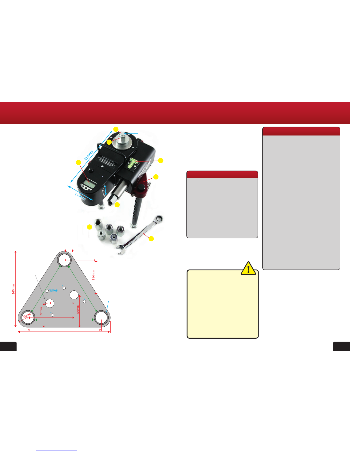
Model 2008 Tester Parts
1. Operating Nut
2. Digital Gauge
3. Load Spreading Bridge
4. M20 Connecting Rod
5. M20 Adjustable Nut
6. 22mm Ratchet Spanner
7. Threaded Adaptors M12-M30
8. Spirit Level
Model 2008 Bridge Footprint
2
SAFETY RULES
• Modication of the tester, or tampering
with it’s parts is not permissible.
• Observe the information printed in the
operating instructions applicable to
operation care and maintenance.
• The tester and its accessories may
present hazards when used incorrectly
by untrained personnel or not as
directed.
• Use only the genuine Hydrajaws
accessories or ancillary equipment
listed in the operating instructions.
The Hydrajaws model 2008
Heavy Duty Tester is designed
for establishing linear loading of
mechanical and resin anchors, eye
type anchors, threaded bar, re-bar
and structural bolts and xings to a
maximum load of 145kN.
USE OF THE TESTER AS DIRECTED
The tester is intended for use by skilled
personnel with the appropriate training
and knowledge of the applicable
safety precautions.
GENERAL DESCRIPTION
It is essential that the
operating instructions
are read before the tester is
operated for the rst time.
Always keep these operating
instructions together with
the tester.
Ensure that the operating
instructions are with the
tester when it is given to
other persons.
TECHNICAL SPECIFICATIONS
Intelligent digital pressure gauge
• 0-145kN (4 segment LCD display)
• Accurate to +/-2.5% FSD
• Indication of pull-out load
• Rise and fall output
• Maximum load achieved function
• Calibration in kN
• Traceable Calibration Certicate
supplied valid for 1 year
• Material: stainless steel and ceramic
• Battery Powered (PP3)
2008 Model Tester
1
7
8
3
6
2
4
5
26mm
* Mounting
Holes
Feet Outer
Edge
x 2 proles for
dierent
edge distance
75m
230mm
290mm
173mm
173mm
188mm
35mm
Dia
40mm Dia
CONTENTS
Page
2008 Model Tester Parts 2
General description 3
Technical Specications 3
Kit contents 4
1. LOAD SPREADING
BRIDGE - set up 5
2. General Testing
Procedure - set up 6
3. General Testing
Procedure - Operating the tester 7
4. Eyebolt Testing 8
5. Re-bar operating instructions 9
6. 2008 MODEL TESTER ASSEMBLY
TO 12.5 TON LOAD SPREADING
BRIDGE 11
6. GENERAL GUIDELINES
FOR TESTING 11
7. Operating the digital gauge 12
8. Operating instructions for
optional Bluetooth Digital Gauge 13
9. Changing the gauge battery 14
10. Calibration/Repair/
Replacement of gauge 14
11. Bluetooth Digital Option Cable removal 15
4 5
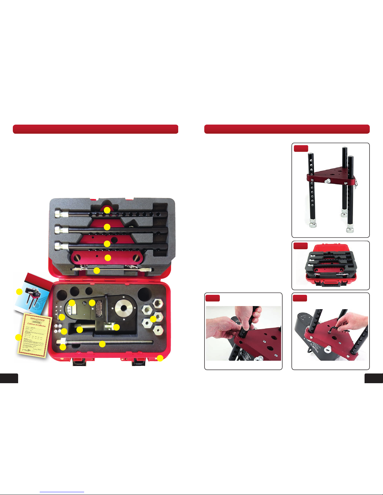
1. Model 2008 Tester Body
2. 22mm Operating Nut
3. 0-145kN Digital Gauge
(Bluetooth version optional for recording
data via suitable mobile device)
4. Offset Load Spreading Bridge plate with
10mm eye hook
5. 3 Telescopic legs with fully adjustable
swivel feet
6. M20 Connecting Rod 400mm
7. M20 Adjustable Nut
8. M24 Ratchet Spanner
9. 5 Threaded Adaptors
M20 > M12, M16, M20, M24, M30
10. Spirit level
11. Allen Keys
12. Spare screws
13. Carry Case with Foam Filler
14. Operating Instructions
15. Calibration Certicate
KIT CONTENTS
1
2
12
11
8
5
5
5
6
7
9
13
3
4
10
1. LOAD SPREADING BRIDGE - set up
Operating Instructions
HYDRAJ AWS
LIMITED
2008 Model Tester
14
Fig 1
Fig 2
Fig 4Fig 3
15
The bridge has been designed specically
for the model 2008 tester and directs
reaction loads away from the xing (g 1).
The lightweight aluminium load spreading
bridge ts in the carry case disassembled
(g 2). The bridge is simple to assemble
and adjust. Three fully adjustable telescopic
legs offer 11 height positions 25mm apart
(g 3). The legs are held in place with
steel ball pins.
The swivel feet offer 30mm of ne
adjustment.
The triangular shape bridge plate is
deliberately offset to offer two different
close to edge testing distances in
relationship to the xing under test.
The tester can be secured to the bridge
plate in two positions with the supplied
cap screws (g 4). Securing the tester
to the plate is not crucial when the tester
is being operated in a horizontal position
however is essential when the tester is in
a vertical position or inverted.
 Loading...