

Page 1
Safety
Lifeline Tester
Operating Instruction
Page 2
1
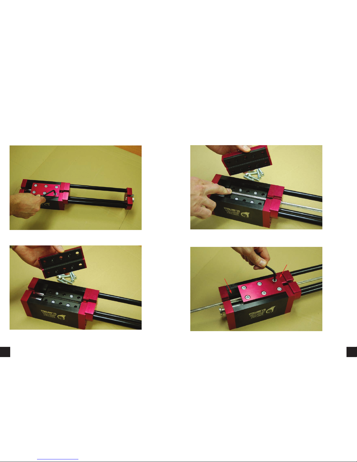
1. With the cable tester clamp side up, remove the 6 cap head
screws and the top plate clamp using the 6mm A llen key.
(Figures 1 and 2).
Figure 1
Figure 2
2. Slide the cable through the slots, replace the top clamp plate
and the 6 cap head screws and tighten up using the 6mm Allen
key. Note the position of the clamp in Figure 4.
Figure 3
Figure 4
2
Gap here
Clamp against
block
Page 3
4
3
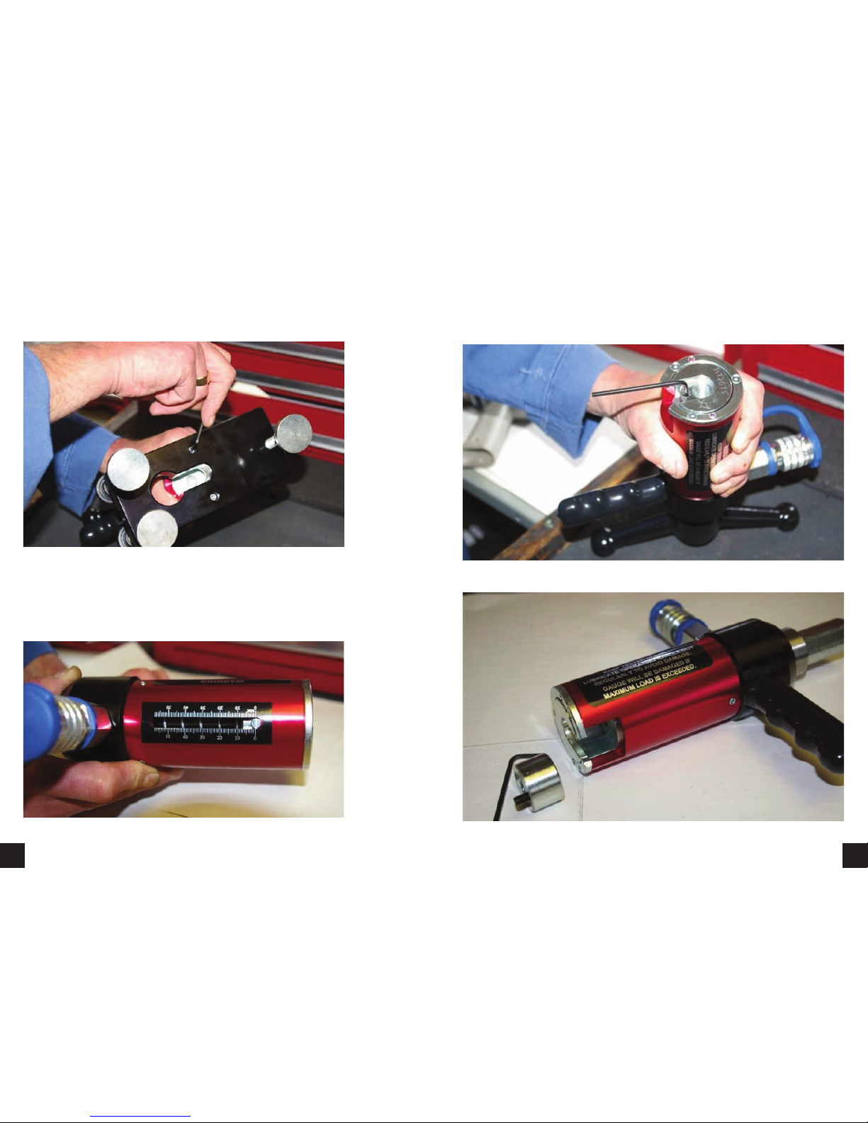
3. Remove the 150 load spreading bridge with adjustable
feet by unscrewing the 2 M4 cap screws on the underside of
the unit. (Figure 5).
Figure 5
5. Remove the M12 round locking adaptor from the inside slot
on the bottom of the portable tensioner by first unlocking /
slackening the allen screw. (Figures 7 and 8).
Figure 7
Figure 8
4. Make sure that the jaw on the tester is fully closed. Check this
by looking at the mm scale on the main body of the tester which
should be near the zero indicator. (Figure 6).
Figure 6
Page 4
6
5
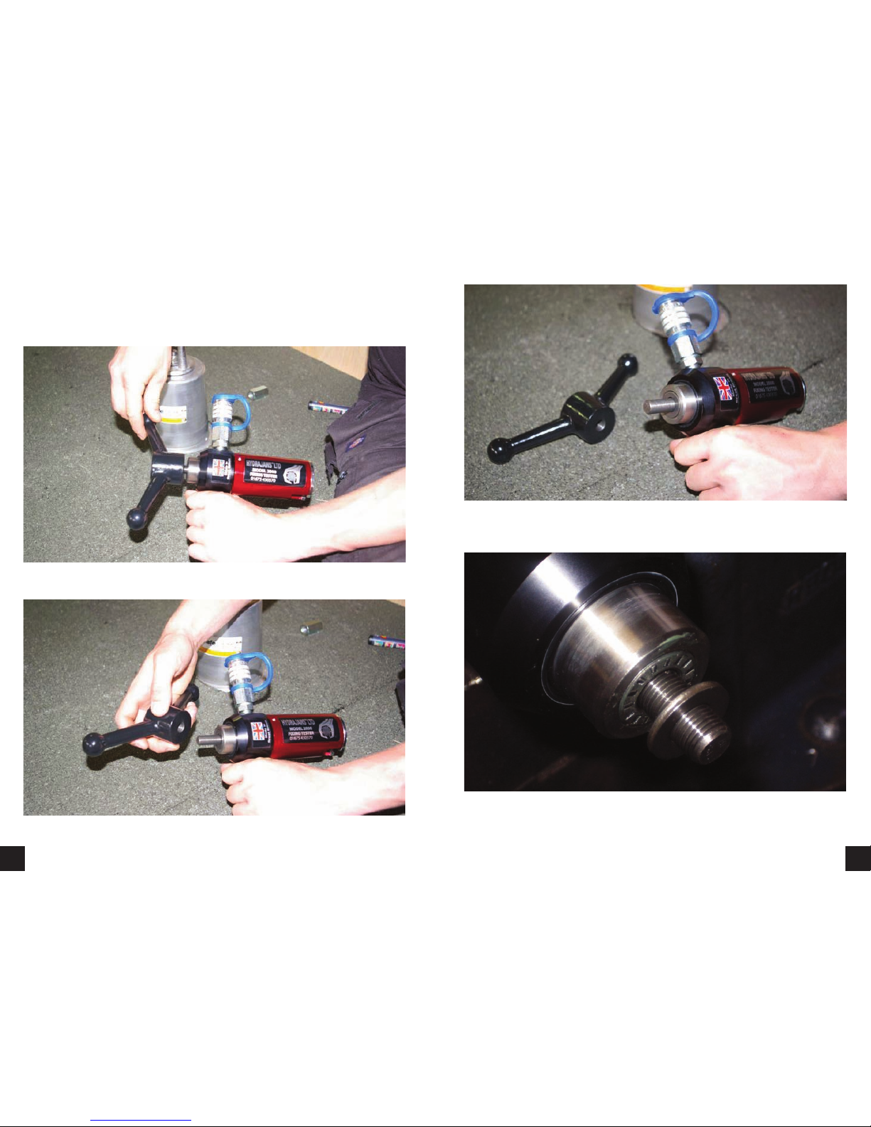
6. Remove the operating ball handle from the tester by
unscrewing anti-clockwise taking care not to remove the bearing
and pressure washers. (Figures 9, 10, 11 and 12).
Figure 10
Figure 9
Figure 11
Figure 12
Page 5
8
7
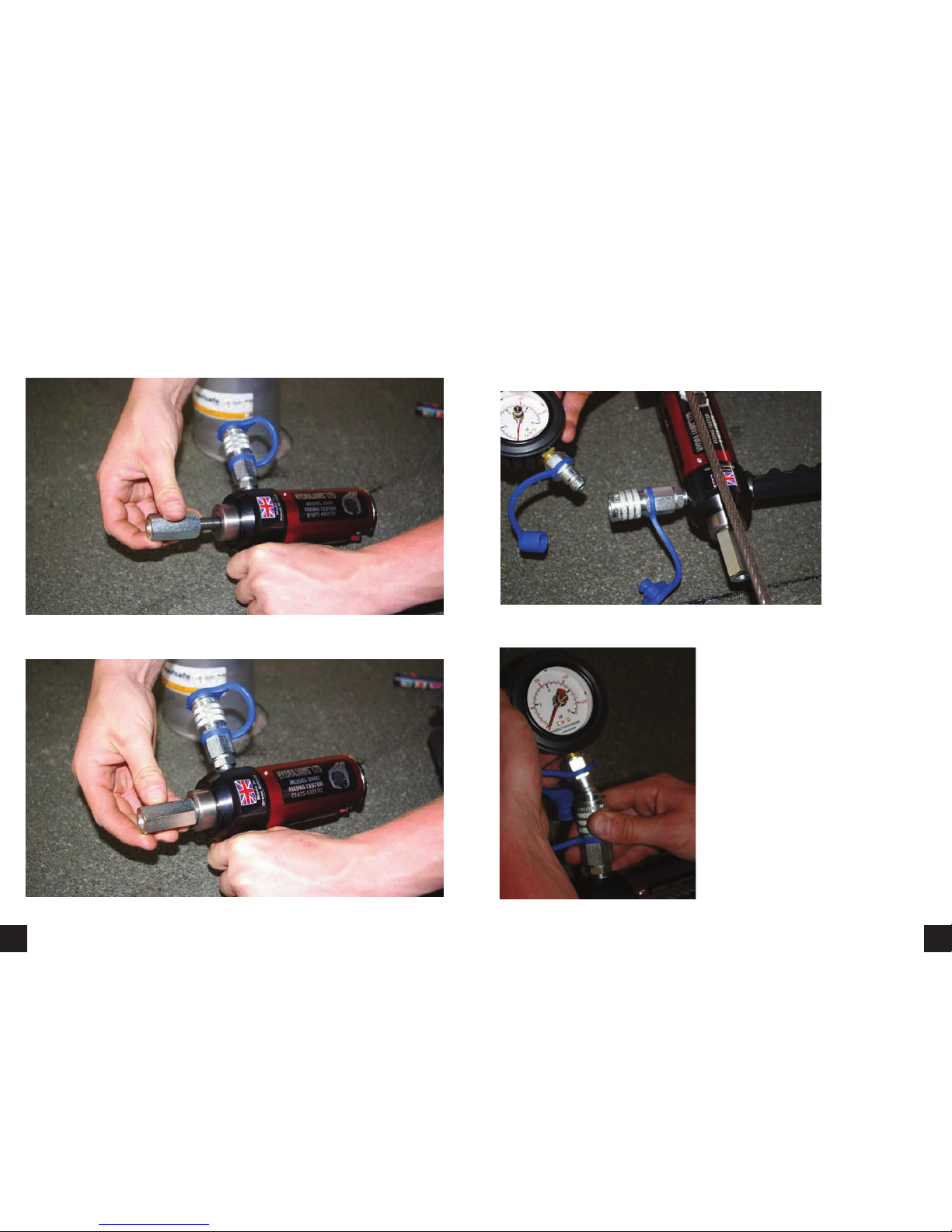
7. Fit the M22/AF hexagon operating nut in place of the handle.
(Figures 13 and 14).
Figure 13
Figure 14
8. Attach the 0-25kN gauge to the Model 2000/C tester by
pulling back on the body coupler and clicking into place. Turning
the gauge will allow for easy reading (gauge only moveable with
coupler system fitted). (Figures 15 and 16).
Figure 15
Figure 16
Page 6
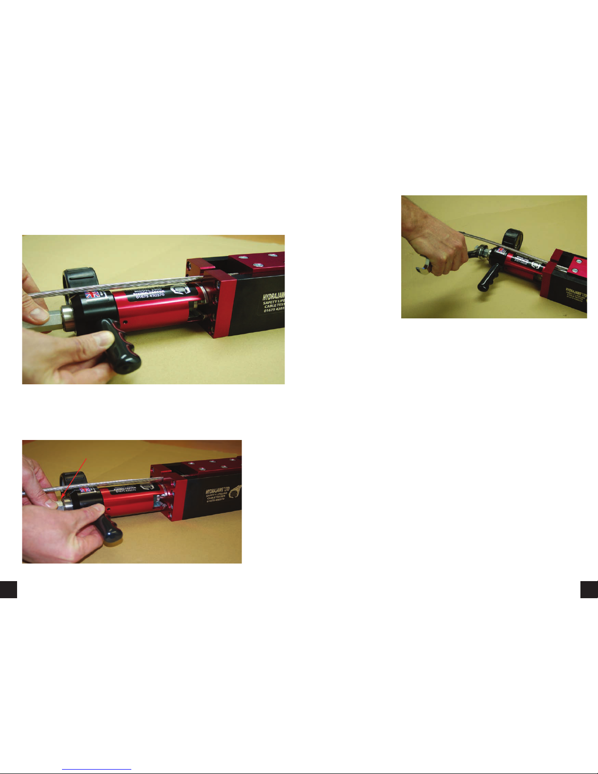
10. Operate with
the M22 ratchet
spanner to
progressively
increase the load
on the swage and
note the readings
on the gauge.
(Figure 19).
Figure 19
9. The Model 2000/C test should be located over the button
adaptor on the opposite end to the swage under test. (Figures 17
and 18).
Figure 17
Figure 18
Turn operating nut by hand to apply enough tension to secure
tester.
Turn clockwise
Page 7
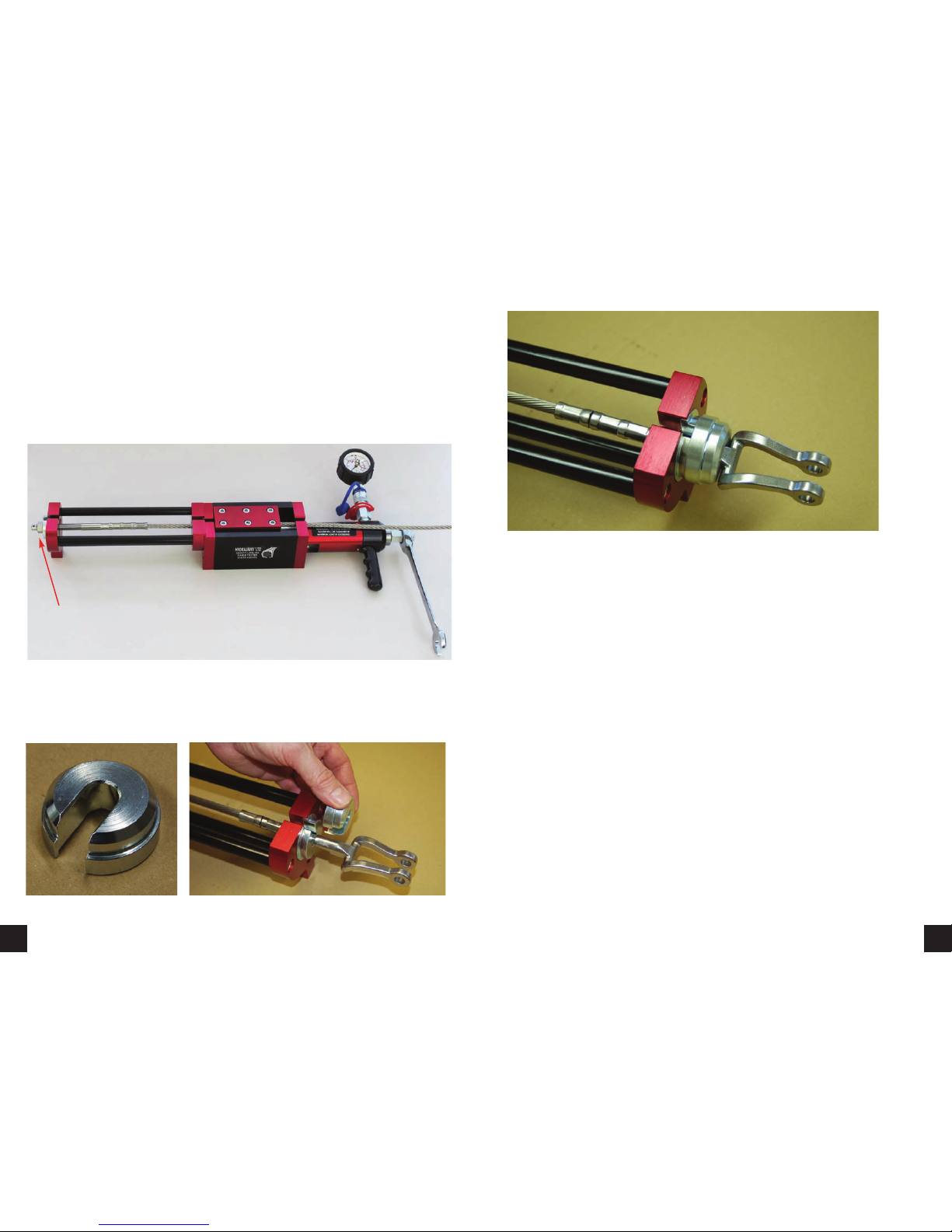
11. The following can be used with the appropriate L/H or R/H
nut. (Figure 21).
85160-00 R/H threaded swage
85162-00 L/H threaded swage
20502-00 Extended L/H swage
Figure 21
12. The following can be used with the supplied collar. (Figures
22, 23, 24).
RH/LH nut
Figure 23
Figure 22
Figure 24
Page 8
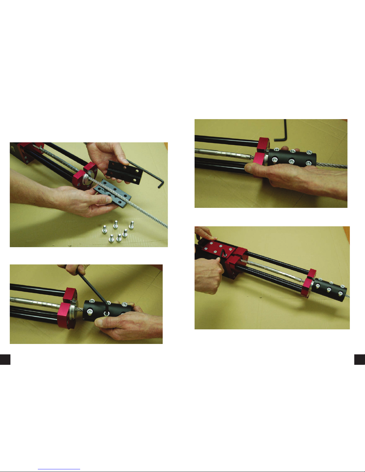
.31 Swage Joiner: use of the extra cable clamp is required.
(Figures 25, 26, 27, 28). Please note the difference of the ends of
the clamp as it is designed to locate slightly over the end block.
Figure 28
Figure 26
Figure 27
Figure 25
Page 9

If any signs of slippage are detected the swage joint must
be rejected and replaced.
For mechanically fixed end and intermediate anchors
secured to structural steelwork the fixing bolts shall be
subjected to a torque check to the recommended values.
If the tightening torque value is not achieved the fixing
bolts shall be replaced.
For systems supplied in kit form by the swaged
connections between the absorber or termination
and cable has been proof tested to 15kN.
Therefore, the system can be directly installed on to the
structure without the need for proof testing on site
provided the maximum predicted end load does not
exceed 15 kN. If the predicted end load is greater than 15
kN then a proof test to the maximum predicted end load
shall be carried out as described below.
For systems supplied as individual parts the swage
connection will need to be completed on site using the
recommended hexagonal dies with a minimum of 3 swage
bites. The connection shall be proof tested to the
maximum predicted end load before installation of the
system. After swaging it is recommended that the across
flats dimension is checked.
The maximum across flats
dimension is 11.2 mm. Any swages greater than 11.2 mm
must be rejected.
It is recommended that the Hydrajaws test kit is used to
perform all the proof tests described below.
For swage testing, apply the recommended test load and
hold for 3 minutes, checking for any slippage of the cable
from the swage. This will be indicated by the gauge not
holding load and separation of the swage slip indicator
(85025) away from the end of the swage termination.
14. Test Load
Page 10
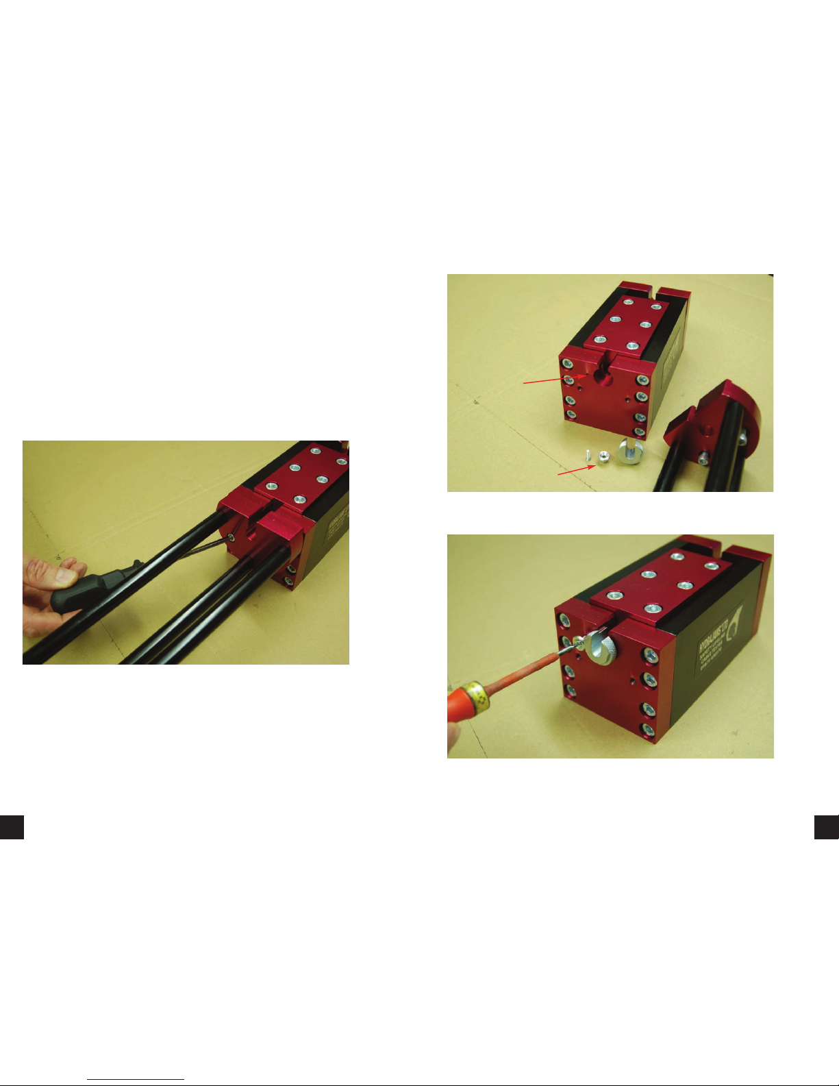
15. Testing procedure of non “slip indicator” cable swages.
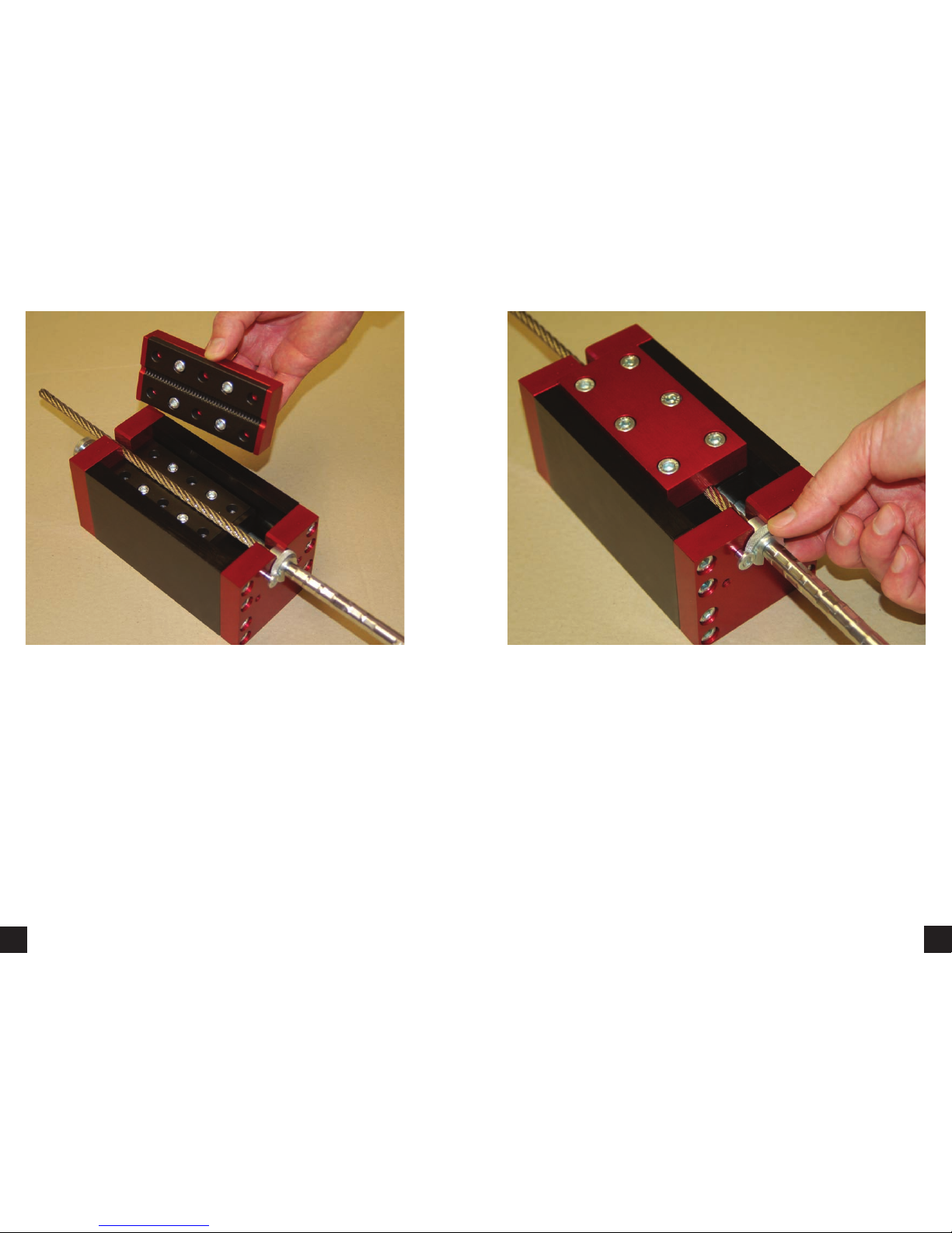
(Figures 29, 30, 31, 32, 33). Remove the extension bars by
unscrewing the 2 6mm cap head screws using the 5mm ball
driver.
Place the kurled adaptor into the end of the block and fix with
the 3mm countersunk screw and collar. Do not overtighten the
.etator ot eerf eb dluohs rotpada delrunk eht sa wercs mm3
Figure 29
Figure 30
Figure 31
Collar
3mm
screw
Page 11
20
19
Figure 32
Figure 33
 Loading...