

Hydra-Flex Pressure Booster Pumps User Manual
Operating Instructions & Parts Manual
5.28
Please read and save these instructions. Read carefully before attempting to assemble, install, operate or maintain the product
described. Protect yourself and others by observing all safety information. Failure to comply with instructions could result in personal injury and/or property damage! Retain instructions for future reference.
Pressure Booster Pumps
FW0154
0813
Supersedes
0113
Description
Pressure booster pumps increase water pressure from city mains or private water systems. Applications include providing high water pressure for washing buildings, dairy
walls or floors, hog parlors, poultry houses, rinsing or spray cooling equipment, lawn
sprinkling and insecticide spraying.
Single-phase models are equipped with a capacitor start, thermal protected motor.
Three-phase models require separate overload protection.
2 & 3HP
4.88
TEFC ONLY
3.88
1Ø TEFC ONLY
3.75
6.50
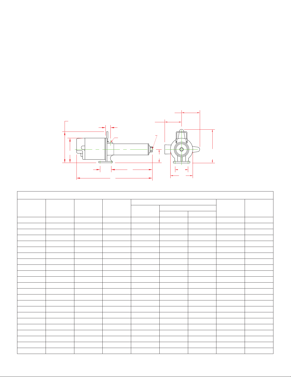
Figure 1
(MODELS WITH HANDLES)
7.15
9.00
1.44
"H" INLET
3.25 "C"
"F"
"J" DISCHARGE
Unpacking
When unpacking the unit, inspect carefully for any damage that may have
occurred during transit.
NOTE: Use pump with clear water
only.
9.75
1-1/2 & 2HP 1Ø TEFC
ALL 3HP 1Ø
IL0391B
Pump Dimensions 60 Hz Chart A
F
HP GPM Stage “C”
1/3 5 8 10.19 19.81 - - .75 .75
1/3* 5 8 10.19 20.06 22.04 - .75 .75
1/2 5 12 13.38 23.25 23.23 24.10 .75 .75
1/2* 5 14 14.97 25.34 26.82 25.69 .75 .75
3/4 5 16 16.54 26.91 28.77 27.51 .75 .75
3/4 7 12 13.38 23.75 25.61 24.35 .75 .75
3/4* 7 14 14.97 25.84 27.20 25.94 .75 .75
1 10 14 16.31 27.18 29.16 28.02 .75 .75
1-1/2 10 16 18.13 29.62 31.48 30.07 .75 .75
1* 10 20 21.69 33.18 34.54 33.40 .75 .75
1* 10 22 23.50 34.99 36.35 35.21 .75 .75
1* 10 23 24.38 35.87 37.73 36.09 .75 .75
2 19 14 17.89 29.88 32.12 30.87 .75 .75
1-1/2* 19 20 24.06 36.05 37.41 36.00 .75 .75
2* 19 22 26.13 38.12 40.36 39.11 .75 .75
2 27 11 15.38 27.37 29.61 28.36 1.00 1.00
3 27 14 18.50 30.49 33.85 33.35 1.00 1.00
2* 27 17 21.59 33.58 35.82 34.57 1.00 1.00
3 27 17 21.59 33.74 - - 1.00 1.00
2 35 6 13.94 25.93 28.17 26.92 1.00 1.00
3 35 8 17.13 29.12 32.48 31.98 1.00 1.00
1-1/2* 35 8 17.13 29.12 30.48 29.07 1.00 1.00
3* 35 14 26.86 38.85 42.21 41.71 1.00 1.00
F&W
1 Phase 3 Phase
TEFC
H J
Copyright © 2012 FLINT & WALLING, INC. • 95 North Oak St. • Kendallville, IN 46755 • flintandwalling.com
1
132934
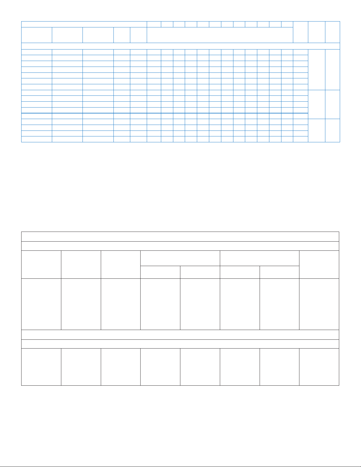
PRESSURE ADDED - PSI 10 20 40 60 80 100 120 140 160 180 200 220
Stainless Steel
Fitted
PB0508S031 PB0508C031 PB0508A031‡ 1/3 8 10.2 9.6 8.3 6.5 4.3 96
PB0512S051 PB0512C051 PB0512A051‡ 1/2 12 10.0 9.5 8.3 7.1 6.0 4.0 2.3 132
PB0516S071 PB0516C071 PB0516A071 3/4 16 10.2 9.7 9.1 8.3 7.5 6.6 5.8 4.6 3.3 189
PB0712S071 PB0712C071 PB0712A071 3/4 12 14.0 13.4 12.2 10.9 9.5 8.9 7.0 4.6 158
PB1014S101 PB1014C101 PB1014A101 1 14 * * 14.5 13.4 12.3 11.2 9.8 8.0 6.0 2.3 183
PB1016S151 PB1016C151 PB1016A151 1-1/2 16 * * 15.0 14.1 13.1 12.1 11.0 9.8 8.2 5.2 2.0 212
PB1914S201 PB1914C201 PB1914A201 2 14 27.6 27.0 25.7 24.2 22.6 20.8 18.7 16.2 12.9 7.7 190
PB3506S201 PB3506C201 PB3506A201 2 6 48.0 47.0 42.5 35.2 24.0 85
PB2711S201 PB2711C201 PB2711A201 2 11 * * 31.5 29.5 27.1 24.2 20.3 13.0 147
PB3508S301 PB3508C301 PB3508A301 3 8 48.0 47.5 44.0 40.0 35.2 27.5 118
PB2714S301 PB2714C301 PB2714A301 3 14 * * 33.0 31.5 29.8 27.9 25.6 22.8 18.9 11.1 187
PB2717S303** - - 3 17 * * * 34.1 32.3 30.5 28.3 25.8 23.1 20.0 16.6 11.4 225
- - PB5504A201 2 4 77.6 71.5 52.5 55
- - PB5506A301 3 6 77.8 74.4 65.0 51.1 31.9 83
- - PB8504A201 2 4 105.8 90.0 47.0 49
- - PB8505A301 3 5 108.8 98.8 60.0 25.0 60
‡ Equipped with carrying handle. 132079 handle available as an option for other models.
† Example: If PB0508A031 pump is connected to supply line of sufficient capacity, carrying water at 40 PSI, and the output of the pump is held to 7.3 GPM by a gate
valve, the pump will add 40 PSI to line pressure for a total output pressure of 80 PSI.
* Operation of pump in this range may result in reduced pump life and/or motor damage.
To keep pump and seal lubricated, a minimum flow of 1.5 GPM must always be maintained through the pump.
** Only available in 3 phase
Motor voltage: Open Drip Proof Totally Enclosed Fan Cooled
Powder-
Coated Cast
Iron Fitted
Single Phase 1/3 - 2 HP - 115/230; 3 HP - 230V 60 Hz.
Three Phase 1/2 - 2 HP - 208-230/460, 50/60Hz.
Three Phase 3 HP - 208-230/460, 60 HZ
For three phase models, use suffix “3” on the model no.
Example: PB0512A053
Cast Iron Fitted HP Stage Output - Gallons per Minute
60Hz Models
Single Phase: 1/2 thru 3 HP - 115/230V 60/50Hz
Three Phase: 1/2 thru 3 HP - 208/230/460V 60/50Hz
Max.
Press.
PSI
Suction
Pipe
Tap
NPT
3/4” 3/4”
1” 1”
2” 2”
Disch.
Pipe
Tap
NPT
Single Phase Motor Data 60HZ Chart C
Single Phase† 60 Hz 3450 RPM Capacitor Start
HP
1/3
1/2
3/4
1
1-1/2
2
3
Motor
Voltage
115/230
115/230
115/230
115/230
115/230
115/230
230
Factory
Connected
Motor
Voltage
115V
115V
115V
230V
230V
230V
230V
Service Factor Motor
Amps
Locked Rotor Motor
Amps
115V 230V 115V 230V
8.6
13.0
14.0
18.0
21.0
25.0
-
4.3
6.5
7.0
9.0
10.5
12.5
13.5
26.0
36.0
52.0
78.0
98.0
116.0
-
13.0
18.0
26.0
39.0
49.0
58.0
53.0
Code Letter
K
K
K
L
J
H
D
Single Phase Motor Data 50HZ
Single Phase† 50 Hz 2850 RPM Capacitor Start
1/2
3/4
1
1-1/2
2
†Thermal overload protector - automatic reset
115/230
115/230
115/230
115/230
230
115V
115V
230V
230V
230V
10.0
14.4
16.4
23.6
-
5.0
7.2
8.2
11.8
13.2
48.0
64.0
72.0
104.0
-
24.0
32.0
36.0
52.0
55.0
M
L
K
K
H
Copyright © 2012 FLINT & WALLING, INC. • 95 North Oak St. • Kendallville, IN 46755 • flintandwalling.com
2
Three Phase Motor Data Chart D
Three Phase† 60/50 Hz 3450/2850 RPM Capacitor Start
HP
3/4
1
1-1/2
2
3
Motor
Voltage
208-230/460
208-230/460
208-230/460
208-230/460
208-230/460
Factory
Connected
Motor
Voltage
230V
230V
230V
230V
230V
Service Factor Motor
Amps
Locked Rotor Motor
Amps
230V 460V 230V 460V
3.5
4.5
5.7
7.4
9.8
1.75
2.25
2.85
3.70
4.90
19.0
26.9
33.5
44.0
48.0
13.5
16.8
22.0
24.0
9.5
Code Letter
K
K
K
K
D
3 HP, 3 Phase motor operable on 60Hz only.
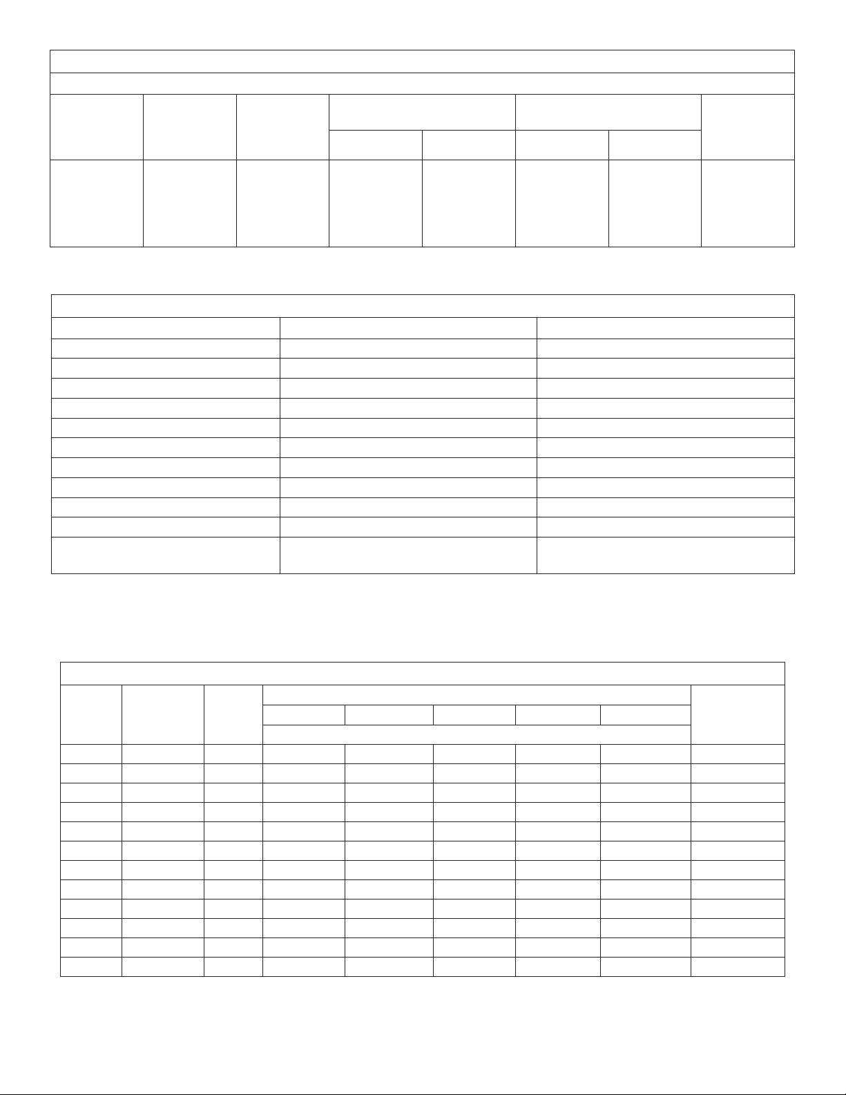
Material Construction Chart E
Component Standard Models* Stainless Steel Models
Motor Rear access - Nema 56J face Rear access - Nema 56J face
Bearings Ball-ball, permanently lubricated Ball-ball, permanently lubricated
Impellers Noryl with 304 stainless steel bearing insert Noryl with 304 stainless steel bearing insert
Diffuser Noryl Noryl
Diffuser plates Delrin Delrin
Pump shaft 416 Stainless steel 304 Stainless steel
Pump shaft coupling 316 Stainless steel 316 Stainless steel
Pump shell 304 Stainless steel 304 Stainless steel
Discharge & inlet casting Cast iron 304 Stainless steel
O-Rings Buna-N Viton
Seal composition Carbon-silicon carbide, stainless steel spring
and Buna-N
*Models with powder coated inlet & discharge also available.
Carbon-silicon carbide, stainless steel spring
and Viton
Minimum Wire Size Chart (Gauge) Chart F
Motor
HP
1/3 115/230 1 14/14 14/14 14/14 12/14 12/14 15/15
1/2 115/230 1 12/14 12/14 12/14 12/14 10/14 15/15
3/4 115/230 1 12/14 12/14 10/14 10/12 8/12 15/15
1 115/230 1 10/14 10/14 10/12 8/12 6/10 20/15
11/2 115/230 1 10/12 8/12 6/12 */10 */10 30/15
2 115/230 1 10/12 8/12 6/12 */10 */10 30/15
3 230 1 10 10 10 10 8 20
3/4 230/460 3 14/14 14/14 14/14 14/14 14/14 15/15
1 230/460 3 14/14 14/14 14/14 14/14 12/14 15/15
11/2 230/460 3 14/14 14/14 14/14 12/14 12/14 15/15
2 230/460 3 14/14 14/14 14/14 12/14 10/12 15/15
3 230/460 3 14/14 14/14 14/14 12/14 10/12 15/15
(*) Not economical to run in 115V, use 230V.
Volts Phase
Copyright © 2012 FLINT & WALLING, INC. • 95 North Oak St. • Kendallville, IN 46755 • flintandwalling.com
0-50 50-100 100-150 150-200 200-300
Distance In Feet From Motor To Service Panel
Breaker Size
(Amps)
Wire Size
3
General Safety Information
!
!
!
!
!
!
Carefully read and follow all safety instructions in
this manual and on pump. Keep safety labels in good
condition. Replace missing or damaged safety labels.
9. Do not insert finger or any object into pump or motor
openings.
10. Secure the discharge line before starting the pump. An
unsecured discharge line will whip, possibly causing personal injury and/or property damage or puncture.
symbol on the pump or in the manual, look for one of the
following signal words and be alert to the potential for personal injury or property damage.
personal injury, death or major property damage if ignored.
personal injury or death, if ignored.
personal injury, product or property damage if ignored.
This is a SAFETY ALERT SYMBOL. When you see this
Warns of hazards that WILL cause serious
Warns of hazards that CAN cause serious
Warns of hazards that MAY cause minor
IMPORTANT: Indicates factors concerned with operation,
installation, assembly or maintenance which could result in
damage to the machine or equipment if ignored.
NOTE: Indicates special instructions which are important but
are not related to hazards.
Wire motor for correct voltage. See
“Electrical” section and Motor Data Charts
C&D of this manual, and motor nameplate.
Ground motor before connecting to
power supply.
Hazardous voltage. Can shock,
burn or cause
death. Ground
pump before connecting to power
supply.
Meet United States National Electrical
Code and local codes for all wiring.
Do not handle a pump or pump motor
with wet hands or when standing on a wet
or damp surface or in water.
engine. They are designed to operate at high temperatures.
the State of California to cause cancer and birth defects or
other reproductive harm.
been investigated for use in swimming pool areas.
NOTE: Pumps with the “CSA-CUS” mark are tested to UL standard UL778 and certified to CSA standard C22.2 No. 108.
Pre-Installation
HANDLING
1. Use handle supplied to lift pump.
2. Avoid impact on pump or motor. In particular, avoid
impact on discharge end of pump or rear motor access
cover.
LOCATION
age and/or personal injury might result from an inoperative
or leaking pump due to power outages, discharge line blockage, or any other reason, a backup system(s) should be used.
1. Locate pump as close to the fluid source as possible, keeping the inlet pipe short as possible.
2. Place unit where the pump and piping are protected from
the weather and extremes of heat, humidity and below
freezing temperatures.
3. Mount unit in a dry location that is easily accessible for
inspection and maintenance. If a dry location is not available, mount it on a foundation well above the wet floor.
Do not touch an operating motor or
This product contains chemicals known to
Risk of Electric Shock. This pump has not
In any installation where property dam-
4. Allow ample clearance around unit for free air circulation.
Follow wiring instructions in this manual when connect-
ing to power lines.
SUCTION LIMITATIONS
1. Units are non self-priming.
2. Pressure booster pumps are not recommended for suction
performing any work on or near the motor or its connected
Always disconnect power source before
load.
lift applications.
PIPING
1. Use galvanized piping, rigid plastic or other suitable pipe
that will not collapse under suction or rupture due to pressure.
such as gasoline, fuel oil, kerosene, etc. Do not use in flam-
Do not use to pump flammable or explosive fluids
mable and/or explosive atmospheres.
forced industrial type that is rated higher than the shutoff
pressure of the system. Ordinary garden hose will collapse
and starve the pump of water.
If hose is used, make sure it is the rein-
2. The diameter of the inlet and discharge pipe should be
discharge pipe. Release all pressure on system before work-
Hazardous pressure! Install pressure relief valve in
ing on any component.
1. Make workshop child proof - use padlocks, master
switches; remove starter keys.
2. Wear safety glasses when working with pumps.
3. Wear a face shield and proper apparel when pumping
hazardous chemicals.
4. Keep work area clean, uncluttered and properly lighted;
replace all unused tools and equipment.
no smaller than the corresponding ports of the pump (See
Figure 1). Smaller pipe will reduce the capacity of the
pump. Increase pipe size on long runs.
3. Avoid air pockets in inlet piping or air will accumulate at
high points, making priming difficult.
4. Use pipe compound on all joints and connections. Use
Teflon tape or plastic joint stik, on plastic pipe. Draw all
pipe up tightly.
IMPORTANT: The entire system must be air and water tight
for efficient/proper operation.
5. Provide guarding around moving parts.
6. Keep visitors at a safe distance from the work area.
7. Periodically inspect pump and system components.
8. Protect electrical cord. Replace or repair damaged or
worn cords immediately.
Copyright © 2012 FLINT & WALLING, INC. • 95 North Oak St. • Kendallville, IN 46755 • flintandwalling.com
4
IL0418
IL0420
IL0421
Installation
!
PUMP INSTALLATION
IMPORTANT: Pump is built to handle
clear water only; it is not designed to
handle water containing sand, silt or
other abrasives.
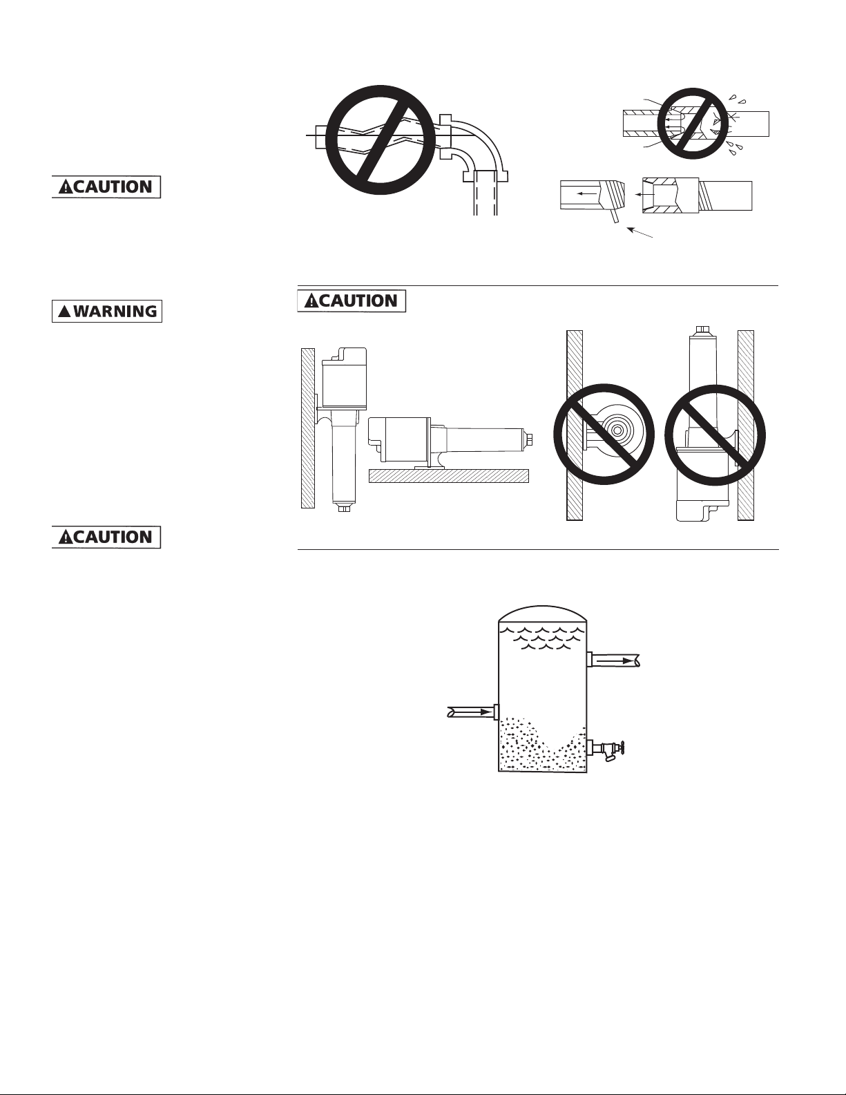
1.Refer to Figures 6, 7, and 8 for typical installations.
No Sags
Sags Allow Air Pockets
No Air Leaks In
Inlet Pipe
If Air Flows
Water
Won’t
Pipe Joint Compound
Will Damage Plastic
IL0419
piping when assembling and when
Support pump and
installed. Failure to do so may cause
piping to break, pump to fail, motor
bearing failures, etc.
2. If the pump is used as part of a permanent installation, bolt to a rigid
foundation.
Use only components that are rated for maximum pressure pump can produce when used in
boosting system or any other system.
Do not exceed the total maximum
pressure boost as listed per model in
Performance Charts B.
PRESSURE BOOST SYSTEMS
1. On pressure boost systems, locate
the pump so that there will always
be a positive supply of water to the
pump (See Figures 6, 7 and 8).
2. For service convenience, install a
gate valve and union in the inlet
and discharge line.
Do not use a globe
valve or other restricting type of valve
that will seriously restrict the pumps
discharge capacity.
3. Install a check valve as shown in
Figure 6. Be sure check valve flow
arrows point in the direction of
water flow.
4. Whenever dirt, sand or debris is
present in the supply water, install a
strainer or filter on the inlet side of
the pump (See Figure 7).
NOTE: For heavy amounts of sediment, install a trap filter on the inlet
side of the pump (See Figure 5).
NOTE: Pressure gauges installed
before and after the filter will show
pressure differential indicating the
need for filter replacement or cleaning.
If Air Pockets Form,
Water Won’t Flow
Figure 2 - No Air Pockets in Inlet Pipe
Mount pump in correct position or pump failure will result.
Correct
Figure 4A Figure 4B
IL1013
Figure 3 - Inlet Pipe Must Not Leak
Use Teflon Tape
Incorrect
SAND AND SEDIMENT TRAP FILTER
Standard Pressure
Tank - 42 Gallon Or
Larger
Outlet
Inlet
Sand Settles To The Bottom
Figure 5
Clean Out
IMPORTANT: Clean all filters and strainers on a regular schedule.
IL1014
Copyright © 2012 FLINT & WALLING, INC. • 95 North Oak St. • Kendallville, IN 46755 • flintandwalling.com
5
 Loading...