

- 1 -
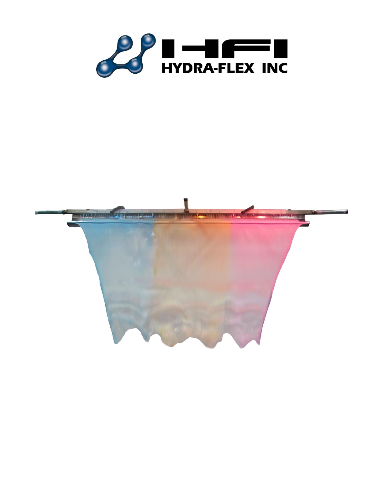
Tsunami™ Dispensing Arch
Using
™
AQUA-LAB
Chemical Dispensing System
REV A
© Hydra-Flex Inc 2011
- 2 -
Chemical Dispensing Specifications
1. Operating water pressure: 200 psi (Factory set)
2. Maximum water source temperature 140° F
3. Operating ambient temperature: 40-120° F
4. Electrical supply
a. 120 / 208 Single Phase
b. 1.5 hp pump 20 amps @ 120 volts or 10 amps @ 208
volts
5. Operate valves with 24VAC, 24VDC, 120VAC
a. < .5 amp
6. Water supply
a. 3/4” ID flooded inlet required
b. Inlet pressure: 2-60 psi
7. Air supply
a. Pneumatics inlet pressure: 60 - 100 psi
b. 3/8” feed per system
c. 20 CFM @ 100 psi supply
d. 3 x 3/8” poly lines to applicator
8. Chemical Solution lines
a. 3x ½” poly lines to applicator
9. Space requirements:
a. AQUA-LAB Systems
i. Valve panel – 1.5’ wide x 2’ tall
ii. Pump – 1’ wide x 4’ tall
b. Pump assemblies – pumps need to be within 6’ of the
system to allow connection with the connection hose
included (longer connections can be run with customer
supplied hose)
c. Electrical enclosures
i. Motor starter – 12” wide x 6” tall
Tsunami Applicator Specifications
1. Operating water pressure: 100 psi max
2. Pneumatics inlet pressure: 0-60 psi
3. Maximum water source temperature 140° F
4. Operating ambient temperature: 40-120° F
5. Water supply
a. 4 – 10 GPM
b. Inlet pressure: 10-65 psi
6. Air supply
a. 3x 3/8” feed per system
b. ~20 CFM
7. Solution lines
a. 3x ½” poly lines to applicator
8. Mounting requirements
a. This Applicator requires an arch to mount to
b. Must be level
c. Recommend roughly centering on car or slightly favoring the driver’s side
© Hydra-Flex Inc 2011
- 3 -
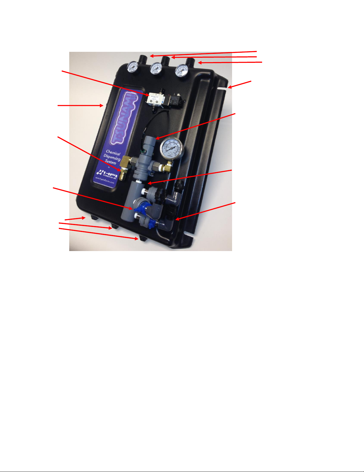
System Component Identification
Air Regulator 1, 2, 3
Air Solenoid
Valve Board Mounting Slots
Air Inlet
(3/8” Poly) Pneumatically
Actuated Valve
Water Feed
From Pump
(200psi)
Triple Foam
Manifold
Chemical
Injector
3x Outlet to Applicator
Air Outlet 1,
2, 3
© Hydra-Flex Inc 2011
- 4 -
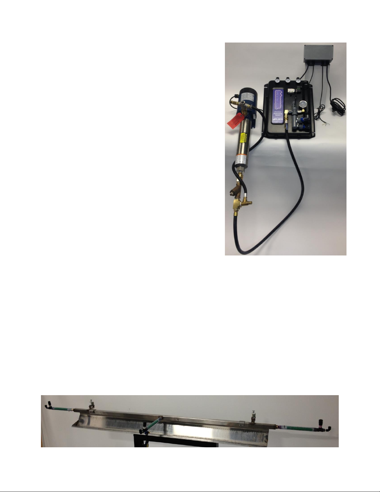
1. Mount pump using 4x 3/8” wedge Anchors provided (3/8” hammer drill required)
a. Mounting slots 3.75”W x 3.38”H
2. Mount electrical box and delivery panel using Tapcon anchors provided (5/32” hammer drill
required)
a. Electrical Box – Hole spacing 7.4”W x 3.5”H
b. Panel – Slot spacing 17.5”W x 15”H
3. Run ¾” water line to the inlet of the pump
4. Close the ball valve on the pump outlet line and open the feed to the pump
5. Point the outlet line towards a drain or a container and open the ball valve until water is flowing
freely to prime the pump.
6. Close the ball valve and attach the quick connect to the chemical delivery panel and re-open
the ball valve
7. Run a 3/8” poly airline to the chemical panel and supply with at least 60psi of air pressure
8. Wire the signal wire from the provided electrical box to the box with the signal to fire the
application
9. Connect the DIN I solenoid cable from the electrical box to the air valve.
10. Check that relay installed in the electrical box corresponds with the signal voltage from the car
wash controller (120VAC relay is installed from the factory, 24 VAC and 24VDC relays are
included inside the electrical box)
11. Plug 120VAC power cord into a circuit with 20 amp available capacity
12. Install or identify an existing arch to mount the Tsunami applicator to
IMPORTANT!! The Tsunami applicator requires a level sturdy arch or other
mounting feature as it does not include one
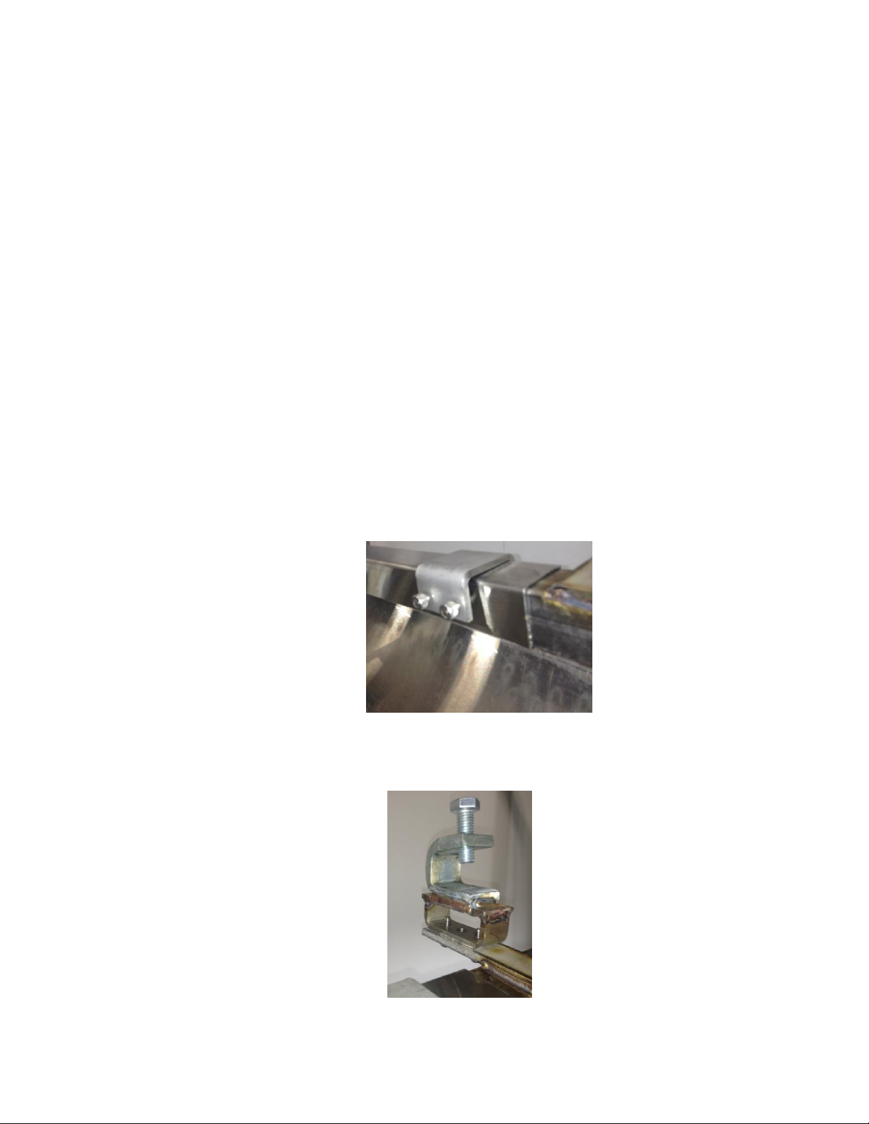
13. Clamp the rain bar into the trough using the provided clamps as shown
14. Center the applicator on the largest vehicle that can safely pass thru the tunnel
15. Make sure that the applicator is level side to side
16. Securely attach the applicator to the arch using the mounting tabs and / or the included
brackets.
17. Run and connect three ½” polyflow lines for the chemical solution and three 3/8” polyflow lines
for the foaming air from the chemical delivery panel to the foam generators on the applicator.
© Hydra-Flex Inc 2011

- 5 -
18. Run chemical lines with foot valves from the chemical barrels to the hose barbs on the
injectors and install metering tips according to desired chemical dilution ( see chemical dilution
ratio chart)
19. Using the car wash controller manually fire the signal for the application.
20. The pump, air valve and pneumatically actuated valve should all turn on.
21. Adjust the chemical ratio and air pressure until you get the desired results.
© Hydra-Flex Inc 2011

- 6 -
Optimizing the System
Consistently achieve the desired cleaning and presentation/performance
using the least amount of chemical and water
Injectors vs. Metering Tips
The key to optimizing the system is through trial and error.
Don’t be afraid to try these steps to achieve your ideal performance.
What do injectors do?
o Increases or decreases the amount of water
in the solution
What do metering tips do?
o Increases or decreases the amount of
chemical in the solution
Application Optimization (repeat for each
application)
View Performance at Arch with Decision Maker
Application too wet
o Increase air
o Reduce injector size (decreases water)
o Increase metering tip (increases chemical)
Application too dry
o Decrease air
o Increase injector size (increases water)
o Decrease metering tip (decreases chemical)
Too much chemical used
o Decrease metering tip
o Decrease metering tip and injector size (to maintain desired ratio)
No chemical
o Check vacuum of injector (see instructions on page 9)
o Check foot valve
o Check metering tip
© Hydra-Flex Inc 2011

- 7 -
Chemical Usage Measuring
Verify titration of chemicals before proceeding
1. Setup lab scale with small bucket of chemical to be measured.
2. Put the suction line into the bucket.
3. Run the application being tested to “prime” the line. (All air bubbles must be removed for accuracy)
4. Record the Initial Weight from the scale. (Tarring the scale with weight on the scale can affect accuracy)
5. Run the application for 6 vehicles (or manually for the same it would be on for 6 vehicles).
6. Record the Final Weight from the scale.
7. Subtract the Initial Weight from the Final Weight to determine the weight of used product.
8. Divide this Used Weight by 6 to get a per car weight.
9. Divide the Per Car Weight in grams by the specific gravity of the chemical to determine the milliliters of chemical
used per vehicle.
10. Repeat for each chemical application.
Recommended Maintenance
The recommended service and maintenance on the AQUA-LAB System are as follows.
Monthly
Check water filter and replace as needed (if installed)
Semi-Annually
Check and replace injector metering tips
Check and clean Y strainer
Inspect and replace chemical lines as needed
Annually
Clean water regulator
Inspect motor starter for corrosion, if identified order replacement/spare parts
2 Years
Inspect and replace injectors
Rebuild valves
Rebuild water regulator
© Hydra-Flex Inc 2011

- 8 -
Troubleshooting
Injector Vacuum Check (for troubleshooting injectors)
1. At the ChemFlex injector, remove the chemical feed line from the injector hose barb.
2. Attach the tubing of the vacuum gauge to the ChemFlex hose barb
3. With the pump(s) on, manually activate the chemical that is to be tested at the main car wash control cabinet. An
injector that is working properly will have a reading greater than or equal to (≥) 20 in Hg
4. If injector is not functioning:
a) Check metering tip for clogs (can be tested with no metering tip to ensure injector is performing)
b) Try smaller injector (this will produce less flow and thus less backpressure)
5. Repeat steps 2-4 for each chemical lane that a vacuum reading is needed for.
6. Once testing is complete, turn off the AQUA-LAB pump from the main car wash control cabinet.
There is a variation of performance in the injectors that comes from slight variations in the dimensions of the parts and in assembly that are
unavoidable. It is common to see the resultant vacuum range from 20 in Hg all the way up to 28. There is also variation in the through hole size on the
meter tips from Dema (within their manufacturing tolerances). Using the same tip color from site to site is a good starting point. However with the
potential for variation from part to part it is reasonable to still need to do some adjustments from there.
© Hydra-Flex Inc 2011

- 9 -
Inlet Restriction
Check all in-line filters and inlet plumbing for restrictions. Check
valves and backflow preventers
Inadequate water supply
Check pressure on inlet side of pump to be sure positive
pressure is maintained
Undersized piping Replace with larger piping
Leak on the Inlet side Make sure connections are tight
Worn or defective pump parts Replace worn parts or entire pump, Clean parts if required
Blown fuse or circuit breaker Replaced fuses or close circuit breaker
Defective Motor Starter
contactor
Replaced motor starter contactor
Incorrect Motor Voltage Voltage must be within 10% of motor rated voltage
Defective motor Replace motor
Pump components damaged Replace worn part or entire pump
Not Primed Reprime pump
Pump not secured firmly Secure properly
Restricted Inlet Clean or correct restriction
Water regulator fluttering
Try to adjust regulator down and then back up or replace
regulator
Cavitation (Sounds like marbles
in pump)
Increase inlet size
Worn mechanical seal Replace shaft seal
Worn o-ring seals Replace
Injector is not
drawing chemical -
Passes Vacuum
Pressure check
Clogged chemical feed
Check chemical hose, foot valve, metering tip and hose barb
for debris or clogs
Too much back pressure on
injector
Perform back pressure check test outlined in Section IV if this
manual. If the result is higher than 66 psi then, use larger
tubing, or use a smaller flow injector
Clogged injector check valve
Blow compressed air through the chemical hose barb on the
injector to remove debris
Clogged injector nozzle Remove injector and blow out any debris with compressed air
Defective Injector
If Vacuum check fails but Back Pressure is less than 66 psi,
replace the injector
Pump won't start or
run at full speed
Pump Operates, but
delivers little or no
water
Injector is not
drawing chemical -
Fails Vacuum
Pressure check
test
Pump Leaks
Excessive Noise from
Pump
© Hydra-Flex Inc 2011

- 10 -
PROBLEM POTENTIAL CAUSES SOLUTIONS
Pump not primed Follow priming instructions
Debris in regulator Remove regulator and clean out debris
Defective Check Valve Replace check valve if broken
Defective Regulator Replace Regulator
Defective Pump Replace Pump
Incorrect Injector Flow Rate
Selection
Replace with desired injector size
System pressure too low Ensure system pressure is set at 200 psi
Foam Generator Plugged Ensure cleaned and clear
Downstream pluming restrictive
Perform Back pressure test outlined in Section IV of this
manual, if over 66 psi, increase tube size and reduce elbows,
turns or other restrictive plumbing
Valve malfunction Ensure valve is receiving at least 60 psi
Valve may be assembled incorrectly
Disassemble valve and clean out debris (See valve
replacement instructions)
Clogged Injector Remove injector and blow out debris with compressed air
No water supply Check that the system has a supply of water
Valve stuck open –
Staying open when
signal is off
Debris in valve seat Remove and clean valve (See valve replacement instructions)
Starter Tripping
Incorrect Overload Setting
Verify overload setting versus settings found in specs page of
this document
Flow at arch is too
low
System won't
regulate up to 200
psi
No flow from injector
© Hydra-Flex Inc 2011

- 11 -
Appendix
© Hydra-Flex Inc 2011

- 12 -
Chem-Flex Injector Listing
Aqua-Lab Chem Flex Injector Listing
Part Number
#
Barbs
GPM
618029
1
0.25
618040
1
0.50
618051
1
0.75
618057
1
1.00
618070
1
1.50
618083
1
2.00
618086
1
2.30
618098
1
3.20
618125
1
5.40
629029
2
0.25
629040
2
0.50
629051
2
0.75
629057
2
1.00
629070
2
1.50
629083
2
2.00
629086
2
2.30
629098
2
3.20
629125
2
5.40
© Hydra-Flex Inc 2011

- 13 -
AQUA-LAB WARRANTY
Factory Limited
Hydra-Flex Inc warrants its equipment to be free from defect in material or workmanship under proper
normal proper use for a period of one (1) year beginning the date of purchase.
The Hydra-Flex Inc’s liability shall be limited to repair or replacement of parts found to be defective
within the warranty period and following Hydra-Flex Inc’s inspection. Hydra-Flex Inc shall have the
option requiring the return of defective material to establish the purchaser’s claim. In the event of
repair or replacement this limited warranty is non-cumulative. Neither labor nor transportation charges
are included in this warranty.
This warranty is based upon the proper care and maintenance of the warranted equipment. Warranty
does not apply if the merchandise is altered or modified in any way. Warranty does not apply to any
equipment which has been subject to misuse, inappropriate use of tools, including exposure to harsh
chemicals, neglect, lack of maintenance, freezing, fluid hammer, accident, third party damage, fluid
impurities such as sand or minerals, acts of God or acts of war. Nor does it apply to any equipment
which has been repaired or altered by anyone not so authorized by Hydra-Flex Inc. All equipment
must be properly installed in accordance with specified plumbing, electrical, and mechanical
requirements. The warranty does not apply to normal wear and tear or routine maintenance
components as described in the equipment manual.
Except as expressly stated herein, Hydra-Flex Inc shall not be liable for damages of any kind in
connection with the purchase, maintenance, or use of this equipment including loss of profits and all
claims for consequential damages. This limited warranty is in lieu of all other warranties expressed or
implied. Hydra-Flex Inc neither assumes nor authorizes any person to assume for it any other
obligation or liability in connection herewith. This warranty is neither assignable nor transferable.
Transportation damage claims are to be submitted to the carrier of the damaged material.
© Hydra-Flex Inc 2011
 Loading...