

Hydra-Flex Aqua-Lab MD Installation Manual
AQUA-LAB™
Chemical Dispensing System
Installation Manual
REV M
Installation Manual
Table of Contents
Specs ....................................................................................................................................................... - 5 -
MD5 Panel Diagram ............................................................................................................................... - 6 -
Motor Starter / Pump Diagram ............................................................................................................... - 6 -
5 Easy Steps for Installation ................................................................................................................... - 6 -
Estimated Timeline ................................................................................................................................. - 6 -
Installation Instructions .................................................................................................................................
Unpacking ........................................................................................................................................... - 3 -
Location and Mounting ....................................................................................................................... - 6 -
Feed Water Connection....................................................................................................................... - 8 -
Pneumatic Connections ....................................................................................................................... - 8 -
Electrical Connections ........................................................................................................................ - 9 -
Startup ...........................................................................................................................................................
Pump Priming Instructions ............................................................................................................... - 11 -
Appendix .......................................................................................................................................................
Layout Drawing………………………... ………………………………………………………….- 12 -
© Hydra-Flex Inc 2011

Installation Manual
- 1 -
Specifications
1. Operating water pressure: 200 psi (Factory set)
2. Pneumatic operating pressure: 100 psi (Factory set)
3. Maximum water source temperature 140° F
4. Operating ambient temperature: 40-120° F
5. Electrical supply
a. 208/230 or 480 volts (3-phase)
b. 3 hp pump 11.5 amps @ 230 volts or 5.8 amps @ 480 volts
c. Overload Setting 12.0 @ 230 volts or 6.0 @ 480 volts
6. Operate solenoid valves with 24VAC, 24VDC, 120VAC
a. 1.5 amps per port
7. Water supply
a. 1.5” ID line dual o perat ing pump feed
b. 1” ID line single oper ating pump feed
c. Inlet pressure: 2-80 psi
i. If pumps are fed from tank, water level must be 54” above pumps.
8. Air supply
a. 3/8” feed per system
b. 20 CFM @ 100 psi supply
9. Solution lines
a. ½” Po ly lines (3/4” for high flow applications such as rain bars)
10. Space requirements:
a. AQUA-LAB Systems
i. MD5 Model – 2’ wide x 2.5’ high of wall space
ii. BX Model – 2’ wide x 2.5’ high of wall space
b. Pump assemblies – pumps need to be within 6’ of the system to allow connection with the connection
hose included (longer connections can be run with customer supplied hose)
i. Single pump wall mount – 4’ x 3’ wall space
ii. Triple pump wall mount – 4’ x 4’ of wall space
c. Electrical enclosures
i. Motor starter – 1.5’ wide x 1.5’ high of wall space
ii. Terminal box (accessory) – 1’ wide x 1’ high of wall space
© Hydra-Flex Inc 2011
For Additional Support Call:
952.808.3640
- 2 -
System Diagrams
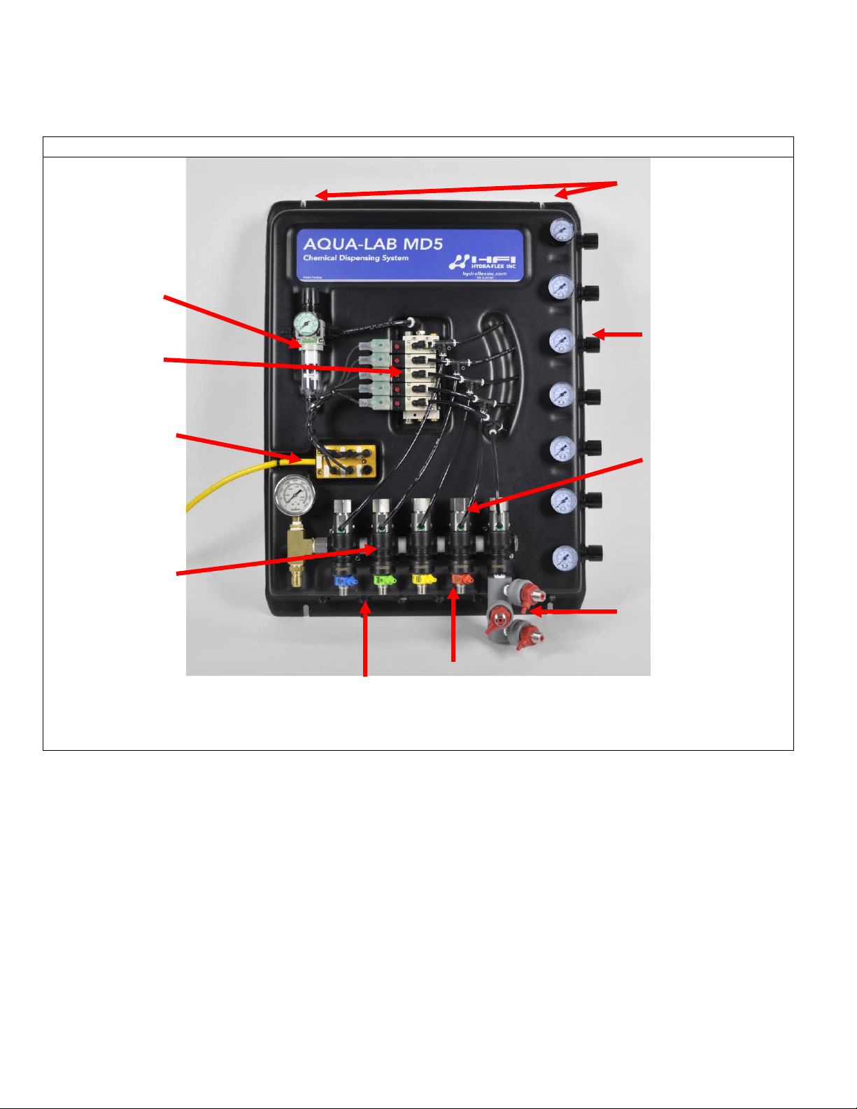
MD5 Panel
Primary Air
Individual Air
Mounting Slots (2
Air Valve
M12 Junction
Hydra-Cannon
Water Ports (front)
Air Ports (back)
Tri-Foam Manifold
Hydra-Cannon
Regulator
Installation Manual
top, 2 bottom)
Regulators
Block
Manifold
Water Valve
(optional)
© Hydra-Flex Inc 2011
Installation Manual
- 3 -
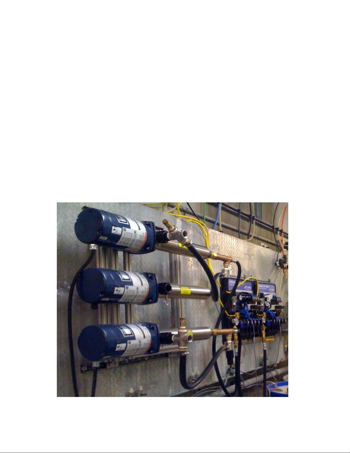
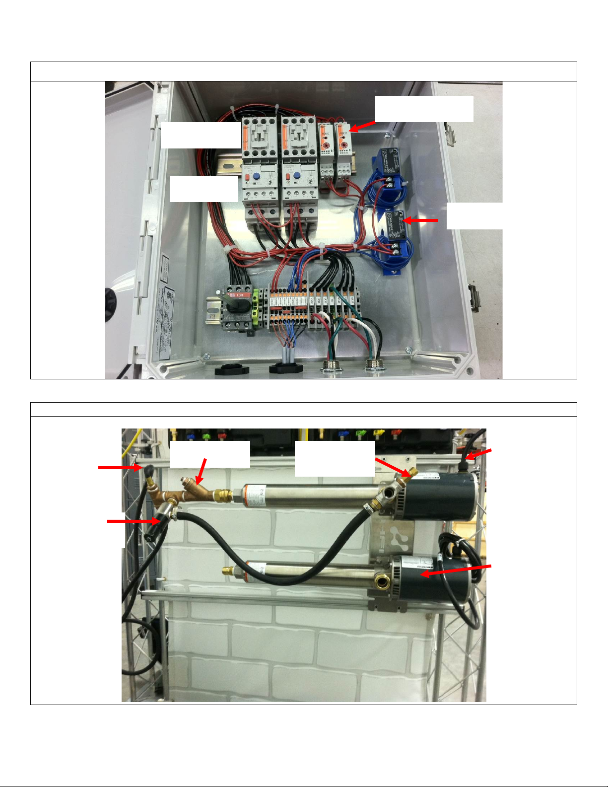
Motor Starter (Dual Source / Dual Pump Shown)
Pump Stand (Single Pump with Back-up show n)
Current Sensor
Timer Relay
Contactor
Overload
Thermal Relief
Pressure
Y-Strainer
Feed lines to
Powerfast cord
Back-up Pump
MD5 panels
Regulator
Valve
(plugs into
bottom of
motor starter)
© Hydra-Flex Inc 2011
 Loading...