

AQUA-LAB™
CS1
Chemical Dispensing System
Installation and
Operation Manual
REV A

Operating Manual
For Additional Support Call:
952.808.3640
Table of Contents
Specifications .......................................................................................................................................... - 1 -
Illustration ............................................................................................................................................... - 1 -
Installation and Set Up ............................................................................................................................ - 2 -
Initial Injector Setup ........................................................................................................................... - 3 -
Injector Vacuum Check (for troubleshooting injectors) ..................................................................... - 5 -
Foaming Prep Setup ............................................................................... Error! Bookmark not defined.
Optimizing the System ............................................................................................................................ - 6 -
Application Optimization (repeat for each application) ..................................................................... - 6 -
Chemical Usage Measuring .................................................................................................................... - 7 -
Recommended Maintenance ................................................................................................................... - 7 -
Troubleshooting ...................................................................................................................................... - 8 -
Appendix ............................................................................................................................................... - 10 -
© Hydra-Flex Inc 2011
Operating Manual
- 1 -
Specifications
1. Operating water pressure: 200 psi (Factory set)
2. Pneumatics operating pressure: 100 psi Max Feed
3. Maximum water source temperature 140° F
4. Operating ambient temperature: 40-120° F
5. Signal – No signal from Car Wash Controller required
6. Electrical supply
a. 120/208-230VAC (1-phase) – 8 foot cord included
b. 3/4 hp pump 10 amps @ 120 volts or 5 amps @ 208 volts
7. Water supply
a. 50 micron filtration or better recommended
b. ½” OD Poly Flow or 3/8” ID Hose
c. Inlet pressure: Flooded-80 psi
i. If pump is fed from tank, water level must be ~28” above pump.
8. Air supply
a. 3/8” feed per system
b. 20 CFM @ 100 psi supply
9. Solution Outlet lines
a. ½” poly lines(3/8” ID)
b. Max pressure of outlet line is 66psi
10. Space requirement: 20” L x 12” W x 16”H
11. Weigh ~45lbs
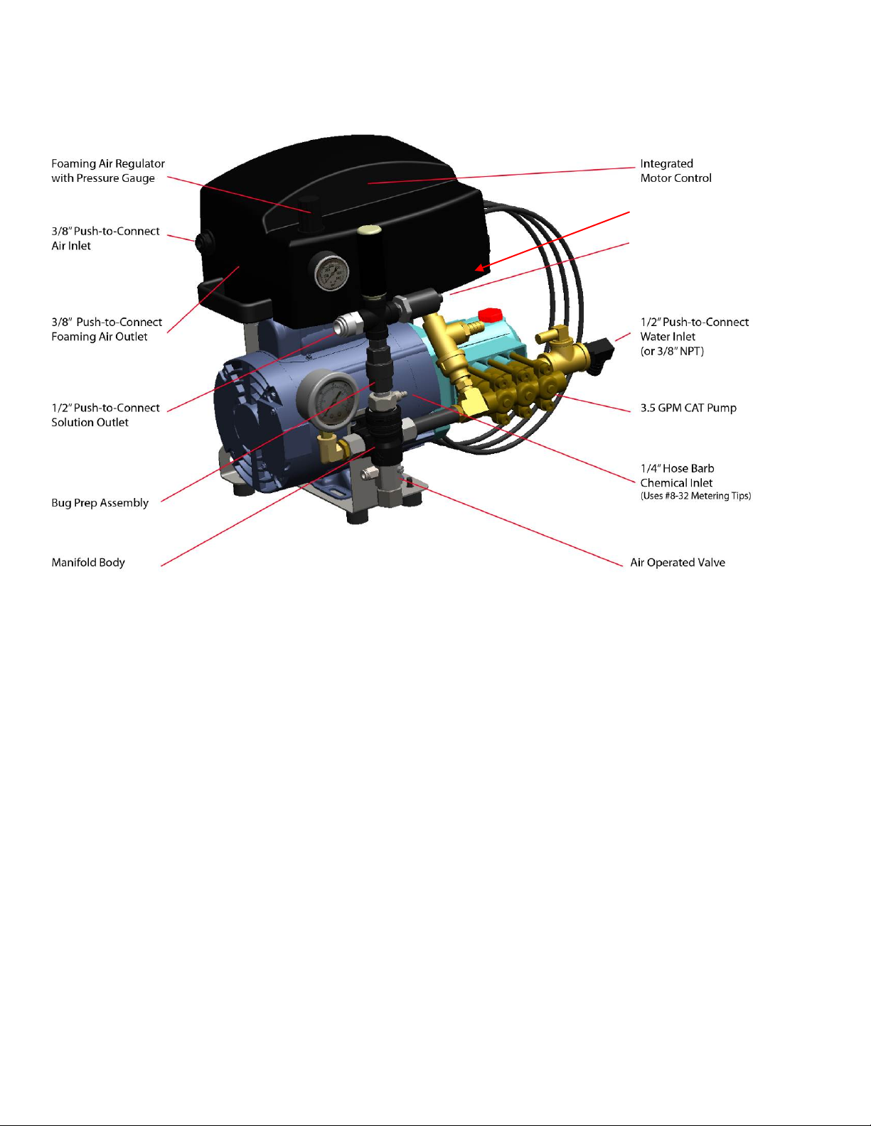
Illustration
© Hydra-Flex Inc 2011
Operating Manual
- 2 -
Adjustable Pressure
Regulator
Installation and Set Up
1. Unpack from crate and inspect for damages
2. Anchor Mounting bracket to the wall in the desired location using three ¼” wall anchors.
a. Make sure that the mounting bracket is level
3. Hang CS1 on mounting bracket
4. Plumb water inlet using attached ½” push to connect fitting or remove and use the 3/8” NPT to adapt to
the fitting of your choice.
5. Plumb the air inlet using 3/8” poly flow hose ( a minimum of 60psi is required to open the valve
properly)
6. Plumb the solution outlet to the desired location using 3/8” poly flow tubing or other hose of your
choice.
7. Optional - Plumb the air outlet tubing using 3/8” poly flow tubing to a convenient location as near the
gun as possible and tee into the solution line and install check valve on the air line.
8. Connect the gun with foam generator to the end of the solution line
9. Plug the 120VAC cord into a dedicated 20 amp plug in
10. Turn the on / off switch on and the system should turn on and pressurize the outlet tubing to the set point
of the pressure switch and turn off
11. Have someone use the gun and monitor the system to make sure that the pump is not cycling un-
necessarily. If it is turning on an off rapidly address one of the three below issues.
© Hydra-Flex Inc 2011
Operating Manual
- 3 -
Size
Nozzle Size
Oriface
Approx.
Pressure
0.029 3 0.043
40
a. Increase the pressure set point of the pressure switch by removing the Phillips head screw and
using a 1/8” hex key or Allen wrench to turn the set screw clockwise, replace the
b. Increase the size of the nozzle on the gun
c. Decrease the size of the injector on the system
12. Make sure that the pressure gage at the manifold is set at 200psi by adjusting the pressure regulator.
a. Make sure to engage the lock nut after adjustment
13. At the end of each day make sure that the system switch is turned off to ensure that the system doesn’t
cycle on and off during the night and will not cause a flood if there is a hose or fitting failure
downstream of the system
Initial Injector Setup
(Based on field experience this is HFI’s recommended staring point)
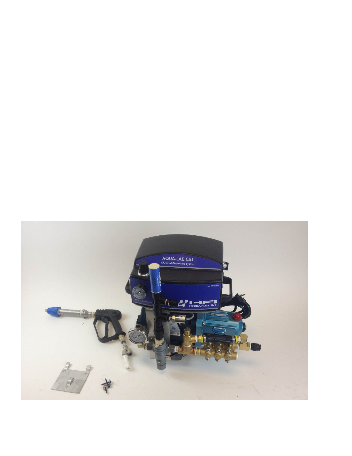
1. All HFI Prep systems ship with an ¾ GPM injector, a foam
generator and a standard spray gun. If you would like to use
the CS1 Prep system without using the foaming feature you
can remove the foam generator and eliminate the air line from
the installation instructions. Please refer to the chart below and
select the injector / nozzle combination that best meets your
needs.
Injector
© Hydra-Flex Inc 2011
Nozzle
Back

Operating Manual
- 4 -
0.029 4 0.052
15
0.04 5 0.057
50
0.04 6 0.062
25
0.04 7 0.067
10
0.051 7 0.067
50
0.051 8 0.072
40
0.051
10
0.08
15
0.057 8 0.072
60
0.057
10
0.08
45
0.057
15
0.096
18
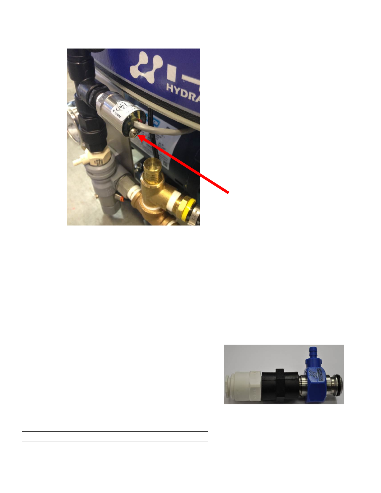
2. Connect solution lines to the bug prep assembly using the attached push connect fitting
a. Do not over tighten poly fittings or they may crack
3. Connect ¼” poly lines from each chemical container to the appropriate injector
a. Ensure a foot valve or similar check valve/filter is installed on each line
i. These must be present or metering tips may clog
4. Metering tips will need to be installed to set dilution ratio (see appendix for ratio charts to determine tip)
If the spray nozzles on the gun is too small for th e injector chosen, the back pressure put on the injector may
cause the injector not to function and chemical will not be pulled. The back pressure should not exceed 66 psi.
Back pressure gauges are available for purchase from HFI. (P/N 1001105) Water will continue to flow as normal.
© Hydra-Flex Inc 2011

Operating Manual
- 5 -
Injector Vacuum Check (for troubleshooting inject ors )
1. At the ChemFlex injector, remove the chemical feed line from the injector hose barb.
2. Attach the tubing of the vacuum gauge to the ChemFlex hose barb
3. With the gun open and the system running an injector that is working properly will have a reading greater than or
equal to (≥) 20 in Hg
4. If injector is not functioning:
a) Check metering tip for clogs (can be tested with no metering tip to ensure injector is performing)
b) Try smaller injector (this will produce less flow and thus less backpressure)
c) Remove a nozzle(s) at the arch, allowing water to free flow (this will reduce backpressure)
There is a variation of performance in the injectors that comes from slight variations in the dimensions of the parts and in assembly that are
unavoidable. It is common to see the resultant vacuum range from 20 in Hg all the way up to 28. There is also variation in the through hole size on the
meter tips fr om Dema (within their manufacturi ng tolerances). Using the same tip color from site to site is a good starting point. However with the
potential for variation from part to part it is reasonable to still need to do some adjustments from there.
© Hydra-Flex Inc 2011

Operating Manual
- 6 -
Optimizing the System
Consistently achieve the desired cleaning and presentation/performance
using the least amount of chemical and water
Injectors vs. Metering Tips vs. Nozzles
The key to optimizing the system is through trial and error.
Don’t be afraid to try these steps to achieve your ideal performance.
What do injectors do?
o Increases or decreases the amount of water
in the solution
What do metering tips do?
o Increases or decreases the amou nt of
chemical in the solution
What do nozzles do?
o Determines the pattern and backpressure of
the solution
Application Optimization (repeat for each application)
View Performance at Gun with Decision Maker
• Application too wet
o Increase air
o Reduce injector size (decreases water)
o Increase metering tip (increases chemical)
• Application too dry
o Decrease air
o Increase injector size (increases water)
o Decrease metering tip (decreases chemical)
• Nozzle sputters
o Decrease air
o Decrease nozzle(s) and/or size used on arch
o Increase injector size (increases water)
• Too much chemical used
o Decrease metering tip
o Decrease metering tip and injector size (to maintain desired ratio)
• No chemical
o Check vacuum of injector (see instructions on page 9)
o Check foot valve
o Check metering tip
• Nozzle fan pattern not filled
o Reduce nozzle size
o Increase injector size (increases water)
• Water not present at all nozzles on arch
o Verify check valves are functioning
o Verify nozzles are not plugged
o Reduce number of nozzles
o Reduce nozzle size
© Hydra-Flex Inc 2011
o Increase injector size (increases water)

Operating Manual
- 7 -
Chemical Usage Measuring
Verify titration of chemicals before proceeding
1. Setup lab scale with small bucket of chemical to be measured.
2. Put the suction line into the bucket.
3. Run the application being tested to “prime” the line. (All air bubbles must be removed for accuracy)
4. Record the Initial Weight from the scale. (Tarring the scale with weight on the scale can affect accuracy)
5. Run the application for 6 vehicles (or manually for the same it would be on for 6 vehicles).
6. Record the Final Weight from the scale.
7. Subtract the Initial Weight from the Final Weight to determine the weight of used product.
8. Divide this Used Weight by 6 to get a per car weight.
9. Divide the Per Car Weight in grams by the specific gravity of the chemical to determine the milliliters of chemical
used per vehicle.
Recommended Maintenance
The recommended service and maintenance on the AQUA-LAB System are as follows.
Monthly
• Check water filter and replace as needed (if installed)
Semi-Annually
• Check and replace injector metering tips
• Clean / check air and water valves
• Check and clean Y strainer (if installed)
• Inspect and replace chemical lines as needed
Annually
• Clean water regulator
• Inspect motor starter for corrosion, if identified order replacement/spare parts
2 Years
• Inspect and replace injectors
• Rebuild valves
• Rebuild water regulator
© Hydra-Flex Inc 2011

- 8 -
Troubleshooting
PROBLEM
POTENTIAL CAUSES SOLUTIONS
Pump not primed
See priming instructions
Inlet Restriction
Check all in-line filters and inlet plumbing for restrictions.
Check valves and backflow preventers
Inadequate water supply
Check pressure on inlet side of pump to be sure positive
pressure is maintained
Undersized piping
Replace with larger piping
Leak on the Inlet side Make sure connections are tight
Worn or defective pump parts Replace worn parts or entire pump, Clean parts if required
Pump check valves cloged
Clean and check all 6 pump check valves
Incorrect Motor rotation
Reverse motor rotation by interchanging any two leads
Blown fuse or circuit breaker
Replaced fuses or close circuit breaker
Defective Motor Starter
contactor
Replaced motor starter contactor
Defective pressure switch Replace pressure switch
Incorrect Motor Voltage Voltage must be within 10% of motor rated voltage
Defective motor Replace motor
Pump components damaged
Replace worn part or entire pump
Not Primed
Reprime pump
Pump not secured firmly
Secure properly
Restricted Inlet Clean or correct restriction
Water regulator fluttering
Try to adjust regulator down and then back up or replace
regulator
Pump check valves cloged
Clean and check all 6 pump check valves
Cavitation (Sounds like marbles
in pump)
Increase inlet size
Pressure Switch set too low Increase set point of pressure switch
Foam generator clogging clean foam generator
Worn mechanical seal Replace shaft seal
Worn o-ring seals Replace
Injector is not
drawing chemical -
Passes Vacuum
Pressure check
Clogged chemical feed
Check chemical hose, foot valve, metering tip and hose barb
for debris or clogs
Too much back pressure on
injector
Perform back pressure check test outlined in Section IV if this
manual. If the result is higher than 66 psi then Increase arch
nozzle size or quantity, use larger tubing, or use a smaller flow
injector
Clogged injector check valve
Blow compressed air through the chemical hose barb on the
injector to remove debris
Clogged injector nozzle Remove injector and blow out any debris with compressed air
Pump won't start or
run at full speed
Pump Operates, but
delivers little or no
water
Injector is not
drawing chemical -
Fails Vacuum
Pressure check
test
Pump Leaks
Excessive Noise from
Pump
Pump cycles on and
off
Operating Manual
© Hydra-Flex Inc 2011

Operating Manual
- 9 -
PROBLEM POTENTIAL CAUSES SOLUTIONS
Pump not primed Follow priming instructions
Debris in regulator Remove regulator and clean out debris
Motor rotation incorrect Verify rotation and adjust wiring to correct
Pump check valves cloged Clean and check all 6 pump check valves
Defective Check Valve Replace check valve if broken
Defective Regulator Replace Regulator
Defective Pump Replace Pump
Incorrect Injector Flow Rate
Selection
Replace with desired injector size
System pressure too low Ensure system pressure is set at 200 psi
Foam Generator Plugged Ensure cleaned and clear
Downstream pluming restrictive
Perform Back pressure test outlined in Section IV of this
manual, if over 66 psi, increase tube size and reduce elbows,
turns or other restrictive plumbing
Solenoid valve malfunction
Ensure valve is receiving the correct electrical signal and
voltage
Valve may be assembled incorrectly
Disassemble valve and clean out debris (See valve
replacement instructions)
Clogged Injector Remove injector and blow out debris with compressed air
No water supply Check that the system has a supply of water
Valve stuck open –
Staying open when
signal is off
O-ring failure Replace O-rings inside valve
Flow at gun is too
low
System won't
regulate up to 200
psi
No flow from injector
© Hydra-Flex Inc 2011

- 10 -
Appendix
Operating Manual
© Hydra-Flex Inc 2011

- 11 -
Chem-Flex Injector Listing
Aqua-Lab Chem Flex Injector Listing
Part Number
#
Barbs
GPM
618029
1
0.25
618040
1
0.50
618051
1
0.75
618057
1
1.00
618070
1
1.50
618083
1
2.00
618086
1
2.30
618098
1
3.20
618125
1
5.40
629029
2
0.25
629040
2
0.50
629051
2
0.75
629057
2
1.00
629070
2
1.50
629083
2
2.00
629086
2
2.30
629098
2
3.20
629125
2
5.40
Operating Manual
© Hydra-Flex Inc 2011

Operating Manual
- 12 -
AQUA-LAB WARRANTY
Factory Limited
Hydra-Flex Inc warrants its equipment to be free from defec t in material or workmanship under proper
normal proper use for a period of one (1) year beginning the date of purchase.
The Hydra-Flex Inc’s liability shall be limited to repair or replacement of parts found to be defective
within the warranty period and following Hydra-Flex Inc’s inspection. Hydra-Flex Inc shall have the
option requiring the return of defective material to establish the purchaser’s claim. In the event of
repair or replacement this limited warranty is non-cumulative. Neither labor nor transportation charges
are included in this warranty.
This warranty is based upon the proper care and maintenance of the warranted equipment. Warranty
does not apply if the merchandise is altered or modified in any way. Warranty does not apply to any
equipment which has been subject to misuse, inappropriate use of tools, including exposure to harsh
chemicals, neglect, lack of maintenance, freezing, fluid hammer, accident, third party damage, fluid
impurities such as sand or miner al s, acts o f God or acts of war. Nor does it apply to any equipment
which has been repaired or altered by anyone not so authorized by Hydra-Flex Inc. All equipment
must be properly installed in accordance with specified plumbing, electrical, and mechanical
requirements. The warranty does not apply to normal wear and tear or routine maintenance
components as described in the equipment manual.
Except as expressly stated herein, Hydra-Flex Inc shall not be liable for damages of any kind in
connection with the purchase, mainten anc e, or use of this equipment including loss of profits and all
claims for consequential damages. This limited warranty is in lieu of all other warranties expressed or
implied. Hydra-Flex Inc neither assumes nor authorizes any person to assume for it any other
obligation or liability in connection herewith. This warranty is neither assignable nor transferable.
Transportation damage claims are to be submitted to the carrier of the damaged material.
© Hydra-Flex Inc 2011
 Loading...