

Page 1
Installation, Operation & Maintenance
177-998D
T100 Series High Pressure
Model: T100S
1204 Chestnut Avenue, Minneapolis, MN 55403
Tel: (612) 332-5681 Fax: (612) 332-6937
Toll-free fax [US only]: (800) 332-6812
www.hydra-cell.com/metering
email: [email protected]
W0542B
Page 2
T100 Series High Pressure - Contents
W0542B
Page
Component Identication ........................................................2
Specications ..........................................................................2
Dimensions .............................................................................4
Installation ...............................................................................6
Maintenance ............................................................................9
Service (Fluid End) ................................................................10
Service (Hydraulic Section) ...................................................11
Service (Power End) .............................................................14
Troubleshooting .....................................................................16
Oil Level Monitor ...................................................................17
Fluid End Parts ......................................................................18
Hydraulic Section Parts ........................................................ 20
Power End Parts .................................................................. 22
Torque Specications ............................................................24
T100S Tool Kit Parts .............................................................25
Pump Storage .......................................................................25
Replacement Parts Kits ....................................................... 26
Warranty ................................................................................27
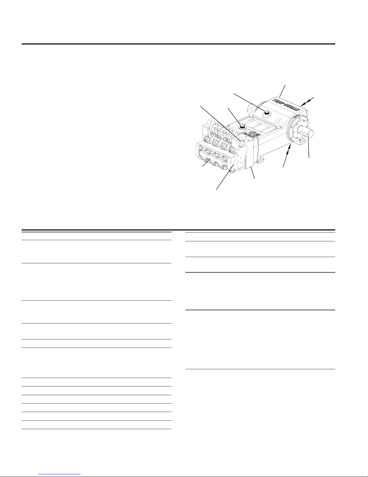
Component Identication
Oil Fill Cap
with Dipstick
Outlet
Fluid End
Oil Fill Cap
Hydraulic Section
Inlet
T100 Series High - Specications
Power End
Float Switch &
Sight Glass
Crankshaft
Oil Drain Plug
Maximum Pressure: 5000 psi (345 bar)
Flow Capacities @ Maximum Pressure
rpm gpm I/min BPD
T100S 450 26.0 98.4 891
Delivery
Pressure psi (bar) gal/rev liter/rev
500 (34) 0.066 0.249
2500 (172) 0.063 0.237
5000 (345) 0.059 0.222
rpm
450 maximum
20 0 m ini mum (contact factory for speeds less than 200)
Maximum Discharge Pressure
Metallic Heads: 5000 psi (345 bar)
Maximum Inlet Pressure 500 psi (34 bar)
Operating Temperature
Maximum: 180 F (82.2 C)
Minimum: 40 F (4.4 C)
(consult factory for temperatures outside this range)
Maximum Solids Size 800 microns
Input Shaft Left or Right Side
Inlet Ports 2 inch Class 300 FF ANSI Flange
Discharge Ports 1-1/4 inch Class 2500 RTJ ANSI Flange
Shaft Diameter 3 inch (76.2 mm)
Shaft Rotation Uni-directional (see rotation arrows)
T100 Series High Specications (Cont’d)
Oil Capacity 18 US quarts (17 liters) - blank back cover
20.5 US quarts (19.4 liters) - oil level back cover
Weight (dry)
Metallic Heads: 1100 lbs (499 kg)
Fluid End Materials
Diaphragm Follower Screw: 316 Stainless Steel
Outlet Valve Retainer: 316 Stainless Steel
Plug-Outlet Valve Port: 316 Stainless Steel
Inlet Valve Retainer: 316 Stainless Steel
Power End Materials
Crankshaft: Forged Q&T Alloy Steel
Connecting Rods: Ductile Iron
Crossheads: 12L14 Steel
Crankcase: Ductile Iron
Bearings: Spherical Roller/Journal (main)
Steel Backed Babbit (crankpin)
Bronze (wristpin)
2
177- 9 9 8 D
Page 3
T100S
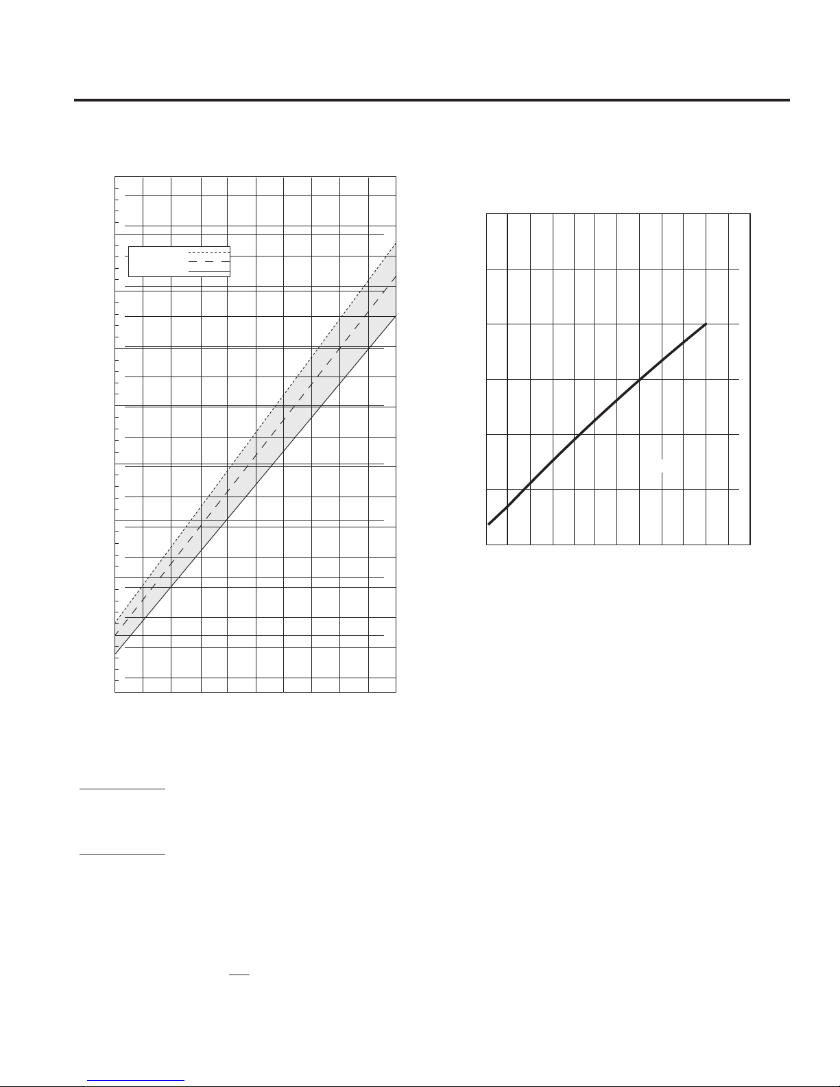
RPM
200 225 325 375 425 450
10.0
32.5
30.0
27.5
25.0
22.5
20.0
17.5
15.0
12.5
Liters Per Minute
Gallons Per Minute
35.9
W0540B
275 400350300250
75.0
80.0
85.0
90.0
95.0
70.0
40.0
45.0
50.0
55.0
60.0
65.0
100.0
110.0
115.0
120.0
105.0
500 psi (34 bar)
2500 psi (172 bar)
5000 psi (345 bar)
RPM
12
NPSHr (feet of water
)
NPSHr (meters of water)
13
14
15
16
17
18
3.75
4
4.25
4.5
4.75
5
5.25
W0541B
5.5
T100S
200 350 450300 400 500250
T100 Series - High Specications (Cont’d)
Performance
Net Positive Suction Head –
NPSHr
Calculating Required
Horsepower (kW)*
gpm x psi
1,460
l/min x bar
* HP/kW is required application power.
Attention!
511
=
electric motor HP*
=
electric motor kW*
When sizing motors with variable speed drives (VFDs), it is
very important to select a motor and a VFD rated for constant
torque inverter duty service and that the motor is rated to
meet the torque requirements of the pump throughout desired
speed range.
3
177- 9 9 8 D
Page 4
T100 Series High Pressure - Dimensions
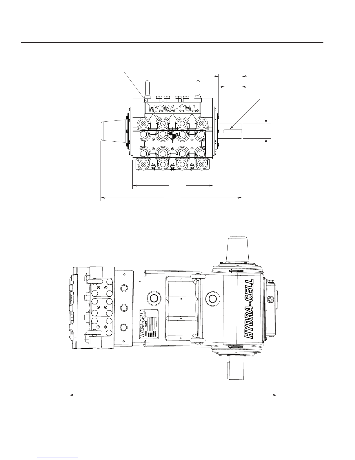
W0529B
3.50
(89)
4.83
(123)
Ø 3.00
(76)
0.75 X 0.75 Keyway
(19.05 X 19.05)
Minimum full key
29.11
(739)
16.50
(419)
Center of mass
42.55 (1081)
W0530B
inches
(mm)
Front View
Top View
4
177- 9 9 8 D
Page 5
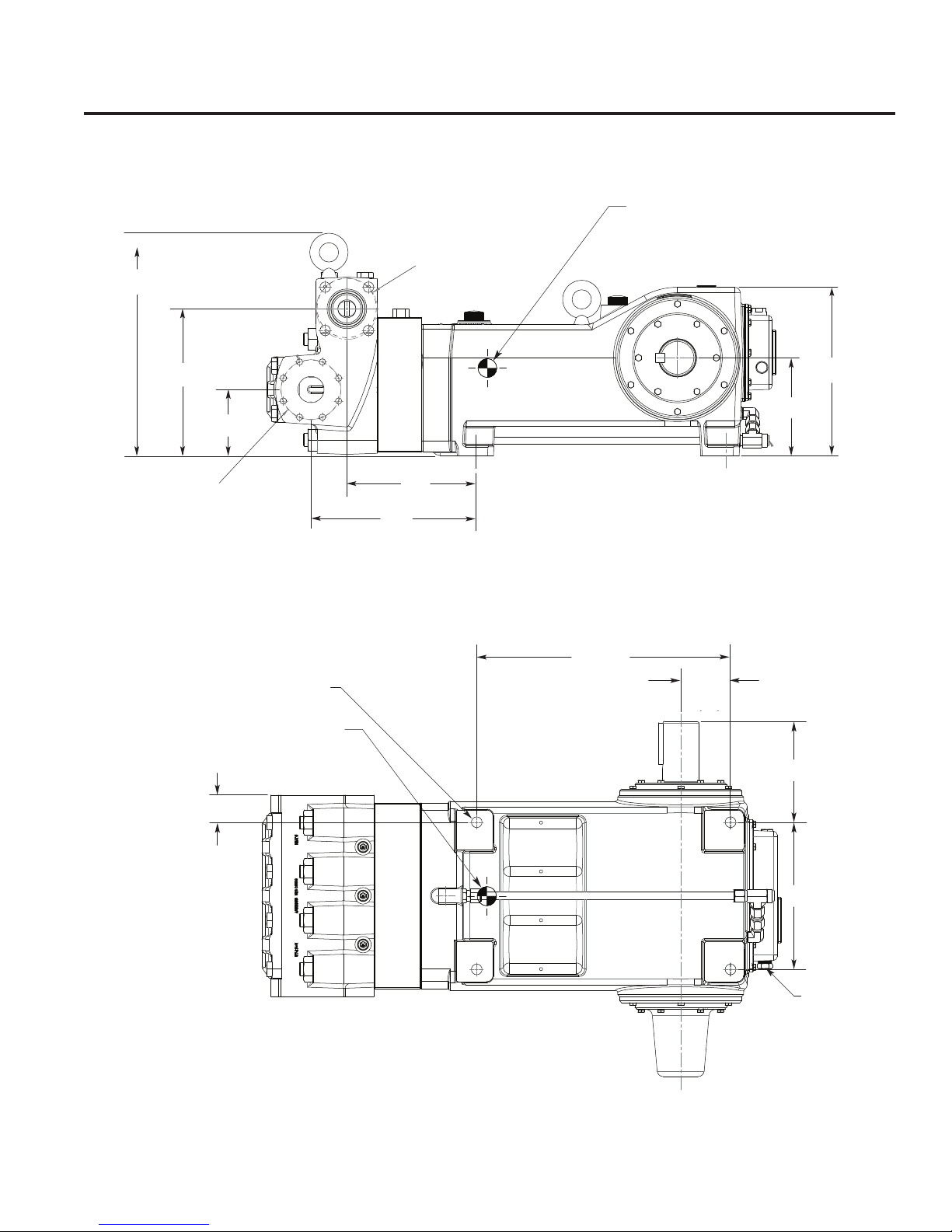
T100 Series High - Dimensions (Cont’d)
Center of mass
Outlet:
ASME 16.5
18.6
(473)
1-1/4˝ Class 2500 lbs RTJ
(4X 1-8 UNC-2B)
Both Sides
inches
(mm)
12.30
(312)
5.54
(141)
Inlet:
ASME B16.5
2˝ Class 300 lbs FF
(8X 5/8-11 UNC-2B)
Both Sides
2.22
(56)
4 X Ø0.88
(22.23)
Mounting Holes
Center of mass
13.92
(354)
10.92
(277)
Side View
20.80
(528)
W0531B
4.09
(104)
8.2
(208)
8.27
(210)
14.1
(358)
Bottom View
5
W0532B
12.06
(306)
3/4-14 NPT
177- 9 9 8 D
Page 6
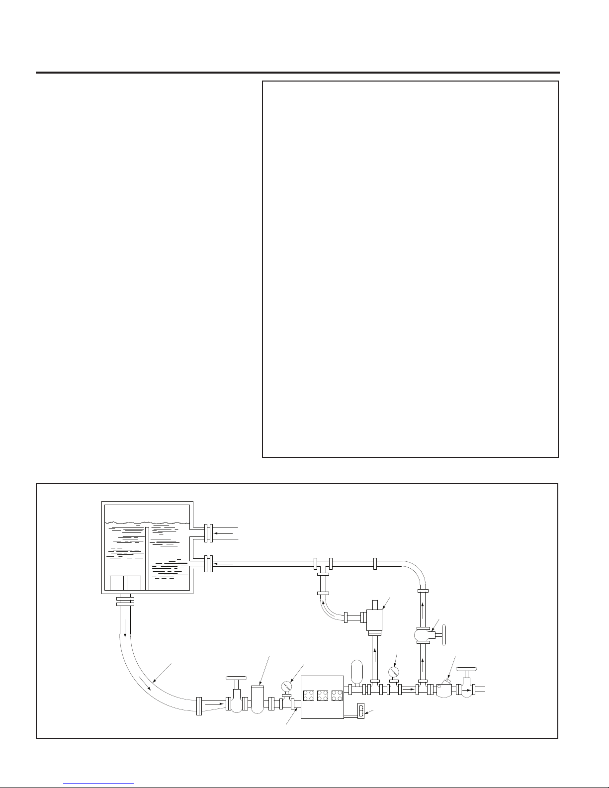
T100 Series High Pressure - Installation
MINIMUM LIQUID LEVEL
VORTEX
BREAKER
WEIR
PLATE
FEED IN
LINE VELOCITY
5-15 FT/SEC.
LONG-RADIUS
ELBOW
SUCTION LINE
VELOCITY 1-3 FT/SEC.
FULL-OPENING
VALV E
ECCENTRIC REDUCER
W/ FLAT SIDE UP
(OPTIONAL)
SUCTION
STABILIZER
AMPLE NPSHA
PUMP FLUID
CYLINDER
LINE VELOCITY
3-10 FT/SEC.
MINIMUM NUMBER OF ELBOWS
WITH AMPLE PIPE SUPPORTS
(OPTIONAL)
PULSATION
DAMPENER
RELIEF VALVE W/
10 PERCENT MAX.
PRESSURE
ACCUMULATION
PRESSURE
GAUGE
PRESSURE
GAUGE
Typical Installation
START-UP AND
CAPACITY-CONTROL
VALV E
W0511A
CHECK VALVE
65 psi cracking pressure
OIL LEVEL
MONITOR
Location
Locate the pump as close to the uid supply source as
possible.
Install it in a lighted clean space where it will be easy
to inspect and maintain. Allow room for checking the oil
level, changing the oil (drain plug on the bottom of pump),
and removing the pump head components (inlet and
discharge retainer plates, manifold, and related items).
Rigging Provisions and
Procedures
Lift pump by attaching rigging to all four eyebolts (14).
Adjust attachment lengths to keep pump level during lifting.
CA UTION: Ey e b o l t s ar e ra t e d to lif t th e we i g h t of the
pump only. Also see center of mass references in
the Dimension Drawings Section.
Mounting
CAUTION: The pump shaft rotation direction is
indicated by arrows on the pump housing.
To prevent vibration, mount the pump and motor securely
on a level rigid base.
On a belt-drive system, align the sheaves accurately;
poor alignment wastes horsepower and shortens the
belt and bearing life. Make sure the belts are properly
tightened, as specied by the belt manufacturer.
On a direct-drive system, align the shafts accurately.
Unless otherwise specied by the coupling manufacturer,
maximum parallel misalignment should not exceed 0.015
in. (0.4 mm) and angular misalignment should be held
to 1° maximum. Careful alignment extends life of the
coupling, pump, shafts, and support bearings. Consult
coupling manufacturer for exact alignment tolerances.
Important Precautions
Adequate Fluid Supply. To avoid cavitation and premature pump failure,
be sure that the pump will have an adequate uid supply and that the inlet
line will not be obstructed. See “Inlet Piping” and consult NPSH chart.
Positive Displacement. This is a positive-displacement pump. Install a
relief valve downstream from the pump. See “Discharge Piping”.
Safety Guards. Install adequate safety guards over all pulleys, belts, and
couplings. Follow all local codes and regulations regarding installation
and operation of the pumping system.
Shut- O Valves. Never install shut-o valves between the pump and
discharge pressure regulator, relief valve, or in the regulator bypass line.
Freezing Conditions. Protect the pump from freezing. See also the
Maintenance Section.
Vacuum at Outlet. Do not allow a vacuum at the pump outlet during
shutdown. A vacuum can damage the diaphragm at start-up. If there is a
vacuum at the pump outlet, allow atmospheric pressure at the outlet for
30 minutes before starting. Wanner Engineering recommends installing
an outlet check valve with a 65 psi (4.5 bar) cracking pressure to prevent
a vacuum condition during shutdown.
Consult the Factory for the following situations:
• Fluid temperature applications – above 180° F (82° C) or below 40° F (4.4° C)
• Pressure feeding of pumps over 500 psig (34.5 bar)
• Viscous uid applications above 100 Cps
• Chemical compatibility problems
• Hot ambient temperatures – above 110° F (43° C)
• Conditions where pump oil may exceed 200° F (93° C) because of a
combination of hot ambient temperatures, hot uid temperature, and
full horsepower load — an oil cooler may be required
• Pump rpm less than 200
6
177- 9 9 8 D
Page 7

T100 Series High - Installation (Cont’d)
Accessories
Consult installation drawing below for typical system components.
Contact Wanner Engineering or the distributor in your area for
more details.
Inlet Piping (Suction Feed)
Install drain cocks at any low points of the suction line, to permit
draining in freezing conditions.
Provide for permanent or temporary installation of a vacuum
gauge to monitor the inlet suction. To maintain maximum ow,
NPSHA must exceed NPSHR (See chart in Specications
Section). D o no t supply more than one pump fr o m th e sa m e
inlet line if possible.
Supply Tank
Use a supply tank that is large enough to provide time for any
trapped air in the uid to escape. The tank size should be at
least ve times the maximum pump ow rate (in gpm or lpm).
For example: at a maximum rate of 45 gpm, since trapped air
takes ve minutes to escape from water, 5 x 45 = 225 gallons
for a recommended supply tank size.
Isolate the pump and motor stand from the supply tank, and
support them separately.
Install a separate inlet line from the supply tank to each pump.
Install the inlet and bypass lines so they empty into the supply
tank below the lowest water level, on the opposite side of the
bae from the pump suction line.
If a line strainer is used in the system install it in the inlet line
to the supply tank.
To reduce aeration and turbulence, install a completely submerged
bae plate to separate the incoming and outgoing liquids.
Install a vortex breaker in the supply tank, over the outlet port
to the pump.
Place a cover over the supply tank, to prevent foreign objects
from falling into it.
Hose and Routing
Size the suction line at least one size larger than the pump inlet,
and so that the velocity will be 1-3 ft/sec (0.3 to 0.9 m/s):
For pipe in inches: Velocity (ft/sec) = 0.408 x GPM/Pipe ID2
For pipe in mm: Velocity (m/sec) = 21.2 x LPM/Pipe ID2
Keep the suction line as short and direct as possible.
Use exible hose and/or expansion joints to absorb vibration,
expansion, or contraction.
If possible, keep suction line level. Do not have any high points
collecting vapor unless high points are vented.
To reduce turbulence and resistance, do not use 90° elbows.
If turns are necessary in the suction line, use 45° elbows or
arrange sweeping curves in the exible inlet hose.
If a block valve is used, be sure it is fully opened so that the ow
to the pump is not restricted. The opening should be at least the
same diameter as the inlet plumbing ID.
Do not use a line strainer or lter in the suction line unless
regular maintenance is assured. If used, choose a top loading
basket. It should have a free-ow area of at least three times
the free-ow area of the inlet.
Install piping supports where necessary to relieve strain on the
inlet line and to minimize vibration.
Inlet Piping (Pressure Feed)
Provide for permanent or temporary installation of a vacuum/
pressure gauge to monitor the inlet vacuum or pressure.
Pressure at the pump inlet should not exceed 500 psi (34.5 bar);
if it could get higher, install an inlet pressure reducing regulator.
Do no t su p p l y more than one pu m p fr o m th e same inlet li n e .
Inlet Calculations
Acceleration Head
Calculating the Acceleration Head
Use the following formula to calculate acceleration head losses.
Subtract this gure from the NPSHa, and compare the result to
the NPSHr of the Hydra-Cell pump.
Ha = (L x V x N x C) ÷ (K x G)
where:
Ha = Acceleration head (ft of liquid)
L = Actual length of suction line (ft) — not equivalent length
V = Velocity of liquid in suction line (ft/sec) [V = GPM x (0.408
÷ pipe ID
N = RPM of crank shaft
C = Constant determined by type of pump — use 0.066 for
the T100S Hydra-Cell pumps
K = Constant to compensate for compressibility of the uid —
use: 1.4 for de-aerated or hot water; 1.5 for most liquids;
2.5 for hydrocarbons with high compressibility
G = Gravitational constant (32.2 ft /sec
Friction Losses
Calculating Friction Losses in Suction Piping
When following the above recommendations (under “Inlet
Piping”) for minimum hose/pipe I. D. and maximum length,
frictional losses in the suction piping are negligible (i.e., Hf = 0)
if you are pumping a water-like uid.
When pumping more-viscous uids such as lubricating oils,
sealants, adhesives, syrups, varnishes, etc., frictional losses in
the su c t i o n piping ma y bec ome signi c an t . As Hf increase s , th e
available NPSH (NPSHa) will decrease, and cavitation will occur.
In general, frictional losses increase with increasing viscosity,
increasing suction-line length, increasing pump ow rate, and
decreasing suction-line diameter. Changes in suction-line
diameter have the greatest impact on frictional losses: a 25%
increase in suction-line diameter cuts losses by more than two
times, and a 50% increase cuts losses by a factor of ve times.
Consult the factory before pumping viscous uids.
Minimizing Acceleration Head and Frictional Losses
To minimize the acceleration head and frictional losses:
• Keep inlet lines less than 6 ft (1.8 m) or as short as possible
2
)]
2
)
7
177- 9 9 8 D
Page 8

T100 Series High - Installation (Cont’d)
• Use at least 2.5 in. (63 mm) I.D. inlet hose
• Use suction hose (low-pressure hose, non collapsing) for
the inlet lines
• Minimize ttings (elbows, valves, tees, etc.)
• Use a suction stabilizer on the inlet.
Net Positive Suction Head
NPSHa must be equal to or greater than NPSHr. If not, the
pressure in the pump inlet will be lower than the vapor pressure
of the uid — and cavitation will occur.
Calculating the NPSHa
Use the following formula to calculate the NPSHa:
NPSHa = Pt + Hz - Hf - Ha - Pvp
where:
Pt = Atmospheric pressure
Hz = Vertical distance from liquid surface to pump center line
(if liquid is below pump center line, the Hz is negative)
Hf = Friction losses in suction piping
Ha = Acceleration head at pump suction
Pvp = Absolute vapor pressure of liquid at pumping temperature
Notes:
• In good practice, NPSHa should be 2 ft greater than NPSHr
• All values must be expressed in feet of liquid
Atmospheric Pressure at Various Altitudes
Altitude Pressure Altitude Pressure
(ft) (ft of H
0 33.9 1500 32.1
500 33.3 2000 31.5
1000 32.8 5000 28.2
O) (ft) (ft of H2O)
2
Discharge Piping
Hose and Routing
Use the shortest, most-direct route for the discharge line.
Select pipe or hose with a working pressure rating of at least
1.5 times the maximum system pressure. EX AMPLE: Select
a 1500 psi W.P.-rated hose for systems to be operated at 1000
psi-gauge pressure.
Use exible hose between the pump and rigid piping to absorb
vibration, expansion or contraction.
Support the pump and piping independently. Size the discharge line
so that the velocity of the uid will be 3-10 ft/sec (1-3 m/sec):
For pipe in inches: Velocity (ft/sec) = 0.408 x GPM/Pipe ID2
2
For pipe in mm: Velocity (m/sec) = 21.2 x LPM/Pipe ID
Pressure Relief
In stal l a pressure relie f val ve in th e disc harg e line . Bypass
pressure must not exceed the pressure limit of the pump.
Size the relief valve so that, when fully open, it will be large
enough to relieve the full capacity of the pump without
overpressurizing the system.
Locate the valve as close to the pump as possible and ahead
of any other valves.
Adjust the pressure relief valve to no more than 10% over the
maximum working pressure of the system.
Route the bypass line to the supply tank. See the diagram showing
a typical installation at the beginning of the Installation Section.
If the pump may be run for a long time with the discharge closed
and uid bypassing, install a thermal protector in the bypass line
(to prevent severe temperature buildup in the bypassed uid).
CAUTION: Never install shuto valves in the bypass line
or between the pump and pressure relief valve.
Install a pressure gauge in the discharge line.
Va c uum at Ou t l e t . Do not allow a vacuum at the pump outlet during
shutdown. A vacuum can damage the diaphragm at start-up. If
there is a vacuum at the pump outlet, allow atmospheric pressure
at the outlet for 30 minutes before starting. Wanner Engineering
recommends installing an outlet check valve with a 65 psi cracking
pressure to prevent a vacuum condition during shutdown.
Oil Level Monitoring. Oil level is sensed by the back cover
oat switch (48) and can be used to control the pump system
operation.
Before Initial Start-Up
Before you start the pump, be sure that:
• Pump is stored at a temperature between 40-180 F (4.4-82.2 C)
for a minimum of 24 hours before start up.
• All shuto valves are open, and the pump has an adequate
supply of uid.
• All connections are tight.
• The oil level is within the marking on the dipstick. Add oil as
needed. The oil level can also be viewed through the sight
glass (42) on the back cover (12). The oil level is OK when
the oat (48) is in the middle of the sight glass.
• Connect the oat switch (if used). See Float Switch Section.
• Test the oat switch by removing the side port plug (50) and
manipulating the oat up and down using a suitable tool
(screwdriver). Reinstall side port plug (50).
CAUTION: Take care not to drop tool inside pump.
• The relief valve on the pump outlet is adjusted so the pump
starts under minimum pressure.
• All shaft couplings or drive pulleys have adequate safety guards.
Initial Start-Up
1. Pump must be at or above 40 F (4.4 C) for 24 hours prior to
starting.
2. Open the bypass line start-up and capacity-control valve so the
pump may be started against negligible discharge pressure.
3. Turn on power to the pump motor.
4. Ch e c k the inlet pressure or va c u um. To maint a i n maximu m ow,
inlet vacuum must not exceed 7 in. Hg at 70° F (180 mm Hg at
21° C). Inlet pressure must not exceed 500 psi (34.5 bar).
5. Listen for any erratic noise, and look for unsteady ow. If the
pump does not clear, refer to the Troubleshooting Section.
6. If the system has an air lock and the pump fails to prime:
a. Turn o the power.
b. Remove the pressure gauge from the tee tting at the
pump outlet (see installation diagram).
8
177- 9 9 8 D
Page 9

T100 Series High - Installation/Maintenance
Initial Start-Up (Cont’d)
Note: Fluid may come out of this port when the plug
is removed. Provide an adequate catch basin for uid
spillage, if required. Fluid will come out of this port
when the pump is started, so we recommend that you
attach adequate plumbing from this port so uid will
not be sprayed or lost. Use high-pressure-rated hose
and ttings from this por t. Take all safety precautions
to assure safe handling of the uid being pumped.
c. Jog the system on and o until the uid coming from this
port is air-free.
d. Turn o the power.
e. Remove the plumbing that was temporarily installed, and
reinstall the pressure gauge or plug.
7. Adjust the bypass line valve to the desired operating pressure.
Do not exceed the maximum pressure rating of the pump.
8. After the system pressure is adjusted, verify the safety relief
valve setting by closing the bypass line valve until the relief
valve opens.
Note: Fluid may come out of the safety relief valve.
Provide an adequate catch basin for uid spillage. Take
all safety precautions to assure safe handling of the
spillage.
9. Reset the bypass line valve to obtain the desired system pressure.
10. Provide a return line from the relief valve to the supply tank,
similar to the bypass line.
Maintenance
Note: The numbers in parentheses are the Reference
Numbers shown in the Parts Section of the manual.
Daily
Check the oil level and the condition of the oil with the pump
turned o. The oil level should be within the marking on the
dipstick or when the oat is in the middle of the sight glass. Add
oil as needed or use continuous monitor.
Use the appropriate Hydra-Oil for the application (contact
Wanner Engineering if in doubt).
CAUTION: If you are losing oil but don’t see any external
leakage, or if the oil becomes discolored and contaminated,
one of the diaphragms (73) may be damaged. Refer to the
Fluid-End Service Section. Do not operate the pump with
a damaged diaphragm.
Do no t le a ve contaminated oil in th e pu m p ho u sing or leav e
the housing empty. Remove contaminated oil as soon as
discovered, and replace it with clean oil.
Periodically
Change the oil after the rst 500 hours of operation;
and then every 2000 hours or six months, whichever
comes rst.
Note: Hydra-Cell T100S Series Pumps come standard with
10W30 motor oil.
Minimum oil viscosity for proper hydraulic end lubrication
is 10-20 cST at 212°F (100°C).
Use of an oil cooler is recommended when process uid
and/or hydraulic end oil exceeds 180°F (82°C).
When changing oil, remove drain plug (40) at the bottom of the
pump so all oil and accumulated sediment will drain out.
Check the inlet pressure or vacuum periodically with a gauge. If
vacuum at the pump inlet exceeds NPSHR, check the inlet piping
system for blockages. If the pump inlet is located above the
su p p l y tank, chec k th e u i d supply le vel and re p l enish if to o lo w.
Inspect pump for hydraulic oil or process uid leaks.
Shutdown Procedure During
Freezing Temperatures
Take all safety precautions to assure safe handling of the
ui d be i n g pu m p e d . Prov i d e ad e q u a t e ca t c h basins for u i d
drainage and use appropriate plumbing from drain ports,
etc., wh e n u shing the pump an d system with a co m p a t i b l e
antifreeze. Drain ports are located in the manifold.
Recommended Tools and
Supplies
The following tools and supplies are recommended for servicing
the T100S Pump:
10 mm hex socket with extension
30 mm hex socket
46 mm hex socket
3/4 in. hex socket
8 mm box-end wrench
13 mm open-end wrench
9/16 in. box-end wrench
3 mm hex wrench
4 mm hex wrench
6 mm hex wrench
8 mm hex wrench
3/8 in. hex wrench
Torx T30
Flathead screwdriver
No. 3 Phillips-head screwdriver
Internal retaining ring pliers
8 in. adjustable wrench
Torque wrench, adjustable from 250 to 450 ft-lbs (339 to 610 N-m)
Pipe wrench
Loctite 242
New Hydra-Oil
Wanner T100S Tool Kit (see T100S Tool Kit Parts)
9
177- 9 9 8 D
Page 10

T100 Series High - Fluid End Service
This section explains how to disassemble and inspect all easilyserviceable parts of the pump.
Note: The numbers in parentheses are the Reference
Numbers shown in the Parts Section of the manual.
Fluid End Service
Inlet Check Valve Disassembly
a. See Fluid End Parts View. Remove eight bolts (101) around
inlet retainer plate (91).
b. Remove inlet retainer plate and inlet retainer plugs (89) with
three assembled O-rings (90).
c. Check O-rings and inlet retainer plugs for wear. Replace
if worn. Lubricate new O-rings with petroleum jelly or
lubricating gel. Each inlet retainer plug is attached to inlet
retainer plate with two screws (97).
d. Inspect inlet retainer plate for warping or wear around
inlet ports. Look for corrosion, scale and wear. If wear is
excessive, replace inlet retainer plate. Clean inlet retainer
plate of any scale and corrosion with Scotch-Brite™ pad
or ne emery cloth. Wash after cleaning. To check if inlet
retainer plate is warped, place a straightedge across it. A
warped inlet retainer plate should be replaced.
e. Remove three inlet check valve cartridges (102-107) with
check valve extraction tool. Tool is included in Wanner Tool
Kit.
f. Inspect each of three check valve cartridges for wear and
leakage at seat. Replace inlet check valve cartridges as
needed.
g. Using a light, visually inspect diaphragms through inlet ports.
If diaphragms appear abnormal or damaged, remove and
replace as instructed in Diaphragm Parts Disassembly.
Inlet Check Valve Assembly
a. Reinstall three inlet check valve cartridges.
b. Reinstall inlet retainer plate (91) and inlet retainer plugs
(89) with two screws (97) and assembled O-rings (90).
Use eight bolts (101) to fasten inlet retainer plate. Hand
thread bolts, then tighten from inner to outer. See Manifold
Assembly Torque Sequence Diagram. Torque to 300 ft-lbs
(407 N - m).
Outlet Check Valve Disassembly
Note: Removal of In l e t Check Val ves rst will make re m oval
of Outlet Check Valves easier.
a. Remove two eyebolts (14) and ten cap screws (98) around
three discharge retainer plates (96).
b. Remove three discharge retainer plates with assembled
outlet valve port plugs (93), backup rings (95), O-rings (94),
and outlet valve retainers (92).
c. Check outlet valve port plugs, backup rings, O-rings, and
outlet valve retainers for wear. Replace if worn. Lubricate
new O-rings with petroleum jelly or lubricating gel. Outlet
valve port plugs are attached to discharge retainers plate
with two screws (97).
d. Inspect discharge retainer plates for warping or wear around
discharge ports. Look for corrosion, scale and wear. If
wear is excessive, replace discharge retainer plate. Clean
discharge retainer plates of any scale and corrosion with
Scotch-Brite™ pad or ne emery cloth. Wash after cleaning.
To check if discharge retainer plate is warped, place a
straightedge across it. A warped discharge retainer plate
should be replaced.
e. Remove three outlet check valve cartridges (102-107) with
check valve extraction tool. Tool is included in Wanner Tool
Kit.
f. Inspect each of three check valve cartridges for wear and
leakage at seat. Replace outlet check valve cartridges as
needed.
Outlet Check Valve Assembly
a. Reinstall three outlet check valve cartridges.
b. Reinstall three discharge retainer plates (96) with assembled
outlet valve port plugs (93) with two screws (97) [Torque
to 75 in-lbs (8 N-m)], backup rings (95), O-rings (94), and
outlet valve retainers (92) using ten cap screws (98) and two
eyebolts (14). (Check illustration) Hand thread cap screws
and eyebolts.
c. Tighten cap screws from opposing corners to opposing
corners of discharge retainer plates. Torque to 300 ft-lbs
(407 N - m).
d. Tighten eyebolts with crow bar or hammer.
Drain Plug
a. Remove and replace drain plug (99) and O-ring (100) as
needed. Torque drain plug with O-ring to 40 ft-lbs (54 N-m).
Apply Loctite nickel anti-seize lubricant to thread and chamfer
of plug, with coverage on O-ring.
10
177- 9 9 8 D
Page 11
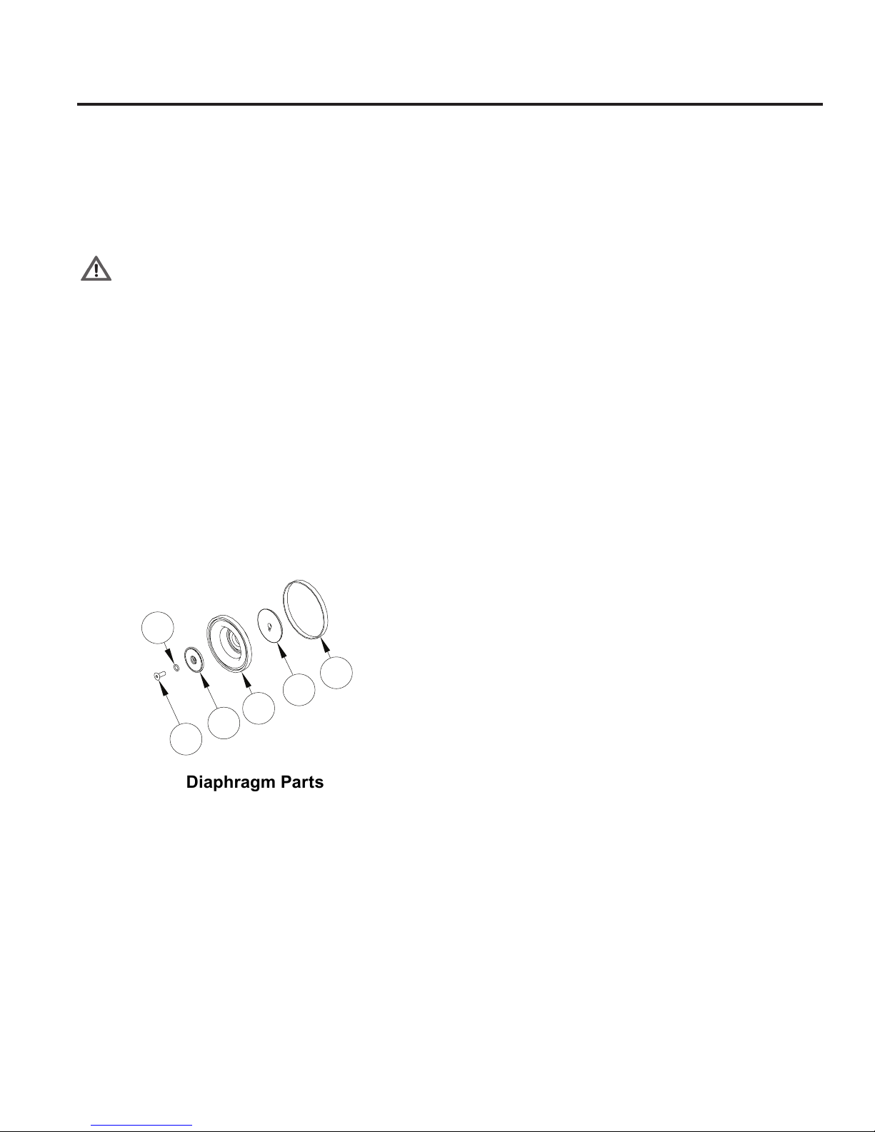
T100 High - Hydraulic Section Service
W0536C
74
73
82
75
84
85
Diaphragm Parts
Note: The numbers in parentheses are the Reference
Numbers shown in the Parts Section of the manual.
Hydraulic Section
Disassembly
Manifold Disassembly
WA R N I N G: Manifold (8 8 ) and assembled part s weigh
over 200 pounds (91 kg) and are a two man lift. Use
care in ha n d l ing to prev e nt personal in j u r y or da m a g e
to equipment.
a. See Power End Parts Illustration in Parts List. Remove drain
plug (40) from bottom of pump and drain oil into container
(capable of holding 20.5 qts [19.4 liters] of oil). Dispose of
old oil in an approved way.
b. Replace drain plugs.
c. See Fluid End Parts View. Remove eight bolts (101) around
inlet retainer plate (91).
d. Remove eight hex nuts (26) from uid end of pump. Install
four 177-393 Extender Studs from T100S Tool Kit on studs
(20). Carefully slide manifold (88) forward along extender
studs to allow access to diaphragm plate (52).
c. Remove the diaphragm (73), and inspect it carefully for
any abnormal conditions. A ruptured diaphragm generally
indicates a pumping system problem, and replacing only
the diaphragm will not solve the larger problem. Inspect the
diaphragm for the following:
• Small puncture. Usually caused by a sharp foreign object
in the uid.
• Diaphragm pulled away from the center screw or from
the cylinder sides. Usually caused by uid being frozen
in the pump, or by overpressurization of the pump.
• Diaphragm becoming sti and losing exibility. Usually
caused by pumping a uid that is incompatible with the
diaphragm material.
• Slice in ridge of diaphragm. Occurs when diaphragm
is operated at cold temperatures.
• Diaphragm torn concentrically in the mid convolute
area. Usually an indication of an outlet vacuum condition.
d. If needed replace diaphragm.
e. Replace diaphragm ring if needed.
Diaphragm Disassembly
a. See Diaphragm Parts and Hydraulic Section Views. Remove
manifold assembly following steps a. through d. above.
b. Manually pull diaphragm (73) forward to expose cross
hole in bias rod (76). Insert 1/8 inch hex wrench through
hole to restrain the bias rod from rotating.
c. Remove screw (74), o-ring (85), and follower (84) which
attaches diaphragm (73), diaphragm clamp (82), and
diaphragm ring (75).
CAUTION: If a diaphragm has ruptured and foreign
material or water has entered the oil reser voir, do not
operate the pump. Ch e c k al l diaphragms, then ush the
reservoir completely and rell it with fresh oil. Never
let the pump stand with foreign material or water in the
reservoir, or with the reservoir empty.
11
177- 9 9 8 D
Page 12
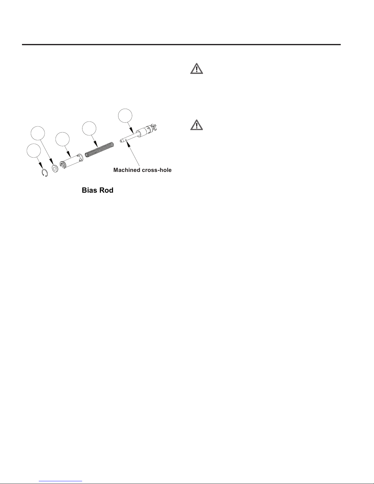
T100 High - Hydraulic Section Service (Cont’d)
Machined cross-hole
Bias Rod
Hydraulic Section
Disassembly (Cont’d)
Bias Rod Disassembly
76
87
81
83
a. See Bias Rod, Diaphragm Parts, and Hydraulic Section Parts
Views. Remove diaphragm (73) as in steps a. through c.
above.
Note: Diaphragm clamp (82) may remain pressed on
bias rod.
b. Reinstall screw (74) and remove hex wrench. Let bias
spring (80) snap assembly to diaphragm plate. Diaphragm
clamp will pop o bias rod.
c. Check diaphragm clamp for any rough surfaces, edges, or
corrosion. Replace if necessary.
d. Using snap-ring pliers, extract internal retainer ring (83).
e. Remove bias rod: bias spring spacer (87), spool travel
limiter (81), and bias spring (80).
CAUTION: Do not attempt to disassemble diaphragm
rod su b a s s e m b l y (76). If rod subassembl y is damaged,
entire subassembly must be replaced.
f. Remove diaphragm rod subassembly (76) as one piece.
Inspect rod subassembly. Smooth surfaces and edges as
necessary with emery cloth or ne le. If necessary, replace.
80
W0537C
Diaphragm Plate Disassembly
WA R N I N G: Manifold (8 8 ) and assembled part s weigh
over 200 pounds and are a two man lift. Use care in
handling to prevent personal injury or damage to
equipment.
a. Slide manifold assembly away from diaphragm plate (52),
following steps a. through d. in the Remove Manifold
Assembly Section.
WARNING: Diaphragm plate (52) and assembled
parts weigh over 100 pounds and are a two man lift.
Use care in handling to prevent personal injury or
damage to equipment.
Note: To ease handling of diaphragm plate, install
two Eyebolts (177-058) from T100 High Pressure
Tool Kit in place of two Setscrews (56) on top of
diaphragm plate.
b. See Hydraulic Section Parts View. Remove two cap
screws (59) from diaphragm plate (52).
c. Carefully slide diaphragm plate and assembled parts away
from pump along pump studs.
d. Replace diaphragm plate gasket (24) if damaged.
Check/Replace Airbleed Valve
a. See Hydraulic Section Rear View. Unthread airbleed
valve (65) from diaphragm plate (52). Inspect valve and
replace if needed.
b. Reinstall airbleed valve. Torque to 75 ft-lbs (102 N-m).
Check/Replace Underll Valve
a. See Hydraulic Section Rear View. Unthread underfill
valve (66) from bottom of diaphragm plate (52). Inspect
valve and replace if needed.
b. Reinstall underll valve. Torque to 30 ft-lbs (41 N-m).
Check/Replace Overll Valve Assembly
a. See Hydraulic Section Rear View. Unthread overfill
valve (69) from bottom of diaphragm plate (52). Inspect
overll valve and replace if needed.
b. Reinstall overll valve. Torque to 105 in-lbs (12 N-m).
12
177- 9 9 8 D
Page 13
T100 High - Hydraulic Section Service (Cont’d)
Hydraulic Section Assembly
Diaphragm Plate Assembly
WARNING: Diaphragm plate (52) and assembled parts
weigh over 100 pounds (45 kg) and are a two man lift.
Use care in handling to prevent personal injury or
damage to equipment.
Note: To ease handling of diaphragm plate, install
two Eyebolts (177-058) from T100S Tool Kit in place
of two Setscrews (56) on top of diaphragm plate.
a. Replace diaphragm plate gasket (24) if damaged.
CAUTION: Ensure plungers (53) are lubricated with oil
before assembly. Dry plungers and cylinders can bind
on start-up.
b. See Hydraulic Section Par ts Illustration. Carefully slide
diaphragm plate (52) and assembled parts along pump studs
ush with Power End of pump.
c. Screw two cap screws (59) into diaphragm plate (52). Torque
to 50 ft-lbs (68 N-m).
d. Hand rotate crankshaft to assure smooth operation.
Bias Rod Assembly
a. See Bias Rod, Diaphragm Parts, and Hydraulic Section
Parts Views. Install diaphragm rod subassembly (76) into
diaphragm plate (52).
CAUTION: Do not attempt to disassemble diaphragm
rod su b a s s e m b l y (7 6). If rod subassembly is damaged,
entire subassembly must be replaced.
b. Assemble bias spring spacer (87), spool travel limiter (81), and
bias spring (80) on diaphragm rod subassembly (76).
c. Using snap-ring pliers, install internal retainer ring (83).
d. Repeat steps a. through c. for three rod assemblies.
WA R N I N G: Manifold (54) an d as s e m b l e d pa r t s wei g h
over 200 pounds and are a two man lift. Use care in
handling to prevent personal injury or damage to
equipment.
Manifold Assembly
a. See Fluid End Parts View. Prior to manifold assembly, inspect
mating surfaces of pump and manifold. Make sure they are
clean and free of any foreign material. Ensure diaphragm
beads are seated.
b. Carefully slide manifold (88) onto pump studs. If used,
remove four 177-393 Extender Studs from pump. Thread
on eight bolts (101) around inlet retainer plate (91) and hand
tighten.
CAUTION: The manifold should slide cleanly onto the
pump and the back-up rings should be engaged into
the mating grooves in the manifold prior to tightening.
Fa i l u re to slide the manifold all th e wa y on engaging the
back-up rings prior to tightening can cause the backup ring to be pinched and cause the pump to leak. If
the manifold does not slide easily onto the pump, use
scotch-brite or ne abrasive paper to clean the outer
edge of the groove where the back-up ring ts.
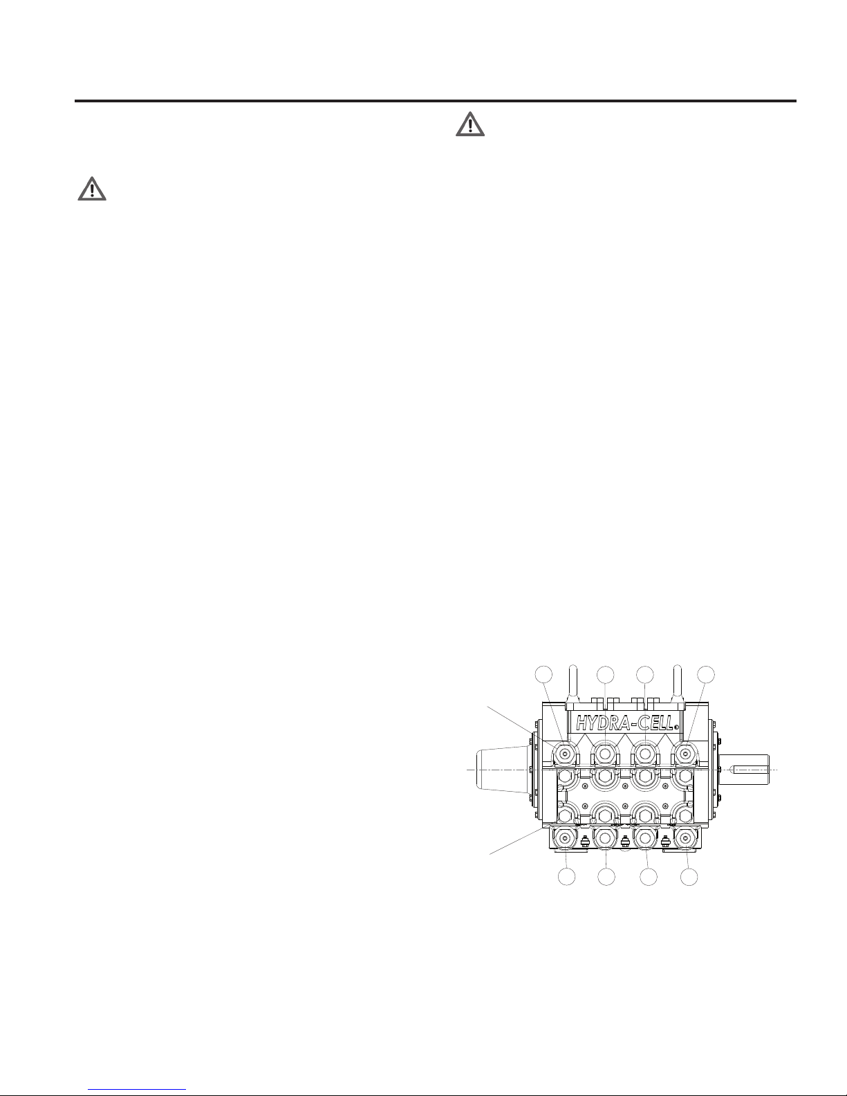
c. Thread on eight hex nuts (26) and hand tighten.
d. Tighten hex nuts in torque sequence shown below to 450
ft-lbs (610 N-m).
f. Tighten bolts in torque sequence shown below to
300 ft-lbs (407 N-m).
g. Fill pump with oil to cover marks on dipstick. Approximately
18 qts (17 liters) with at back cover or 20.5 US quarts (19.4
liters) with oil monitor back cover.
h. Follow instructions in Before Initial Start-Up and Initial
Start-Up Section to start pump.
Eight hex nuts (26)
6
2
4
8
Diaphragm Assembly
a. See Diaphragm Parts and Bias Rod Views. Install diaphragm
ring (75).
b. Install screw (74) to use as handle. Extract bias rod to expose
machined cross hole. Insert 1/8 inch (3 mm) hex wrench in
cross hole to restrain bias rod.
c. Remove and reinstall screw (74), o-ring (85), and follower (84)
to attach diaphragm clamp (82) and diaphragm (73). Use
Loctite 242 and torque to 60 in-lbs (7 N-m). Remove hex
wrench.
d. Seat diaphragm edge with ngers. Make sure diaphragm
bead is fully seated into the square groove of diaphragm
plate (52).
e. Repeat steps a. through d. for three diaphragms.
13
Eight bolts (101)
7
1
Torque sequence:
- Snug eight hex nuts (26) in order indicated,
then torque to 450 ft-lbs (610 N-m) in order
indicated.
- Repeat same snug and torque sequence for
corresponding bolts (101) to 300 ft-lbs (407 N-m).
W0539B
3
5
177- 9 9 8 D
Page 14

T100 High - Power End Service
Power End Disassembly
WA R N I N G: Crankc a s e (2) an d as s e m b l e d pa r ts we i g h
over 400 pounds (181 kg) and are a two man lift. Use
care in handling to prevent personal injury or damage
to equipment.
Float Switch Back Cover Disassembly
Note: The numbers in parentheses are the Reference
Numbers sh o w n in the Po w e r End Pa r ts View in th i s se c t i o n
of the manual and in the Parts Section of the manual.
a. Disconnect oat switch (48).
b. Remove oat switch adapter (47) with oat switch and
O-ring (46) from back cover (12).
c. Remove oat switch from oat switch adapter.
d. Remove twelve screws (16) from crankcase (2).
e. Remove back cover and bae (13).
f. Remove eight screws (45) from assembled frame (44)
and back cover.
g. Disassemble frame, gasket (43), sight glass (42),
and thick gasket (41).
Crankcase Disassembly
a. Remove Fluid End and Hydraulic plate as outlined in two
preceding sections.
b. See Power End Parts Illustration. Remove drain plug (40),
cap with o-ring (25), dipstick (32), and crankshaft key (31)
and drain lubricating uid into a suitable container.
c. Remove 12 cap screws (16) and remove back cover (12)
and back cover bae (13).
Connecting Rod Removal
Note: Each of three Connecting rod assemblies (3*)
consists of: connecting rod, connecting rod end cap,
sleeve, and two bolts.
a. Remove connecting rod assembly bolts (3*) and remove
connecting rod end cap (3*) with split shell bearing. Make
sure numbers on connecting rod and end cap are 'top-up'
in the assembly and match.
Note: Make sure to note 'top-up' orientation of numbers
on connecting rod and end cap when removing. These
are matched parts and must be stored together as one
assembly and not mixed with any other connecting rod
assemblies or parts.
b. Set aside connecting rod assembly bolts, end cap, and one
half split shell bearing (8) for use in reassembly.
c. Remove connecting rod assembly from crankshaft by
reaching into rear of crankcase (2) around crankshaft (1).
Push connecting rod assembly away from journal on the
crankshaft. Move as far forward as possible.
d. Repeat removal for three sets.
Crankshaft Removal
a. Remove six cap screws (16) from one side of pump attaching
seal and bearing assembly (assembled items 6, 7, 9, 11, 15,
17, and 18) to the crankcase (2).
b. Carefully remove crankshaft (1) with seal and bearing
assembly from crankcase.
c. Remove seal and bearing assembly from end of crankshaft.
d. Remove six screws (15) and remaining seal and bearing
assembly from crankcase.
Seal and Bearing Disassembly
a. Separate seal and bearing assemblies by removing six cap
screws (15).
b. Remove O-ring (17) from bearing cover (6). Remove roller
bearing (7) from bearing cover.
c. Remove O-ring (18) from seal cover (9). Remove two
crankshaft seals (11) from seal cover.
d. Disassemble two sets.
Connecting Rod Disassembly
Note: Make sure to note 'top-up' orientation of numbers
on connecting rod and end cap when storing. These are
matche d pa r ts and mu s t no t be mixed with pa r ts from other
connecting rod assemblies.
a. Pull out connecting rod/plunger assembly and remove from
crankcase.
b. Remove remaining one half of split shell bearing (8) from
connecting rod (3*). Match with shell bearing already
removed in Connecting Rod Removal.
c. Retrieve bolts (3*), and end cap (3*) from previous step in
Connecting Rod Removal. Be careful not to mix with parts
from other connecting rod assemblies.
d. Loosely assemble two bolts, and connecting rod end cap
with connecting rod assembly and set aside. Note proper
orientation of numbers on connecting rod and end cap.
e. Remove setscrew (23) to unlock wrist pin (5). Remove wrist
pin, assembled plunger and slider from connecting rod.
Note alignment marks on wrist pin and alignment mark on
crosshead (4).
f. Disassemble and remove three sets.
Plunger Disassembly
a. Remove shoulder screw (29) from plunger assembly to
remove plunger (53), spherical washer (27), slider (4), and
belleville spring (28).
b. Disassemble three sets as in step a.
c. Clean crankcase for later reassembly.
14
177- 9 9 8 D
Page 15

T100 High - Power End Service (Cont’d)
Power End Assembly
WAR N I N G : Crankc ase (2) and as s e m b l e d pa r ts we i g h
over 400 pounds (181 kg) and are a two man lift. Use
care in handling to prevent personal injury or damage
to equipment.
Plunger Assembly
Note: The numbers in parentheses are the Reference
Numbers shown in the Parts Section of the manual.
a. See Power End Parts Illustration. Start with crankcase (2)
clean and ready to assemble.
b. Assemble plunger (53), spherical washer (27), slider (4),
belleville spring (28), with shoulder screw (29). Use Loctite 242
and torque to 50 ft-lbs (68 N-m).
Note: One concave side of spherical washer assy (27) mates
with plunger (53) and the other convex side of spherical
washer assy mates with slider (4).
c. Assemble three sets.
Connecting Rod Assembly
Note: Each of three Connecting rod assemblies (3*)
consists of: connecting rod, connecting rod end cap,
sleeve, and two bolts.
a. Attach assembled plunger and slider to connecting rod (3*)
using wrist pin (5). Align marks on wrist pin with marks on
slider (4). Lock wrist pin in place with setscrew (23). Use
Loctite 271 and torque to 60 in-lbs (7 N-m).
Note: Make sure to note 'top-up' orientation of numbers
on connecting rod and end cap when taking apart. These
are matched parts and must not be mixed with parts from
other connecting rod assemblies.
b. Remove two bolts (3*) and connecting rod end cap (3*)
from connecting rod assembly. Note orientation numbers
on connecting rod and end cap.
c. Set aside bolts and end cap for later installation. Do not mix
with parts from other connecting rod assemblies.
d. Install one half of split shell bearing (8) on connecting rod.
Remaining one half of split shell bearing will be installed later.
e. Insert connecting rod/plunger assembly into crankcase and
push all the way forward. Ensure numbers are "top-up."
f. Assemble and install three sets.
Seal and Bearing Assembly
a. Press two crankshaft seals (11) into seal cover (9). Install
O-ring (19) onto seal cover.
b. Install roller bearing (7) into bearing cover (6). Install O-ring
(18) onto bearing cover.
c. Bolt seal and bearing assemblies together using six cap
screws (15).
d. Assemble two sets.
Crankshaft Installation
a. Install one seal and bearing assembly to either side of
crankcase (2) using six screws (15). Crankshaft (1) will be
installed on opposite side.
b. Place remaining seal and bearing assembly on following end
of crankshaft.
Note: No shimming of crankshaft is necessary. End play
of crankshaft should be between 0.010 in. minimum to
0.200 in. maximum when installed.
c. Insert crankshaft with seal and bearing assembly into
crankcase and insert into installed seal and bearing
assembly on opposite end of crankcase. Align ange of seal
and bearing assembly with ange on crankcase.
d. Bolt ange of seal and bearing assembly to crankcase with
six cap screws (15). Torque to 12 ft-lbs (16 N-m).
Connecting Rod Installation
Note: Each of three Connecting rod assemblies (3*)
consists of: connecting rod, connecting rod end cap,
sleeve, and two bolts.
a. Attach connecting rod assembly to crankshaft (1) by reaching
into rear of crankcase around crankshaft and pulling
connecting rod assembly until it reaches its journal on the
crankshaft.
Note: Make sure to note 'top-up' orientation of numbers
on connecting rod and end cap when installing. These are
matched pa rt s and must not be ta k e n fro m other connect i n g
rod assemblies.
b. Retrieve connecting rod assembly bolts, end cap, and
remaining split shell bearing (8) set aside in previous steps.
c. Reinstall connecting rod end cap with remaining split shell
bearing using connecting rod assembly bolts. Make sure
numbers on connecting rod and end cap are 'top-up' in the
assembly and match. Torque two bolts to 100 ft-lbs (136 N-m).
d. Repeat installation for three sets.
Crankcase Assembly
Note: fo r torque va l u e s re f e r to the table followin g th e Pa r t s
List Section.
a. Inst all back cove r (12) and bac k cover ba e (13) using 12
cap screws (16).
b. Install crankshaft cover (10) on crankshaft end not used
with six cap screws used to attach seal and bearing
assembly.
c. If removed, reinstall four studs (20), with four set screws (21),
four studs (19), and two eyebolts (14).
d. Install plug (40), cap with o-ring (25), dipstick (32), and
crankshaft key (31) and add lubricating uid.
Float Switch Back Cover Assembly
a. Align and assemble frame (44), gasket (43), sight glass (42),
and thick gasket (41).
15
177- 9 9 8 D
Page 16

T100 Series High Pressure - Troubleshooting
Float Switch Back Cover Assembly (Cont'd)
b. Install eight screws (45) alternately through assembled
frame into back cover (12) until snug.
c. Assemble bae (13) and back cover.
d. Attach bae and back cover to crankcase (2) with twelve
screws (16)
e. Assemble oat switch (48) to oat switch adapter (47)
nger tight plus one half turn.
f. Assemble oat switch adapter with oat switch and O-ring (46)
into back cover until seated.
g. Reconnect oat switch.
T100 Low Troubleshooting
Cavitation
• Inadequate uid supply because:
— Inlet line collapsed or clogged
— Clogged line strainer
— Inlet line too small or too long
— Air leak in inlet line
— Worn or damaged inlet hose
— Too many valves and elbows in inlet line
• Fluid too hot for inlet suction piping system
• Air entrained in uid piping system
• Aeration and turbulence in supply tank
• Inlet vacuum too high (refer to “Inlet Calculations” paragraph)
Symptoms of Cavitation
• Excessive pump valve noise
• Premature failure of spring or retainer
• Volume or pressure drop
• Rough-running pump
• Premature failure
Drop in Volume or Pressure
A drop in volume or pressure can be caused by one or more
of the following:
• Air leak in suction piping
• Clogged suction line or suction strainer
• Suction line inlet above uid level in tank
• Inadequate uid supply
• Pump not operating at proper RPM
• Relief valve bypassing uid
• Worn pump valve parts
• Foreign material in inlet or outlet valves
• Loss of oil prime in cells because of low oil level
• Ruptured diaphragm
• Cavitation
• Warped manifold from overpressurized system
• O-rings forced out of their grooves from overpressurization
• Air leak in suction line strainer or gasket
• Cracked suction hose
• Empty supply tank
• Excessive aeration and turbulence in supply tank
• Worn and slipping drive belt(s)
• Worn spray nozzle(s)
• Cracked cylinder
Pump Runs Rough
• Worn pump valves
• Air lock in outlet system
• Oil level low
• Wrong viscosity of oil for cold operating temperatures
(change to lighter viscosity)
• Cavitation
• Air in suction line
• Restriction in inlet/suction line
• Hydraulic cells not primed after changing diaphragm
• Foreign material in inlet or outlet valve
• Damaged diaphragm
• Fatigued or broken valve spring
Premature Failure of Diaphragm
• Frozen pump
• Puncture by a foreign object
• Elastomer incompatible with uid being pumped
• Pump running too fast
• Excess pressure
• Cavitation
• Aeration or turbulence in supply tank
Valve Wear
• Normal wear from high-speed operation
• Cavitation
• Abrasives in the uid
• Valve incompatible with corrosives in the uid
• Pump running too fast
Loss of Oil
• External seepage
• Rupture of diaphragm
• Frozen pump
• Worn shaft seal
• Oil drain plug or ll cap loose
• Valve plate and manifold bolts loose
Premature Failure of Valve
Spring or Retainer
• Cavitation
• Foreign object in the pump
• Pump running too fast
• Spring/retainer material incompatible with uid being pumped
• Excessive inlet pressure
16
177- 9 9 8 D
Page 17
T100 Series - Oil Level Monitor
Low
Closed
Open
Normal
Closed
Closed
Open
Closed
Low
Open
Open
Normal
Closed
Open
High
High
Closed
Open
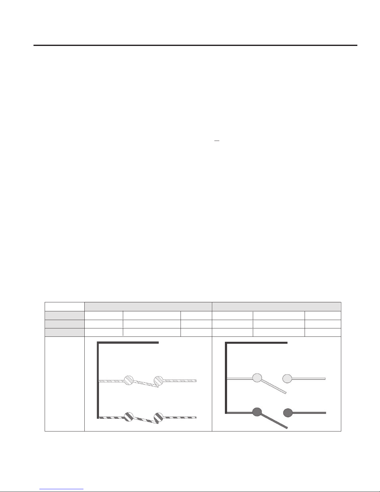
Oil Level Monitor Float Switch
Conditions and Wiring Diagram
CAUTION: The oat switch will only operate with crankshaft
rotation in the direction indicated on the pump casting.
Note: The numbers in parentheses are the Reference
Numbers shown in the Parts Section of the manual.
Note: The oat switch (48) and adapter (47) can be removed
from the back cover without draining the pump’s oil. See
the Installation and Maintenance sections of the manual
for oat switch set-up and use.
The oat switch (48) monitors the pump's oil level. The switch
is used to trigger an alarm or pump shutdown when a high or
low oil level is sensed in the pump's crankcase.
The T100 Low Pressure Pump uses one of two oat switch (48)
congurations. The switch used can be identied by its wire lead
colors and part number.
The wiring diagram below shows the operating conditions and
wiring colors for each type of switch assembly.
1. Normally-Closed (NC) Switch.
The Normally-Closed Float Switch, 177-453-02 contains two
normally-closed (NC) reed switches; one for high oil level, and
one for low oil level. The (NC) oat switch has solid Black,
striped Yellow/White, and striped Red/White wire leads.
2. Normally-Open (NO) Switch.
The Normally-Open Float Switch, 177-453-03 contains two
normally-open (NO) reed switches; one for high oil level, and
one for low oil level. The (NO) oat switch has solid Black, solid
Yellow, and solid Red wire leads.
Note: The oil level should always be visible between the
high and low oil marks viewed on sight glass (42). If the
oil level reaches the high or low mark, the oat switch will
be activated.
Electrical Specications
The following are the oat switch electrical specications:
1. For 177-453-02 Normally Open (NO) oat switch:
two single-pole, double-throw (SPDT) reed switches
rated at 150 VDC/VAC, 1 Amp, 20 Watts (maximum).
or
For 177-453-03 Normally Closed (NC) oat switch:
two single-pole, single-throw (SPST) reed switches
rated at 300 VDC/VAC, 0.5 Amp AC/0.7 Amp DC, 50
Watts (maximum).
2. Sum total of current for both switches not to exceed:
1 Amp
3. Resistive load only
4. Magnetic oat actuation
5. Electrical conduit connection at top of switch adapter:
1/2-14 NP T
6. UL File No. E203716 with Area Classication UL 508.
7. Not rated for NEC/CEC hazardous locations. Consult factory for explosive environments.
Additional Measurement Port
There is a port with plug (49) on the lower left side of the back
cover. This port may be used for an additional measurement
device.
Normally-Closed (NC) Switch, 177-453-02 Normally-Open (NO) Switch, 177-453-03
Oil Level
High Switch
Low Switch
Switch
conditions
shown for
normal
pump
operation
with float in
the middle
of the sight
glass.
Black (Common)
Yellow/White (High Oil Level)
Red/White (Low Oil Level)
Oil Level Monitor Float Switch Conditions and Wiring Diagram
17
Black (Common)
Yellow (High Oil Level)
Red (Low Oil Level)
W0624
177- 9 9 8 D
Page 18
W0533B
26
101
91
89
90
97
See Detail A
92
See Detail A
100
14
98
97
96
94
95
93
99
88
Inlet Valve
Outlet Valve
Detail A
102
103
104
105
106
107
Metalic
107
108
103
103
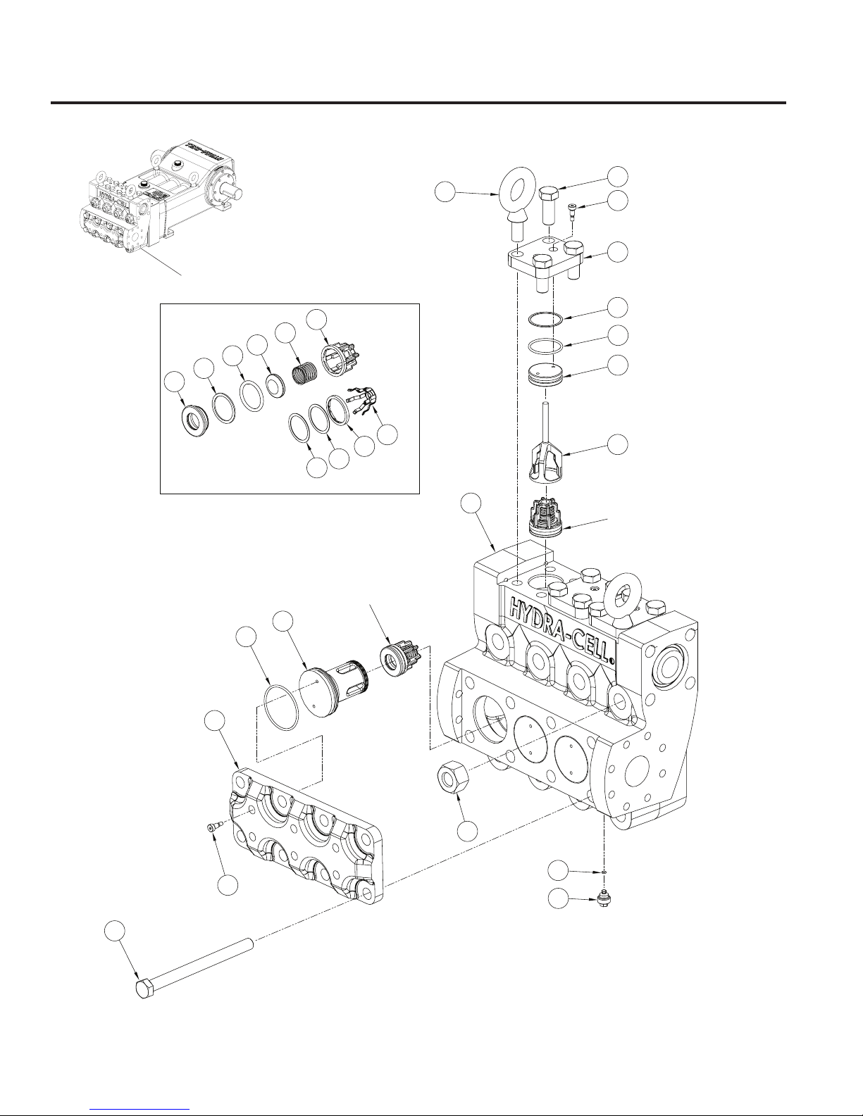
T100 Series High - Fluid End Parts
W0542B
Fluid End
18
Note: for torque values refer to the
Torque Specication Table.
177- 9 9 8 D
Page 19

T100 Series High - Fluid End Parts (Cont’d)
Ref. Quantity/
No. Part Number Description Pump
14 177-059 Eyebolt, M20 .......................................2
26 177-152 Nut, Hex, M27 .....................................8
88 177-210-04 Manifold, 316L SST .............................1
177-210-11 Manifold, NAB .....................................1
89 177-207-01 Plug, Inlet support, Austenitic SST .....3
90 177-227-01 O-ring, Buna-N ....................................3
177-227-02 O-ring, FKM ........................................3
91 177-121-02 Plate, Retainer, inlet ............................1
92 177-146-05 Retainer, Outlet, anged, Austenitic....3
177-146-20 Retainer, Outlet, 316 SST ...................3
93 177-148-01 Plug, Valve Port, outlet, SST ...............3
94 177-225- 01 Ring, Backup, Buna-N.........................3
177-225-02 Ring, Backup, FKM .............................3
95 177-226-01 O-ring, Buna-N ....................................3
177-226-02 O-ring, FKM ........................................3
96 177-110 Plate, Retainer, discharge cv .............3
97 177-052 Screw, Shoulder, M8, 12 mm ............12
98 177-044 Screw, Cap, hex-hd, M20, 50 mm. ....10
99 177-014-01 Plug, Drain, 316 SST ...........................3
100 D10-047-2110 O-ring, Buna-N ....................................3
D10-047-2111 O-ring, FKM ........................................3
101 177-116 Screw, Cap, hex-hd, M20, 250 mm ....8
102 177-202-01 Valve Seat, 17-4 SST, HT....................6
177-202-02 Valve Seat, Hastelloy C .......................6
177-202-05 Valve Seat, Nitronic .............................6
103 177-254-03 Ring, Back-up, PVDF ................ 6 or 12
177-254-04 Ring, Back-up ............................ 6 or 12
104 177-253-01 O-ring, Buna-N ....................................6
177-253-02 O-ring, FKM ........................................6
105 177-208-01 Valve, 17-4 SST, HT ............................6
177-208-02 Valve, Hastelloy C ...............................6
177-208-05 Valve, Nitronic ......................................6
106 177-209-01 Spring, Eligiloy ....................................6
177-209- 02 Spring, Hastelloy .................................6
107 177-206 -01 Retainer, Valve spring, Polypropylene ...6
177-206-02 Retainer, Valve spring, PVDF ...............6
177-206-04 Retainer, Valve spring, 17-7 SST ...........6
177-206-05 Retainer, Valve spring, 316 SST ............6
177-206-06 Retainer, Valve spring, Hastelloy C22 ...6
108 177-411-01 Ring, Lock, Austenitic SST..................6
177-411-02 Ring, Lock, Hastelloy ..........................6
19
177- 9 9 8 D
Page 20
69
66
54
59
53
58
72
57
65
56
55
24
52
W0534E
74
73
82
75
80
84
76
85
83
81
87
86
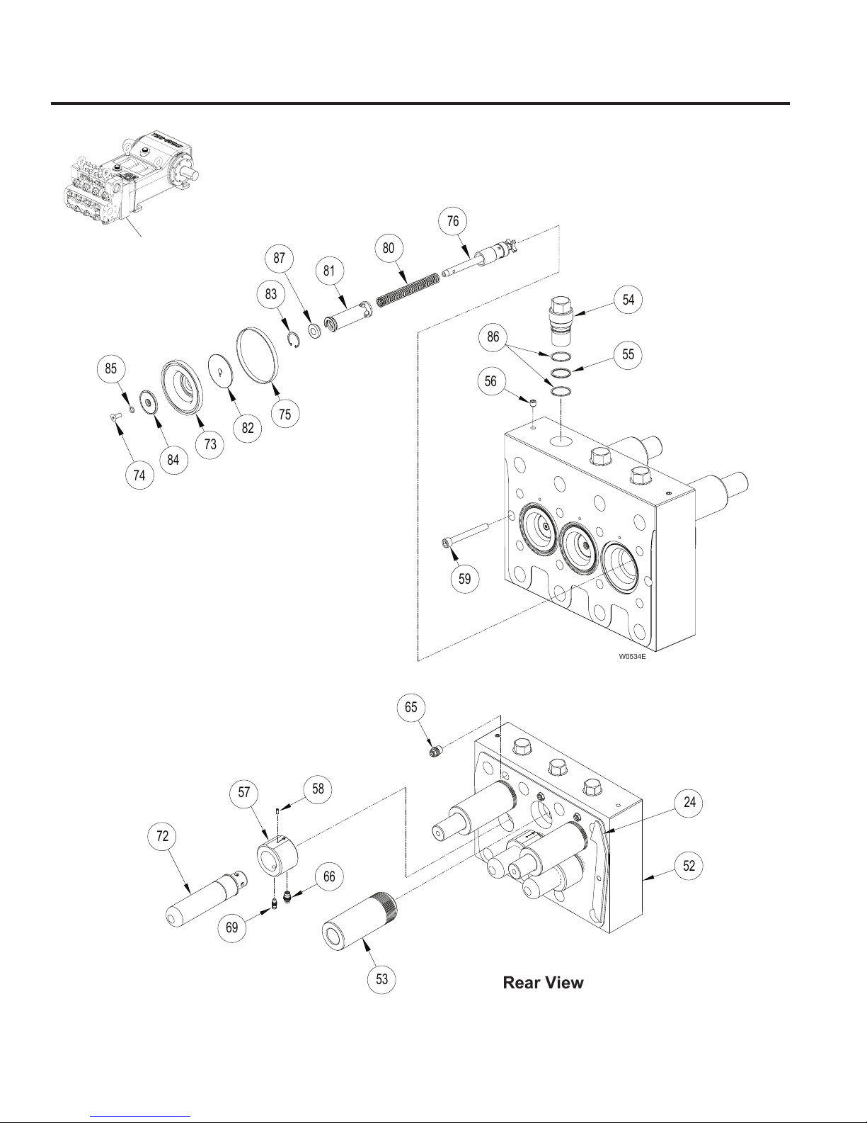
T100 Series High - Hydraulic Section Parts
Rear View
W0542B
Hydraulic Section
Note: for torque values refer to the
Torque Specication Table.
20
177- 9 9 8 D
Page 21

T100 High - Hydraulic Section Parts (Cont’d)
Ref. Quantity/
No. Part Number Description Pump
24 177-013 Gasket, Diaphragm plate ....................1
52 177-201-02 Plate, Diaphragm, T100 High .............1
53 177-229 Cylinder, S ...........................................3
54 177-231 Plug, Diaphragm plate .........................3
55 C22-016-2110 O-ring, Buna-N ....................................3
56 177-117 Setscrew, M10, 10 mm ........................2
57 177-235 Ring, Valve ..........................................3
58 177-237 Spring, Plunger ...................................3
59 G10-024-2010 Screw, Cap, soc-hd, M10, 90 mm .......2
65 177-906 Cartridge, Air Bleed valve ...................3
66 177-904 Cartridge, Underll valve ....................3
69 177-905 Cartridge, Overll valve ......................3
72 177-234 Tube, Bias spring.................................3
73 177-266-01 Diaphragm, Buna-N ............................3
177-266-02 Diaphragm, FKM .................................3
74 177-176-01 Screw, Flat-hd,
75 177-238 Ring, Diaphragm, back-up ....................3
76 177-916 Diaphragm Rod Assembly ..................3
80 177-223 Spring, Bias .........................................3
81 177-258 Diaphragm Stop ..................................3
82 177-263 Clamp, Diaphragm ..............................3
83 177-249 Ring, Retaining, internal ......................3
84 177-267-01 Follower, Austenitic SST .....................3
85 100-217-01 O-ring, Buna-N ...................................3
100-217-02 O-ring, FKM .......................................3
86 177-272 Ring, Back-up, PTFE...........................6
87 177-265 Spacer, Bias spring .............................3
M6 x 1.0 x 16 mm, Aus ..3
21
177- 9 9 8 D
Page 22
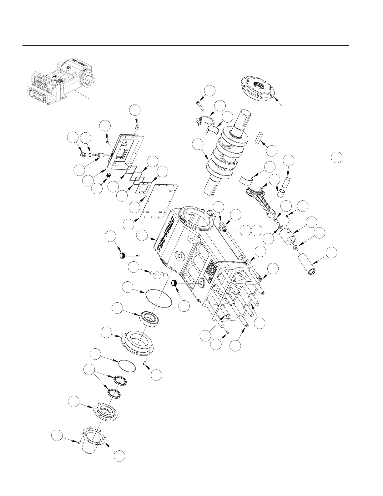
T100 Series High - Power End Parts
W0542B
Power End
47
46
48
12
49
16
32
41
43
13
50
45
14
3*
3*
8
Items 6, 7, 9, 11, 15, 17,
and 18 assembled
1
31
42
5
8
3*
44
3*
* Note: item consists of: connecting rod,
connecting rod end cap, sleeve, and two bolts.
29
W0535B
40
23
37
4
38
2
39
28
36
27
51
35
15
17
7
25
24
6
19
21
20
18
11
15
9
Note: for torque values refer to the
Torque Specication Table.
10
22
177- 9 9 8 D
Page 23

T100 Series High - Power End Parts (Cont’d)
Ref. Quantity/
No. Part Number Description Pump
1 177-002-06 Crankshaft, Forged .............................1
2 177-001-02 Crankcase ..........................................1
3 177-003-02 Connecting Rod Assembly ..................3
4 177-005 Slider ...................................................3
5 177-032 Pin, Wrist .............................................3
6 177-021 Cover, Bearing ....................................2
7 177-027 Bearing, Roller, spherical ....................2
8 177-041 Bearing, Split shell (pair) .....................3
9 177-034 Cover, Seal ..........................................2
10 177-035 Cover, Crankshaft ...............................1
11 177-028 Seal, Crankshaft ..................................4
12 177-022 Cover, Back (no Oil Monitor) ...............1
177-450-02 Cover, Float switch (Oil Monitor) .........1
13 177-026 Gasket, Back cover (no Oil Monitor) ...1
177-451 Bae, Float switch (Oil Monitor) .........1
14 177-059 Eyebolt, M20 .......................................2
15 177-048 Screw, Cap, hex-hd, M8, 25 mm .......24
16 177-043 Screw, Cap, hex-hd, M8, 15 mm .......12
17 H25-037-2110 O-ring, Buna-N ....................................2
18 D10-109-2110 O-ring, Buna-N ....................................2
19 177-150 Stud, 27 mm x 300 mm .........................4
20 177-151 Stud, 27 mm x 300 mm, c-bore 12 mm ..4
21 177-118 Setscrew, M12, 15 mm ........................4
23 G10-082-2010 Setscrew, M6, 10 mm ..........................3
24 177-013 Gasket, Diaphragm plate ................ Ref
25 D03-039-1030 Cap, Oil ll (with o-ring) .......................1
27 177-031 Washer, Spherical ...............................3
28 177-030 Spring, Belleville ..................................3
29 177-047 Screw, Shoulder, M16, 30 mm ............3
31 177-036 Key, Crankshaft ...................................1
Ref. Quantity/
No. Part Number Description Pump
32 177-912 Dipstick ................................................1
35 209-701 Fitting, 5/8 Tube ..................................1
36 209-711 Tube, 5/8 x 22 1/2 x .049 .....................1
37 209-710 Fitting, Flareless tube ..........................1
38 209-712 Tube, 1 7/8 X .049 ...............................1
39 209-702 Fitting, 90⁰ Elbow ................................1
40 189-313 Plug, 1/2 in. NPT .................................1
41 177-456 Gasket, Sight glass, thick ....................1
42 177-454 Glass, Sight .........................................1
43 177-452 Gasket, Sight glass .............................1
44 177-455 Frame, Sight glass ..............................1
45 189-565 Screw, 10-24 pan-hd ...........................8
46 D03-075-2110 O-Ring, Buna-N ..................................1
47 177-457 Adapter, Float switch ...........................1
48 177-453-02 Switch, Float, normally closed ............1
177-453-03 Switch, Float, normally open ...............1
49 189-311 Plug, 3/4 NPT, SST .............................1
50 177-459 Plug, 1/2-14 NPT, SST ........................1
51 177-203 Plunger, S ............................................3
23
177- 9 9 8 D
Page 24
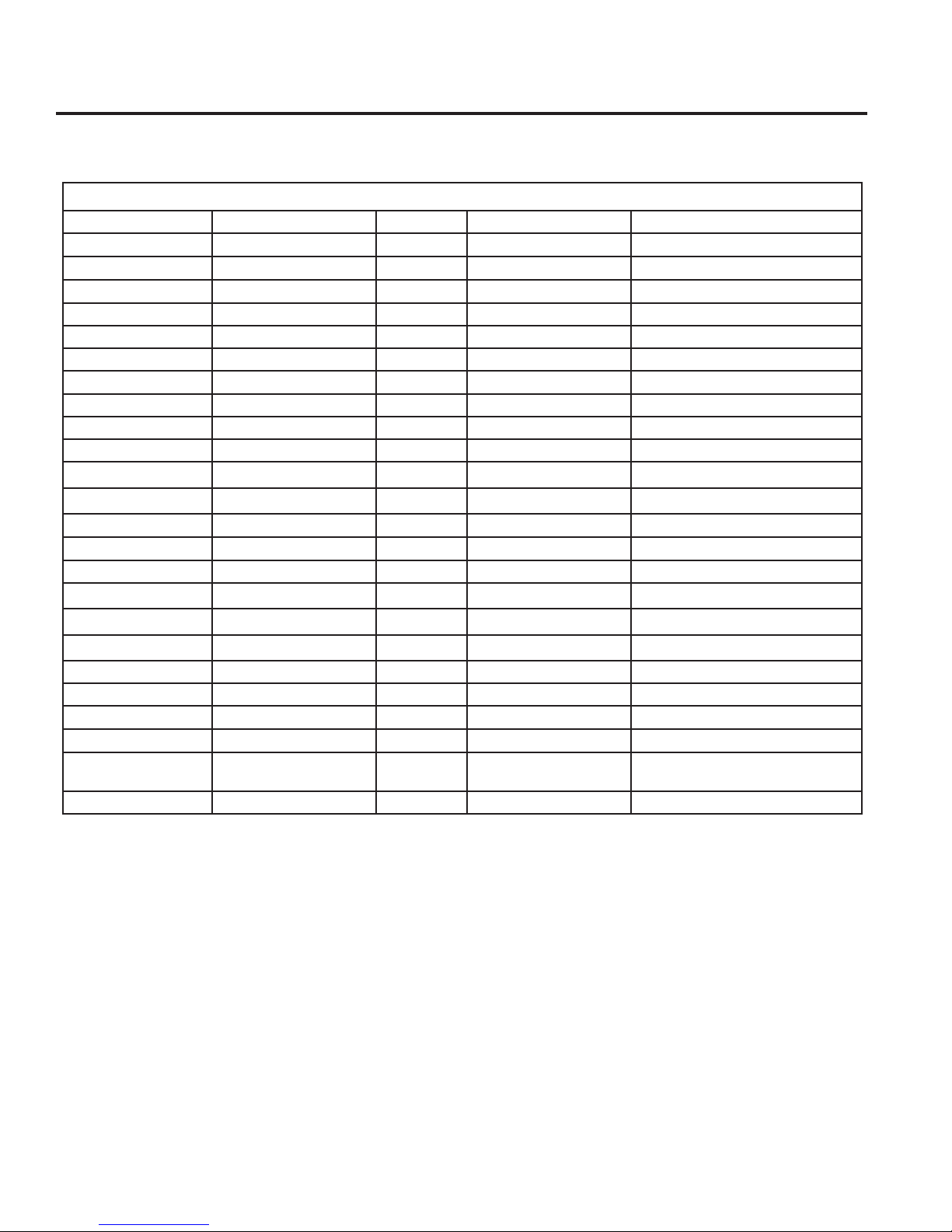
T100 Series High - Torque Specications
Torque Specications for the T100S
Torque Specication Table
Reference Number Torque Specication (N-m) Loctite No. Part Number Description
3 100 ft-lbs (136) 177-003-02 Bolts, Connecting Rod Assembly
14 300 ft-lbs (407) 177- 059 Eyebolt, M20
15 12 ft-lbs (16) 242 177- 048 Screw, Cap, hex-hd, M8, 25 mm
16 12 ft-lbs (16) 242 177- 0 4 3 Screw, Cap, hex-hd, M8, 15 mm
19 200 ft-lbs (271) 242 177-150 Stud, 27 mm x 300 mm
20 200 ft-lbs (271) 242 17 7-151 Stud, 27 mm x 300 mm, c-bore 12 mm
23 60 in-lbs (7) 271 G10- 082-2010 Screw, Soc-hd, M6, 10 mm
26 450 ft-lbs (610) 177-152 Nut, Hex, M27
29 50 ft-lbs (68) 242 177-047 Screw, Shoulder, M16, 30 mm
45 15 in-lbs (1.7) 271 189-565 Screw, Pan-hd, 10-24
49
50
53 450 f t-lbs (610) 242 177-2 2 9 Cylind er, S
54 300 ft-lbs (407) 177-2 31 Plug, Diaphragm plate
59 50 ft-lbs (68) G10- 024-2010 Screw, Cap, soc-hd, M10, 90 mm
65 75 ft-lbs (101) 177- 906 Cartridge, Air Bleed valve
66 30 ft-lbs (41) 177- 9 0 4 Cartridge, Underll valve
69 105 in-lbs (12) 177- 9 0 5 Cartridge, Overll valve
74 60 in-lbs (7) 242 177-176 Sc rew, Flat-hd, M6 x 1.0 x 16 mm
97 75 in-lbs (8) 242 177-052 Screw, Shoulder, M8, 12 mm
98 300 ft-lbs (407) 177- 0 4 4 Screw, Cap, hex-hd, M20, 50 mm
99 40 ft-lbs (54) ** 177-014-01 Plug, Drain
100 * ** D10 - 047-2110
101 300 ft-lbs (407) 177-11 6 Screw, Cap, hex-hd, M20, 250 mm
♯
♯
* No torque requirement, Loctite only.
** Apply Loctite nickel anti-sieze lubricant to threads and chamfer of item 99, with coverage on item 100.
♯
Apply instant pressure pipe thread sealant.
18 9 - 311 Plug, 3/4 in. NPT, SST
177- 459 Plug, 1/2-14 NPT
O-ring, Buna-N
D10 - 0 47- 2 111
O-ring, FKM
24
177- 9 9 8 D
Page 25
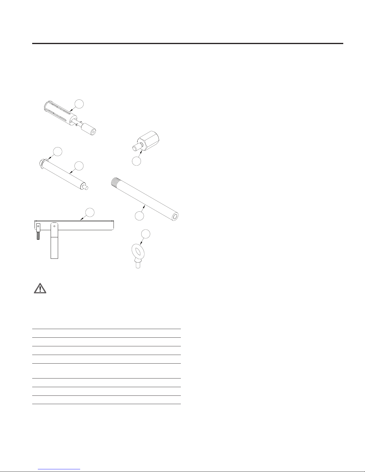
T100 Series High - Tool Kit and Pump Storage
T100 High Pressure Tool Kit
The T100 High Pressure Tool Kit (Part No. 177-807)
contains the tools illustrated below. These tools are used to
assist in the repair and maintenance of the T100S. See the
maintenance sections of this manual for specic application.
1
2
4
3
5
6
Pump Storage for T100 Low Pressure
CA UTION: If the pu m p is to be stored more than si x mo n t h s
take the following steps to protect against corrosion:
After Shut Down of the pump:
1. Drain all process uid from pump. Do not drain oil from the
pump.
CAUTION - Do not store the pump without oil in the
reservoir.
2. Flush the uid end of the pump with a corrosion inhibitor that
is compatible with the diaphragm material and process uid.
3. Coat camshaft or crankshaft with rust preventative; wrap
with wax-impregnated cloth and then with waterproof tape.
4. Plug the suction and discharge ports of the pump to protect
against dirt and moisture.
5. Store in a clean, dry place.
Prior to Start-up of the pump:
1. Drain and rell the hydraulic end of the pump with the
appropriate Hydra-Oil.
8
W0538A
WARNING: Item 8, M10 Diaphragm Plate Eyebolt is
used to lift Diaphragm Plate (52) only. Do not use to
lift entire pump. At t e m p t i n g to li f t en t i r e pu m p wi t h Eyebolt
(8) may cause personal injury or damage to equipment.
Ref. Quantity/
No. Tool Part No. Tool Description Kit
1 177-915 Inlet Check Valve Extractor ................1
2 177-392 Clip, E-style .........................................4
3 A03-124-1200 Check Valve Extractor Lever .............1
4 177-393 Stud Extender .....................................4
5 177-157 Thread Adapter, Check valve extractor
to slide hammer ..................................1
6 177-140 Outlet Check Valve Extractor, Flange ..1
7 A03-126-1500 Toolbox (not illustrated) .......................1
8 177-058 Diaphragm Plate Eyebolt, M10 ............2
25
177- 9 9 8 D
Page 26
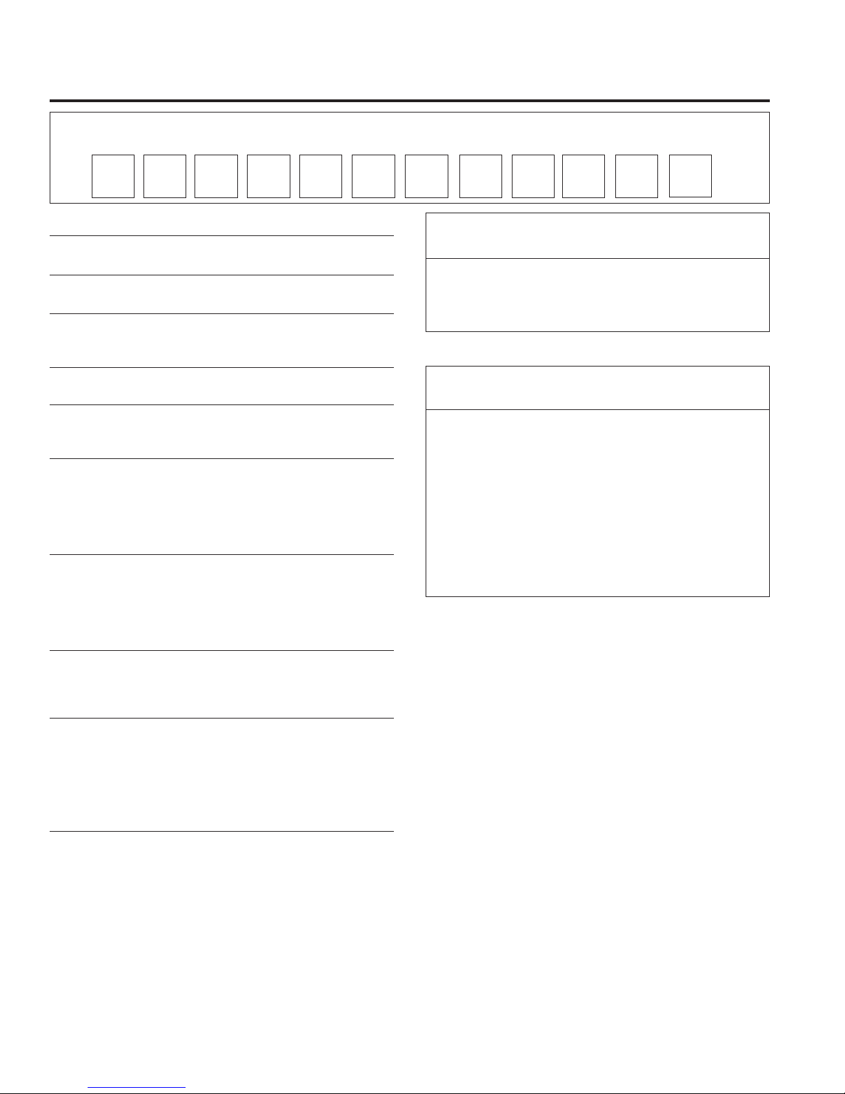
T100 High - Replacement Parts Kits
TO ORDER REPLACEMENT PARTS KIT: A Replacement Parts Kit contains 11 digits corresponding to customer-specied design options.
1
Order
Digit Code Description
1-4 Pump Conguration
T100 For all T100 Series Pumps
5 Performance
6 Kit Designator
D Diaphragm Kit
V Valve Kit
7 Pump Head Material
5 Metallic Pump Head Version
8 Diaphragm & O-ring Material
G FKM
T Buna-N
9 Valve Seat Material
D Tungsten Carbide*
H 17-4 PH Stainless Steel
N Nitronic 50
T Hastelloy C
X Not included in Diaphragm Kit
10 Valve Material
D Tungsten Carbide*
F 17-4 PH Stainless Steel
N Nitronic 50
T Hastelloy C
X Not included in Diaphragm Kit
11 Valve Springs
E Elgiloy
T Hastelloy C
X Not included in Diaphragm Kit
12 Valve Spring Retainers
H 17-7 Stainless Steel
M PVDF
P Polypropylene
S 316 SST
T Hastelloy C
X Not included in Diaphragm Kit
*Tungsten Carbide valve seat and disc are a matched set and must be
purchased together.
H High Pressure (T100S)
2
53
6 9 10
84 7
T100 High Pressure Kit D Contents
Part Number* * Description Quantity
177-260-__ Diaphragm 3
177- 238 Ring, Back-up 3
100-217- __ O-ring 3
T100 High Pressure Kit V Contents
Part Number* * Description Quantity
177-2 02- __ Valve Seat 6
177-2 5 4 - 03 Ring, Back-up, PVDF 6
177-2 53- _ _ O-ring 6
177-2 08- _ _ Valve Disc 6
177-2 0 9 - _ _ Spring 6
177-2 0 6 - _ _ Retainer, Valve spring 6
177-2 25 - _ _ Ring, Back-up 3
177-226-__ O-ring 3
177-2 27- _ _ O-ring 3
** Last four digits of part numbers with –_ _ _ refer to specic material of
construction.
11
12
26
177- 9 9 8 D
Page 27
T100 Series High Pressure - Warranty
Limited Warranty
Wanner Engineering, Inc. extends to the original purchaser
of equipment manufactured by it and bearing its name, a
limited one-year warranty from the date of purchase against
defects in material or workmanship, provided that the
equipment is installed and operated in accordance with the
recommendations and instructions of Wanner Engineering,
Inc. Wanner Engineering, Inc. will repair or replace, at its
option, defective parts without charge if such parts are
returned with transportation charges prepaid to Wanner
Engineering, Inc., 1204 Chestnut Avenue, Minneapolis,
Minnesota 55403.
This warranty does not cover:
1. The electric motors (if any), which are covered by
the separate warranties of the manufacturers of these
components.
2. Normal wear and/or damage caused by or related to
abrasion, corrosion, abuse, negligence, accident, faulty
installation or tampering in a manner which impairs normal
operation.
3. Transportation costs.
This limited warranty is exclusive, and is in lieu of any
other warranties (express or implied) including warranty
of merchantability or warranty of tness for a particular
purpose and of any non contractual liabilities including
product liabilities based on negligence or strict liability.
Every form of liability for direct, special, incidental or
consequential damages or loss is expressly excluded and
denied.
27
177- 9 9 8 D
Page 28
Wanner Engineering, Inc.
World Headquarters & Manufacturing
Wanner Engineering, Inc
1204 Chestnut Avenue,
Minneapolis, MN 55403 USA
Phone: 612-332-5681 ● Fax: 612-332-6937
Toll-Free Fax (USA): 800-332-6812
Email: [email protected]
www.Hydra-Cell.com
207 US Highway 281
Wichita Falls, TX 76310 USA
Phone: 940-322-7111
Toll-Free Fax: 800-234-1384
Email: [email protected]
www.Hydra-Cell.com
Latin American Ofce
São Paulo, Brazil
Phone: +55 (11) 4081-7098
Email: [email protected]
www.Hydra-Cell.com
Wanner International Ltd.
Wanner International Ltd
Hampshire - United Kingdom
Phone: +44 (0) 1252 816847
Email: [email protected]m
www.Hydra-Cell.eu
Wanner Pumps Ltd.
Wanner Pumps Ltd.
Kowloon - Hong Kong
Phone: +852 3428 6534
Email: [email protected]
www.WannerPumps.com
Shanghai - China
Phone: +86-21-6876 3700
Email: [email protected]
www.WannerPumps.com
© 2012 Wanner Engineering, Inc. Printed in USA
177-998D 3/2012, Revised 8/2017
 Loading...