

Hydra-Cell P400 Installation Service
T M
P400 Metering Pump
W0014A
Installation & Service
P400-991-2400B
1204 Chestnut Avenue, Minneapolis, MN 55403
TEL: (612) 332- 56 81 FA X: (612) 332-6937
TOLL-FREE FAX [US only]: (800) 332-6812
www.hydra-cell.com/metering
email: sales@wannereng.com
Non-Metallic Pump shown

P400 Contents
W0014A
Page
Component Identification
Specifications ..........................................................................2
Dimensions .............................................................................3
Installation ...............................................................................5
Maintenance ............................................................................7
Fluid End
Outlet
Service .................................................................................8
Parts List ............................................................................12
Hydraulic End Parts List .......................................................14
Reducer Parts List ................................................................16
Troubleshooting.....................................................................18
Replacement Parts Kits ........................................................19
Warranty ............................................................................... 20
Inlet
Pump Assembly
P400 Specifications
Steady State Accuracy ±1%
Linearity ±3%
Repeatability ±3%
Maximum Pressure
Metallic Head: 1000 psi (70 bar)
Non-Metallic Head: Polypropylene: 250 psi (17 bar)
Kynar: 350 psi (24 bar)
Maximum Inlet Pressure 250 psi (17 bar)
Maximum Temperature
Metallic Head: 250°F (121°C) – consult factory for
temperatures above 160°F (71°C)
Inlet Port 1 inch NPT or BSPT
Discharge Port 3/4 inch NPT or BSPT
Shaft Rotation Bi-directional
Oil Capacity† 1.1 US quart (1.05 liters)
Weight
Metallic Head: 62 lbs (28.1 kg)
Non-Metallic Head: 49 lbs (22.2 kg)
Metallic Head with Motor Adapter: 68 lbs (30.8 kg)
Non-Metallic Head with Motor Adapter: 55 lbs (25 kg)
Fluid End
Non-Metallic Head: 140°F (60°C)
Gallons Per Hour (GPH) Maximum Flow at Designated Pressure†
GPH All Pumps GPH Metallic Pump Heads Only
100 PSI (*) 250 PSI (*) 500 PSI (*) 1000 PSI (*)
5.45 (¼) 5.40 (¼) 5.35 (¼) 5.19 (¼) 18 100:1
6.97 (¼) 6.92 (¼) 6.86 (¼) 6.68 (¼)
9.51 (¼) 9.45 (¼) 9.38 (¼) 9.16 (¼)
11.54 (¼) 11.48 (¼) 11.40 (¼) 11.15 (¼)
14.59 (¼) 14.52 (¼) 14.43 (¼) 14.13 (¼)
19.66 (¼) 19.59 (¼) 19.47 (¼) 19.10 (¼)
23.72
(¼) 23.64 (¼) 23.51 (¼) 23.07 (½)
29.81
(¼) 29.72 (¼) 29.56 (¼) 29.04 (½)
39.96 (¼) 39.85 (¼) 39.65 (½) 38.97 (½)
60.27
(¼) 60.12 (¼) 59.83 (½) 58.84 (¾)
80.57 (¼) 80.38 (¼) 80.00 (¾) 78.71 (1)
121.2
(¼) 120.9 (½) 120.4 (1) 118.5 (1½)
161.8 (½) 161.4 (¾) 160.7 (1½) 158.2 (2)
(½) 242.5 (1) 241.4 (2) 237.7 (3)
243.0
*Required Motor HP
† Capacity data shown is for pumps with elastomeric diaphragms. Consult factory for
performance characteristics of pumps with PTFE diaphragms.
Pump
RPM
22.5
30 60:1
36 50:1
45 40:1
60 30:1
72 25:1
90 20:1
120
180 10:1
240
360 5:1
480 7.5:1
720
Oil Fill Cap ID Plate
Gear
Ratio
80:1
15:1
7.5:1
5:1
Motor
RPM
1800
3600
Reducer
Pump Assembly
Hydraulic End
2
P400-991-2400B
OUT
IN
WANNER
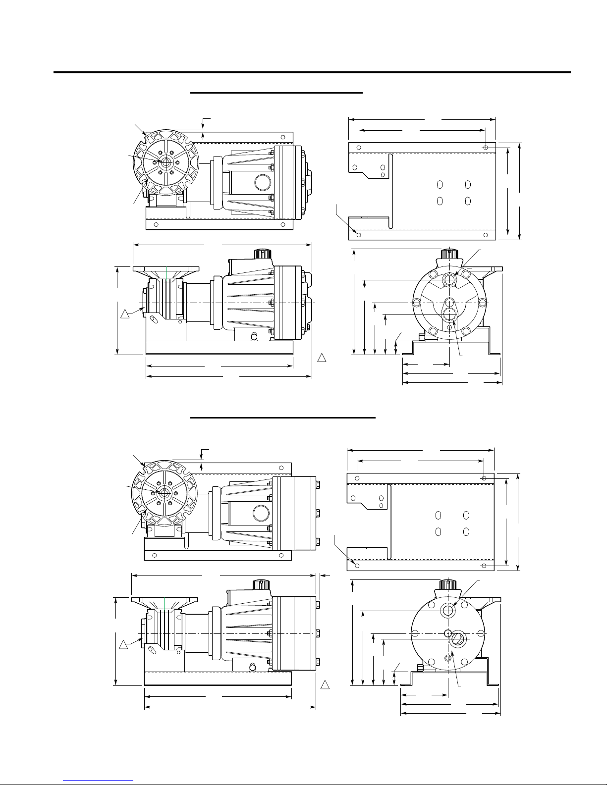
8.68
(220.5)
18.19
(462)
0.39
(9.9)
16.91
(429.5)
14.50
(368.3)
1" NPT or
1" BSPT
3/4" NPT or
3/4" BSPT
1
1
Note:
Worm Gear Reducer available
in the following ratios: 5:1, 7.5:1,
10:1, 15:1, 20:1, 25:1, 30:1, 40:1,
50:1, 60:1, 80:1, 100:1.
Ø6.50
(165.1)
NEMA 56C
Flange
Pilot
Ø4.500
(114.3)
Bolt Circle
Ø5.875
(149.2)
NEMA
56C
Ø0.625
(15.88)
Square
Key
0.187
(4.75)
0.24
(6.1)
4.65
(118.1)
9.64
(244.9)
9.87
(250.7)
10.34
(262.6)
Ø0.41
(10.4)
4X
7.38
(187.5)
5.13
(130.3)
4.57
(116.1)
1.37
(34.8)
8.63
(219.2)
9.63
(244.6)
14.50
(368.3)
12.50
(317.5)
W0018
P400 Dimensions
OUT
WANNER ENG.
IN
8.68
(220.5)
17.59
(446.8)
16.32
(414.5)
14.50
(368.3)
1" NPT or
1" BSPT
3/4" NPT or
3/4" BSPT
1
1
Note:
Worm Gear Reducer available
in the following ratios: 5:1, 7.5:1,
10:1, 15:1, 20:1, 25:1, 30:1, 40:1,
50:1, 60:1, 80:1, 100:1.
Ø6.50
(165.1)
NEMA 56C
Flange
Pilot
Ø4.500
(114.3)
Bolt Circle
Ø5.875
(149.2)
NEMA
56C
Ø0.625
(15.88)
Square
Key
0.187
(4.75)
0.24
(6.1)
4.65
(118.1)
9.64
(244.9)
9.87
(250.7)
10.34
(262.6)
Ø0.41
(10.4)
4X
7.38
(187.5)
5.13
(130.3)
4.01
(101.9)
1.37
(34.8)
8.63
(219.2)
9.63
(244.6)
14.50
(368.3)
12.50
(317.5)
W0017
P400 Models with Metallic Pumping Head
316 Stainless Steel
Cast Iron
Hastelloy® C
Inches (mm)
P400 Models with Non-Metallic Pump Head
Kynar
Polypropylene
3
P400-991-2400B
OUT
IN
WANNER
12.50
(317.5)
1.00
(25.4)
18.44
(468.4)
0.39
(9.9)
8.63
(219.2)
9.64
(244.9)
Ø0.41
(10.4)
4X
5.13
(130.3)
4.65
(118.1)
7.38
(187.4)
0.97
(24.6)
10.34
(262.6)
4.57
(116.1)
1.37
(34.8)
9.64
(244.9)
0.48
(12.2)
1" NPT or
1" BSPT
3/4" NPT or
3/4" BSPT
14.50
(368.3)
16.91
(429.5)
1
1
Worm Gear Reducer
available in the following
ratios - 5:1, 7.5:1
Note:
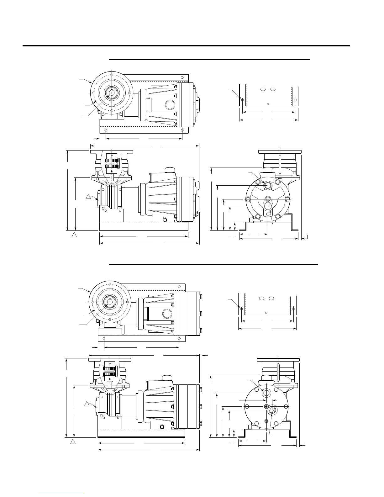
2. Weight = 55 lbs (25 kg) (no motor)
13.15
(334)
8.68
(220.5)
Ø7.00
(177.8)
NEMA 143/5TC Flange
Ø4.500 (114.3) Pilot
Ø5.875 (149.2) B.C.
NEMA 143/5TC
Ø0.875 (22.2)
0.187 (4.75) Square Key
W0314
P400 Dimensions
OUT
WANNER ENG.
IN
8.63
(219.2)
9.64
(244.9)
Ø0.41
(10.4)
4X
Ø7.00
(177.8)
NEMA 143/5TC Flange
Ø4.500 (114.3) Pilot
Ø5.875 (149.2) B.C.
NEMA 143/5TC
Ø0.875 (22.2)
0.187 (4.75) Square Key
12.50
(317.5)
17.84
(453.1)
1.00
(25.4)
14.50
(368.3)
16.32
(414.5)
1
1
Worm Gear Reducer
available in the following
ratios - 5:1, 7.5:1
Note:
2. Weight = 68 lbs (30.8 kg) (no motor)
13.15
(334)
8.68
(220.5)
5.13
(130.3)
4.65
(118.1)
7.38
(187.4)
10.34
(262.6)
4.01
(101.9)
1.37
(34.8)
9.64
(244.9)
0.48
(12.2)
1" NPT or
1" BSPT
3/4" NPT or
3/4" BSPT
W0306
P400 Models with Metallic Pumping Head and Motor Adapter
316 Stainless Steel
Cast Iron
Hastelloy® C
Inches (mm)
P400 Models with Non-Metallic Pump Head and Motor Adapter
Kynar
Polypropylene
4
P400-991-2400B
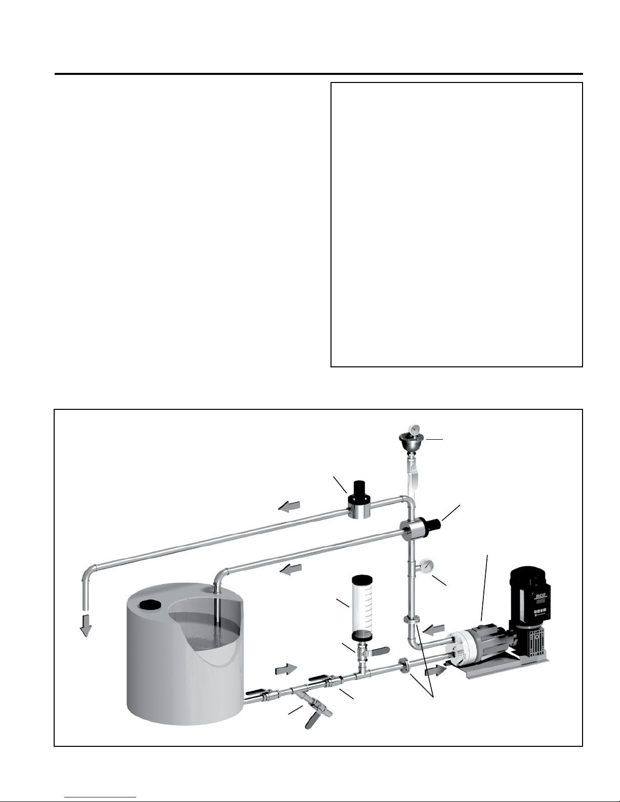
P400 Installation
P400
METERING PUMP
PULSATION
DAMPENER
(OPTIONAL)
CALIBRATION
CYLINDER
Y-STRAINER
ISOLATING VALVE
BALL VALVE
RELIEF
VALVE
FLANGES & MANIFOLDS
BACK PRESSURE
VALVE
(To process)
PRESSURE
GAUGE
W0326
Location
NOTE: The numbers in parentheses are Reference Numbers
located in the Parts List exploded views of this manual.
Locate the pump as close to the supply source as possible.
Install it in a lighted clean space where it will be easy to inspect
and maintain.
Motor and Controller
The P Series pump shaft can rotate in either direction, therefore
direction of motor shaft rotation is not critical.
Accessories
Consult installation drawing below for typical precision metering
fluid system components. Contact Wanner Engineering or the
distributor in your area for more details.
Important Precautions
Ad equ ate Fluid Supp ly. To avo id cavi tat ion and
premature pump failure, be sure that the pump will have
an adequate fluid supply and that the inlet line will not be
obstructed. See Inlet Piping on page 6.
Positive Displacement. This is a positive-displacement
pump. To avoid severe system damage if the discharge line
ever becomes blocked, install a relief valve downstream
from the pump. See Discharge Piping on page 6.
Safety Guards. Follow all codes and regulations regarding
installation and operation of the pumping system.
Shut-Off Valves. Never install shut-off valves between
the pump and discharge pressure regulator, or in the
regulator bypass line.
Consult the Factory for the following situations:
• Extreme temperature applications (above 160° F or
below 40° F)
• Pressure feeding of pumps
• Viscous or abrasive fluid applications
• Chemical compatibility problems
• Hot ambient temperatures (above 110° F)
5
P400-991-2400B

P400 Installation
Inlet Piping
Provide for permanent or temporary installation of a compound
pressure gauge to monitor the inlet pressure. To maintain
maximum flow, the pump inlet should be under flooded suction
conditions at all times. Do not supply more than one pump
from the same inlet line.
Supply Tank
Use a supply tank that is large enough to provide time for any
trapped air in the fluid to escape. The tank size should be at
least twice the maximum pump flow rate.
Install a separate inlet line from the supply tank to each
pump.
Place a cover over the supply tank, to prevent foreign objects
from falling into it.
Hose Sizing and Routing
To minimize acceleration head and frictional losses, size the
suction line at least one size larger than the pump inlet, and
keep the suction line as short and direct as possible.
Recommendations:
• Keep inlet lines less than 3 ft. (1 m) long
• Use at least 1-1/2” (38 mm) I.D. inlet hose
• Minimize fittings (elbows, valves, tees, etc.)
Inlet Piping (Pressure Feed)
Provide for permanent or temporary installation of a pressure
gauge to monitor the inlet pressure. Pressure at the pump inlet
should not exceed 250 psi (17 bar); if it could get higher, install a
pressure reducing valve. Do not supply more than one pump
from the same inlet line.
Note: System back pressure must exceed the pump inlet
pressure by at least 15 psi (1 bar) in order to prevent
flow thru.
Discharge Piping
Hose and Routing
Use the shortest, most-direct route for the discharge line.
Select pipe or hose with a working pressure rating of at least
1.5 times the maximum system pressure. EXAMPLE: Select a
1500 psi (103 bar) W.P.-rated hose for systems to be operated
at 1000 psi (69 bar) gauge pressure.
Support the pump and piping independently.
Pressure Regulation
Install a pressure relief valve in the discharge line. Bypass
pressure must not exceed the pressure limit of the pump.
Size the valve so that, when fully open, it will be large enough
to relieve the full capacity of the pump without over-pressurizing
the system.
Locate the valve as close to the pump as possible and ahead
of any other valves.
Adjust the pressure relief valve to no more than 10% over the
maximum working pressure of the system. Do not exceed the
manufacturer’s pressure rating for the pump or valve.
Route the bypass line to the supply tank.
CAUTION: Never install shutoff valves in the bypass line or
between the pump and pressure regulator or relief valve.
Provide for permanent or temporary installation of a pressure
gauge to monitor the discharge pressure at the pump.
Minimum Discharge Pressure
To ensure proper capacit y control, a minimum discharge
pressure of 50 psi (3.5 bar) is required.
6
P400-991-2400B
 Loading...