

Hydra-Cell P300 Installation Service
T M
P300 Metering Pump
W0000A
Installation & Service
P300-991-2400B
1204 Chestnut Avenue, Minneapolis, MN 55403
TEL: (612) 332- 56 81 FAX: (612) 332- 69 37
TOLL-FREE FAX [US only]: (800) 332-6812
www.hydra-cell.com/metering
email: sales@wannereng.com
P300 Contents
W0000A
Page
Specifications ..........................................................................2
Dimensions .............................................................................3
Installation ...............................................................................5
Maintenance ............................................................................7
Fluid End
Service ..................................................................................8
Parts List ............................................................................10
Hydraulic End Parts List .......................................................11
Reducer Parts List ................................................................12
Troubleshooting.....................................................................14
Replacement Parts Kits ........................................................15
Warranty ................................................................................16
P300 Specifications
Steady State Accuracy ±1%
Linearity ±3%
Repeatability ±3%
Maximum Pressure
Metallic Head: 2500 psi (173 bar)
Maximum Inlet Pressure 500 psi (35 bar)
Maximum Temperature
Metallic Head: 250°F (121°C) – consult factory for
temperatures above 160°F (71°C)
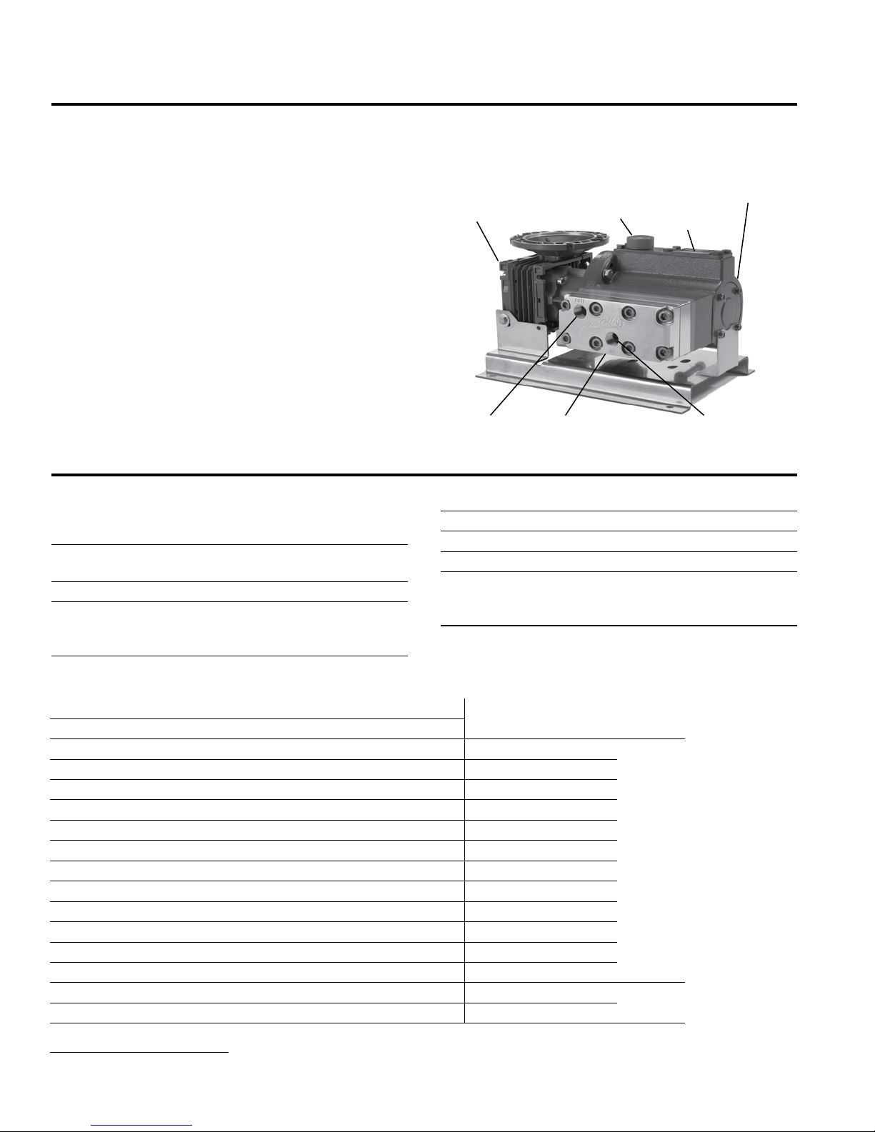
Component Identification
Pump Assembly
Hydraulic End
Reducer
Outlet
Inlet Port 1/2 inch NPT or BSPT
Discharge Port 1/2 inch NPT or BSPT
Shaft Rotation Bi-directional
Oil Capacity 1.1 US quart (1.05 liters)
Weight
Metallic Head: 51 lbs (23.1 kg)
Metallic Head with motor adapter: 57 lbs (25.9 kg)
Oil Fill Cap
Pump Assembly
Fluid End
ID Plate
Inlet
Gallons Per Hour (GPH) Maximum Flow at Designated Pressure
GPH Metallic Pump Heads
100 PSI (*) 500 PSI (*) 1500 PSI (*) 2500 PSI (*)
(¼) 1.85 (¼) 1.50 (¼) 1.15 (¼) 18 100:1
2.00
2.51
(¼) 2.36 (¼) 1.98 (¼) 1.60 (¼) 22.5 80:1
3.37 (¼) 3.21 (¼) 2.79 (¼) 2.36 (¼) 30 60:1
4.06 (¼) 3.88 (¼) 3.43 (¼) 2.97 (¼) 36 50:1
5.09 (¼) 4.89 (¼) 4.40 (¼) 3.88 (¼) 45 40:1
6.80 (¼) 6.58 (¼) 6.01 (¼) 5.39 (¼) 60 30:1
8.17 (¼) 7.94 (¼) 7.30 (¼) 6.60 (¼) 72 25:1
(¼) 9.62 (¼) 9.23 (¼) 8.41 (½) 90 20:1
10.23
13.66 (¼) 13.34 (¼) 12.46 (½) 11.44 (½) 120 15:1
(¼) 20.10 (¼) 18.90 (½) 17.50 (¾) 180 10:1
20.52
(¼) 26.86 (¼) 25.35 (½) 23.55 (1) 240 7.5:1
27.38
41.10 (¼) 40.37 (½) 38.24 (¾) 35.67 (1½) 360 5:1
(¼) 53.89 (½) 51.13 (1) 47.78 (2) 480 7.5:1
54.82
(¼) 80.91 (¾) 76.91 (1½) 72.00 (3) 720 5:1
82.26
*Required Motor HP
2
Pump
RPM
Gear
Ratio
Motor
RPM
1800
3600
P300-991-2400B
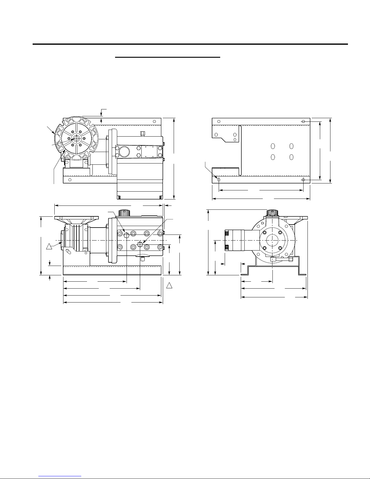
P300 Dimensions
OUT
IN
8.68
(220.5)
0.24
(6.1)
9.38
(238.3)
11.38
(289.1)
14.50
(368.3)
14.75
(374.6)
4.52
(114.8)
5.86
(148.8)
1.37
(34.8)
1
1/2" NPT or
1/2" BSPT
16.02
(406.9)
0.24
(6.1)
1/2" NPT or 1/2" BSPT
1
Note:
Worm Gear Reducer available
in the following ratios: 5:1, 7.5:1,
10:1, 15:1, 20:1, 25:1, 30:1, 40:1,
50:1, 60:1, 80:1, 100:1.
4.65
(118.1)
2.36
(59.9)
5.13
(130.3)
9.60
(243.8)
9.64
(244.9)
9.87
(250.7)
8.63
(219.2)
9.63
(244.6)
14.50
(368.3)
12.50
(317.5)
Ø0.41
(10.4)
4X
11.99
(304.5)
Ø6.50
(165.1)
NEMA 56C Flange
Pilot
Ø4.500
(114.3)
Bolt Circle
Ø5.875
(149.2)
NEMA
56C
Ø0.625
(15.88)
Square
Key
0.187
(4.75)
W0003
P300 Models with Metallic Pumping Head
304 Stainless Steel
316 Stainless Steel
Hastelloy® C
3
P300-991-2400B
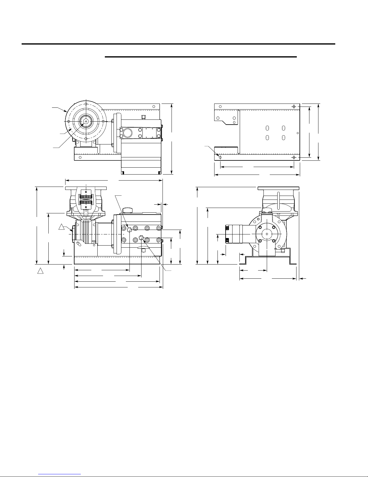
P300 Dimensions
OUT
IN
13.15
(334)
8.68
(220.5)
16.51
(419.4)
0.24
(6.1)
1.37
(34.8)
Ø7.00
(177.8)
11.99
(304.5)
8.63
(219.2)
9.63
(244.6)
13.14
(333.8)
9.60
(243.8)
5.13
(130.3)
2.36
(59.9)
4.65
(118.1)
9.64
(244.9)
0.48
(12.2)
12.50
(317.5)
Ø0.41
(10.4)
4X
14.50
(368.3)
NEMA 143/5TC Flange
Ø4.500 (114.3) Pilot
Ø5.875 (149.2) B.C.
NEMA 143/5TC
Ø0.875 (22.2)
0.187 (4.75) Square Key
1
1/2" NPT or
1/2" BSPT
1/2" NPT or
1/2" BSPT
9.38
(238.3)
11.38
(289.1)
14.50
(368.3)
5.86
(148.8)
4.52
(114.8)
15.07
(382.8)
1
Worm Gear Reducer
available in the following
ratios - 5:1, 7.5:1
Note:
2. Weight = 57 lbs (25.9 kg)
(no motor)
W0305
P300 Models with Metallic Pumping Head and Motor Adapter
304 Stainless Steel
316 Stainless Steel
Hastelloy® C
Inches (mm)
4
P300-991-2400B
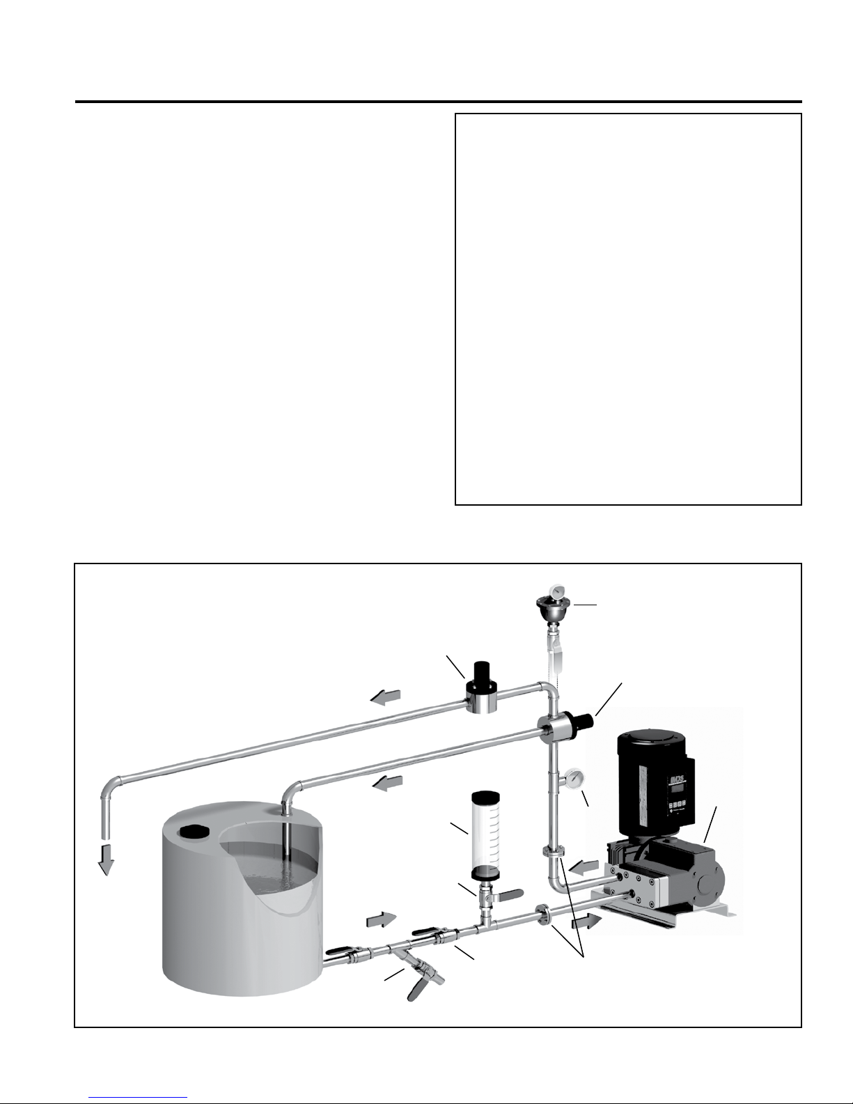
P300 Installation
P300
METERING PUMP
W0325
PULSATION
DAMPENER
(OPTIONAL)
CALIBRATION
CYLINDER
Y-STRAINER
ISOLATING VALVE
BALL VALVE
RELIEF
VALVE
FLANGES & MANIFOLDS
BACK PRESSURE
VALVE
(To process)
PRESSURE
GAUGE
Location
NOTE: The numbers in parentheses are Reference Numbers
located in the Parts List exploded views of this manual.
Locate the pump as close to the supply source as possible.
Install it in a lighted clean space where it will be easy to inspect
and maintain.
Motor and Controller
The P Series pump shaft can rotate in either direction, therefore
direction of motor shaft rotation is not critical.
Accessories
Consult installation drawing below for typical precision metering
fluid system components. Contact Wanner Engineering or the
distributor in your area for more details.
Important Precautions
Ad equate Fluid Suppl y. To avoid c avitati on and
premature pump failure, be sure that the pump will have
an adequate fluid supply and that the inlet line will not be
obstructed. See Inlet Piping on page 6.
Positive Displacement. This is a positive-displacement
pump. To avoid severe system damage if the discharge line
ever becomes blocked, install a relief valve downstream
from the pump. See Discharge Piping on page 6.
Safety Guards. Follow all codes and regulations regarding
installation and operation of the pumping system.
Shut-Off Valves. Never install shut-off valves between
the pump and discharge pressure regulator, or in the
regulator bypass line.
Consult the Factory for the following situations:
• Extreme temperature applications (above 160°F or
below 40°F)
• Pressure feeding of pumps
• Viscous or abrasive fluid applications
• Chemical compatibility problems
• Hot ambient temperatures (above 110°F)
5
P300-991-2400B
 Loading...