

Page 1
TM
P100 Metering Pump
Installation, Operation & Maintenance
P100-991-2400C
1204 Che stnut Avenue, Minneapo lis, MN 55403
Tel: (612) 332-5681 Fax: (612) 332-6937
Toll-fre e fax [US only]: (800) 332-6812
www.hydra-cell.com/metering
email: [email protected]
W0032B
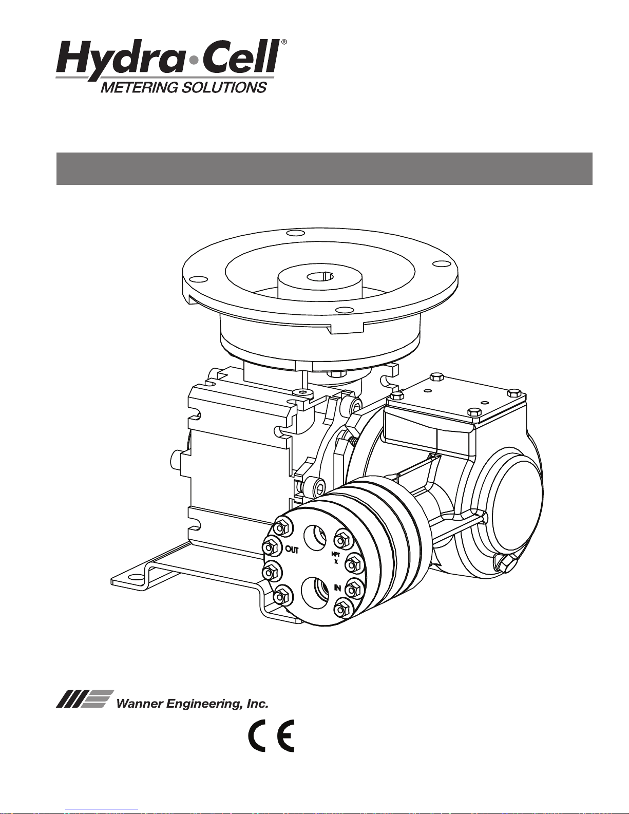
Metallic pump shown
Page 2
P100 Contents
W0032B
Page
Operation ................................................................................2
Specications ..........................................................................2
Dimensions .............................................................................4
Installation ...............................................................................5
Calibration ...............................................................................7
Maintenance ............................................................................7
Fluid End
Service .................................................................................8
Parts List .............................................................................10
Hydraulic End Parts List ........................................................12
Reducer Parts List.................................................................13
Troubleshooting .....................................................................14
Replacement Parts Kits ........................................................15
Warranty ................................................................................16
Hydra-Cell Metering Solutions Pumps are hydraulicallyactuated, hydraulically-balanced diaphragm metering pumps
that exceed API 675 performance standards of ±1% steady state
accuracy, ±3% linearity and ±3% repeatability.
Due to their multiple diaphragm design, the P Series
metering pumps, with the exception of the P100, provide virtually
“pulse-free” linear ow. Unlike conventional single diaphragm
metering pumps, this linear ow reduces the need for pulsation
dampeners and increases the reliability, performance, and
safety of the metering pump system.
Pump operation and plunger activation are accomplished
through a crankshaft (P100, P200 and P300) or wobble plate
(P400, P500 and P600). Horizontal disk check valves allow for
the pumping of particulates that ordinarily collect on vertical
ball check valves common to conventional metering pumps.
P Series pumps utilize speed to adjust ow rate through a
motor and variable-frequency drive (VFD), eliminating the need
for mechanical adjustment.
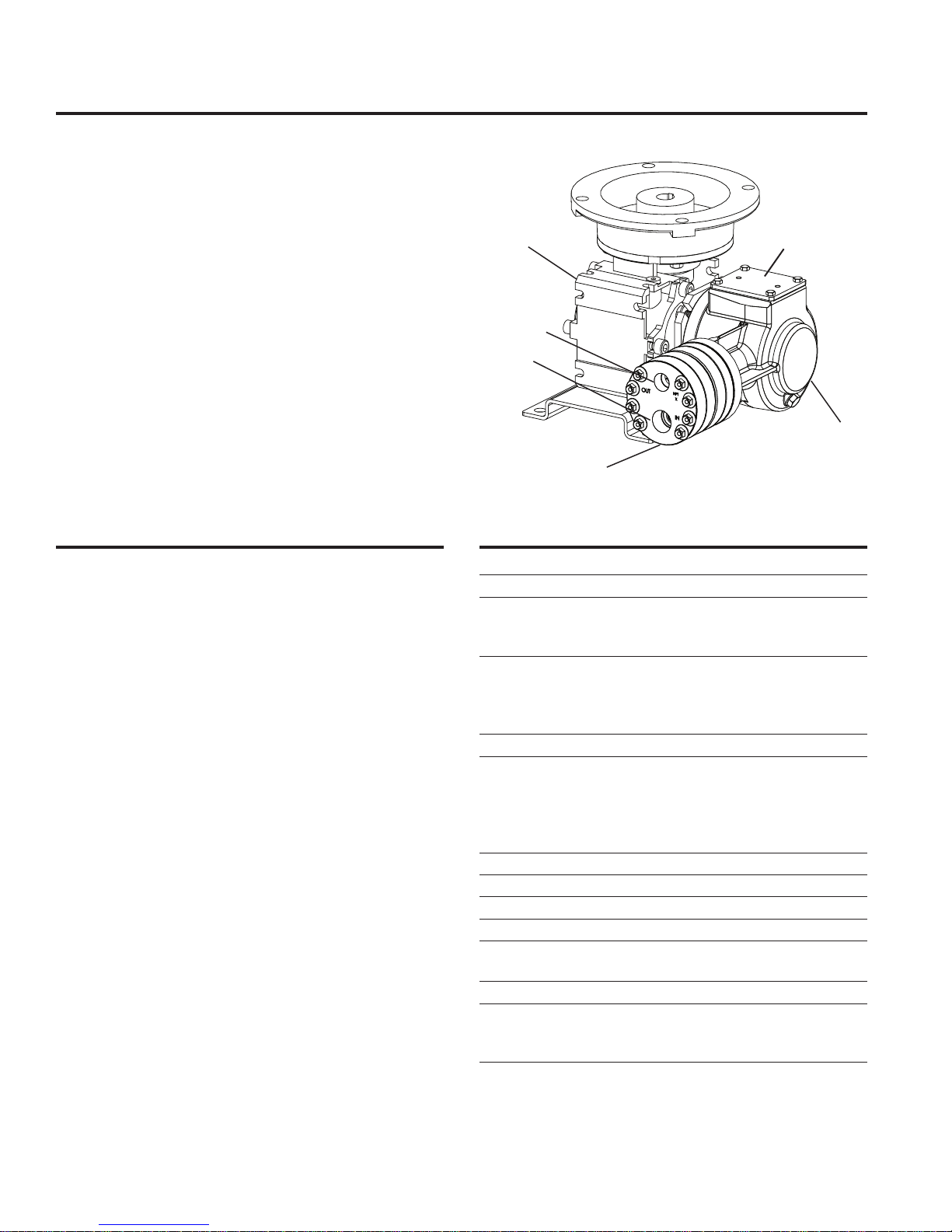
Component Identication
Reducer
Outlet
Inlet
Pump Assembly
Fluid End
Oil Cover/ID Plate
Pump Assembly
Hydraulic End
P100 SpecicationsP100 Operation
Diaphragms per Liquid End 1 (non Kel-Cell pistons)
Flow Control Electronic variable speed drive
Steady State Accuracy ±1%
Linearity ±3%
Repeatability ±3%
Maximum Pressure
Metallic Heads: 1500 psi (103 bar)
Non-Metallic Heads: PVDF: 350 psi (24 bar)
Polypropylene: 250 psi (17 bar)
Maximum Inlet Pressure 250 psi (17 bar)
Fluid Operating Temperatures*
Metallic Head: 250°F (121°C)
Non-Metallic Head: 140°F (60°C)
* Consult factory for correct component selection for
temperatures from 160˚F (71˚C) to 250˚F (121˚C).
Inlet Port 1/2 inch NPT or BSPT
Discharge Port 3/8 inch NPT or BSPT
Maximum Solids 200 microns
Shaft Rotation Bi-directional
Materials Used See Replacement Parts Kits Section
for individual pump materials.
Oil Capacity 1/8 US quart (0.12 liters)
Weight (less motor)
Metallic Heads: 21.2 lbs (9.6 kg)
Non-Metallic Heads: 19.1 lbs (8.7 kg)
2
P100-991-2400C
Page 3
P100 Specications (Cont’d)
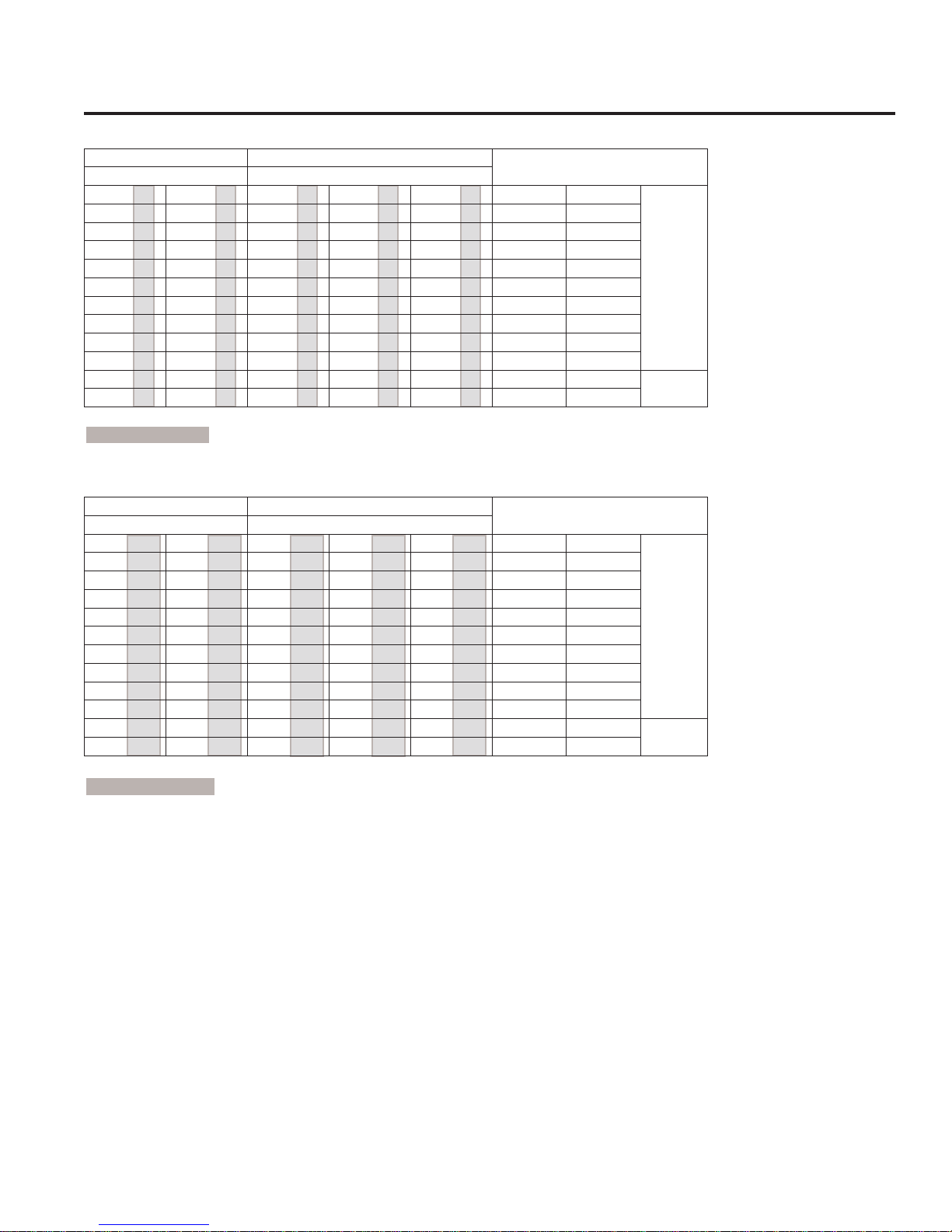
Performance Maximum Flow at Designated Pressure - Imperial *
All Pumps (gph) Metallic Pump Heads Only (gph)
100 psi 250 psi 500 psi 1000 psi 1500 psi
1.086 (½) 1.077 (¾) 1.058 (¾) 1.015 (¾) 0.981 (¾) 30 60:1
1.316 (½) 1.300 (¾) 1.273 (¾) 1.220 (¾) 1.184 (¾) 36 50:1
1.630 (½) 1.628 (½) 1.607 (¾) 1.535 (¾) 1.492 (¾) 45 40:1
2.192 (½) 2.182 (½) 2.148 (½) 2.056 (½) 2.000 (¾) 60 30:1
2.643 (½) 2.626 (½) 2.582 (½) 2.473 (½) 2.405 (½) 72 25:1
3.318 (½) 3.291 (½) 3.232 (½) 3.099 (½) 3.014 (½) 90 20:1
4.444 (½) 4.400 (½) 4.316 (½) 4.141 (½) 4.028 (½) 120 15:1
6.695 (½) 6.618 (½) 6.483 (½) 6.226 (½) 6.057 (½) 180 10:1
8.947 (½) 8.836 (½) 8.651 (½) 8.311 (½) 8.085 (½) 240 7.5:1
13.45 (½) 13.27 (½) 12.99 (½) 12.48 (½) 12.14 (¾) 360 5:1
17.95 (½) 17.71 (½) 17.32 (½) 16.65 (¾) 16.20 (¾) 480 7.5:1
26.96 (½) 26.58 (½) 25.99 (¾) 24.99 (¾) 24.31 (1) 720 5:1
*Capacity data shown is for pumps with elastomeric diaphragms. Consult factor y for performance characteristics of pumps with PTFE diaphragms.
( ) Required Motor hp
Performance Maximum Flow at Designated Pressure - Metric *
All Pumps (lpm) Metallic Pump Heads Only (lpm)
7 bar 17 bar 34 bar 69 bar 103 bar
3.425 (0.18) 3.396 (0.18) 3.337 (0.18) 3.203 (0.18) 3.095 (0.55) 25 60:1
4.150 (0.18) 4.102 (0.18) 4.016 (0.18) 3.850 (0.18) 3.735 (0.55) 30 50:1
5.140 (0.18) 5.135 (0.18) 5.068 (0.18) 4.841 (0.25) 4.708 (0.55) 37.5 40:1
6.916 (0.18) 6.884 (0.18) 6.777 (0.18) 6.486 (0.25) 6.307 (0.25) 50 30:1
8.336 (0.18) 8.283 (0.18) 8.145 (0.18) 7.801 (0.25) 7.587 (0.25) 60 25:1
10.47 (0.18) 10.38 (0.18) 10.20 (0.18) 9.774 (0.25) 9.507 (0.25) 75 20:1
14.02 (0.18) 13.88 (0.18) 13.61 (0.18) 13.06 (0.37) 12.71 (0.37) 100 15:1
21.12 (0.18) 20.88 (0.18) 20.45 (0.18) 19.64 (0.37) 19.11 (0.37) 150 10:1
28.22 (0.18) 27.87 (0.18) 27.29 (0.18) 26.22 (0.37) 25.50 (0.37) 200 7.5:1
42.43 (0.18) 41.87 (0.18) 40.96 (0.18) 39.37 (0.37) 38.30 (0.55) 300 5:1
56.63 (0.37) 55.86 (0.37) 54.64 (0.37) 52.53 (0.55) 51.10 (0.55) 400 7.5:1
85.04 (0.37) 83.85 (0.37) 81.98 (0.55) 78.84 (0.55) 76.70 (0.55) 600 5:1
*Capacity data shown is for pumps with elastomeric diaphragms. Consult factor y for performance characteristics of pumps with PTFE diaphragms.
( ) Required Motor kW
Pump
rpm
Pump
rpm
Gear
Ratio
Gear
Ratio
Motor
rpm
1800
3600
Motor
rpm
1500
3000
3
P100-991-2400C
Page 4
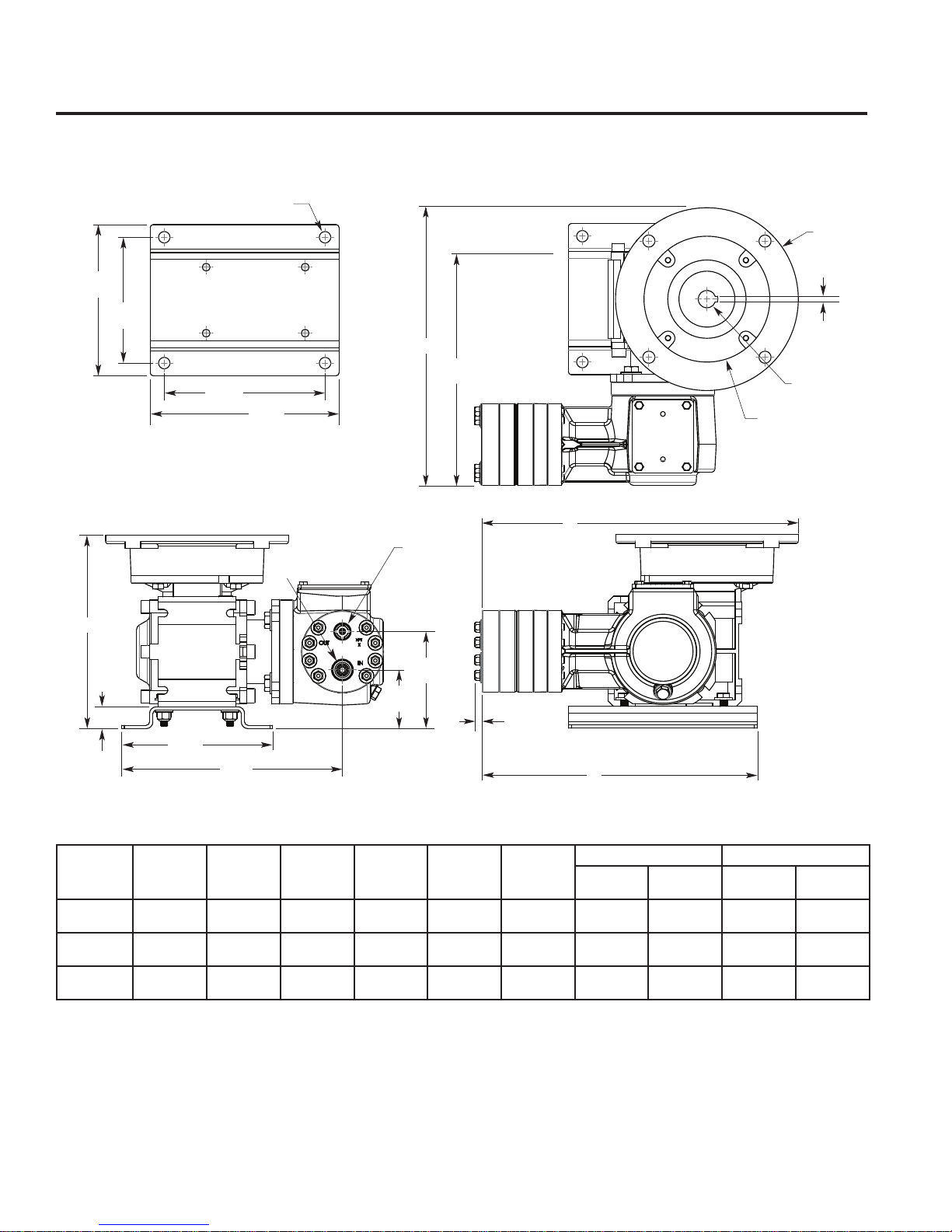
5.75
(146.1)
7.27
(184.7)
5.40
(137.2)
4.50
(114.3)
Ø0.41
(10.4)
(4X)
0.78
(19.8)
5.40
(137.2)
7.90
(200.6)
2.10
(53.3)
3.47
(88.1)
1/2" NPT or
1/2" BSPT
3/8" NPT or
3/8" BSPT
E
9.36
(237.8)
A
B
C
F
D
H
0.26
(6.7)
G
W0035A
P100 Dimensions
P100 Models: Metallic and Non-Metallic
Input
Frame Size
NEMA 56C
IEC 63 B5
IEC 71 B5
A B C D E
9.93 (252.2)
9.42 (239)
9.81 (249.2)
Ø 6.54
(Ø 166)
Ø 5.51
(Ø 140)
Ø 6.30
(Ø 160)
Dimensions in Inches (Millimeters)
Ø 4.50
(Ø 114.3)
Ø 3.74
(Ø 95)
Ø 4.33
(Ø 110)
(Ø 15.7)
(Ø 11)
(Ø 14)
Ø .62
Ø .43
Ø .55
Ø 6.92
(Ø 175.8)
Ø 6.74
(Ø 171.3)
Ø 6.74
(Ø 171.3)
(Square
Key)
0.187 (4.75)
0.157 (4)
0.196 (5)
F
Metallic
Pump Head
(2 87. 4)
(275. 3)
(285.5)
G H
11. 36
10.84
11. 24
Plastic
Pump Head
11. 61
(294.9)
11. 09
(281.7)
11. 49
(291. 8)
Metallic
Pump Head
9.84 (250)
9.84 (250)
9.84 (250)
Plastic
Pump Head
10.09
(256 .3)
10.09
(256 .3)
10.09
(256 .3)
4
P100-991-2400C
Page 5
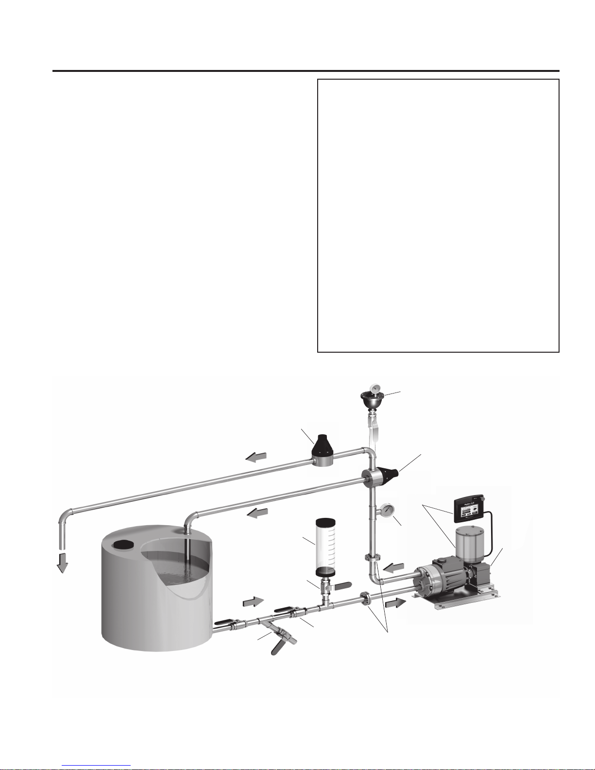
P100 Installation
W0323A
(To process)
Pulsation
Dampener
(Optional)
Relief
Valve
Flanges & Manifolds
Ball Valve
Y-Strainer
Isolating
Valve
Calibration
Cylinder
Pressure
Gauge
Back Pressure
Valve
P-Series
Metering Pump
Typical Metering Installation
Controllers
& Motors
Location
Locate the pump as close to the supply source as possible.
Install the pump system in a lighted clean space where it will be
easy to inspect and maintain.
Motor and Controller
The P Series pump shaft can rotate in either direction,
therefore direction of motor shaft rotation is not critical.
Flow rate is determined by motor speed, which is controlled
using an inverter duty constant torque motor and VFD. Flow
rate functions can also be easily controlled using the Hydra-Cell
Control Freak and appropriate motor.
Accessories
Consult installation drawing below for typical metering uid
system components. Contact Wanner Engineering or the
distributor in your area for more details.
Important Precautions
Adequate Fluid Supply. To avoid cavitation and
premature pump failure, be sure that the pump will have
an adequate uid supply and that the inlet line will not be
obstructed. See Inlet Piping.
Positive Displacement. This is a positive-displacement
pump. To avoid severe system damage if the discharge line
ever becomes blocked, install a relief valve downstream
from the pump. See Discharge Piping.
Safety Guards. Follow all codes and regulations regarding
installation and operation of the pumping system.
Shut-O Valves. Never install shut-o valves between
the pump and relief valve, or in the regulator bypass line.
Consult the Factory for the following situations:
• Extreme temperature applications (above 160°F or
below 40°F)
• Pressure feeding of pumps
• Viscous or abrasive uid applications
• Chemical compatibility problems
• Hot ambient temperatures (above 110°F)
5
P100-991-2400C
Page 6

P100 Installation (Cont’d)
Safety Precautions
General remarks
These safety / installation instructions contain fundamental
information and precautionary notes and must be kept available
to all associated with the operation of the pump. Please read
them thoroughly prior to installation, electrical connection and
commissioning of the unit. It is imperative that all other operating
instructions relating to the components of individual units are
followed.
These safety / installation instructions do not take local
regulations into account. The operator must ensure that such
regulations are observed by all, including the personnel carrying
out the installation.
Each pump must be labeled by the end user to warn of any
hazards that the system process may produce; e.g. corrosive
chemicals or hot process etc.
All personnel involved in the operation, maintenance, inspection
and installation of the pump must be fully qualied to carry out
the work. The personnel’s responsibilities, competence and
supervision must be clearly dened by the operator. To the extent
that if the personnel in question is not already in possession
of the requisite know how, appropriate training and instruction
must be provided. In addition, the operator is responsible for
ensuring that the contents of the operating instructions are fully
understood by all the responsible personnel.
When installing a Hydra-Cell pump in conjunction with a motor
or motor and frequency controller the relevant manuals must
be referred to for electromagnetic compatibility. The installation
should conform to EN 61800 and EN 60204 as applicable.
All safety instructions in this manual and all relevant local health
and safety regulations must be followed.
Attention must be paid to the weight of the pump before
attempting to lift either manually or selecting appropriate lifting
equipment.
Inlet Piping
CA UT ION : Wh en pumpi ng at t emp era tures above 160° F (71°C),
use a pressure-feed system.
Provide for permanent or temporary installation of a compound
pressure gauge to monitor the inlet pressure. To maintain
maximum ow, vacuum at the pump inlet should not exceed
7 in. Hg (180 mm Hg).
Note: PTFE diaphragms require a minimum suction
pressure of 15 psi.
Do not supply more than one pump from the same inlet line.
Supply Tank
Use a supply tank that is large enough to provide time for any
trapped air in the uid to escape. The tank size should be at
least twice the maximum pump ow rate.
Install a separate inlet line from the supply tank to each pump.
Place a cover over the supply tank, to prevent foreign objects
from falling into it.
Hose Sizing and Routing
To minimize acceleration head and frictional losses, size the
suction line at least one size larger than the pump inlet, and
keep the suction line as short and direct as possible.
Recommendations:
• Keep inlet lines less than 3 ft. (1 m) long
• Use at least 5/8” (16 mm) I.D. inlet hose
• Minimize ttings (elbows, valves, tees, etc.)
Support the pump and piping independently.
Inlet Piping (Pressure Feed)
Provide for permanent or temporary installation of a pressure
gauge to monitor the inlet pressure. Pressure at the pump inlet
should not exceed 250 psi (17.3 bar). For higher pressures install
a pressure reducing valve. Do not supply more than one pump
from the same inlet line.
Note: System back pressure must exceed the pump inlet
pressure by at least 15 psi (1 bar) in order to prevent ow
thru.
Discharge Piping
Hose and Routing
Use the shortest, most-direct route for the discharge line.
Select pipe or hose with a working pressure rating of at least
1.5 times the maximum system pressure. Example: Select a
1500 psi (103 bar) W.P. rated hose for a system to be operated
at 1000 psi (69 bar) gauge pressure.
Support the pump and piping independently.
Pressure Regulation
Install a pressure relief valve in the discharge line. Bypass
pressure must not exceed the pressure limit of the pump.
Size the valve so that, when fully open, it will be large enough
to relieve the full capacity of the pump without overpressurizing
the system.
Locate the valve as close to the pump as possible and ahead
of any other valves.
Adjust the pressure relief valve to no more than 10% over the
maximum working pressure of the system. Do not exceed the
manufacturer’s pressure rating for the pump or valve.
Route the bypass line to the supply tank.
CA UT ION: Never in sta ll shut o valves in th e by pas s line or
between the pump and pressure regulator or relief valve.
Provide for permanent or temporary installation of a pressure
gauge to monitor the discharge pressure at the pump.
Minimum Discharge Pressure
To ensure proper capacity control, a minimum discharge
pressure of 50 psi (3.5 bar) is recommended.
6
P100-991-2400C
Page 7

P100 Installation (Cont’d)
Initial Start-Up Procedure
Note: Th e nu mbe rs in pa ren these s ar e Re fer enc e Nu mbe rs
located in the Parts List exploded views of this manual.
Note: The oil reservoir in the pump housing is lled and
sealed at the factory. To check the oil level, remove the
cover (70) and slowly lift the diaphragm (71). Also see
Fill and Seal the Oil Reservoir Paragraph in the Fluid End
Service Section.
Before starting the pump, be sure that:
1. All shut-o valves are open, and pump has adequate supply
of uid.
2. All connections are tight.
3. Oil reservoir beneath diaphragm (71) is completely full.
4. Open priming valve on system back pressure valve so pump
starts under minimum pressure. See Typical Metering
Installation drawing.
Turn on power to pump motor and:
1. Check inlet pressure or vacuum. To maintain maximum ow,
pump inlet should be under ooded suction conditions at all
times. Inlet pressure must not exceed 250 psi (17.3 bar).
2. Observe any erratic noise or ow.
3. Jog pump on and o until uid coming from priming valve
is air-free.
4. Close priming valve.
5. Perform pump calibration. See Calibration Procedure.
Calibration
Not e: Ea ch me ter in g pu mp or pu mp syst em must be ca libra ted
to dete rmi ne th e pu mp spee d re quire d fo r th e de sired ow ra te.
Accurate calibration
system conditions. When calibrating the pump or system, it is
useful to plot capacity curves for future reference. Observe on
the curve, that pump capacity decreases slightly as discharge
pressure increases.
In order to achieve the best possible results, perform calibration
under actual process conditions. Follow these steps:
1. Run pump for 20 minutes at actual process conditions. If
process system cannot be used, circulate back to supply tank
through pressure relief valve (see Typical Metering Installation
drawing). If required system pressure is less than 50 psi (3.5
bar) back pressure valve must be installed and set to produce
minimum of 50 psi (3.5 bar) pressure at pump head.
2. Determine maximum pump speed required for all system
conditions that need to be satised. Measure pump delivery
at this maximum speed using system calibration cylinder, ow
meter, or similar container. This is the “rated capacity” for pump.
3. Measure pump delivery at 100%, 75%, 50%, 25%, and 10% of
maximum speed just determined. Let pump run for 5 minutes
at each speed setting before taking capacity measurement.
depends on pump discharge pressure and
P100 Maintenance
Periodically
CAUT ION: Do not turn th e dr ive sh aft whi le the oi l reser voi r
is empty.
CAUTION: Do not leave contaminated oil in the pump
housi ng or le ave th e hous ing empty. Re move cont ami nated
oil as soon as discovered and replace with clean oil.
1. Check inlet pressure periodically with gauge.
2. Change oil according to hours guidelines in table.
3. Change oil as follows:
a. Remove drain plug (69), and allow oil and
contaminants to drain completely. Catch oil
and dispose of properly.
b. Use suitable Hydra-Oil for the application and pump
components.
c. There should be no trapped air under oil reservoir
diaphragm (71). Also see: Fill and Seal the Oil
Reservoir Paragraph in the Fluid End Service
Section.
Pump Operation Hours Between Oil Changes
at Various Process Fluid Temperatures
Pressure (32°C) (60°C) (82°C)
Metallic Pump Head
<1000 psi (70 bar) 6,000 4,000 2,000
<1500 psi (100 bar) 3,000 2,000 1,500
Non-Metallic Pump Head
<250 psi (17 bar) 3,000 2,000 —
Note: Minimum oil viscosity for proper hydraulic end
lub ric atio n is 16 - 20 cS T (8 0-100 SSU ). P- Serie s r e pla cem ent
parts kits (complete kits and diaphragm kits) include
suitable oil for each P Series pump conguration.
CAUTION: If you are losing oil but don’t see any external
leakage, or if the oil becomes discolored and contaminated,
the diaphragm (22) may be damaged. Refer to the Fluid End
Service and Troubleshooting Sections. Do not operate the
pump with a damaged diaphragm.
7
<90°F <139°F <180°F
P100-991-2400C
Page 8

P100 Fluid End Service
Note: The reference numbers in parentheses are shown
in the Fluid End Parts List.
This se ction ex plain s ho w to di sasse mble an d in spect all easily serviceable parts of the pump uid end.
CAUTION: Disassembly of the hydraulic end of the pump
should be performed only by a qualied technician. For
assistance, contact Wanner Engineering (612-332-5681) or
the distributor in your area.
1. Remove Support Plate (2)/
Manifold (3)
Not e: Suppo r t Pl ate is used on non- m eta ll ic pu mp s on ly.
a. Remove eight bolts (1) around support plate (2)/manifold (3),
b. Remove support plate/manifold.
c. Inspect support plate/manifold for warping or wear around
inlet and outlet ports. If wear is excessive, replace or
return to Wanner Engineering for resurfacing.
Place a straightedge across manifold to check if it is
warped. If warped replace.
2. Inspect Valves (4-17)
The inlet and outlet valve assemblies are dierent (inlet
va lve is la rger) an d fa ce oppo site direct ions. Inspe ct each
valve assembly as follows:
a. Check spring retainers (4,17), and replace if worn.
b. Check valve springs (5,16). If shorter than new spring,
replace (do not stretch old spring).
c. Check valve discs (6,15). If worn excessively, replace.
d. Remove valve seats (9,13) with seat puller provided in
Wanner Tool Kit (Part No. A03-175-1105).
Inspect valve seats for wear, and replace if necessary.
New O-rings (8,12) should be installed.
e. Check dampening washer (10), and replace if worn.
f. Reinstall inlet and outlet valve assemblies:
• Clean valve ports and shoulders with emery cloth, and
lubricate with lubricating gel or petroleum jelly (do not use
petroleum products when installing EPDM O-rings).
• Install O-rings (8,12) on valve seats (9,13).
• Inlet Valve. Insert spring retainer (17) into valve plate
(21). Then in sert spr ing (16), valve (15), Tetra Se al ® (14)
and valve seat (13)..
• Outlet Valve. Insert dampening washer (10), valve
seat (9) (for non-metallic retainers only), Tetra Seal® (7),
valve (6), spring (5), and spring retainer (4).
3. Inspect and Replace
Diaphragm (22)
Note: Oil escaping from behind diaphragm is
possible during the following steps.
a. Use 3 mm Allen wrench to remove two capscrews (20)
from valve plate (21).
b. Lift diaphragm (22) by one edge, and turn pump shaft
(use the shaft rotator from the Wanner Tool Kit)
until diaphragm moves up to “top dead center”. This will
expose machined cross holes in plunger shaft behind
diaphragm.
c. Insert plunger holder (from the Wanner Tool Kit) through
one of machi ne d cr oss ho les to hold di aphra gm up. Don’t
remove tool until new diaphragm is installed in step g
below.
d. Unscr ew diaphr ag m (22). Use 8 mm or 5/16 in . open- end
wrench and turn counterclockwise.
e. Inspect diaphragm (22) carefully. A damaged diaphragm
generally indicates a pumping system problem. Replacing
diaphragm will not solve the larger problem. Inspect
diaphragm for the following:
• Puncture. Usually caused by sharp foreign object in
uid.
• Diaphragm pulled away from sides. Usually caused
by uid being frozen in pump, or by over-pressurization
of pump.
• Diaphragm becoming sti and losing exibility.
Usually caused by pumping uid that is incompatible with
diaphragm material.
• Diaphragm edge chewed away. Usually caused by
over-pressurizing system.
CAUTION: If a diaphragm has ruptured and foreign
mat er ial or wa ter ha s en ter ed the oi l re ser voi r, do not
operate the pump. Check the diaphragm, then ush
the reservoir completely (see Flush Contaminant
from Hy dr aul ic End pa ragra ph) an d rell it wi th fres h
oil. Ne ve r le t the pump st and wit h fo reign mat eri al or
water in the reservoir, or with the reservoir empty.
f. Clean away any spilled oil. Apply Loctite® 242 thread
locker to threads of new diaphragm (22) (or old one).
g. Insta ll diaphr ag m (22) an d ti ghten to 10 in -lb s (113 N-c m).
8
P100-991-2400C
Page 9

P100 Fluid End Service (Cont’d)
4. Flush Contaminant from
Hydraulic End
(Only if diaphragm has ruptured)
a. With valve plate and manifold still removed (see above),
remove drain plug (69), four screws (72), cover (70), and
oil diaphragm (71). Allow all oil and contaminant to drain
out.
b. Fill reservoir with compatible solvent. Manually turn pump
shaft to circulate compatible solvent and drain. Use the
shaft rotator provided in Wanner Tool Kit (Part No. A03175-1105). Dispose of contaminated uid properly.
CA UT ION: If you have an EPDM di aph ragm, or if food
grade oil is in the reservoir, do not use kerosene or
solvents. Instead, ush with the same lubricant that
is in the reservoir.
c. Repeat step b ushing procedure.
d. Fill reservoir with fresh oil and manually turn pump shaft
to circulate oil. Drain oil.
Note: P Series replacement parts kits (complete kits
and diaphragm kits) include the correct oil for each
specic P Series pump conguration.
e. Rell reservoir with fresh oil. If oil appears milky, there is
still contaminant in reservoir. Repeat steps c and d until
oil appears clean.
5. Prime Hydraulic Cell
a. I f ne cessa r y, wi th pump hori zo ntal, re mo ve fo ur screw s (72),
cover (70), and oil diaphragm (71).
b. Fill pump housing reservoir (62) with correct Hydra oil for
application.
Note: P Series replacement parts kits (complete kits
and diaphragm kits) include the correct oil for each
specic P Series pump conguration.
c. Air behind the diaphragm must be forced out by turning
shaft and pumping piston. Any air in the hydraulic end
will cause the pump to have loss in ow and re-priming
will be necessary.
d. Turn sh aft unt il bubb le- free o w of oil co me s fr om behi nd
diaphragm. Use the shaft rotator provided in Wanner
Tool Kit (Part No. A03-175-1105). Make sure oil level in
reservoir doesn’t get to low. Add oil as necessary. If oil
gets too lo w, ai r wi ll be dr aw n into hy dr aulic side of pi ston.
e. When oil is bubble-free, refresh oil reservoir.
f. Install oil diaphragm and cover, using four screws.
g. Wipe o excess oil on pump housing.
6. Reinstall Valve Plate (21) and
Support Plate (2) / Manifold (3)
Not e: Suppo r t Pl ate is used on non- m eta ll ic pu mp s on ly.
a. Reinstall valve plate (21) on diaphragm plate (24).
b. Reinstall O-rings (18,19) on valve plate (21). Use
petroleum jelly or lubricating gel to hold them in place
(do not use petroleum products when installing EPDM
O-rings).
c. Reinstall support plate (2) / manifold (3) onto valve plate.
d. Insert eight bolts (1) around edge of manifold, and
alternately tighten opposite bolts until all are secure.
Torque to 90 in-lbs (1017 N-cm).
e. Recheck all bolts for tightness.
7. Fill Oil Reservoir
a. I f ne cessa r y, wi th pump hori zo ntal, re mo ve fo ur screw s (72),
cover (70), and oil diaphragm (71). The oil diaphragm
extends into pump housing reservoir approximately
1/4 in. to 3/8 in.
b. Add oil so that when diaphragm is set in reservoir all air
is pushed out. Take care not to allow any oil overow.
This may result in an apparent oil leak when the pump is
put into use.
c. Install reservoir cover (70) using four screws (72).
d. Wipe o excess oil on pump housing.
Note: Th e oi l di aph ragm wi ll ex up an d down sligh tly
as the pump operates. The vent holes in the cover
allow this to freely occur. Do not block vent holes.
9
P100-991-2400C
Page 10
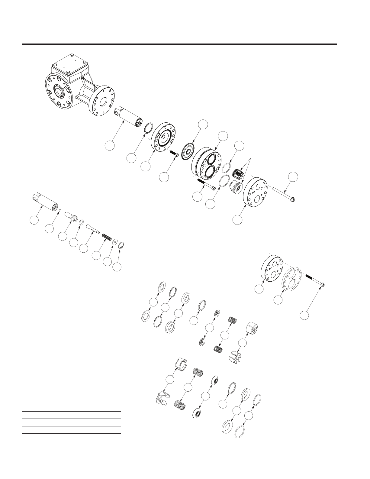
W0039A
Outlet
Valve
Plastic
Retainer
Metal
Retainer
17
Plastic
Retainer
Inlet
Valve
Metal
Retainer
16
12
15
13
14
10
8
4
9
6
7
5
Detail “B”
(Valve Assemblies)
P100 Fluid End Parts List
W0040A
3
Detail C
(Nonmetallic
Pump Head)
2
1
W0038A
33
Detail A
(Piston Assembly)
32
31
30
26
29
28
27
W0037A
22
Piston Assembly
(see Detail A)
34
25
24
21
19
Valve Assemblies
(see Detail B)
23
1
20
18
(see Detail C)
3
Bolt Torque Specications
Ref. No. in-lbs N-cm
1 90 1,017
20 14 158
22 10 113
23 14 158
10
P100-991-2400C
Page 11

P100 Fluid End Parts List (Cont’d)
Ref. Quantity/
No. Part Number Description Pump
1 G20-024-2011 Bolt, Hex-hd, SST................................8
2 F20-100-1033 Plate, Manifold support* ......................1
3 F20-004-1010 Manifold, Brass, NPT ..........................1
F20-004-1012 Manifold, 316 SST, NPT ......................1
F20-004-1017 Manifold, Hastelloy C, NPT .................1
F20-004-1050 Manifold, Polypropylene, NPT ............1
F20-004-1053 Manifold, PVDF, NPT ..........................1
G20-004-1010 Manifold, Brass, BSPT ........................1
G20-004-1012 Manifold, 316 SST, BSPT ....................1
G20-004-1017 Manifold, Hastelloy C, BSPT ...............1
G20-004-1050 Manifold, Polypropylene, BSPT ..........1
G20-004-1053 Manifold, PVDF, BSPT ........................1
4 D03-023-1017 Retainer, Outlet valve spring,
Hastelloy C ..........................................1
D03-023-2317 Retainer, Outlet valve spring,
polypropylene ......................................1
D03-023-2318 Retainer, outlet valve spring, PVDF ....1
5 D03-022-3113 Valve Spring, Outlet, Hastelloy C ........1
D03-022-3114 Valve Spring, Outlet, Elgiloy ................1
6 D03-021-1011 Outlet Valve, Nitronic...........................1
D03-021-1017 Outlet Valve, Hastelloy C ....................1
D03-021-3300 Outlet Valve, Ceramic .........................1
7 D03-092-2110 Tetra Seal®, Outlet, Buna-N ...............1
D03-092-2111 Tetra Seal®, Outlet, FKM ....................1
D03-092-2112 Tetra Seal®, Outlet, neoprene ............1
D03-092-2113 Tetra Seal®, Outlet, EPDM .................1
D03-035-2119 Tetra Seal®, Outlet, PTFE ..................1
8 D03-035-2112 O-ring, Outlet valve seat, neoprene ....1
D03-035-2113 O-ring, Outlet valve seat, EPDM .........1
D03-035-2118 O-ring, Outlet valve seat, PTFE ..........1
D25-046-2110 O-ring, Outlet valve seat, Buna-N .......1
D25-046-2111 O-ring, Outlet valve seat, FKM ...........1
9 D03-020-1001 Valve Seat, Outlet, 316 SST ................1
D03-020-1017 Valve Seat, Outlet, Hastelloy C ...........1
D03-020-3300 Valve Seat, Outlet, ceramic .................1
D15-020-2016 Valve Seat, Outlet, tungsten carbide ..1
10 D03-125-2317 Washer, Outlet dampening,
polypropylene ......................................1
D03-125-2318 Washer, Outlet dampening, PVDF ......1
12 D10-035-2110 O-ring, Inlet valve seat, Buna-N..........1
D10-035-2111 O-ring, Inlet valve seat, FKM ..............1
D10-035-2112 O-ring, Inlet valve seat, neoprene .......1
D10-035-2113 O-ring, Inlet valve seat, EPDM ............1
D10-035-2118 O-ring, Inlet valve seat, PTFE .............1
13 D10-020-1011 Valve Seat, Inlet, 316 SST ..................1
D10-020 -1017 Valve Seat, Inlet, Hastelloy C ..............1
D10-020 -3300 Valve Seat, Inlet, ceramic ...................1
14 D10-092-2110 Tetra Seal®, Inlet, Buna-N ..................1
D10-092-2111 Tetra Seal®, Inlet, FKM .......................1
D10-092-2112 Tetra Seal®, Inlet, neoprene ...............1
D10-092-2113 Tetra Seal®, Inlet, EPDM ....................1
D10-092-2118 Tetra Seal®, Inlet, PTFE .....................1
Ref. Quantity/
No. Part Number Description Pump
15 D10-021-1011 Inlet Valve, Nitronic .............................1
D10-021-1017 Inlet Valve, Hastelloy C .......................1
D10-021-3300 Inlet Valve, Ceramic ............................1
16 D10-022-3117 Valve Spring, Inlet, Elgiloy...................1
D10-022-3123 Valve Spring, Inlet, Hastelloy C ...........1
17 D10-023-1017 Retainer, Inlet valve spring,
Hastelloy C ..........................................1
D10-023-2327 Retainer, Inlet valve spring,
polypropylene ......................................1
D10-023-2328 Retainer, Inlet valve spring, PVDF ......1
18 F20-074-2110 O-ring, Inlet manifold, Buna-N ............1
F20-074-2111 O-ring, Inlet manifold, FKM .................1
F20-074-2112 O-ring, Inlet manifold, neoprene .........1
F20-074-2113 O-ring, Inlet manifold, EPDM ..............1
F20-074-2118 O-ring, Inlet manifold, PTFE ...............1
19 D10-034-2110 O-ring, Outlet manifold, Buna-N .........1
D10-034-2111 O-ring, Outlet manifold, FKM ..............1
F20-073-2112 O-ring, Outlet manifold, neoprene ......1
F20-073-2113 O-ring, Outlet manifold, EPDM ...........1
F20-073-2118 O-ring, Outlet manifold, PTFE ............1
20 G20-029-2010 Cap Screw, Soc-hd .............................2
21 F20-003-1010 Valve Plate, Brass ...............................1
F20-003-1012 Valve Plate, 316 SST ...........................1
F20-003-1017 Valve Plate, Hastelloy C ......................1
F20-003-1050 Valve Plate, Polypropylene .................1
F20-003-1053 Valve Plate, PVDF ...............................1
22 D03-018-1212 Diaphragm, Neoprene .........................1
D03-018-1213 Diaphragm, EPDM ..............................1
D03-018-1215 Diaphragm, FKM .................................1
D03-018-1218 Diaphragm, PTFE ...............................1
D03-018-1220 Diaphragm, Buna-N ............................1
D03-018-1225 Diaphragm, Aas .................................1
23 G20-088-2010 Cap-Screw, Soc-hd .............................2
24 F20-002-1010 Diaphragm Plate..................................1
25 D03-075-2110 O-ring, Diaphragm plate, Buna-N .......1
26 D03-048-2210 Snap Ring ............................................1
27 D03-049-1000 Washer ................................................1
28 D03-045-3110 Spring, Sleeve valve............................1
D03-045-3111 Spring, Sleeve valve for PTFE
diaphragm ...........................................1
29 D03-044-1000 Valve Plunger ......................................1
30 D03-034-2110 O-ring, Valve cylinder, Buna-N ...........1
31 D03-043-1000 Valve Cylinder .....................................1
32 D10-015-3010 Ball ......................................................1
33 D03-014-1004 Piston** ................................................1
34 D03-014-1210 Piston Assembly**(1) ...........................1
* For use with Non-Metallic Pump Head models only.
** Non Kel-Cell.
(1) Piston Assembly includes: items 26 through 33.
11
P100-991-2400C
Page 12
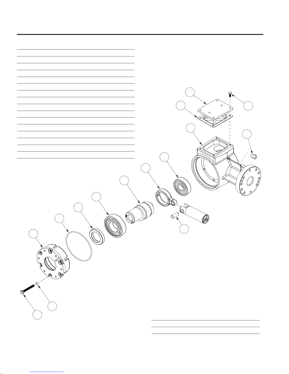
W0042A
54
55
56
57
58
59
60
62
61
53
52
69
71
70
72
P100 Hydraulic End Parts Lists
Ref. Quantity/
No. Part Number Description Pump
52 G20-086-2010 Screw, Cap, hex-hd, ange .................6
53 F20-036-2110 O-ring, Back cover screw, Buna-N .....6
54 G2 0-131-1010 Cover ...................................................1
55 F20-037-2110 O-ring, Cover, Buna-N ........................1
56 F20-031-2110 Seal, Buna-N .......................................1
57 D03-010-2910 Back Bearing .......................................1
58 F20-009-1003 (X) Hollow Shaft, 5/8” ID .....................1
59 D03-132-1000 Connecting Rod ..................................1
60 F20-010-2910 Front Bearing .......................................1
61 D03-133-1000 Pin .......................................................1
62 G20-001-1033 Pump Housing ....................................1
65 D10-085-2210 Key, Shaft ............................................1
69 D10-038-2210 Plug, Drain ...........................................1
70 F20-105-1020 Cover/Nameplate, Oil reservoir, SST ..1
71 F20-091-1010 Gasket, Oil reservoir ...........................1
72 G20-090-2010 Screw, Cap, hex-hd .............................4
Hydraulic End Service
CAUTION: Disassembly of the hydraulic end of the pump
should be performed only by a qualied technician. For
assistance, contact Wanner Engineering (612-332-5681) or
the distributor in your area.
Bolt Torque Specications
Ref. No. in-lbs N-cm
52 14 158
72 10 113
12
P100-991-2400C
Page 13
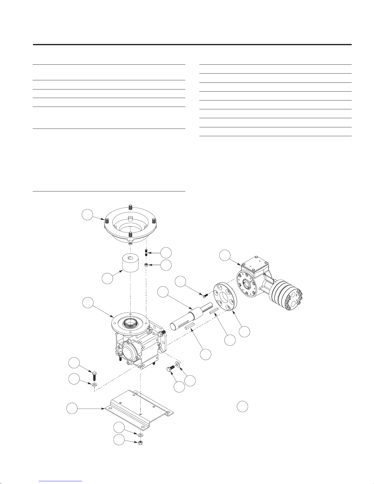
P100 Reducer Parts List
Ref. Quantity/
No. Part Number Description Pump
1 P100 Pump Assembly, NPT ............ Ref
P100 Pump Assembly, BPST .......... Ref
2 112-580 Shaft, P100/P200. ...............................1
3 D10-085-2210 Key, 0.1875 SQ x 1.00 LG, Steel .........1
4 D25-085-2210 Key, 1/4 SQ x 1.40 LG .........................1
5 112-555 Input Flange Kit, NEMA 56C Adapter .1
112-558 Input Flange Kit, IEC 63 B5 Adapter ...1
112-559 Input Flange Kit, IEC 71 B5 Adapter ...1
6 112-411 Reducer, 5:1 ratio ...............................1
112-410 Reducer, 7.5:1 ratio ............................1
112-409 Reducer, 10:1 ratio .............................1
112-408 Reducer, 15:1 ratio .............................1
112-407 Reducer, 20:1 ratio .............................1
112-405 Reducer, 30:1 ratio .............................1
112-404 Reducer, 40:1 ratio .............................1
112-403 Reducer, 50:1 ratio .............................1
112-402 Reducer, 60:1 ratio .............................1
5*
Ref. Quantity/
No. Part Number Description Pump
7 F20-120-1030 Adapter, P100 Pump ...........................1
8 100-914 Screw, 5/16-18 x .75, HHCS ...............4
9 G20-089-2020 Screw, M5 x 16 mm, FHS....................6
10 100- 659 Screw, 1/4-20 UNC-2A x 1, HHCS, sst . 4
11 112-090 Baseplate, P100 ..................................1
12 100-915 Washer, at, sst, 5/16 ..........................4
13 100-063 Locknut, 1/4-20, sst .............................4
14 100-663 Washer, at, 1/4, sst ............................8
11
10
14
6
5*
14
5*
5*
2
W0043A
8
9
12
1
7
3
4
* Note: item consists of: one selected flange kit,
5*
with spacer, four studs and four nuts.
13
13
P100-991-2400C
Page 14
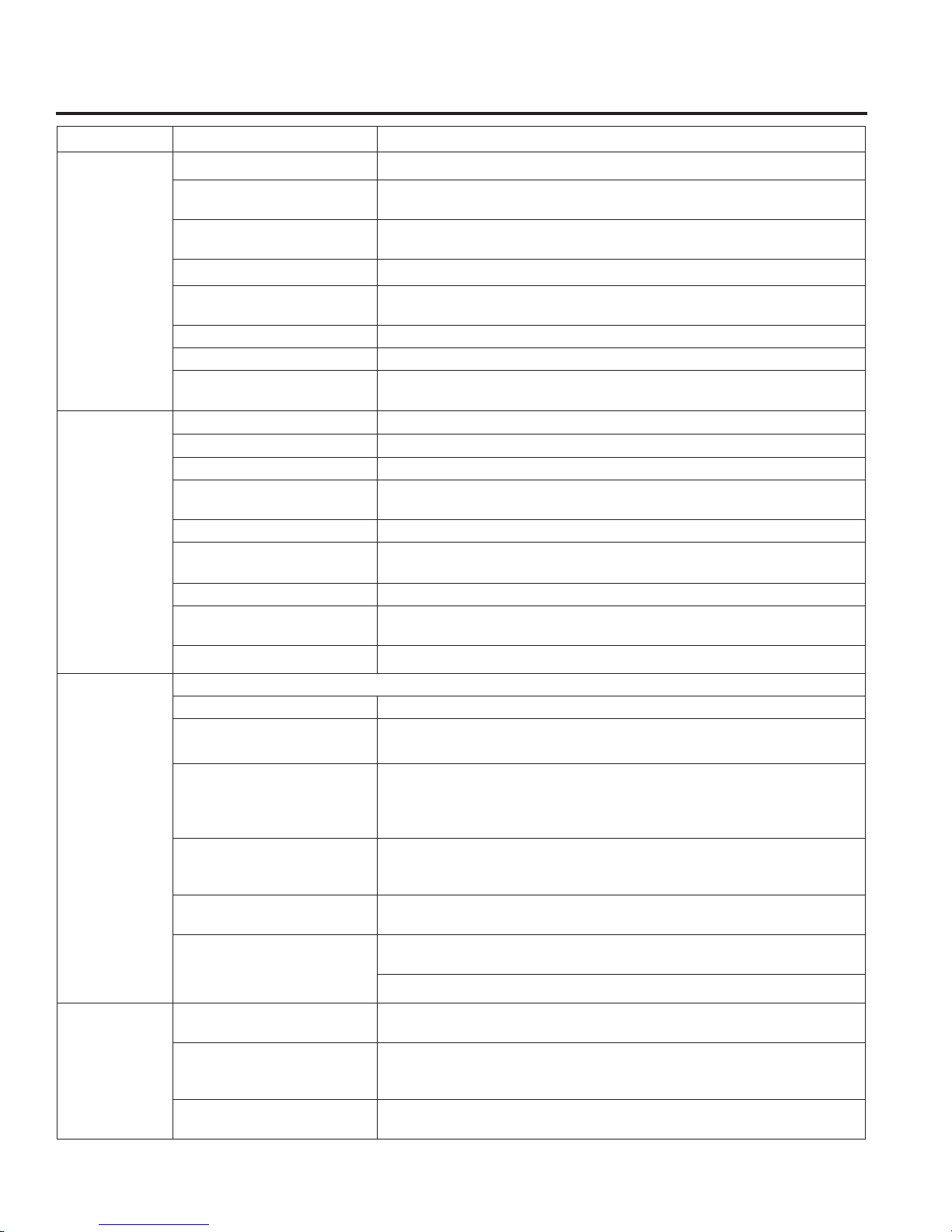
P100 Troubleshooting
Problem Probable Cause Solution
No power. Supply correct power according to motor requirements.
Motor/Pump
Does Not
Operate:
No Deliver y
Blown fuse/tripped circuit
breaker.
Shaft coupling to pump not in
place.
Current overload - motor. Motor not rated for pump operating conditions - install proper motor.
Thermal overload - motor. Motor not rated for pump and/or ambient operating conditions - supply
Faulty motor drive/controller. Repair/replace.
Faulty motor. Repair/replace.
Low liquid level in supply tank
(if low-level shut-o is used).
Supply tank empty. Fill tank.
Loss of prime Re-prime using Initial Start-Up Procedure.
Inlet line or strainer clogged. Clear debris and ush, or replace.
Inadequate supply pressure at
pump inlet.
Inlet line too restrictive. Increase inlet line diameter and/or decrease inlet line length.
Fluid viscosity too high. Reduce viscosity if possible (by heat or some other means). Increase inlet
Vapor lock/cavitation. Increase inlet pressure. Decrease uid temperature.
Pump valves held open or
worn out.
System relief valve actuating. Adjust relief valve, or repair, clean, or replace with new relief valve.
Replace/reset, eliminate circuit overload.
Install proper coupling hardware (see parts list).
cooling or install proper motor.
Fill tank.
Increase supply pressure by raising uid level in tank, raising tank, or
pressurizing suction tank.
line diameter and/or decrease inlet line length. Increase supply pressure.
Clear debris and ush, or replace (see Fluid End Service)
Delivery Too
Low and/or
Erratic
Delivery Too
High and/or
Erratic.
Review all Probable Causes and Solutions in Problem 2 No Delivery above.
Air leak(s) in inlet line. Locate all leaks and repair.
System back pressure too low. Adjust back pressure valve to higher setting. Install back pressure valve if
none in system.
Pumped uid characteristics
changed.
Inlet supply pressure changed. Monitor inlet supply pressure (at the pump) to determine if it is too low,
Pump OK - Calibration system
or ow meter error.
Oil condition in pump hydraulic
end changed.
System back pressure too low. Adjust back pressure valve to higher setting. Install back pressure valve if
Inlet supply pressure changed. Monitor inlet supply pressure (at the pump) to determine if it is too high,
Pump OK - Calibration system
or ow meter error.
Monitor supply tank temperature to determine if uid is too hot (leading to
cavitation) or too cold (increasing uid viscosity). Stabilize temperature at
suitable level to resolve problem. Check for entrapped air in the uid supply
system.
causing a starved condition/cavitation. Stabilize pressure at suitable level
to resolve problem.
Evaluate components and repair/correct problem(s).
Check oil level - if low evaluate for source of leakage. Consult factory for
hydraulic end service.
Change oil per recommended guidelines in maintenance section.
none in system.
causing a “ow-through” condition. Stabilize pressure at suitable level to
resolve problem.
Evaluate components and repair/correct problem(s).
14
P100-991-2400C
Page 15
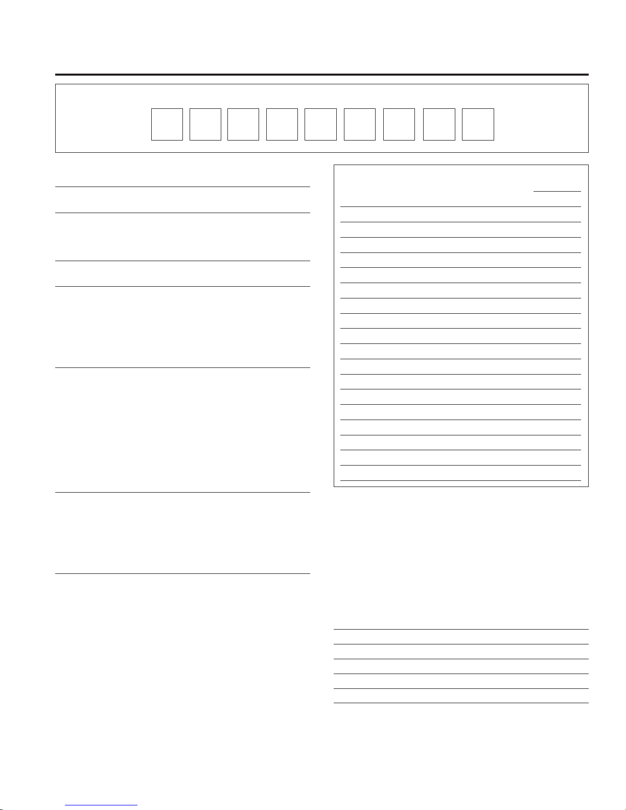
P100 Replacement Parts Kits
TO ORDER REPLACEMENT PARTS KIT: A Replacement Parts Kit contains 9 digits corresponding to customer-specied design options.
1
Order
2
Digit Code Description
1-2 Pump Conguration
P1 For all P100 Pumps
3 Kit Designator
K Complete Fluid End Kit*
D Diaphragm Kit*
V Valve Kit
4-5 Pump Head Version
52 Standard
6 Spring Retainers/Dampening Washers
B Brass
M For PVDF pump head
P For Polypropylene pump head
S For 316 Stainless Steel pump head
T For Hastelloy® C pump head
X Not included in Diaphragm Kit
7 Diaphragm & O-ring Material
A Aas/PTFE O-rings (Synthetic Oil)
E EPDM (EPDM Compatible Oil)
X FKM (Synthetic Oil)
S FKM (Food Contact Oil)
J PTFE (Food Contact Oil)
W PTFE (Synthetic Oil)
P Neoprene (Synthetic Oil)
R Neoprene (Food Contact Oil)
T Buna-N (Synthetic Oil)
F Buna-N (Food Contact Oil)
8-9 Check Valve Material
(Valve Spring / Valve & Seat)
SS Elgiloy / 316 SST
TT Hastelloy® C / Hastelloy® C
SC Elgiloy / Ceramic
TC Hastelloy® C / Ceramic
XX Not included in Diaphragm Kit
* Includes Hydraulic End Oil
6 953
Kit Contents
Kit Designator
Part Number† Description Qty K D V
D03 -018 -_ __ Diaphragm 1 • •
F20- 073-_ __ O-ring, outlet manifold 1 • • •
F2 0- 074- ___ O-ring, inlet manifold 1 • • •
D03-035-___ O-ring, outlet valve seat 1 • •
D03-020-___ Valve seat, outlet 1 • •
D03-021- __ _ Valve, outlet 1 • •
D03-022-_ __ Valve spring, outlet 1 • •
‡D03-092-___ Tetra Seal®, outlet 1 • •
D03-023-__ _ Retainer, outlet valve spring 1 • •
D03-125-_ __ Washer, outlet dampening 1 • •
D11-0 35 -__ _ O -ring, inlet valve seat 1 • •
D10-020-___ Valve seat, inlet 1 • •
D10- 021-__ _ Valve, inlet 1 • •
D10- 022-___ Valve spring, inlet 1 • •
‡D10-092-_ __ Tetra Seal®, inlet 1 • •
D10- 023-___ Retainer, inlet valve spring 1 • •
A01-113-3400 Thread locker 1 • •
Hydraulic End Oil (0.5 qt) • •
† Last four digits of part numbers with –_ _ _ refer to specic material
of construction.
‡ Not included with metal spring retainers.
7
84
P100 Tool Kit
The P100 Tool Kit (Part No. A03-175-1105) contains the tools
listed below. These tools are used to assist in the repair and
maintenance of the P100. See the maintenance sections of
this manual for specic application.
Ref. Quantity/
No. Tool Part No. Tool Description Kit
1 A03-125-1020 Holder, Plunger ...................................1
2 A03-195-1200 Rotator, Shaft ......................................1
3 A03-196-1000 Lifter, Plunger ......................................1
4 A03-124-1200 Lever Assembly ..................................1
7 A03-126-1500 Tool Box ..............................................1
15
P100-991-2400C
Page 16
P100 Warranty
Limited Warranty
Wanner Engineering, Inc. extends to the original purchaser
of equipment manufactured by it and bearing its name, a
limited one-year warranty from the date of purchase against
defects in material or workmanship, provided that the
equipment is installed and operated in accordance with the
recommendations and instructions of Wanner Engineering,
Inc. Wanner Engineering, Inc. will repair or replace, at its
option, defective parts without charge if such parts are
returned with transportation charges prepaid to Wanner
Engineering, Inc., 1204 Chestnut Avenue, Minneapolis,
Minnesota 55403.
This warranty does not cover:
1. The electric motors (if any), which are covered by
the separate warranties of the manufacturers of these
components.
2. Normal wear and/or damage caused by or related to
abrasion, corrosion, abuse, negligence, accident, faulty
installation or tampering in a manner which impairs normal
operation.
3. Transportation costs.
This limited warranty is exclusive, and is in lieu of any
other warranties (express or implied) including warranty of
merch an tabil it y or wa rra nt y of t ness for a particu lar purp ose
and of any non-contractual liabilities including product
liabilities based on negligence or strict liability. Every form
of liability for direct, special, incidental or consequential
damages or loss is expressly excluded and denied.
Wanner Engineering, Inc.
World Headquarters & Manufacturing
Wanner Engineering, Inc
1204 Chestnut Avenue,
Minneapolis, MN 55403 USA
Phone: 612-332-5681 ● Fax: 612-332-6937
Toll-Free Fax (USA): 800-332-6812
Email: [email protected]
www.Hydra-Cell.com
207 US Highway 281
Wichita Falls, TX 76310 USA
Phone: 940-322-7111
Toll-Free Fax: 800-234-1384
Email: [email protected]
www.Hydra-Cell.com
Latin American Ofce
São Paulo, Brazil
Phone: +55 (11) 4081-7098
Email: [email protected]
www.Hydra-Cell.com
Wanner International Ltd.
Wanner International Ltd
Hampshire - United Kingdom
Phone: +44 (0) 1252 816847
Email: [email protected]m
www.Hydra-Cell.eu
Wanner Pumps Ltd.
Wanner Pumps Ltd.
Kowloon - Hong Kong
Phone: +852 3428 6534
Email: [email protected]
www.WannerPumps.com
Shanghai - China
Phone: +86-21-6876 3700
Email: [email protected]
www.WannerPumps.com
© 2005 Wanner Engineering, Inc. Printed in USA
P100-991-2400C 8/2005, Revised 3/2016
 Loading...