

Hydra-Cell D-10, G-10 Installation & Service Manual
Installation & Service
W0215B
W0214B
D10-991-2400B
Models:
D-10 and G-10
WANNER ENGINEERING, INC.
1204 Chestnut Avenue, Minneapolis, MN 55403
TEL: (612) 332- 5 6 81 FA X: (612) 332- 693 7
TOLL-FREE FAX [US only]: (800) 332-6812
www.hydra-cell.com
email: sales@wannereng.com
D/G-10 Contents
Page
Specifications ..........................................................................2
Dimensions .............................................................................4
Installation ...............................................................................5
Maintenance ............................................................................9
Service (Fluid End) ...............................................................10
Service (Hydraulic End) ........................................................15
Troubleshooting ....................................................................18
D/G-10 Specifications
Max Pressure Metallic: 1000 psi (70 bar)
Non-Metallic: 250 psi (17 bar)
Slurry Duty (SD): 300 psi (21 bar)
Capacity @ Max Pressure
rpm gpm I/min
D/G-10-X 1450 7.8 29.0
D/G-10-E 1750 8.0 30.3
D/G-10-S 1750 6.0 22.7
D/G-10-I 1750 3.9 14.9
Delivery @ Max Pressure
revs/gal revs/liter
D/G-10-X 185 50
D/G-10-E 219 58
D/G-10-S 292 77
D/G-10-I 448 117
Max Inlet Pressure
Metallic: 250 psi (17 bar)
Non-Metallic: 50 psi (3.5 bar)
Slurry Duty (SD): 50 psi (3.5 bar)
Max Temperature
Metallic: 250°F (121°C) – consult factory for
temperatures above 160°F (71°C)
Non-Metallic: Polypropylene: 120°F (49°C);
Kynar, Celcon & Slurry Duty: 140°F
(60°C) – consult factory for tempera tures above 120°F (49°C)
Inlet Port D-10: 1 inch NPT
G-10: 1 inch BSPT
Discharge Port D-10: 3/4 inch NPT
G-10: 3/4 inch BSPT
Shaft Diameter 7/8 inch (22.22 mm)
Shaft Rotation Bidirectional
Bearings Tapered roller
Oil Capacity 1.1 US quarts (1.05 liters)
Weight Metallic Heads: 48 lbs (22 kg)
Non-Metallic Heads: 35 lbs (16 kg)
Calculating Required
Horsepower (kW)*
15 x rpm
63,000
15 x rpm
84,428
* rpm equals pump shaft rpm. HP/kW is required application
power. Use caution when sizing motors with variable speed
drives.
+
+
gpm x psi
1,4 60
lpm x bar
511
=
electric motor HP*
=
electric motor kW*
2
D10-991-2400B
RPM
0
NPSHr (feet of water)
NPSHr (meters of water)
1750
0 200 400 600 800 1000 1200 1400 1600 1800
4
8
12
16
20
24
0
1
2
3
4
5
6
7
1450
D/G-10-X
D/G-10-E
D/G-10-S
D/G-10-I
W0235
RPM
0 200 400 600 800 1000 1200 1400 1600 1800
10.0
0
9.0
8.0
7.0
6.0
5.0
4.0
3.0
2.0
1.0
1750
Liters Per Minute
Gallons Per Minute
16.0
18.0
20.0
22.0
24.0
26.0
14.0
30.0
32.0
34.0
36.0
38.0
28.0
2.0
4.0
6.0
8.0
10.0
12.0
0
D/G-10-I
D/G-10S
D/G-10-E
1450
D/G-10-X
200 PSI (14 bar)
500 PSI (35 bar)
1000 PSI (70 bar)
W0236
1450
1750
RPM
0
Lift (feet of water)
0
1
2
3
4
5
6
7
8
200 400 600 800 1000 1200 1400 1600 1800
D/G-10-X
D/G-10-E
D/G-10-S
D/G-10-I
Lift (meters of water)
0
1.0
0.5
1.5
2.0
2.5
W0234
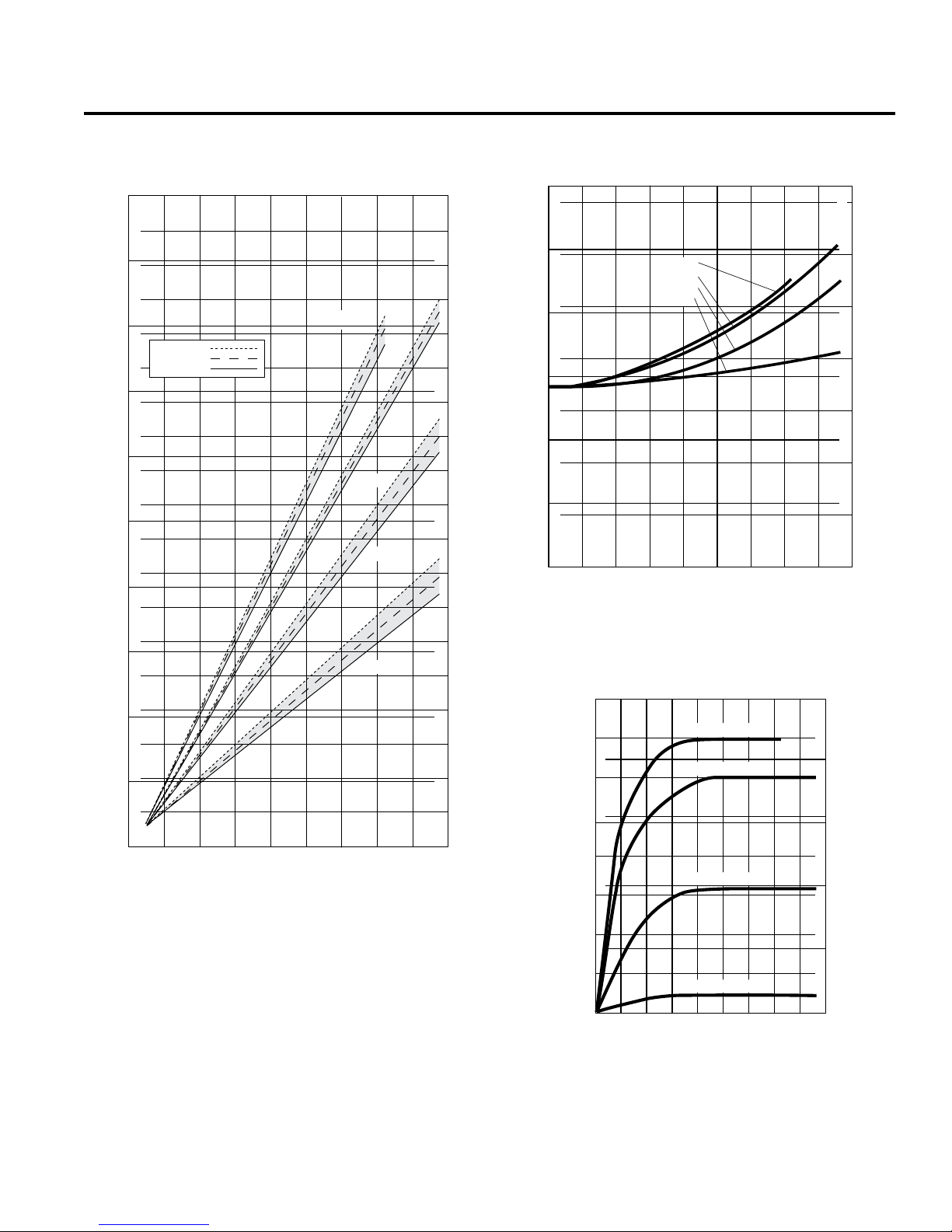
D/G-10 Specifications
Performance* Net Positive Suction Head –
NPSHr*
* Specifications depict D/G-10 metallic and non-metallic pump
head models only. Contact factory or visit our web site (www.
hydra-cell.com) for performance specifications on slurry duty
(SD) models.
Dry Lift*
3
D10-991-2400B
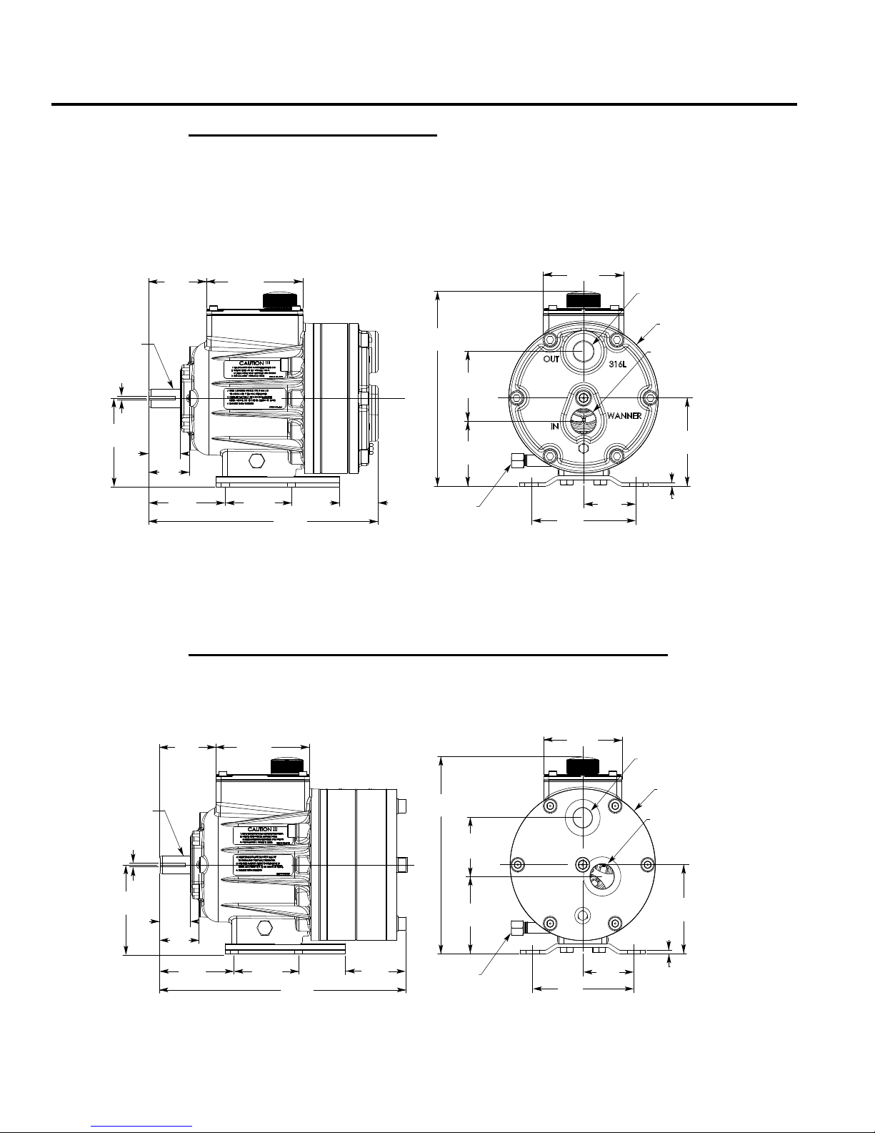
D/G-10 Dimensions
W0527
4.27
(108.3)
Outlet
D-10: 3/4" NPT
G-10: 3/4" BSPT
4.97
(126.2)
2.48
(63.1)
2.82
(71.5)
1.52
(38.6)
1.97
(50.0)
4.67
(118.7)
3.78
(96.0)
3.00
(76.2)
11.14
(283.0)
1.86
(47.3)
Oil Drain
(either side)
3.14
(79.8)
3.38
(85.7)
9.42
(239.2)
3.91
(99.2)
Ø7.27
(184.6)
Inlet
D-10: 1" NPT
G-10: 1" BSPT
4.27
(108.3)
.187
(4.75)
0.187
(4.74)
Ø0.875
(22.23)
1.52
(38.6)
1.97
(50.0)
2.82
(71.5)
4.67
(118.7)
4.27
(108.3)
3.78
(96.0)
3.00
(76.2)
12.31
(312.7)
3.03
(77.1)
0.187
(4.74)
Ø0.875
(22.23)
W0528
4.97
(126.2)
2.48
(63.1)
3.91
(99.2)
Outlet
D-10: 3/4" NPT
G-10: 3/4" BSPT
Oil Drain
(either side)
3.70
(94.0)
2.81
(71.4)
9.42
(239.2)
Ø7.25
(184.2)
Inlet
D-10: 1" NPT
G-10: 1" BSPT
4.27
(108.3)
.19
(4.7)
Models with Metallic Pumping Head
Brass
Cast Iron
316 Stainless Steel
Nickel Alloy (C Series)
Models with Non-Metallic or Slurry Duty (SD) Pump Head
®
Kynar
Polypropylene
Celcon
4
D10-991-2400B
D/G-10 Installation
W0219
Location
Locate the pump as close to the supply source as possible.
Install it in a lighted clean space where it will be easy to inspect
and maintain. Allow room for checking the oil level, changing
the oil, and removing the pump head (manifold, valve plate and
related items).
Mounting
The pump shaft can rotate in either direction.
To prevent vibration, mount the pump and motor securely on
a level rigid base.
On a belt-drive system, align the sheaves accurately; poor
alignment wastes horsepower and shortens the belt and bearing
life. Make sure the belts are properly tightened, as specified by
the belt manufacturer.
On a direct-drive system, align the shafts accurately. Unless
otherwise specified by the coupling manufacturer, maximum
parallel misalignment should not exceed 0.015 in. (0.4 mm)
and angular misalignment should be held to 1° maximum.
Careful alignment extends life of the coupling, pump, shafts,
and support bearings. Consult coupling manufacturer for exact
alignment tolerances.
Important Precautions
Adequate Fluid Supply. To avoid cavi tatio n and
premature pump failure, be sure that the pump will have
an adequate fluid supply and that the inlet line will not be
obstructed. See “Inlet Piping”.
Positive Displacement. This is a positive-displacement
pump. To avoid severe system damage if the discharge line
ever becomes blocked, install a relief valve downstream
from the pump. See “Discharge Piping”.
Safety Guards. Install adequate safet y guards over
all pulleys, belts, and couplings. Follow all codes and
regulations regarding installation and operation of the
pumping system.
Shut-Off Valves. Never install shut-off valves between
the pump and discharge pressure regulator, or in the
regulator bypass line.
Freezing Conditions. Protect the pump from freezing.
See also the Maintenance Section.
Consult the Factory for the following situations:
• Extreme temperature applications – above 160° F. (71°
C) or below 40° F. (4.4° C)
• Pressure feeding of pumps
• Viscous or abrasive fluid applications
• Chemical compatibility problems
• Hot ambient temperatures – above 110° F. (43° C)
• Conditions where pump oil may exceed 200° F. (93° C)
because of a combination of hot ambient temperatures,
hot fluid temperature, and full horsepower load — an
oil cooler may be required
5
D10-991-2400B

D/G-10 Installation
Inlet Piping (Suction Feed)
CAUTION: When pumping at temperatures above 160° F
(71° C), use a pressure-feed system.
Install draincocks at any low points of the suction line, to permit
draining in freezing conditions.
Provide for permanent or temporary installation of a vacuum
gauge to monitor the inlet suction. To maintain maximum flow,
vacuum at the pump inlet should not exceed 7 in. Hg at 70° F
(180 mm Hg at 21° C). Do not supply more than one pump
from the same inlet line.
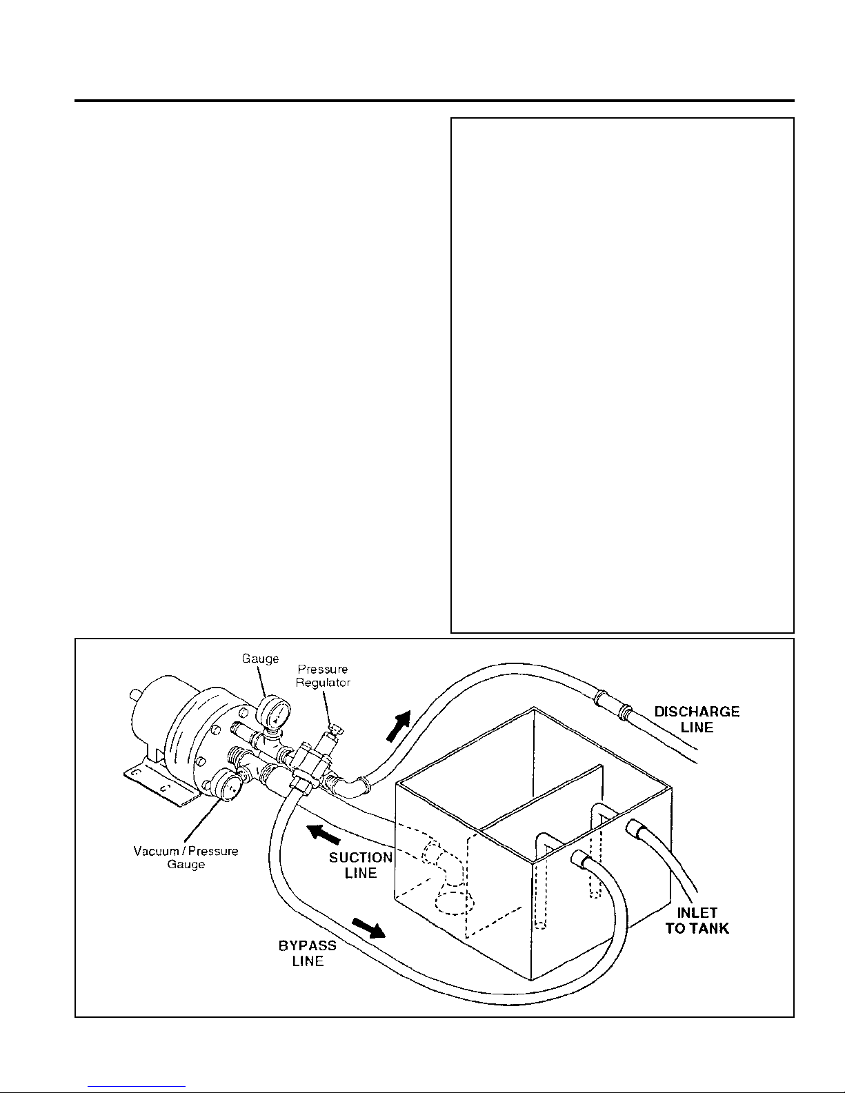
Supply Tank
Use a supply tank that is large enough to provide time for any
trapped air in the fluid to escape. The tank size should be at
least twice the maximum pump flow rate.
Isolate the pump and motor stand from the supply tank, and
support them separately.
Install a separate inlet line from the supply tank to each pump.
Install the inlet and bypass lines so they empty into the supply
tank below the lowest water level, on the opposite side of the
baffle from the pump suction line.
If a line strainer is used in the system install it in the inlet line
to the supply tank.
To reduce aerat ion and turbulence, install a completely
submerged baffle plate to separate the incoming and outgoing
liquids.
Install a vortex breaker in the supply tank, over the outlet port
to the pump.
Place a cover over the supply tank, to prevent foreign objects
from falling into it.
Hose and Routing
Size the suction line at least one size larger than the pump
inlet, and so that the velocity will not exceed 1-3 ft/sec (0.3 to
0.9 m/s):
For pipe in inches: Velocity (ft/sec) = 0.408 x GPM/Pipe ID2
For pipe in mm: Velocity (m/sec) = 21.2 x LPM/Pipe ID2
Keep the suction line as short and direct as possible. A
maximum of 3 feet (1 m) is recommended.
Use flexible hose and/or expansion joints to absorb vibration,
expansion, or contraction.
If possible, keep the suction line level. Do not have any high
points to collect vapor unless these high points are vented.
To reduce turbulence and resistance, do not use 90° elbows.
If turns are necessary in the suction line, use 45° elbows or
arrange sweeping curves in the flexible inlet hose.
If a block valve is used, be sure it is fully opened so that the flow
to the pump is not restricted. The opening should be at least
the same diameter as the inlet plumbing ID.
Do not use a line strainer or filter in the suction line unless
regular maintenance is assured. If used, it should have a freeflow area of at least three times the free-flow area of the inlet.
Install piping supports where necessary to relieve strain on the
inlet line and to minimize vibration.
Loctite is a registered trademark of Loctite Corporation.
Scotchbrite is a registered trademark of 3M Company.
Inlet Piping (Pressure Feed)
Provide for permanent or temporary installation of a vacuum/
pressure gauge to monitor the inlet vacuum or pressure.
Pressure at the pump inlet should not exceed 250 psi (17 bar);
if it could get higher, install an inlet pressure reducing regulator.
Do not supply more than one pump from the same inlet line.
Inlet Calculations
Acceleration Head
Calculating the Acceleration Head
Use the fol low ing f orm ula to c al cul ate acce lera tion head los ses.
Subtract this figure from the NPSHa, and compare the result to
the NPSHr of the Hydra-Cell pump.
Ha = (L x V x N x C) ÷ (K x G)
where:
Ha = Acceleration head (ft of liquid)
L = Actual length of suction line (ft) — not equivalent length
V = Velocity of liquid in suction line (ft/sec) [V = GPM x (0.408
÷ pipe ID
N = RPM of crank shaft
C = Constant determined by type of pump — use 0.066 for
the D-10 and G-10 Hydra-Cell pumps
K = Constant to compensate for compressibility of the fluid —
use: 1.4 for de-aerated or hot water; 1.5 for most liquids;
2.5 for hydrocarbons with high compressibility
G = Gravitational constant (32.2 ft/sec
Friction Losses
Calculating Friction Losses in Suction Piping
When following the above recommendations (under “Inlet
Piping”) for minimum hose/pipe I.D. and maximum length,
frictional losses in the suction piping are negligible (i.e., Hf =
0) if you are pumping a water-like fluid.
When pumping more-viscous fluids such as lubricating oils,
sealants, adhesives, syrups, varnishes, etc., frictional losses
in the suction piping may become significant. As Hf increases,
the available NPSH (NPSHa) will decrease, and cavitation will
oc cur.
In general, frictional losses increase with increasing viscosity,
increasing suction-line length, increasing pump flow rate, and
decreasing suction-line diameter. Changes in suction-line
diameter have the greatest impact on frictional losses: a 25%
increase in suction-line diameter cuts losses by more than
two times, and a 50% increase cuts losses by a factor of five
times.
Consult the factory before pumping viscous fluids.
Minimizing Acceleration Head and Frictional Losses
To minimize the acceleration head and frictional losses:
• Keep inlet lines less than 3 ft (1 m) long
• Use at least 1-1/2 in. (38 mm) I.D. inlet hose
• Use soft hose (low-pressure hose, non collapsing) for the
inlet lines
• Minimize fittings (elbows, valves, tees, etc.)
• Use a suction stabilizer on the inlet.
6
2
)]
2
)
D10-991-2400B
 Loading...